
HOLIDAY DONATION DRIVE - SUPPORT MSW - DO YOUR PART TO KEEP THIS GREAT FORUM GOING! (Only 13 donations so far - C'mon guys!)
×
DocRob
-
Posts
1,257 -
Joined
-
Last visited
Content Type
Profiles
Forums
Gallery
Events
Everything posted by DocRob
-
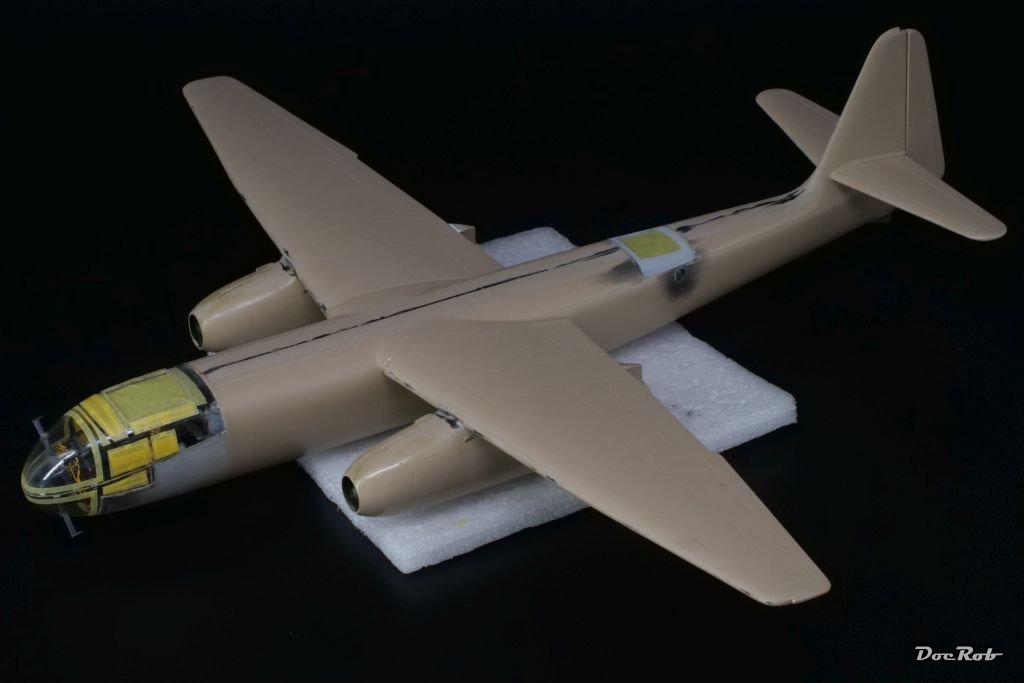
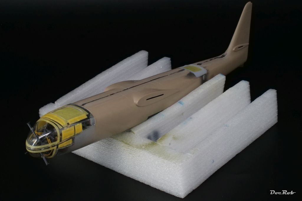
 Time and motivation are a bit sparse in the moment, but I managed to apply some color onto the Arado. After re-spraying the gloss black of the canopy after sanding, the whole canopy section was masked. The underside of the plane received a coat of RLM 76, followed by a very long masking session, a job, I really don't like. This was followed by a coat of RLM 82 Dunkelgrün (dark green) I decided against pre shading, because of the double coating in the RLM 81 Braunviolett areas. All camo colors are from AK's Real Color range and spray very fine and smooth with the added Mr. Leveling thinner. After drying, I will apply the camo masks, which are pre-cut luckily. Cheers Rob
- 79 replies
-
- 10
-

-
Nice colorful snapshot Greg, the planes in their dramatic setting look great. What a nice ensemble of racers. Cheers Rob
-
Curtiss BF 2C-1 by CDW - FINISHED - Hasegawa - 1:32 scale
DocRob replied to CDW's topic in Non-ship/categorised builds
The Curtiss has become a beauty with the colorful wings and markings. an absolute eyecatcher and you are close to the finish line. Cheers Rob -
Honda RC166 Grand Prix Racer by CDW - FINISHED - Tamiya - 1/12
DocRob replied to CDW's topic in Non-ship/categorised builds
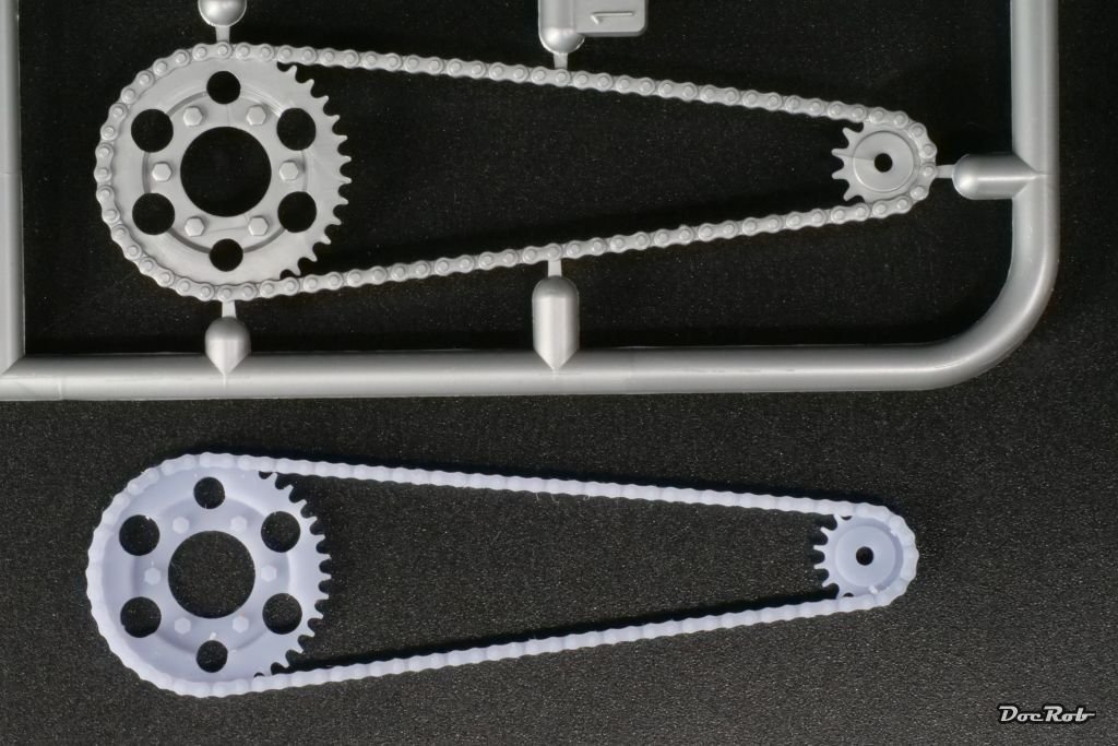
Yesterday, I received the Falcon Scale Models rendition of the chainset for Tamiya's RC166. It was well packed and is well printed too. The sideview shows a bit refined detail and slightly smaller links and gear teeth. Where the 3D printed part shines, is when you look at it from above, with the opened track links. When I build mine, I will try try the PE set, because I'm curios and I have it and then will decide. I just thought, how small these metal parts are, considering the size of the plastic chainsets. Cheers Rob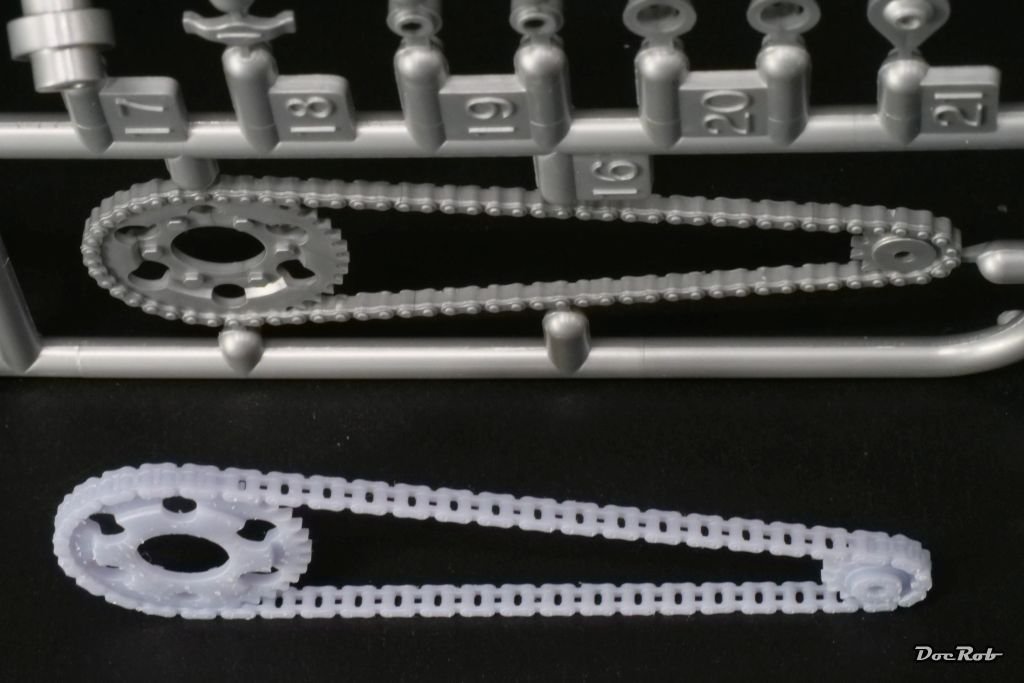
-
Congratulations, what a fantastic result. I really like the unusual planking and the myriad of deck details and rigging. Cheers Rob
-
Thank you Craig, I think with the sleek and huge Arado, it's a good idea to enhance some detail areas, to let the eye wander. I guess, that's what you mean by 'pop'. I like to replicate materials out of the plastic, that don't look plastic anymore. It's one of the keys which drives me in modelling. Cheers Rob
-
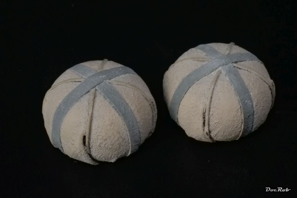
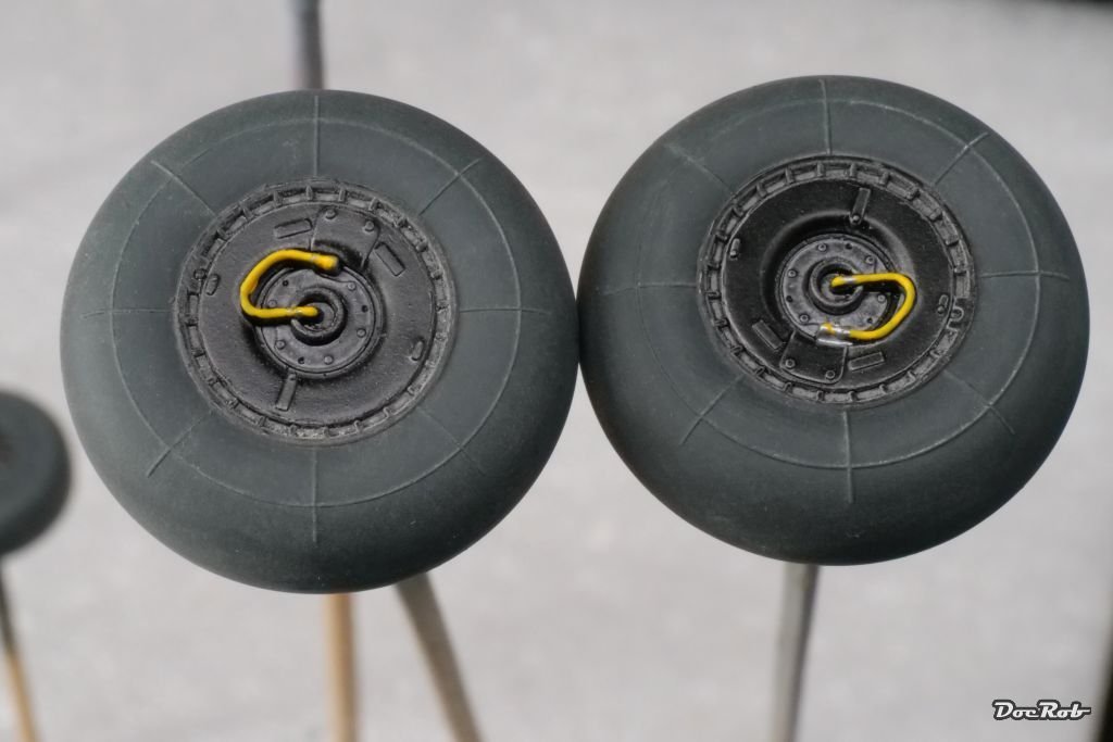
Still no masks at hand, spring can be awful here. It's the worst weather of the year, normally and every second day is a holiday, so no working customs, no working mail. Meanwhile, I painted the wheels with my usual workflow, spraying the hubs first, in this case semi matte black, then mask the hubs and spray the tires. Here I used Nato Black as a base and then sprayed the flanks with some drops of Field Blue in the Nato black. Last step are pigments in a concrete tone rubbed in for enhancing contrasts and simulating abrasion and dirt. Some details were picked out by brush on the hubs. The kit wheels look especially good, it's strange, how different the quality of the plastic parts is in this kit. Next were the parachute packs for the Ratos jets. I sprayed everything in RLM 22, masked the belts off and used Buff for the remainder. The ropes were painted by brush and then I rubbed in some concrete pigments. Cheers Rob
- 79 replies
-
- 14
-
-
Like I already said over on LSM, your Schnellboot looks perfect Kevin, great work. Cheers Rob
- 34 replies
-
- 3
-
-

-
- Schnellboot
- Revell
- (and 2 more)
-
A very interesting build thread, thanks for pointing out the shortcomings of the kit. I plan to purchase and build the Amati Fifie and your log is extremely helpful. Keep on the nice work. Cheers Rob
-
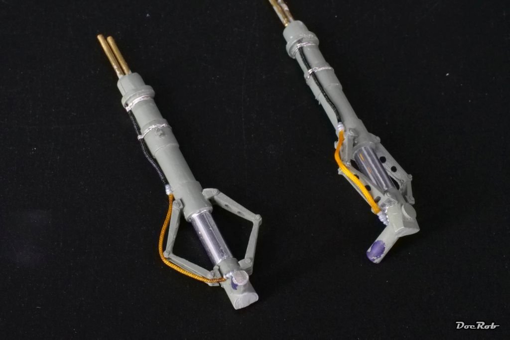
While I'm still waiting for the 1ManArmy masks to arrive, I decided to do a little detail work and gave some love to the wheel struts. The oleos where covered with AK's chrome adhesive tape, but as this is a bit stiff, Bare Metal foil would have been the better choice. My Arado 234 Monographs show the braking lines partly yellow and black, so I used my braided 0,5 mm Anyz line for the purpose along with Anyz resin connectors. The yellow line was soaked in Pledge, because otherwise it would have been to bright and have spots, where the CA stuck. The clamping strips were made from pre cut Bare Metal foil of 0,5 mm width, secured with some drops of Pledge. After drying, I will rub in some steel pigments and add some shadows and highlighting. Cheers Rob
- 79 replies
-
- 13
-
-

-
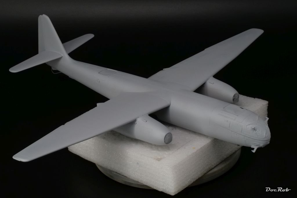
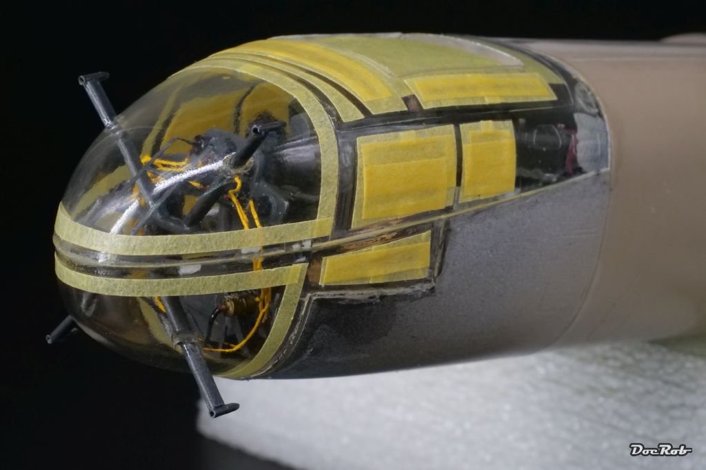
I masked wheel wells, engines and the canopy with sponges, tape and liquid mask and gave the Arado a rub with an alcohol soaked cloth. I paid a lot of attention to seal the canopy section air tight with liquid mask and with filling the gaps before with Revell Clear, because I hope to hinder the inside of the canopy from fogging due to thinner fumes. Prime (er) time - I applied Mr. Surfacer 1200, which sprayed very well as always. After drying, I sprayed the canopy section gloss black, to accept the riveted decal strips for the framing, if I decide to use them. Now I have to check, where I have to further work on the surfaces, be it filling or scribing. Meanwhile I sprayed other parts like the Rato rockets and their parachutes, external fuel tanks and the parts for the landing gear, which will be detailed with chrome oleos and braking lines next. Cheers Rob
- 79 replies
-
- 11
-
-
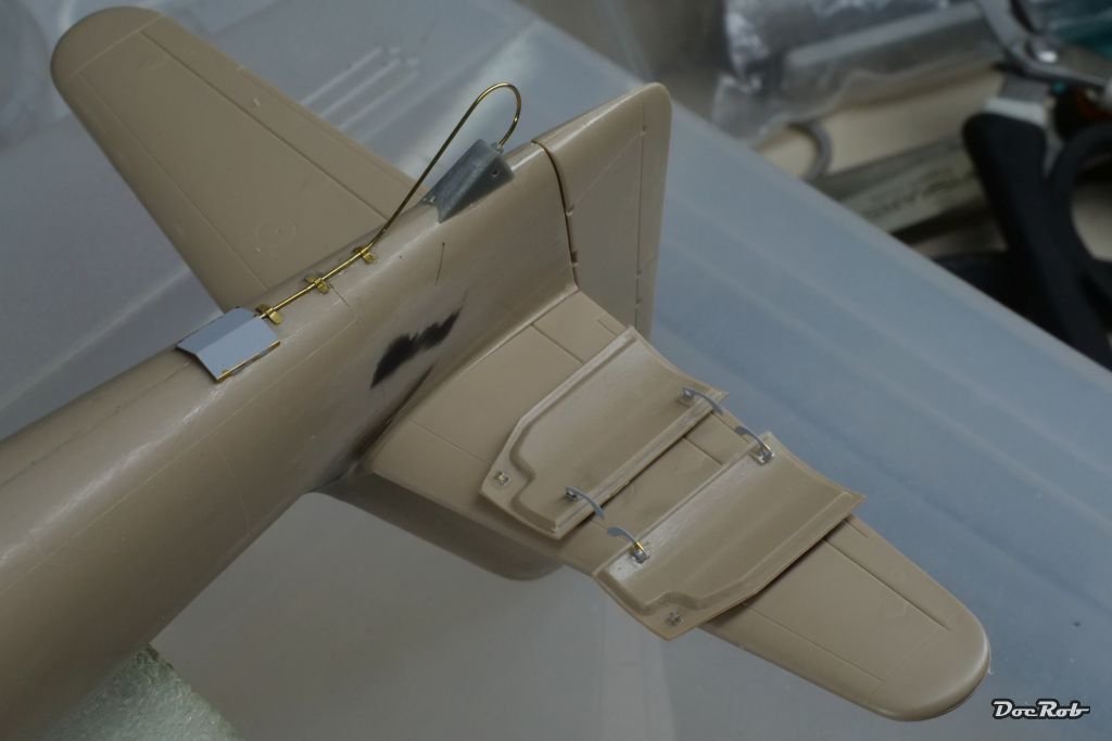
Thank you Ken. Meanwhile, there is some detail work to be done. I added the PE hinges to the wheel doors and the breaking parachute release mechanism to the fuselage, where I used 0,55 mm brass rod instead of the supplied thread. Cheers Rob
- 79 replies
-
- 12
-
-
Catching up very late, but this is absolutely beautiful, well built and refined with lots of detail, chapeau. Cheers Rob
-
I saw this lovely kit for the first time today and yes, I want to build it. Right down my alley. a small precious boat in larger scale. Cheers Rob
- 216 replies
-
- 3
-
-
- masterkorabel
- ships
- (and 3 more)
-
Curtiss BF 2C-1 by CDW - FINISHED - Hasegawa - 1:32 scale
DocRob replied to CDW's topic in Non-ship/categorised builds
Hannants in the UK has them available: Yellow Wings Aircraft decals - YW32008 | Hannants Cheers Rob -
Honda RC166 Grand Prix Racer by CDW - FINISHED - Tamiya - 1/12
DocRob replied to CDW's topic in Non-ship/categorised builds
It will take some days to get here, but I will post pictures. They have more chain sets in their catalogue. You have to open the .PDF on their site. Falcon Scale Models - Catalog / Katalog Cheers Rob -
Honda RC166 Grand Prix Racer by CDW - FINISHED - Tamiya - 1/12
DocRob replied to CDW's topic in Non-ship/categorised builds
I ordered the resin chain and if you are still interested, I will post some pictures, when it arrives. Could come handy for your second Honda - hint . Cheers Rob -
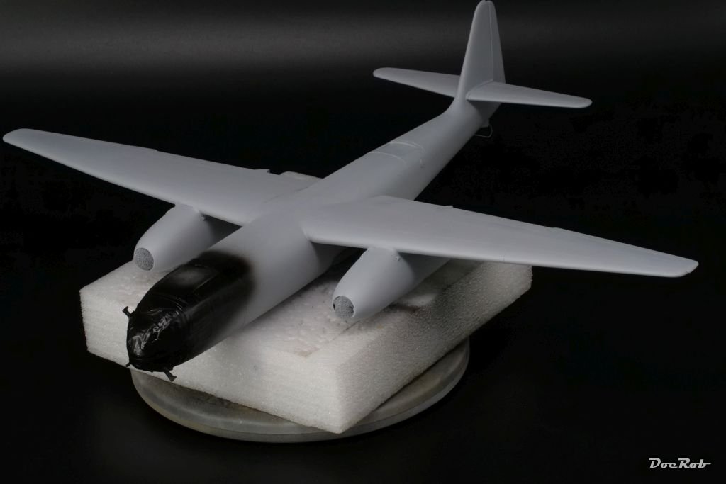
The thing got wings finally and it's tail. Fit is good so far, but a little filling will be needed at the wingroots. The Arado is a big kite and one of the main goals until the finish is not to knock off the protruding FUG antenna posts. She will not be a tail sitter, my glued in weight was sufficient. Cheers Rob
- 79 replies
-
- 13
-
-
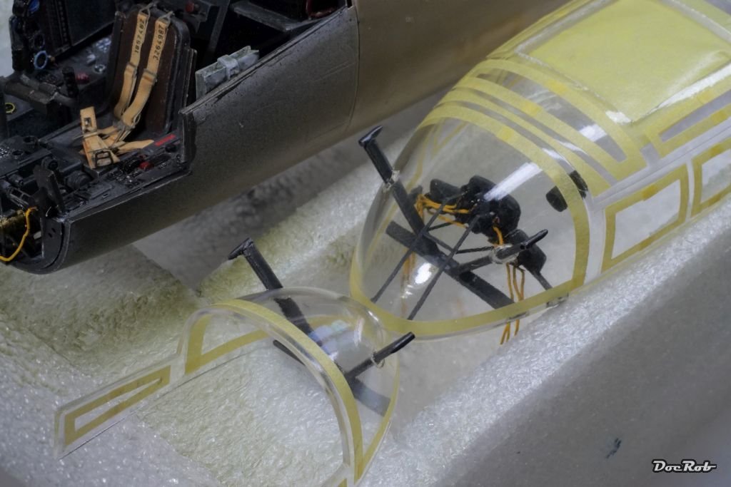
Thank you Craig, it's not the nicest of joins, but I guess painted and maybe decaled it will look ok. Decaled means, Fly provided strips of decal with bolt detail to apply over the canopy framing. I'm not finally decided, if I use these. I will look for the videos you recommended. Sometimes I watch modeling related footage during building sessions. I never spent so much time around clear parts with cutting, sanding, drilling, filling masking, gluing in parts of different materials, ... The cockpit is indeed the focal point of the Arado. Cheers Rob
-
I took all my guts and glued the canopy shut, first the lower half, followed bey the upper glasshouse. I used Tamiya cement and after the glue had settled, ran Revell Contacta Clear over the seams three times for filling and sealing. The radio operator compartment was closed as well and received the same treatment. Cheers Rob
- 79 replies
-
- 16
-
-
The masking was done a long time ago and I have to say, it was maybe the easiest part of this build . Cheers Rob
-
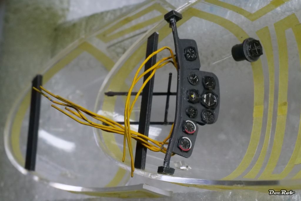
Slowly progressing with the cockpit. After finally gluing in the instrument panels struts, I added the struts for the FUG antennas and hope they are more or less correct aligned. Not an easy job, because the cockpit is slightly tilted to the front and you have only the curved canopy shapes for orientation. I finally made some touchups and let some Pledge run around the drilled holes in the clear cockpit parts. Next will be final masking and then the canopy will be glued in place, first the upper half, then stowing the cables and then the lower half. Cheers Rob
- 79 replies
-
- 15
-
-
-
Honda RC166 Grand Prix Racer by CDW - FINISHED - Tamiya - 1/12
DocRob replied to CDW's topic in Non-ship/categorised builds
Wow, what a beauty Craig with only one thing missing. You have to build a second one to present them side by side with and without fairing. I can't say, which I like better. It's a pity to hinder the eye wandering over the precious engine and other details, but the slender look of the faired bike with your beautiful paintjob is a stand out as well. Decisions, decisions, at least for my build to come. Cheers Rob -
I managed to get some of the hard stuff done. I'm never to keen about gluing parts into canopies, but here it's a bit more than the odd rearview mirror and it's a mix of materials, plastic, resin and PE. The canopy was bathed in Pledge before masking, a long time ago and my recent glue tests showed, that there is no fogging with my CA and Tamiya cement. I somehow fiddled in the IP and the IP framing, after I installed the base strips for the antler struts. It was not easy to align the parts without smearing glue somewhere on the inside of the canopy, but I think, I got it done. The IP got two shim parts made from styrene, where they meet the canopy for a larger gluing surface. Now I let that dry until tomorrow and then will attach the lower struts of the IP framing and make some touch ups. Cheers Rob
- 79 replies
-
- 14
-
-
Th Arado was also a great reconnaissance airplane, being able to fly very high and having less engine vibrations, than prop driven planes. It was a very steady camera base and delivered pictures of unmatched sharpness. Cheers Rob