HOLIDAY DONATION DRIVE - SUPPORT MSW - DO YOUR PART TO KEEP THIS GREAT FORUM GOING! (Only 36 donations so far out of 49,000 members - C'mon guys!)
×


Srenner
-
Posts
220 -
Joined
-
Last visited
Content Type
Profiles
Forums
Gallery
Events
Everything posted by Srenner
-
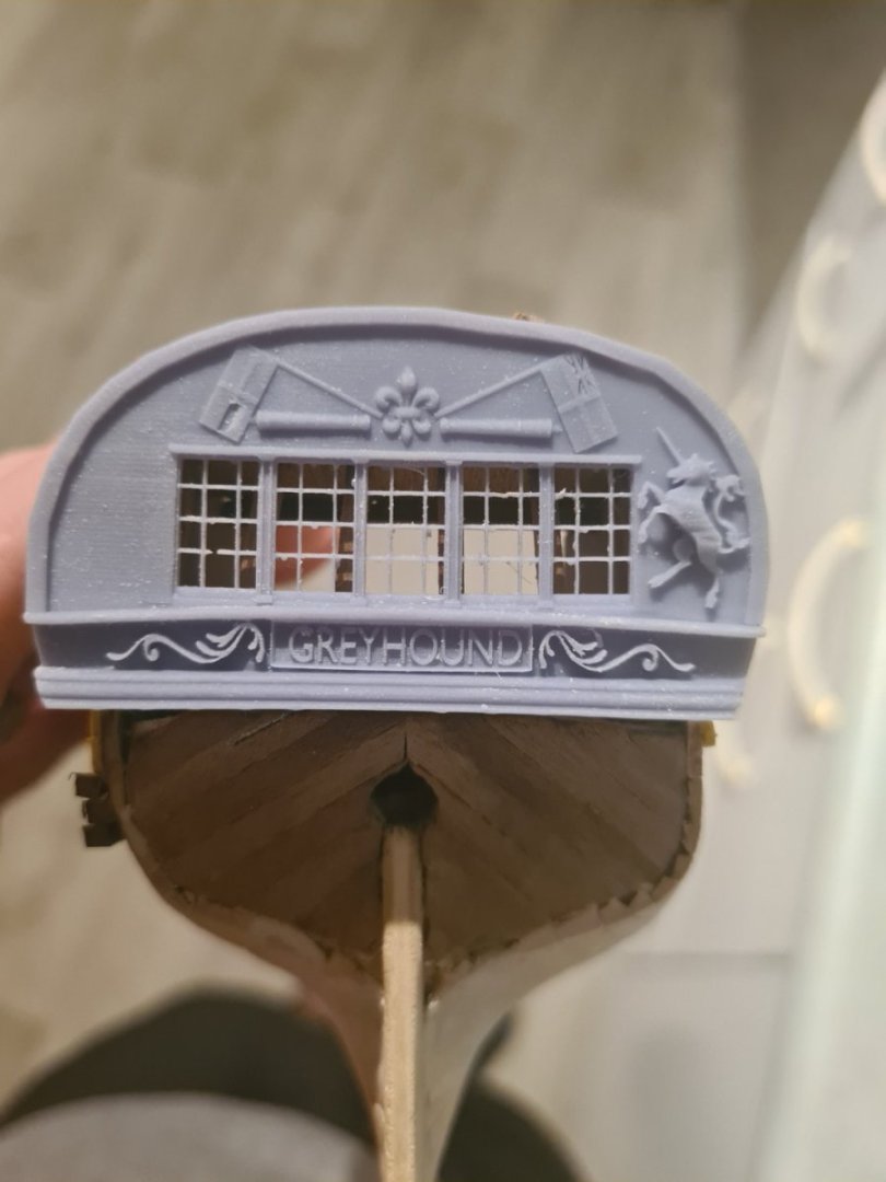
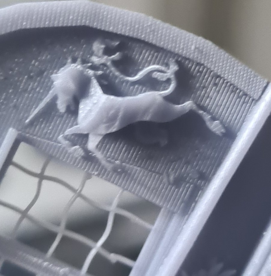
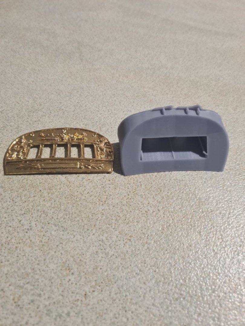
The stern carvings are coming together now and I made a nice print by only tilting about 20 degrees instead of the 45 I was before. Also beefing up the contacts with the supports helps it not to pull away while it's being printed. I'm working on the lion but as you can see the results are a lot better than the piece supplied with the kit. And because of the scandalous use of hms nelson carving on the coral piece I felt I could do what I wanted with it to a degree

-
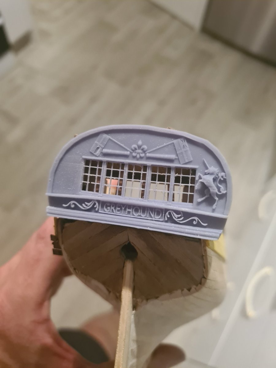
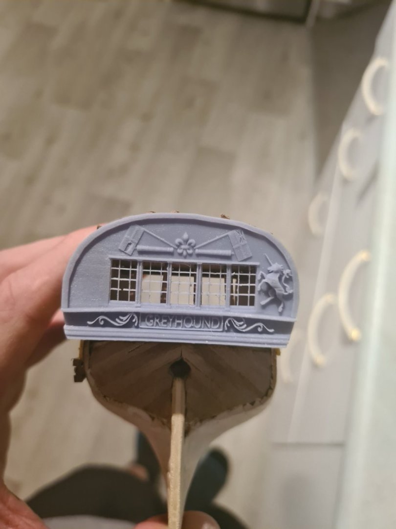
After mesh wrangling all weekend I have tried a test print on the unicorn... surprised it doesn't look too bad. Going to increase its thickness a little bit more so it stands out as a relief off the surface.
-
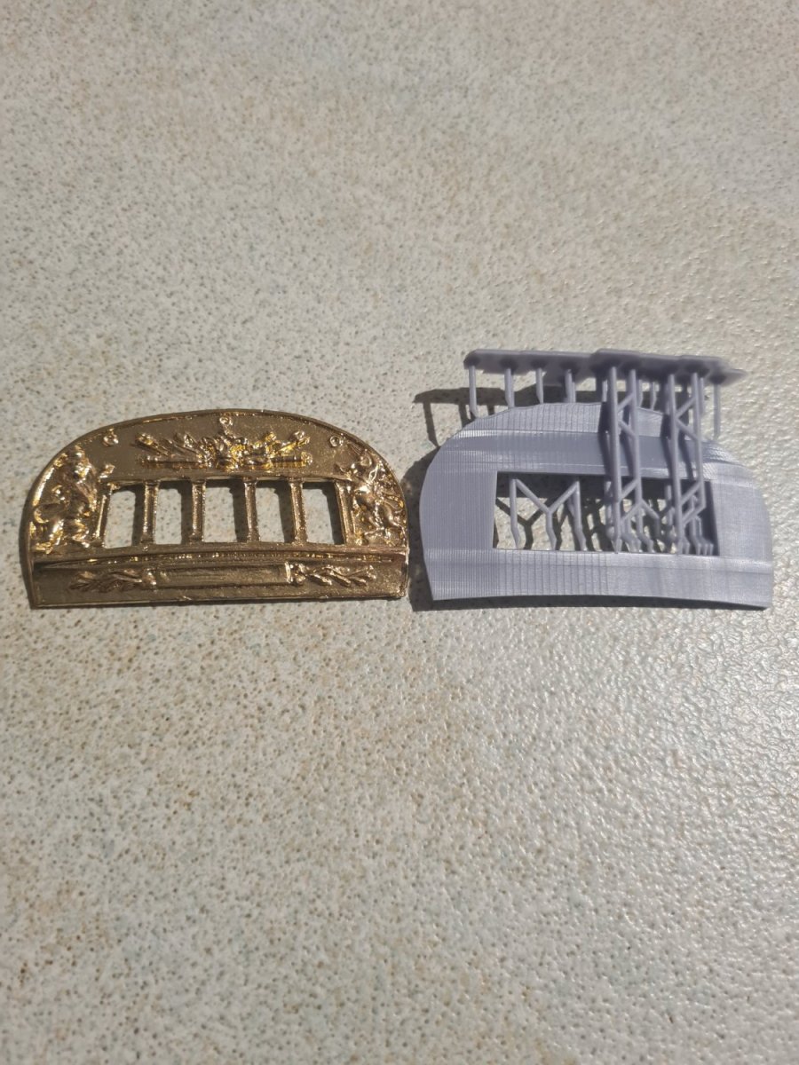
Build update... its taken a lot of time and mucking around in blender but ove reached the beginner stage I think... starting to get closer results to the piece supplied in the kit. I noticed one of the sections on the stern has be ripped from hms Victory... so don't feel as bad taking a little bit of poetic license with the decorations. I'm going to make a running greyhound as the figurehead.

.png.5f5fa43033c7109321453ad7bc84f763.png)
-
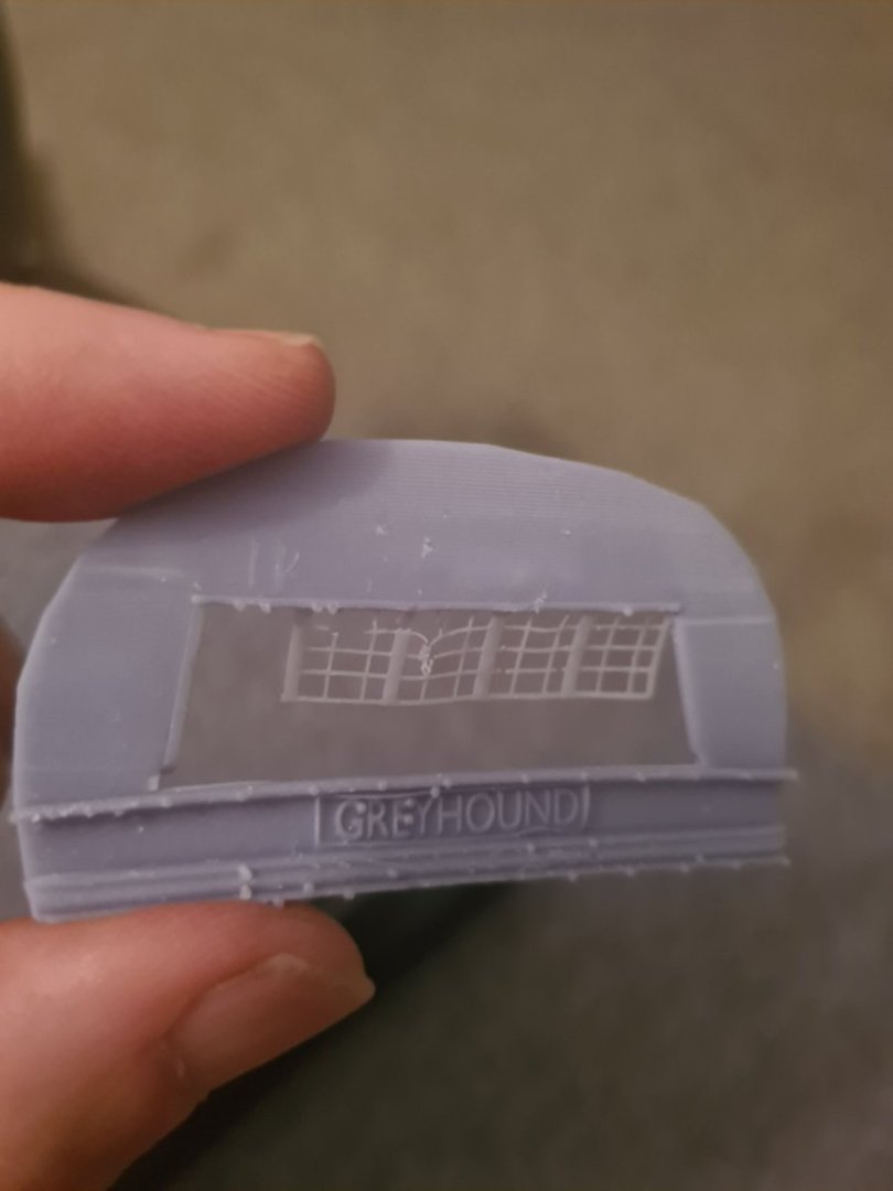
Failed print but also not fine enough detail
Srenner replied to Srenner's topic in 3D-Printing and Laser-Cutting.
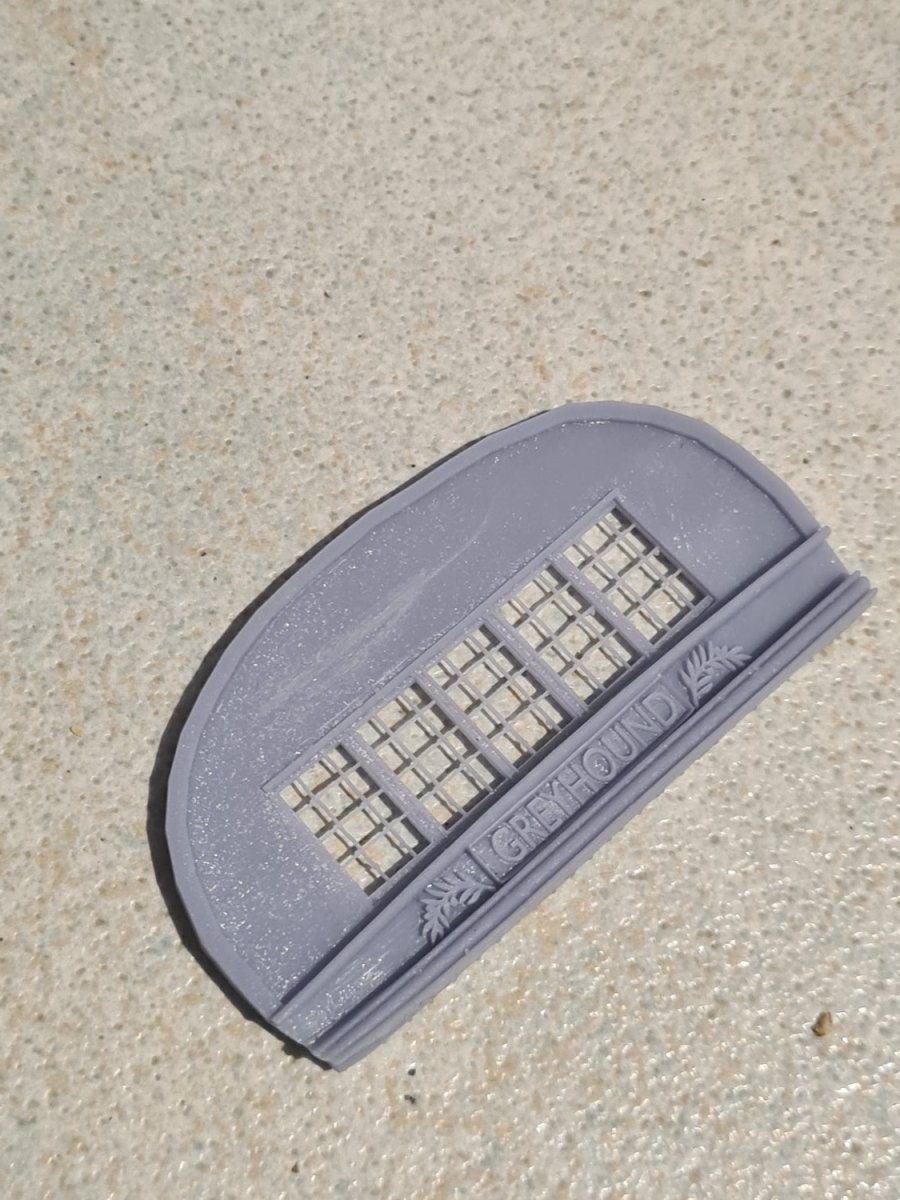
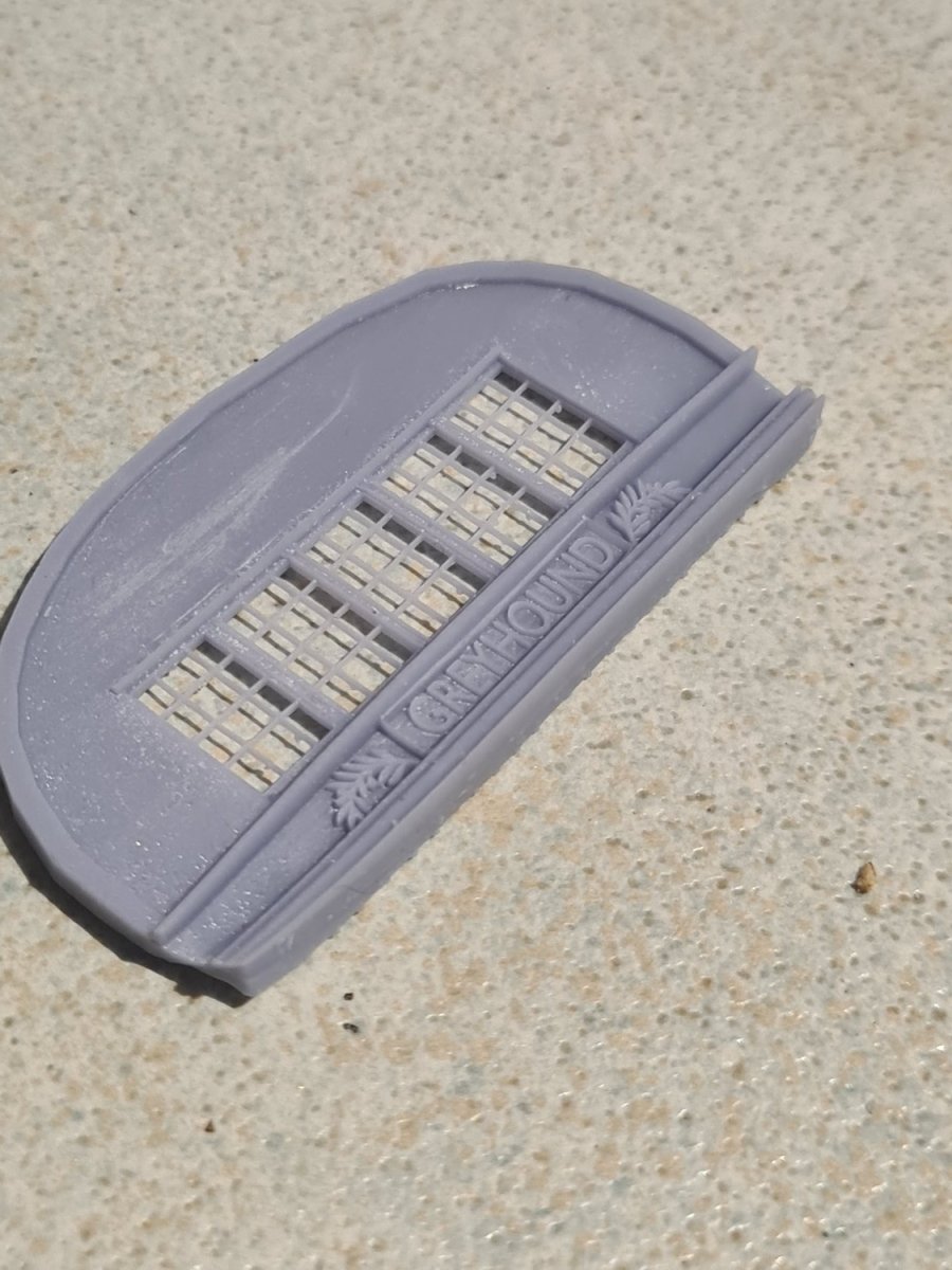
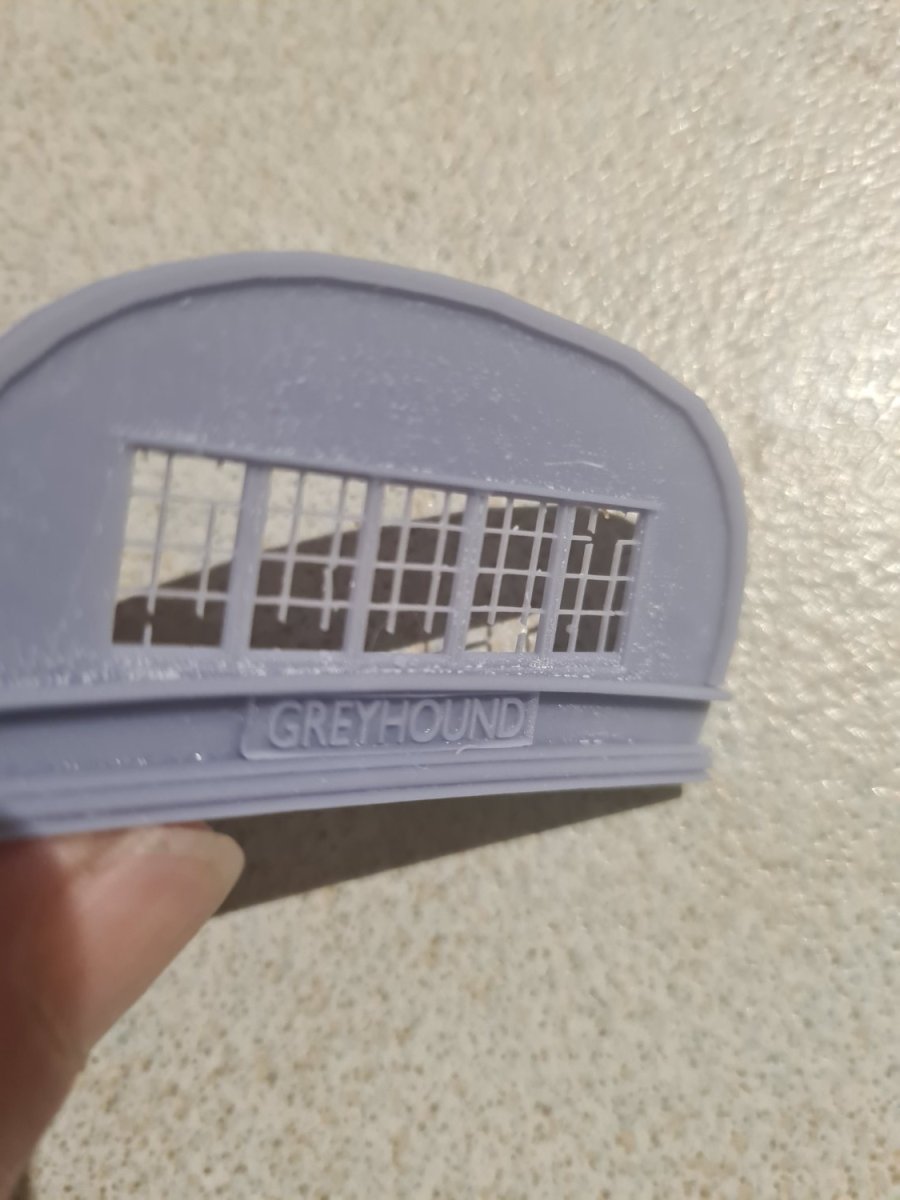
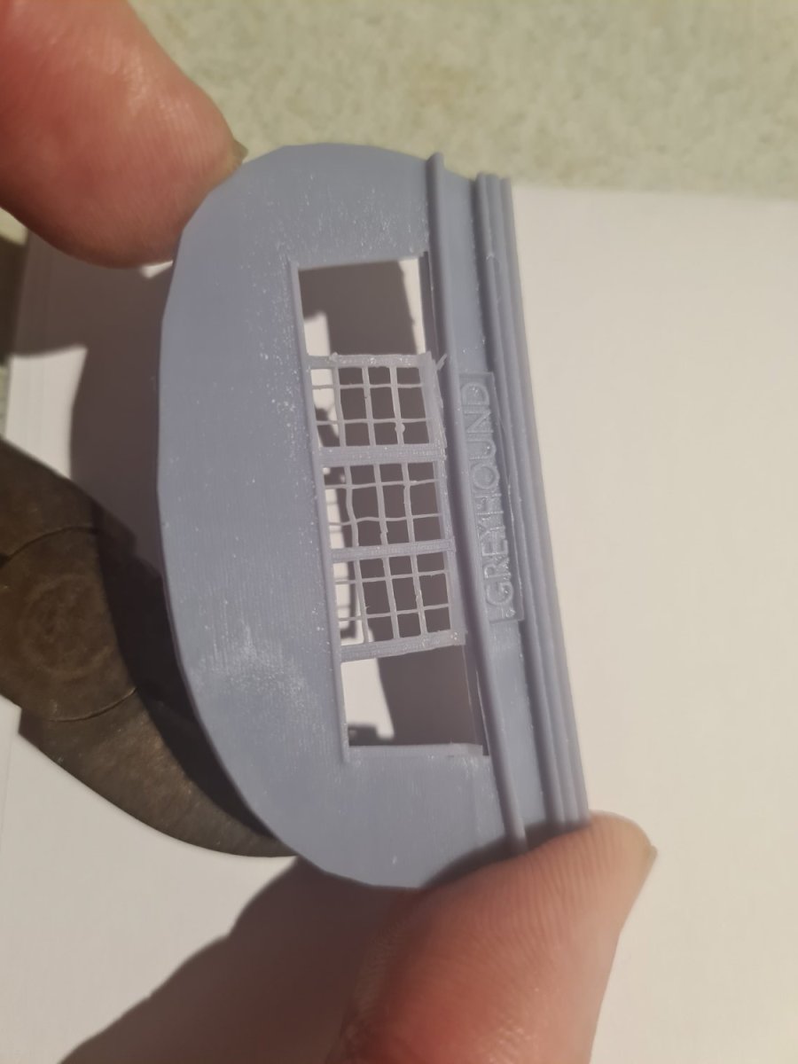
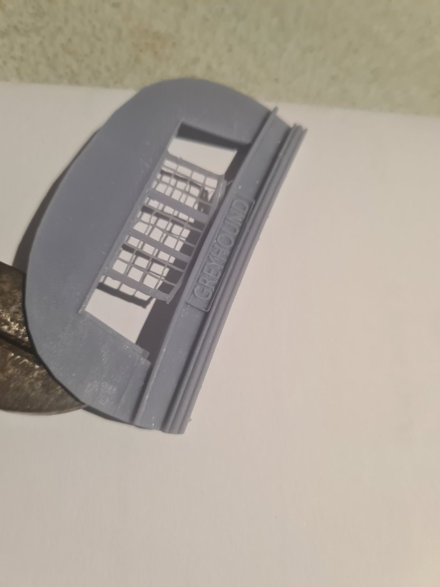
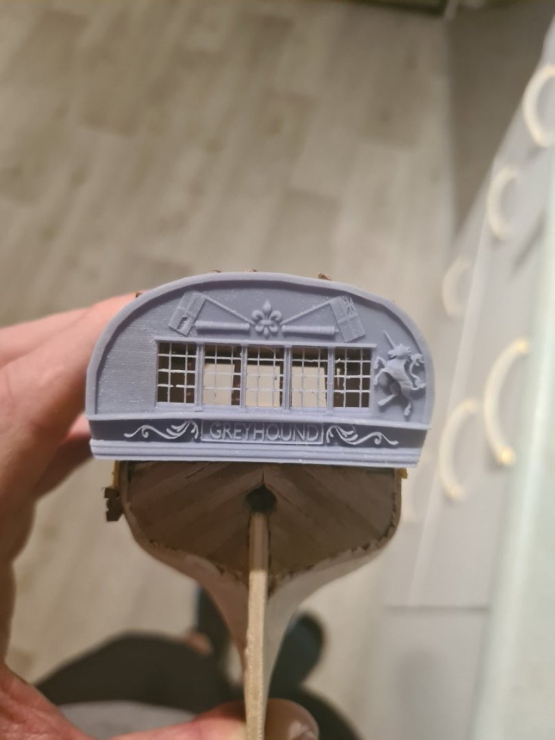
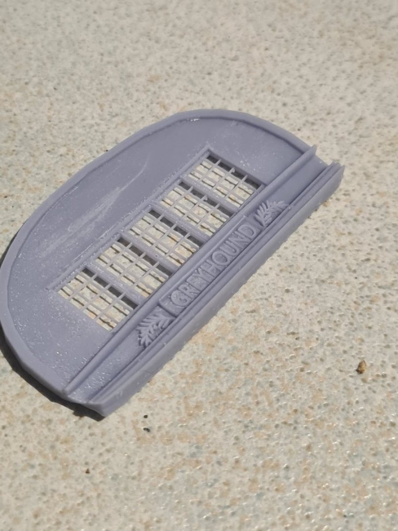
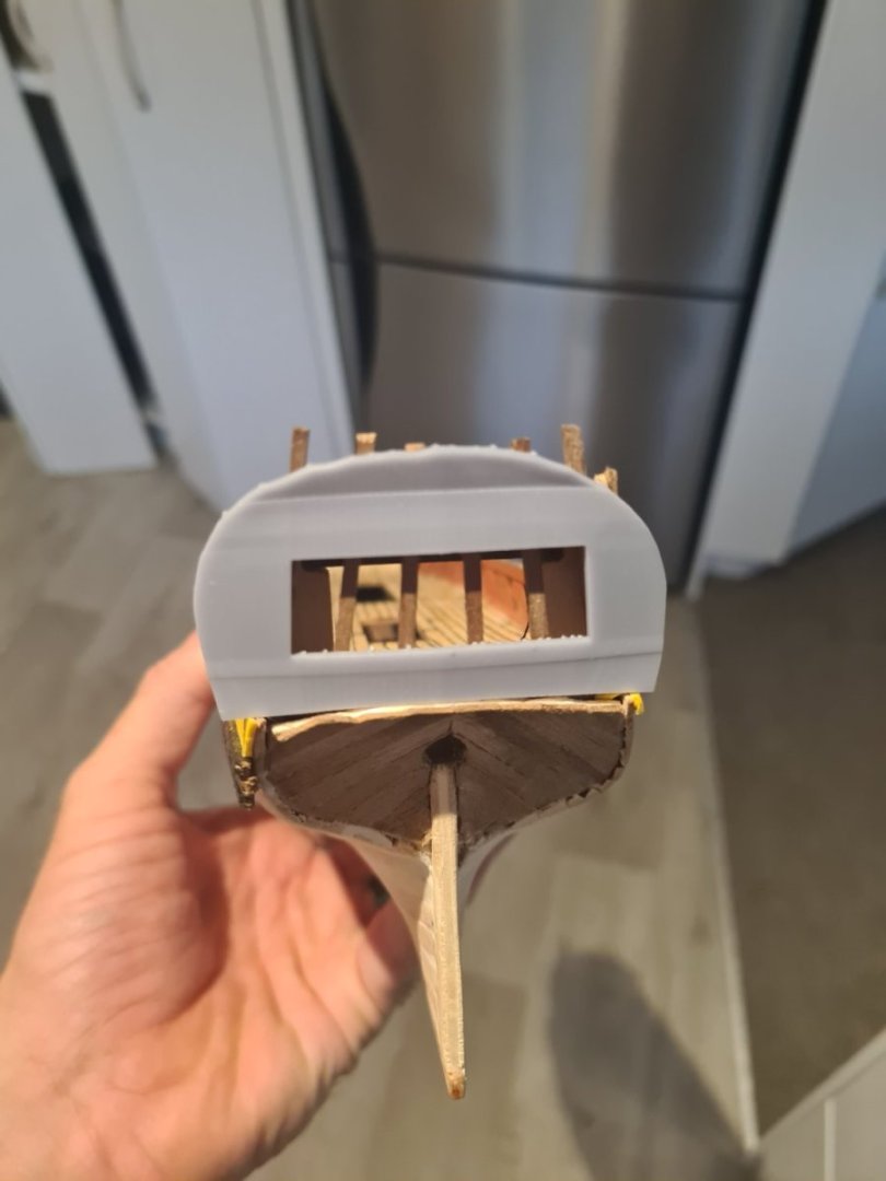
Ok I'm happy with the basic shape now and I was mega rough ripping off the tree... I didn't care I just know I can print all the windows now at the right scale. It's fine so on the final print I will take special care and cure them properly before removing Moving on to the profiles now.. man they are hard taking svg from the internet and trying to 3d them from 2d... not easy!
-
Failed print but also not fine enough detail
Srenner replied to Srenner's topic in 3D-Printing and Laser-Cutting.
What about meshlab? I downloaded this afternoon but man there are so many filters on there my head is spinning... maybe will just try Microsoft 3d builder as well -
Failed print but also not fine enough detail
Srenner replied to Srenner's topic in 3D-Printing and Laser-Cutting.
I'm making progress... worked out I should export as stl file not obj file that helped immediately in chitubox fixing up the graphics there. The print looks like it is refusing to print one cube in the mesh... its not there in final output so its one of those horrible ones where it looks rendered and enclosed on screen but probably isn't or you can see its like a tray filled in on one side only and the sides but not the top..... Which 3d mesh checking tool do people recommend to run before print? The other thing is disappointing that at 1/100 scale the really fine detail that completes something nicely you just can't print out... looks good on the screen but the hobby printer won't go down to that level... unless someone has a 8k or higher resolution printer maybe?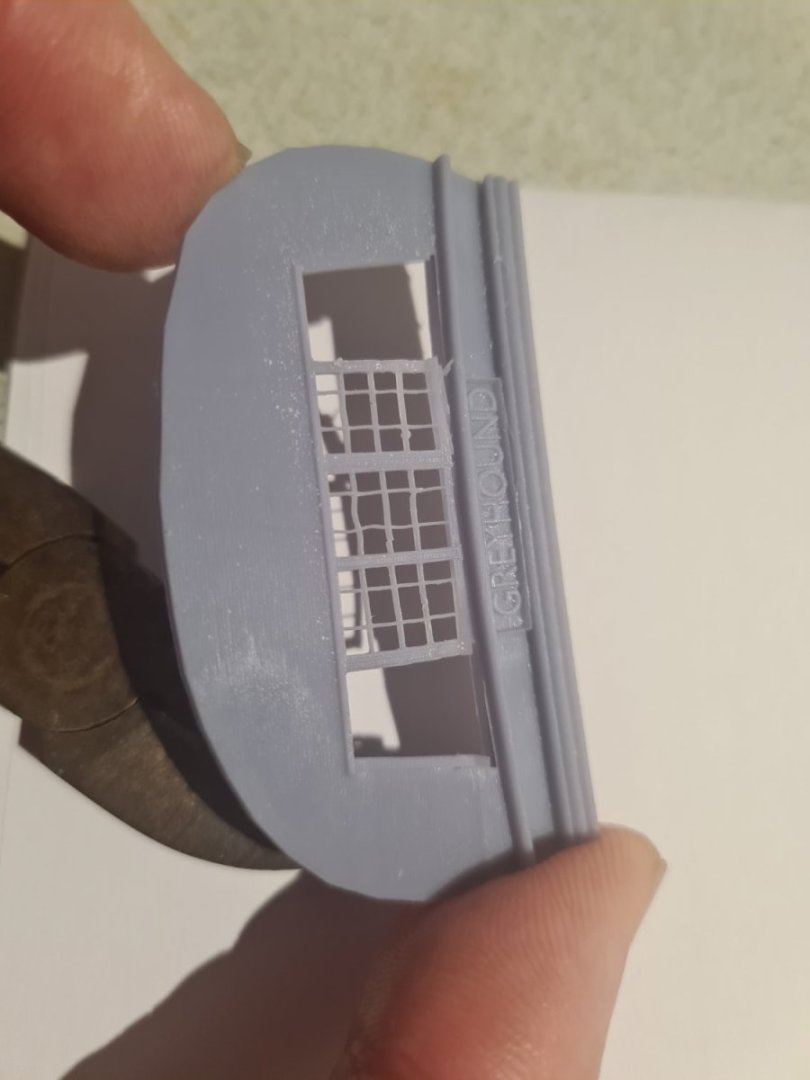

-
Failed print but also not fine enough detail
Srenner replied to Srenner's topic in 3D-Printing and Laser-Cutting.
Hi Question if I adjust the alias it won't round off a single pixel at 40 micron square will it... only vertices and edges of the solid at effectively blocks of 40 micron x lift height set set at 40 micron perhaps -
Failed print but also not fine enough detail
Srenner replied to Srenner's topic in 3D-Printing and Laser-Cutting.
Yes that makes sense... I did the resin set time test when commissioning the machine... you mentioned it would be less for smaller layers? The layer was set at 0.05mm for the test so would it be half the time for 0.023mm? -
Failed print but also not fine enough detail
Srenner replied to Srenner's topic in 3D-Printing and Laser-Cutting.
There must be a problem with my mesh... need to get in there and see if I have not extruded something properly because all the parts I am trying to print are around between say 0.7mm and 3mm so thats quite a bit more than 0.023 mm... but does explain why using solidify modifier (blender) on a curved mesh piece is not a good idea if you want to print as it adds thousands of tiny pixels that can't be printed by the machine... just figured that out -
Failed print but also not fine enough detail
Srenner replied to Srenner's topic in 3D-Printing and Laser-Cutting.
Anytime photon m3 says pixel size is 23 microns so that means a layer height of 0.020mm is less than the pixel size then doesn't it? I might down load lychee and see what that one is like... slicer programs are way easier to learn then blender etc at least at the basic level. -
Hi.. newbie trying to get the printer to go better... I thought all my mesh was enclosed and sunk onto the other parts around it but probably not looking at this print fail Questions: chitubox slicer graphics are pretty poor you can't tell the details of the scaled model very well... it kind of blanks out some of the detail.. are other slivers better at representing an obj file? 2. I had the default layers at 0.05mm will it make a difference going to say 0.02mm for detailing? 3. Do you raise and tilt the model detail away or towards the build plate and let the tree supports self generate? While I appreciate the trees support overhangs etc it still means you would have to file the "good" face or do you support the back face only leaving the good face upwards? Any tips or help would be appreciated
-
Thanks hamilton... I am going to attempt to put some oak texture on there and it will have to be painted of course to make it look good which is also hard... Such an interesting hobby combining wood, plastic, airbrushing, paint effects, computers and 3d printing! And also soldering.. my least favorite part.. oh and sewing.
-
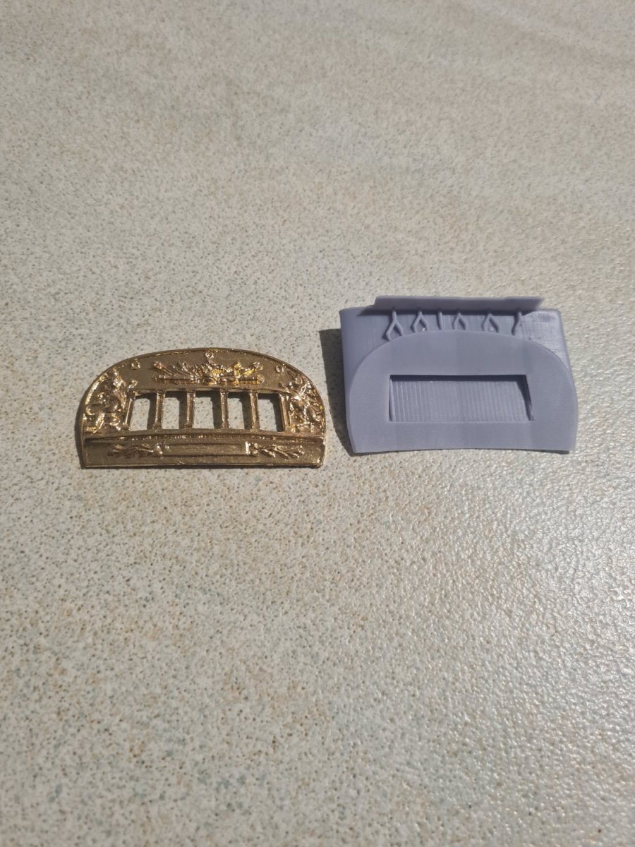
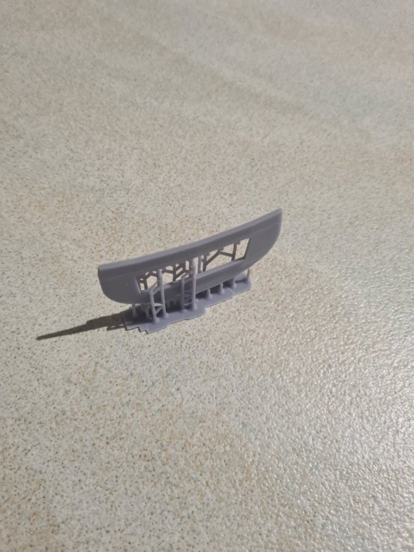
After a nice Easter weekend I got to sit down and do some solid mucking around on blender and I got the start of the stern piece shaped by using some boolean modifiers and importing the image of the piece into an empty. The hard part was filling it correctly so it would print properly... there is mark 1 to mark 3 versions in the photos. I'm happier with mark 3 and I can now start on the decorations like the lion and the unicorn on the sides as well as windows which I will print and insert into the opening.


-
Hi... im getting the same error it looks like now as well

-
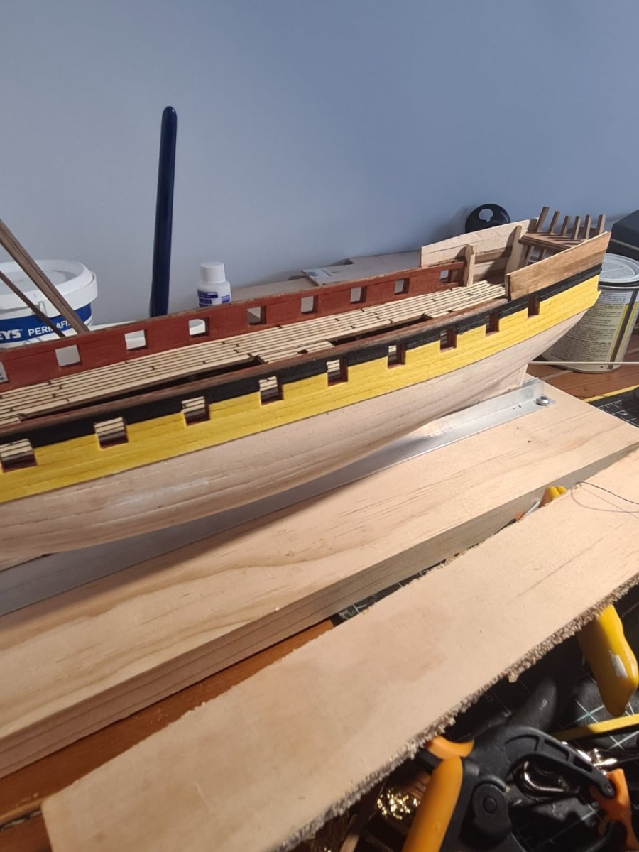
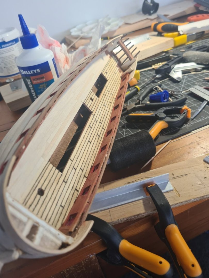
Finished the Wales on one side and now moving to the other one... need to maybe do a bit of sanding just to smooth it but it's pretty good amd also happy with my first lot of 3d printing..

-
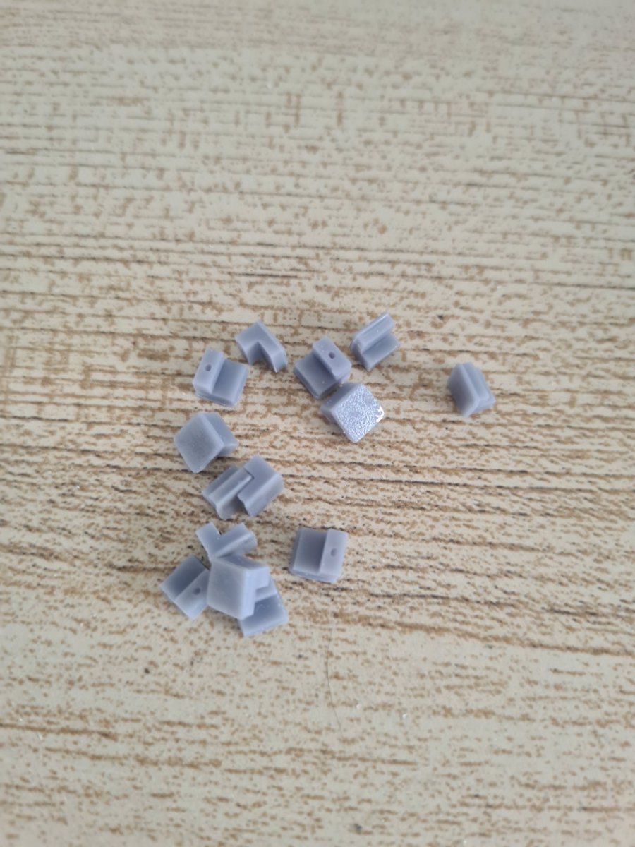
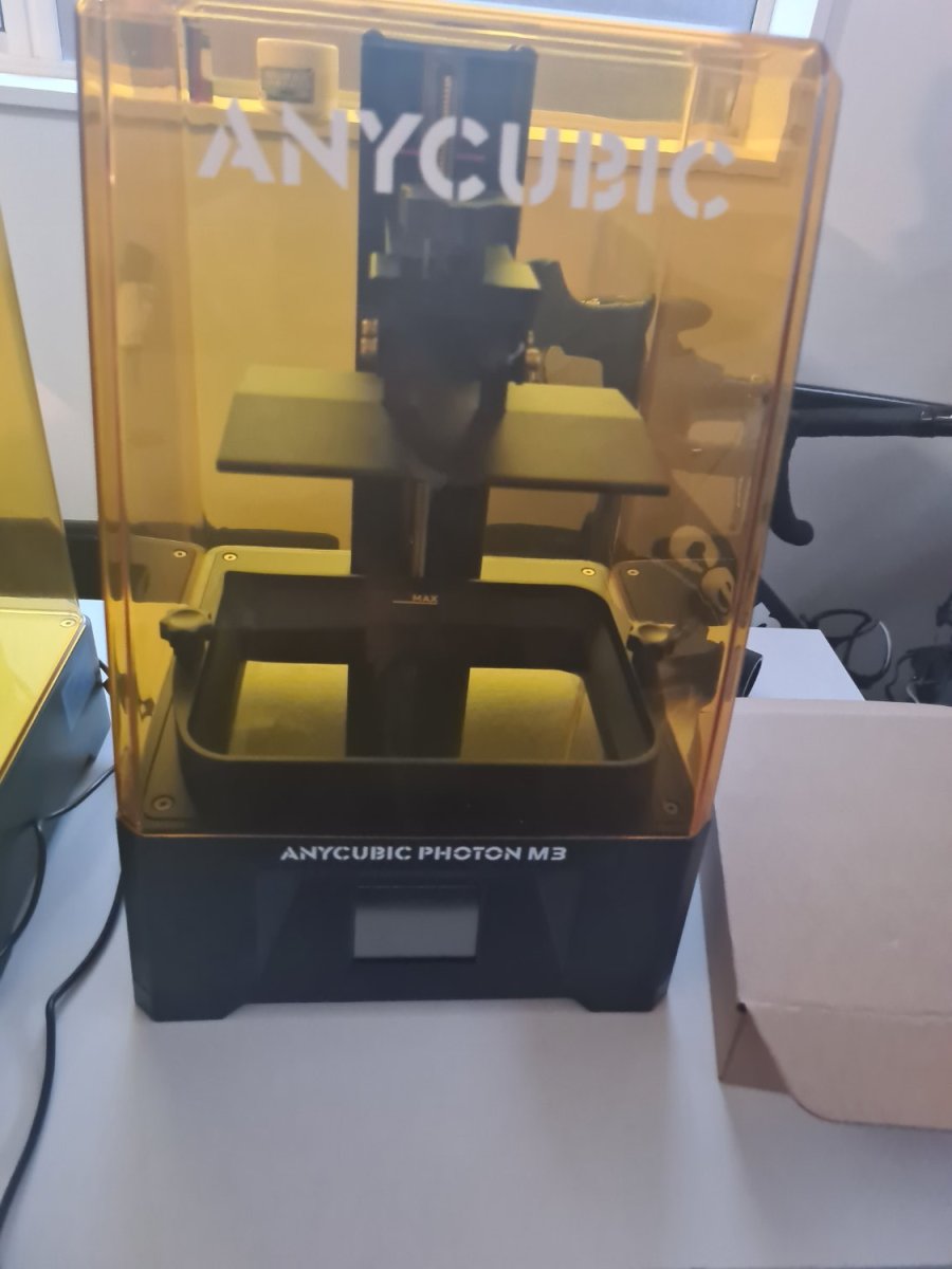
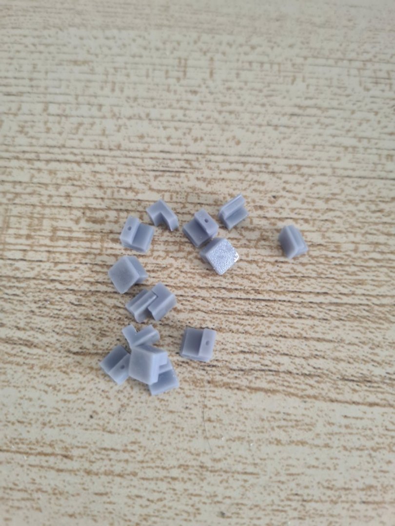
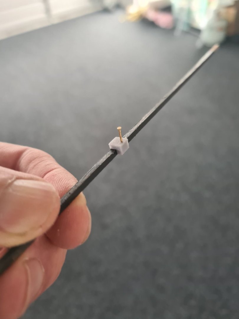
Here is the first output from the new 3d printer... some 2mm high pins sized for the Wales so I can pin them down during gluing. I designed them in blender and exported them as an object into the slicer program and then duplicated about 20 of them across the build plate. Am also going to make some 1mm high ones for the walnut second planking The cool thing is I can keep making them from now... I need to 3d print a little funnel for the resin filter to go back into the bottle
-
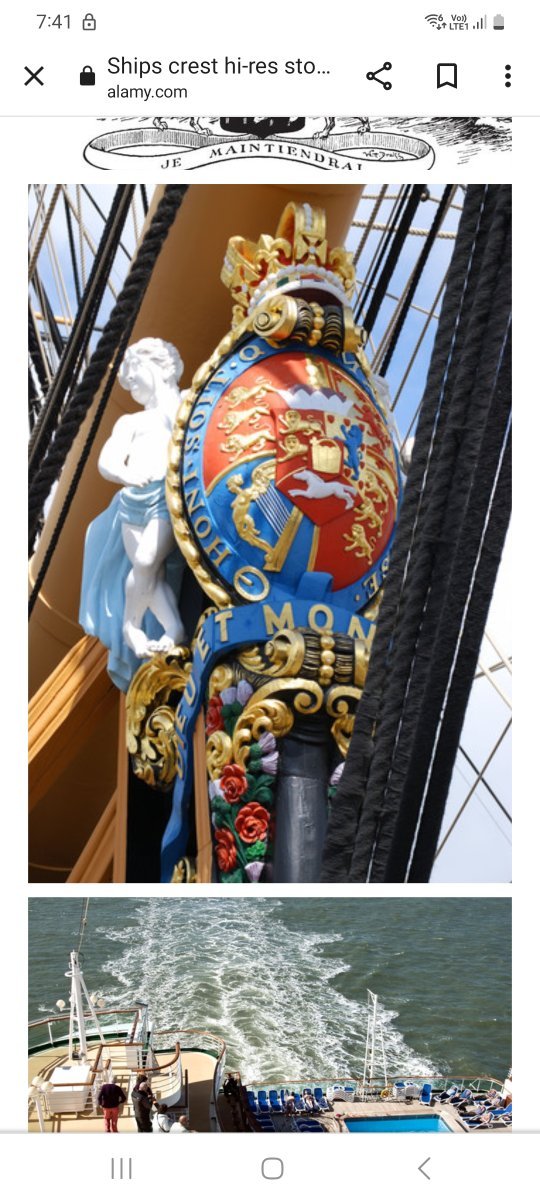
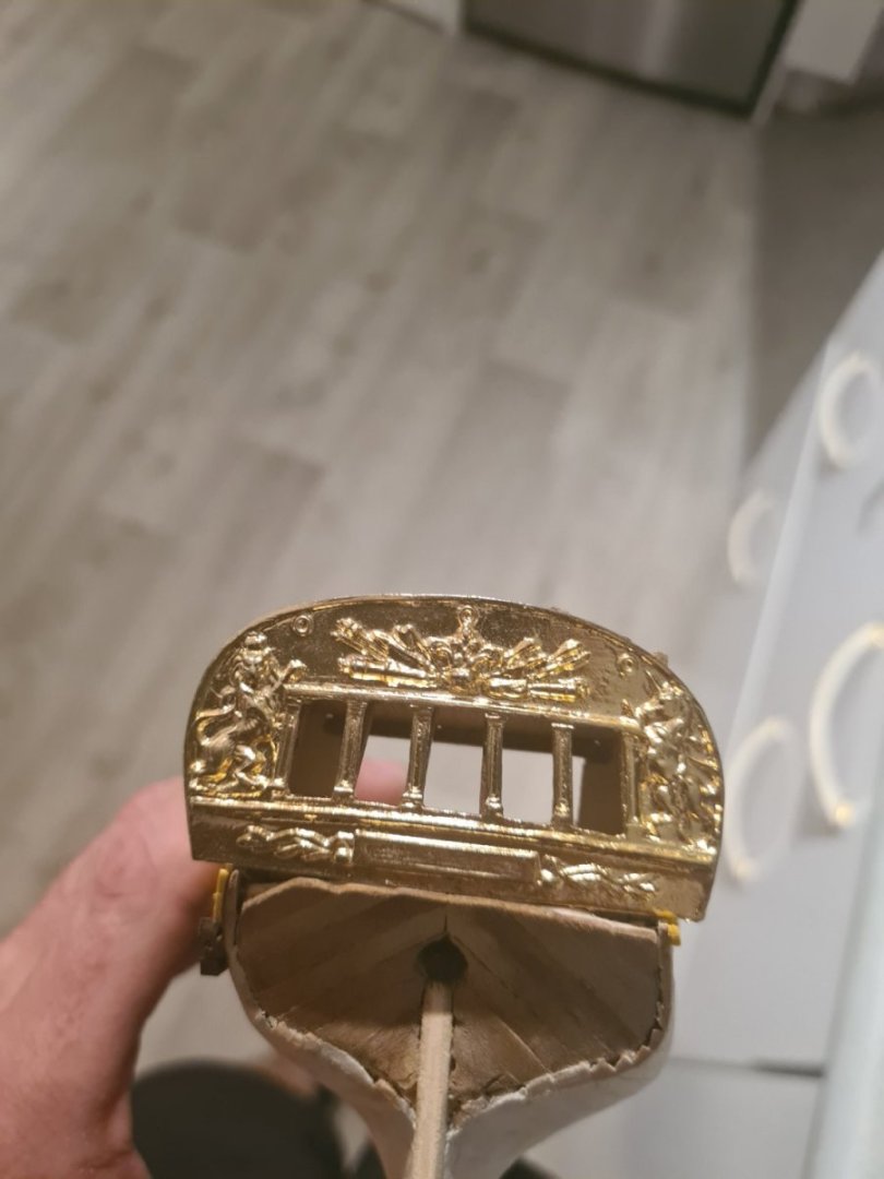
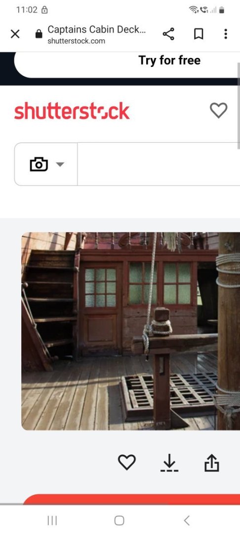
Surprise luck in terms of cabin details... this popped up in my Facebook feed about hms rose and then found her in the ship board models with a photo... so easier to "modify" the Greyhound to be similar without the gilt work

-
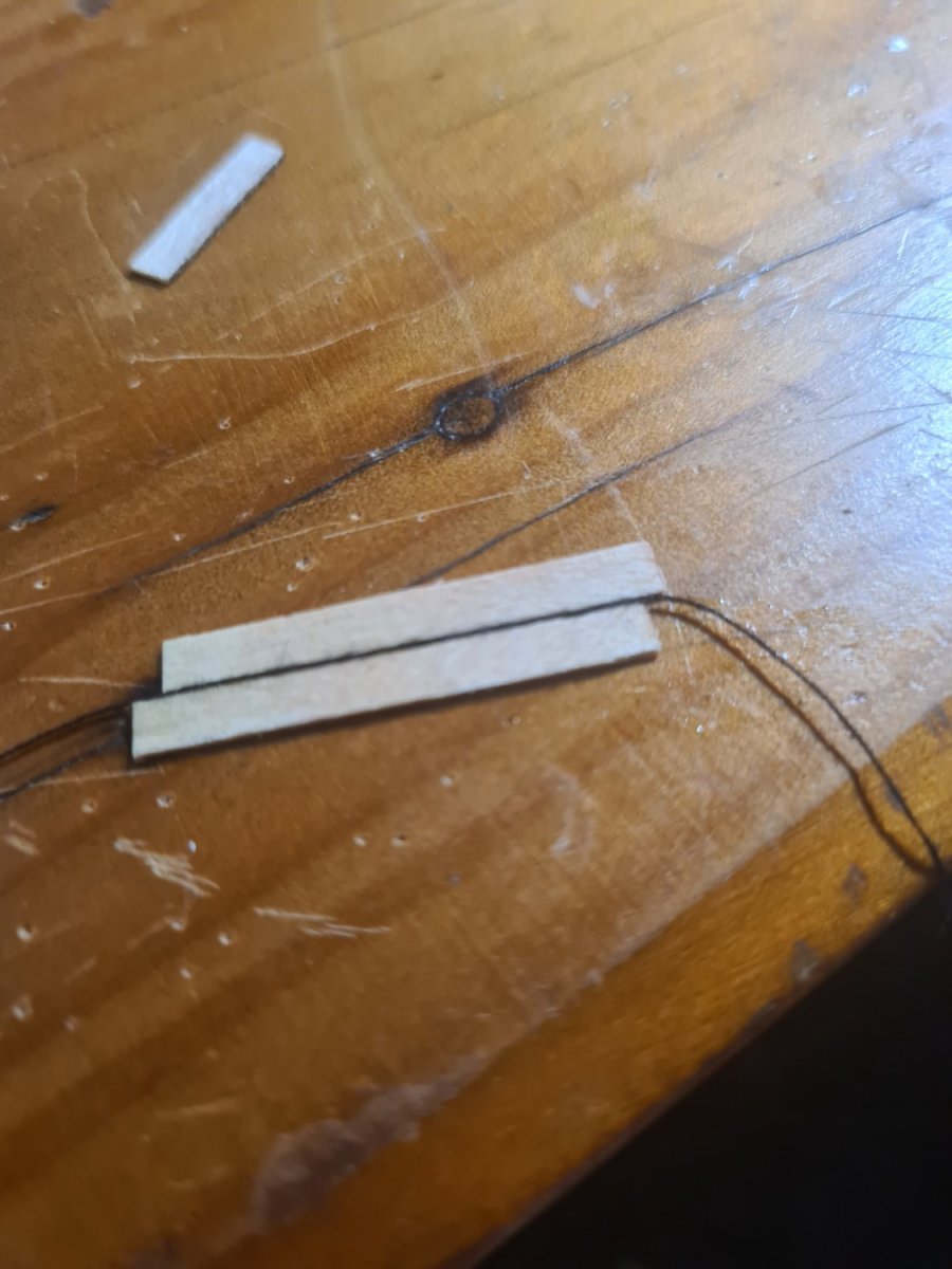
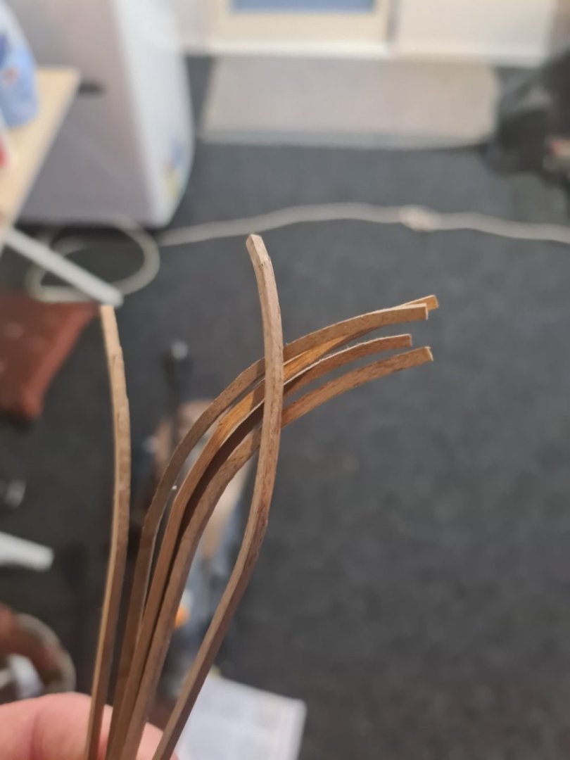
Allan, it is weird especially because the main Wales are painted black... could still be basswood but I tried the chuck method and it was the 2mm thickness that didn't work .but the results are okay today... one stick is split but I will glue it down and it will be alright I think.
-
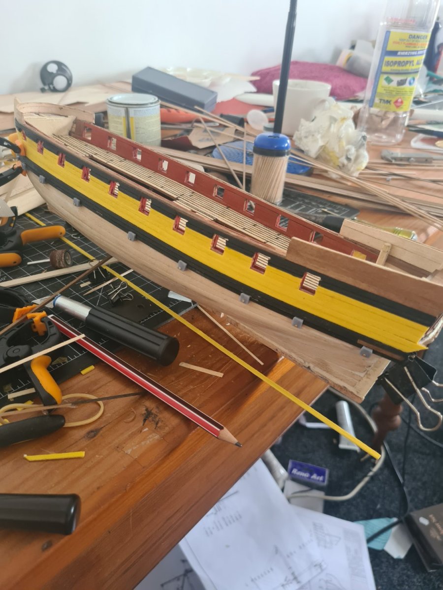
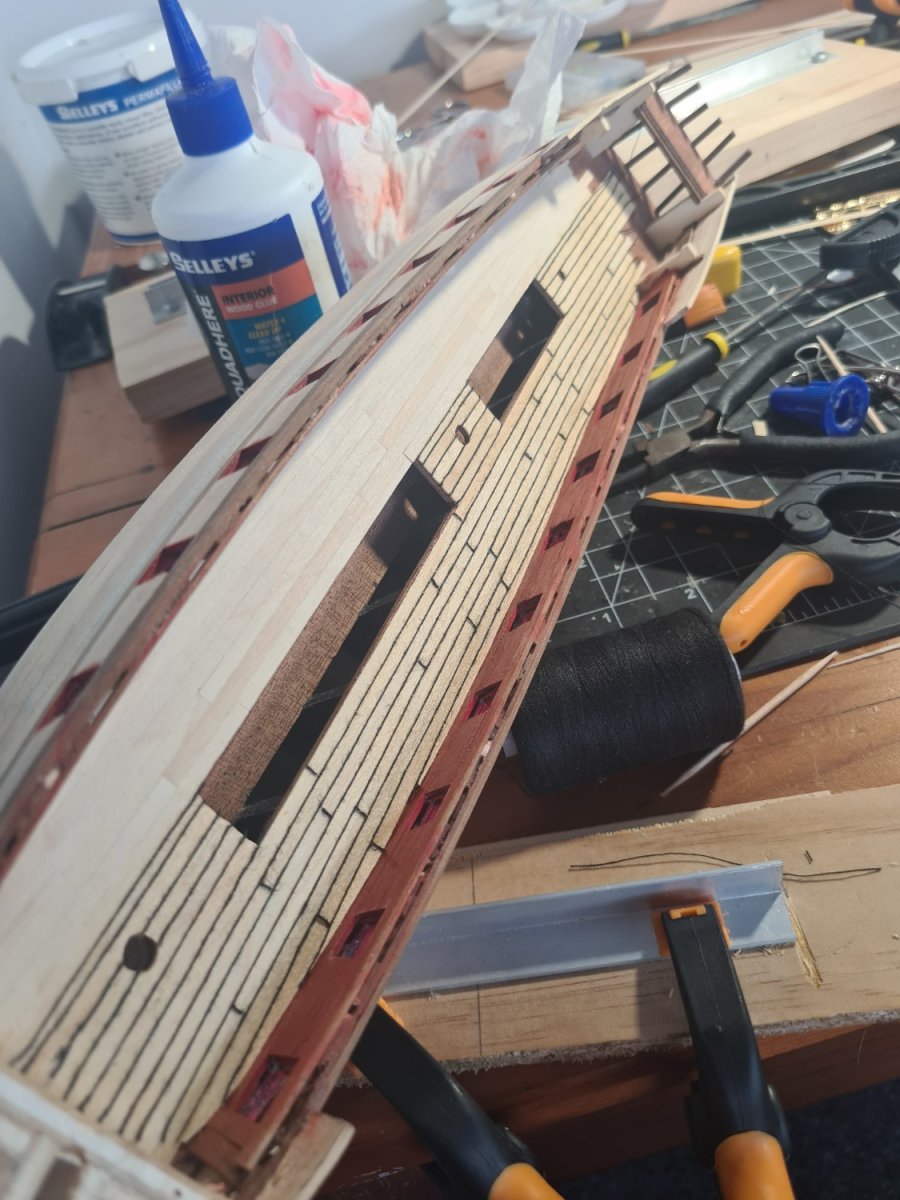
While I'm working on my blender skills (again!) Trying to make some decent windows and things I moved on to the second planking... and things going okay... except for the 2mm x 2mm walnut for the main wales which split when i tried to bend them... now soaking them overnight before trying to bend again tomorrow. And move onto the starboard side before going onto the diminishing timbers below the wales.


-
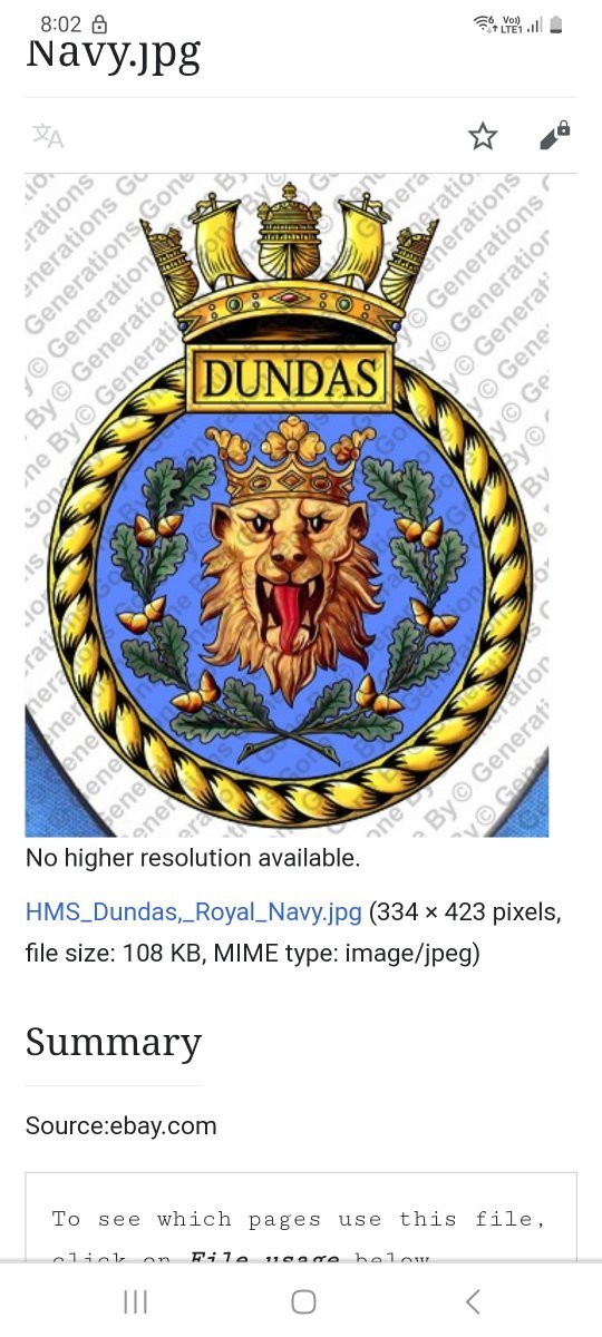
I've finished the decking but my mind is firmly on adding those carbed features to the doors to the cabins in old blender. Really struggling to find good photos of carved features in keeping with 1700s king George ii times. One of course is the royal coat of arms, the other is his initials but also thinking about some of the carving you see around the figure head of hms Victory... what would be appropriate artworks to adorn the tops of frames etc? What about inventing a ships badge just for decoration? Dimond shape for frigate?


-
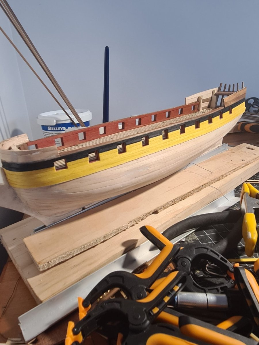
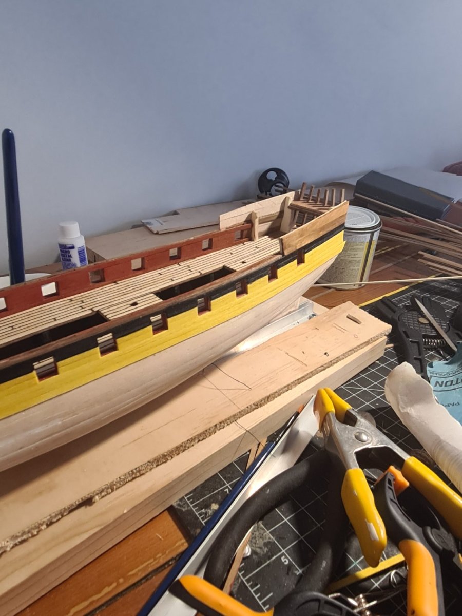
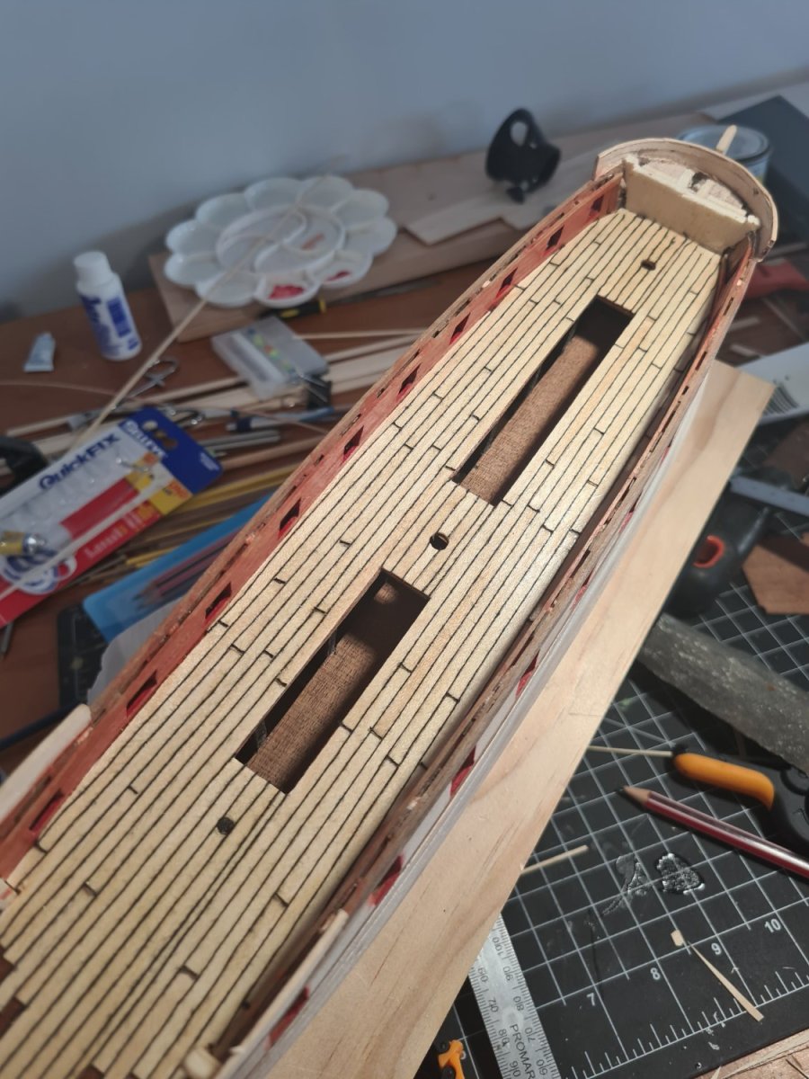
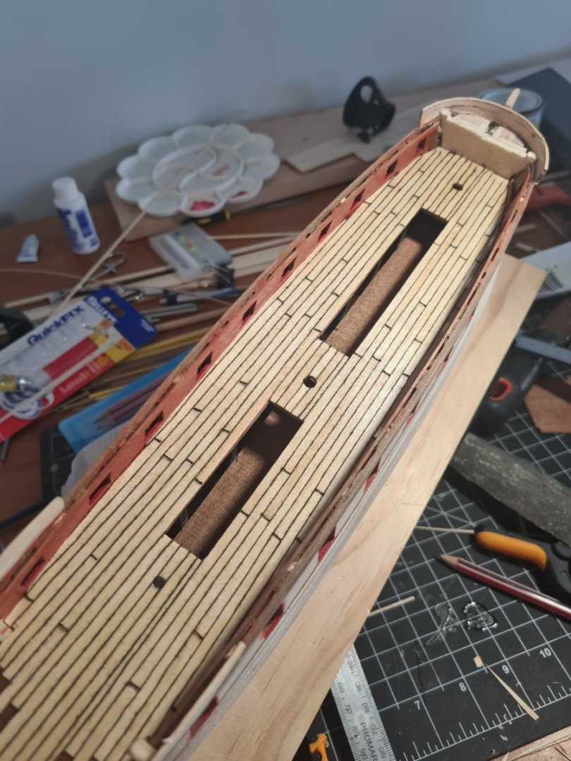
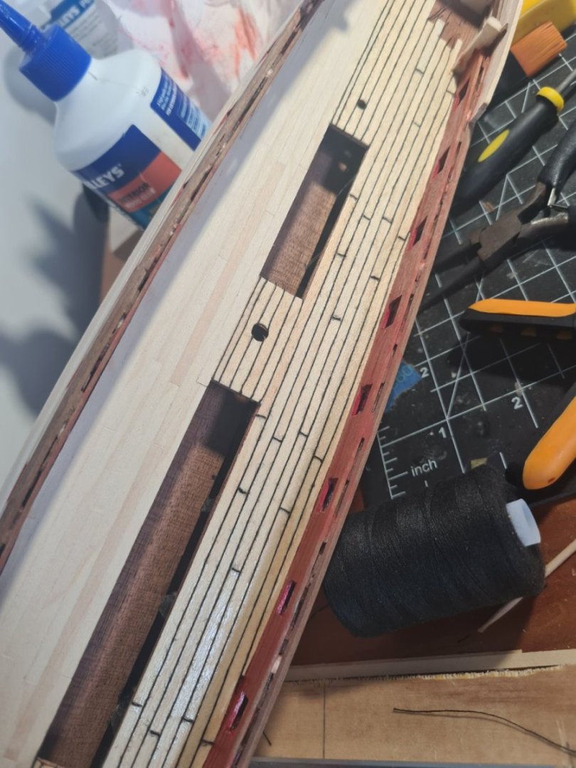
I am making progress with the deck planking but doh.. I noticed I have mucked up the 3 butt pattern! Of course I only noticed it after the deck was laid and glued... and I'm not going to fix it. The cotton makes a pretty bold pattern on the white of the beech but I like the contrast of the white boards made a bit yellow by the shellac and the black cotton. The method is to dot the ca on the butt plank joins and stretch the cotton out until it sticks then use the shellac to stick it all down... I am applying the shellac neat out of the can but I want that yellowing to also age the wood a little

-
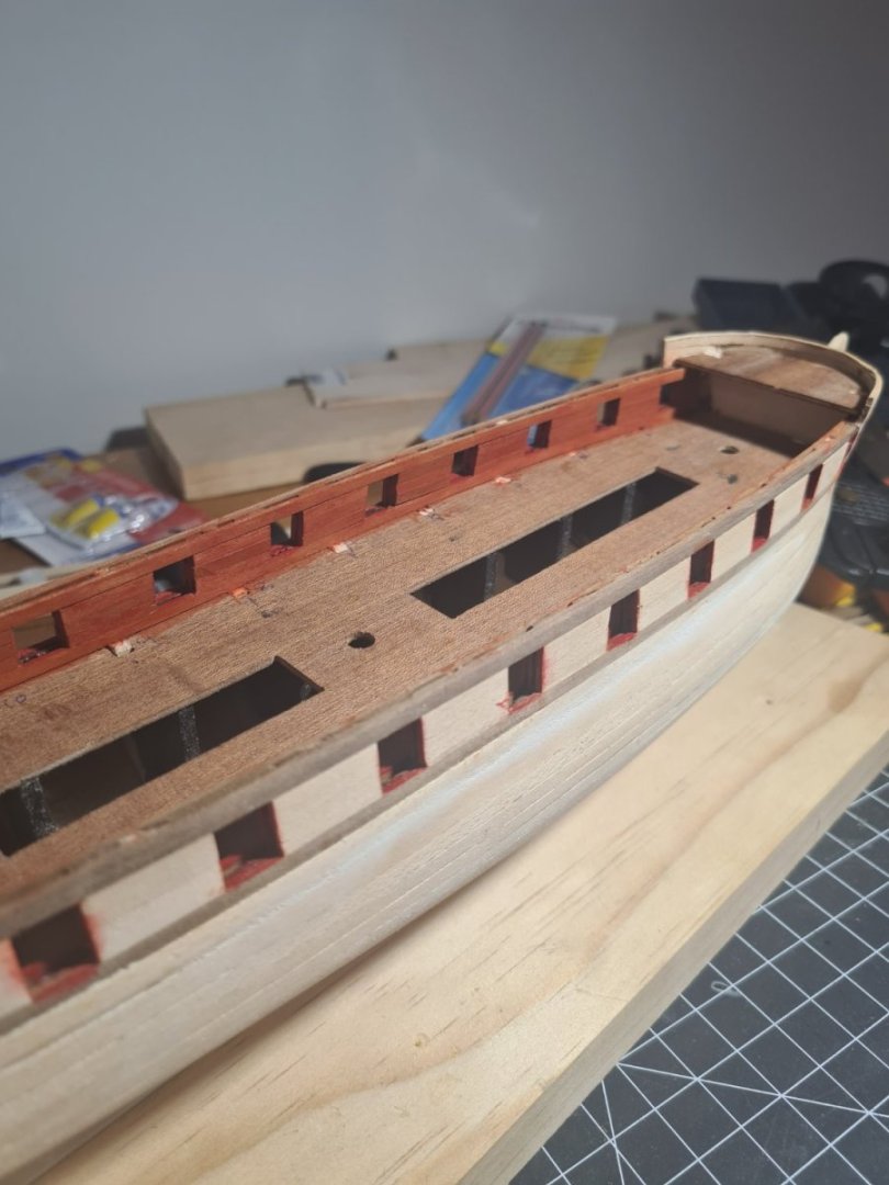
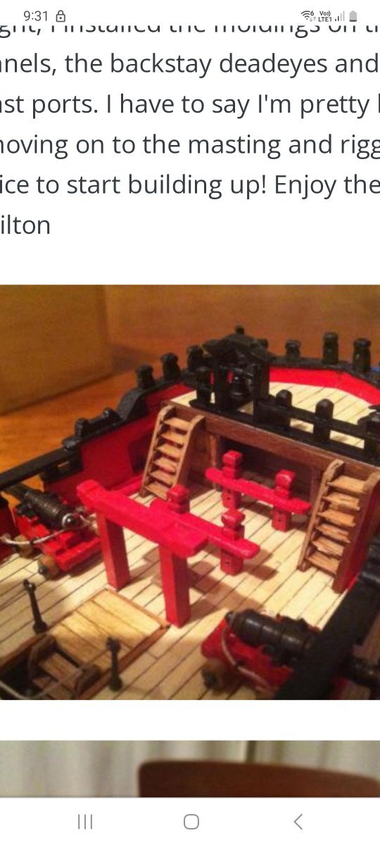
Hi hamilton Looking at your model of the Blandford you put the stairs in front of the foremost gun port which goes under the forecastle overhang. Is that the only way to get stairs going upto that deck into there? It seems logical - maybe they are removable stairs or fold out stairs that can be taken down in action? Did you make the forecastle smaller? I downloaded this picture from the internet today maybe some other ways to go

-
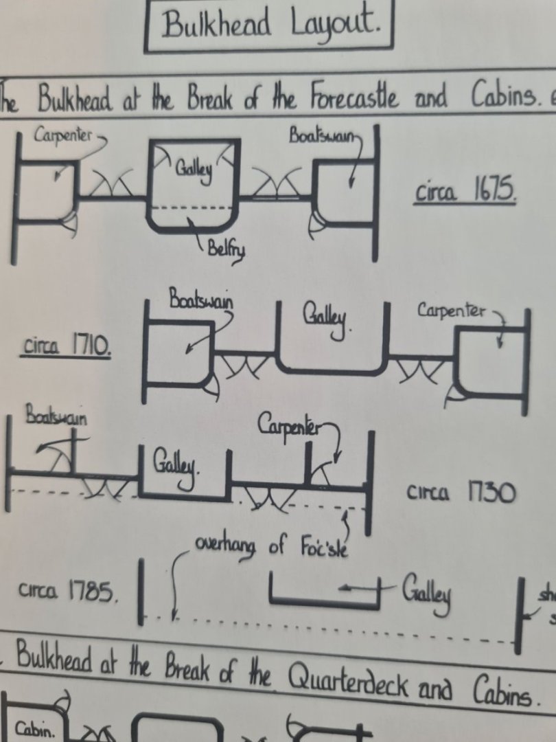
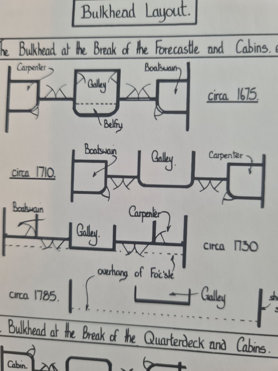
Hi hamilton So your saying keep it square, the galley sticks out under the overhang of the forecastle circa 1730 design?... probably easier as the forward gun port is also partially under the forecastle deck
-
Hi... is there an article on here explaining the best way to use the cotton thread between deck plank method? It just looks stronger line than the pencil edge which I tried hb graphite or should I go for charcoal pencil instead? Any help appreciated thanks

-
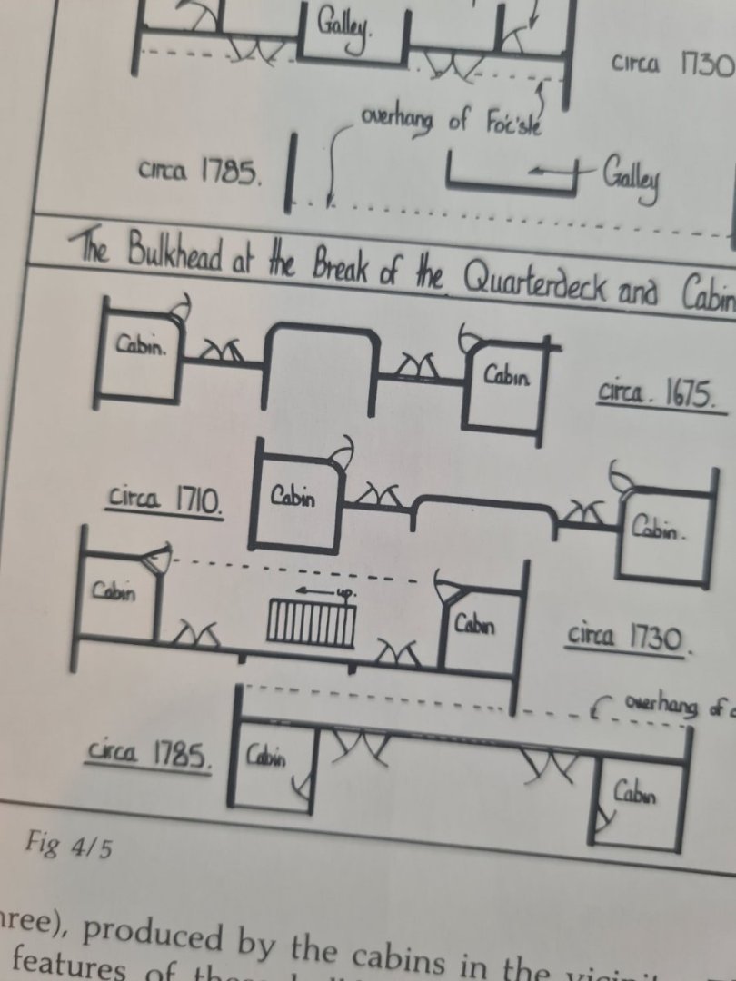
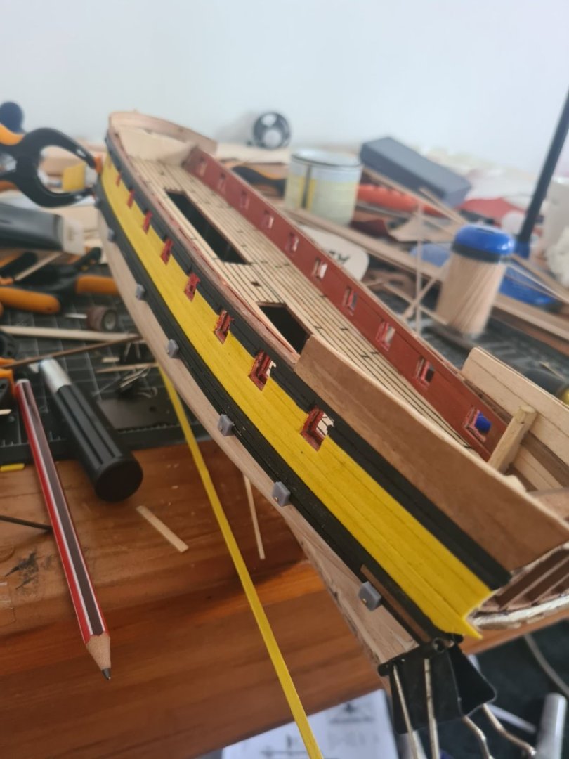
Been working on the red ochre or dark red paint colour for the timber on the main deck sides... its a little bit of a issue... I know the traditional colour is red ochre but it's not a great colour and bright red would look better but I also liked just the timber look. I was going for a washed out colour that you could still see some of the wood grain coming through so I diluted the red ochre and dry brushed some red over the top. Changing tack now and going to try 3d print the walls under the forecastle and the quarterdeck. According to the Goodwin book it should be a straight wall for 1730 style but I like the idea of it being curved and that could be easy to do with the printer. What suits this age of ship more?