
HOLIDAY DONATION DRIVE - SUPPORT MSW - DO YOUR PART TO KEEP THIS GREAT FORUM GOING! (89 donations so far out of 49,000 members - C'mon guys!)
×


Jaager
-
Posts
3,084 -
Joined
-
Last visited
Content Type
Profiles
Forums
Gallery
Events
Everything posted by Jaager
-

sealing solid hull
Jaager replied to lionfish's topic in Building, Framing, Planking and plating a ships hull and deck
If it is intended to adhere to glass,then poly will provide a plastic surface that is about as close to glass as can be had. You probably want to give the surface a good rubdown wit 0000 steel wool, before, between and after each coat. Vacuum and tack rag the dust and steel fragments throughly after each treatment. Any steel left can rust and stain. 600 grit Silicon carbide paper may be a good alternative to steel wool. -
sealing solid hull
Jaager replied to lionfish's topic in Building, Framing, Planking and plating a ships hull and deck
Having had bond failure between Weldwood contact cement and flame treated copper plates - a method in the 1970's Model Shipways catalog - investigate the best conditions for bonding with your chosen adhesive and use that to determine what treatment to give the hull. It has been a very long time since I saw the brig Eagle hull, but as I remember, the cement under the failed plates was copper colored, making it difficult to tell they were missing. I suspect the heating process produced a micro layer of a copper oxide that was not compatible with Weldwood. I also use it to attach cloth backed sanding medium to the platten of my thickness sander. A heat gun makes for easy removal of the spent sanding medium. I suspect that Weldwood is medium time frame adhesive. My present thinking on coppering is to use a high quality archival smooth surface paper painted with copper and verdigris shades and use PVA to attach it to a raw wood hull. -
My first thought was snarky- especially for the English shipwrights: Why do a simple butt joint when you can do a scarph? Then thinking about it - the structure is subject to constant motion and stress in all 4 dimensions - though the effect of Time is much more gradual. A straight butt joint would be difficult to fasten in a way that was not subject to early failure. Quick research answer: Not a butt joint or a scarph - a third element : a lateral knee was worked in. It spanned about 1/2 the width of the rail timbers, each arm would be long enough to support a couple of horizontal trunnels into each rail segment and the inner surface would be an arc rather than an abrupt meeting of two planes.
- 1 reply
-
- 3
-

-
For ways and static surfaces, I am now using Renaissance Wax. For the threads and general lubrication, I used to use light machine oil. I had a quart from Sears that I used up. I could find nothing like it on line. I guess I do not know the correct name for it, I use mineral oil from the laxative section of a pharmacy for lubrication now. No problems so far. Used to be light and heavy Mineral oil available, now all I find is plain mineral oil. Using a Scotch Brite Pad with WD40 works a champ to remove rust before rubbing down with the wax.
-
To you guys in the UK : There is a hardwood that should be readily available - Sycamore maple Acer pseudoplatanus It is very similar to our Hard maple (sugar / rock ). It was a species favored by Underhill. Because of the difference in local vernacular, I got a supply of Sycamore from a sawmill in Eastern Kentucky. Alas, Sycamore here is a different species in another genus Platanus occidentalis. For our purposes, pseudo platanus is better than actual platanus. Our version is less dense, is a lot more brittle - more readily splits - gets fuzzy. It is also sold as lacewood because of it's ray flecks - which at scale - presents something that looks like nothing in nature. Looking at lumber prices in the UK - from what I can see - the prices are outrageous - they really see you guys coming. If you have local furniture makers, I would visit and see where they get their lumber - they may even have cutoffs or surplus you could get a deal on.
-
From Longridge extolling the virtue of the Midget Universal, I went looking for a similar machine and found the Unimat SL. I in no way regret it. It is a well built machine. It is a joy to work with. I used the lathe function to produce shaft adapters using cold rolled steel stock. It was a total PITA to tear down the ways and slide table to remove the steel shavings. Everything comes apart and back together just like the precise machine that it is. I coated the ways with Renaissance Wax, which seems to be a good thing - protection from rust, waxing the threaded rod - not so wise. The tolerances are so close that it took a lot of cranking to remove enough to make the feed wheel turn easily again. It is nice to be able to use it to make other machines. I got the lathe duplicator (the generic one) from Penn State for turning cannon but have not tried it yet.
-
Gunports
Jaager replied to piperck's topic in Building, Framing, Planking and plating a ships hull and deck
You are your own shipwright, if you wish to mount a plasma pulse cannon on the deck, you are free to do it. Anachronisms and additions without reasonable documentation tends to drive those with a historian tendency berserk. No matter as long as you are honest about what your model really represents. It would not pass muster in a competition, most likely. -
Gunports
Jaager replied to piperck's topic in Building, Framing, Planking and plating a ships hull and deck
Since POB does not mimic original methods, you have some room to play. I would do it like this. Before the real outer planking is applied, locate all of the gunports. Get some hardwood stock that is about 4 inches thick in scale. 1:75, right? So about 0.05 inches thick. Use this to make a "picture frame" structure for each port. So widen the port by 0.05" top/ bottom/ each side. As you look at the side, the frame will be 0.05" each side. The depth will be determined by what is there. Fit the lower and upper sills first, then slide in the side pieces (frames - or timbers scabbed to frames). Make the framing flush with the first planking layer. For the outside planking, look at the plans and see if the port lid had a lip on the side ( a recess in the planking ). Some vessels had this and some had the edge of the planking flush with the side port framing. You can always plank flush and chisel in the lip later. Inside - is it that there is only 1 layer of planking? If so, only cut the actual port opening there and butt the port framing against that layer. -
I have had mine since about 1972. Had to replace the motor. Burned it out using it as a table saw. I have replaced that function with single purpose machines. I got an additional aluminum bed on line with the intention of isolating the post holder portion and positioning it about 1/2 way down the bed to have a mill with more work movement options, but I have not gotten up the courage to wreck a part that is no longer being made. Where do you get your belts?
-
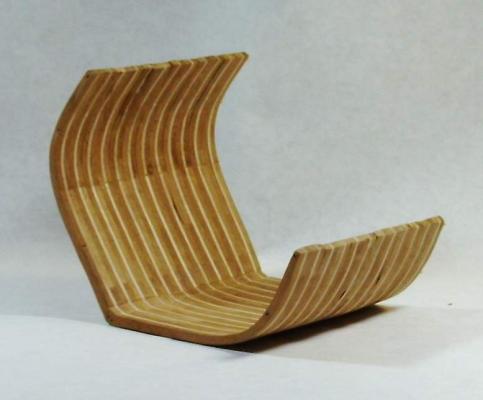
It looks like it could be a pond yacht. One that actually sails. The keel / rudder does not match any of the competition models in my copy of 1985 Model Boats Plans Handbook. It may not be all that incomplete. It has more deck detail than the competitor types seem to have, but less than a static model. It may be a fun sailing boat with just enough detail to make it interesting when seen from a distance. The sails and rigging may have been lost, as they were probably stored separately.
-
I would think a hand fret/coping/jewelers saw would do the trick. Blades are easy to find in the 3-8 range. There are variety packs. I think for basswood, you need very sharp edges to avoid tearing out the wood fibers. It is like a scroll saw, except that you are the motor. You should find something functional for less than $20 US.
-
It is on my wish list. When looking at Cog models ( which I thick of as an immediate ancestor of Mary Rose ) the construction of the castles brought a concept to mind: the hull up to the main or upper deck (depending on ship size) was built by shipwrights. the castles were added on by the craftsmen who built land based castles and other buildings. The general lack of curves and the general components do not look like a shipwright's work. Practically, I don't think they needed the particular skills of a shipwright. Another thought, if a merchant ship was drafted as a warship when needed, the castles could be a temporary addition.
-
Steam tool for bending wood model ship planks?
Jaager replied to mobile1's topic in Modeling tools and Workshop Equipment
A vegetable/rice/food steamer cooker should do the trick. Black & Decker and Oster both have long oval models for < $40. They are also useful for cooking rice and veggies, so be more cost effective than most tools we buy.
-
BOATS OF MEN OF WAR MAY,W E NIP/Chatham 1999 describes an interesting addition: two tubular trunks, one on either side of the keel at the windlass, thru the bottom of the Launch. Ropes up thru the trunks to the windlass could lift and hold for transport - anchors and cannon. A solution to a potential tipping or stern dipping problem. Investigation of this was begun in1818.
-
Ulises, 100/3 , 80/3 , 18/3 are the size of the linen in an old standard termed LEA. 18 is much larger than 100. It is the yarn size. Fibers twist into Yarn twist into Thread (or model rope) twist into (for our purposes) Rope. 62/1 is a linen yarn. It is a single unit of twisted plant fibers. 100/3 is a linen thread. It is three 100 yarns twisted into a three strand thread. Linen is much more coarse than cotton. Most linen yarns are much larger than cotton thread. The 62/1 linen is not much different from a #100 cotton thread. The whole subject of rope size can be confusing. Rope is subject to compression, so "micrometering" it does not give reproducible results. The most common way for us to measure size is to wrap a section of the rope around a dowel (closely packed, but not extreme) and count the number of revolutions in an inch. This gives the rope diameter. The reference books like Steele have tables of sizes - as rope circumference. Take our diameter measurement and multiply by pi (3.1416..........) to get the circumference. I suspect that there are models out there with rigging that is 3 times out of scale.
-
I have been around this for a while now. But even when I started linen yarn was difficult to obtain. The Cutty Hunk company had gone out of business and the survivors of the owner had thrown the stock of linen fishing line into a dumpster. Frederick J. Fawcett seems to be gone. I collected a good supply in yarn over the years, so I am set, but my recent supplier WEBS - no longer stocks any. The finest I have is 62/1 LEA. I see that there is a 100/1 LEA but I can't source it. But then, the 62/1 tends to break in my Byrnes ropewalk before I can lay up a good length. The 100/1 would probably be a nightmare. Looking on line, all I see now is a Chinese company that seems to buy everything that Europe produces and wants to sell shipping container quantities. How would someone beginning now obtain a supply?
-
I have read that small compressors have a problem with the air pulsing. Would this be mitigated by having an air storage container in-line between the compressor and air brush? Would an air tank used in automobiles to re-inflate tires serve as an in-line container? Would an empty propane grill tank work for this. Until the residual propane is gone, it would be an outdoor only use I am guessing. One possible problem: It is possible for gasoline vapors to make a mixture with air at a concentration where the temp required to start oxidation ( explosion) is near ambient requiring no spark or flame (spontaneous combustion). This also happens with grain dust and cotton lint. Is propane subject to this in pressure + air + available temp range? I would guess an explosion in a 20 gal propane tank could produce an interesting result.
-
I have a suggestion: First, why: Rigging is totally exposed to the atmosphere. This planet is enveloped in a layer of a highly reactive ( and looked at objectively - a very poisonous ) gas = Oxygen. You can readily see it effects on iron - almost as you watch. An acidic pH only enhances its reactivity. CA probably oxidizes - it likely continues the chemical reaction that produces its function ( it needs water - which is certainly present in the atmosphere ). The polymerization can continue until near complete - producing a material that is brittle. Titebond II - yellow PVA - has is pH 3. This is 10,000 x's more acidic than freshly distilled water. Weldbond - white PVA - has is pH 5.5. This is about the same as normal water - which is actually a dilute solution of carbonic acid ( atmospheric CO2 disolved in water). I suggest using something like Lineco White Neutral pH Adhesive. It is a PVA used by bookbinders and preservationists. Dries clear and can be diluted in water to soak into natural cellulose fiber rigging. It does not do do well with plastic, so if you rig with nylon or other synthetic products, use another material. One property of plastic rigging material: they are formed thru a chemical reaction = polymerization. long chain molecules are bonded to short ones - producing a web or mesh. If there is enough linking, a strong flexible material is produced. If there is too much cross linking, a rigid, brittle and weak material. In the presence of UV light, oxygen and heat - plastics continue to cross link on their own. The material will ultimately shatter. Linen, on the other hand - I believe they are finding 3-5 thousand year old mummies still wrapped in functional linen fabric.
-
Ship Drafting
Jaager replied to mholmberg's topic in CAD and 3D Modelling/Drafting Plans with Software
You do not provide much information about your purpose or goal. One place to start - and this is about designing a 17th century English warship - using methods of the time. From a copy of DEANE'S DOCTRINE OF NAVAL ARCHITECTURE 1670 LAVERY,BRIAN CONWAY MARITIME PRESS LONDON 1981 (Among other places, Amazon has links to used copies.) Follow the exercises that Anthony Dean presents and it will give you the grounding that the 18th century designers and copy draftsmen greatly expanded and refined - and the 19th century further polished. It would also help to get several plans from The Smithsonian - $10 / sheet usually - if late 18th to mid 19th century is your interest. In France L'AAMM has plans for sale at not unreasonable prices - covering 17th to 20th century. The most extensive collection is in England - NMM - but the cost - well you better be in love with the vessel. And a lot of the lines - well, they did not have much of the Science, so they were flailing around - trying to find the formula to predict the sailing characteristics of the various hull shapes. -
For a deck, I skip the Tung oil and use only shellac. It is easy enough to buff the surface if it is too glossy. Shellac is the classic base for most any other non water based finish - paint or clear. I haven't gotten there, since I found out about it, but I think the last layer will be a rubbed on coat of Renaissance wax. I doubt the process would be very interesting as a pictorial. One promising thing - I finally got a picture that I can look at from my digital camera. It was the first I took from a distance and not macro. Who knew? It is the midship section framing of USS Porpoise 1836 - designed as a schooner - rigged as a brigantine and later a brig - The last few years, I have been developing a (new?) way of framing a hull that I call The Frame Sandwich Method. I am just not sure how to present it.
-
Flying my true colors, I have a bias against plastic or anything synthetic on my wooden ship models. This does not extend as any prejudice against the work of others who do use these products raw wood - sanded 220 -> 320 -> 400 -> 600 and then scraped with single edged razor blade - rubbed with shammy leather cloth 1st coat pure Tung oil cut 1:1 with mineral spirits. 2nd coat straight Tung oil. 3rd coat super blonde shellac flakes made into a 5% solution in 100% 2-propanol (isopropyl alcohol) [ 10% solution diluted 1:1 ] 4th coat 10% shellac. 0000 steel wool between coats. Be sure to remove all of the steel fragments - they will oxidize and stain the wood.
-
Something to consider for keeping carving tools sharp: Get some pieces of scrap leather from a local shop that works leather. Coat the smooth side with Flexcut Gold Polishing compd. It comes as a stick - use like a crayon to coat the leather. Strop the edge frequently - pull the blade. I must sometimes move the blade slightly in the cutting direction when I place it on the leather - I can tell because it messes up the surface of the leather. Several back up pieces of leather is useful to have. Unless you mar the edge of the tool by hitting steel or something, you should not need to use a sharpening stone ever again. Stropping should be enough.
-
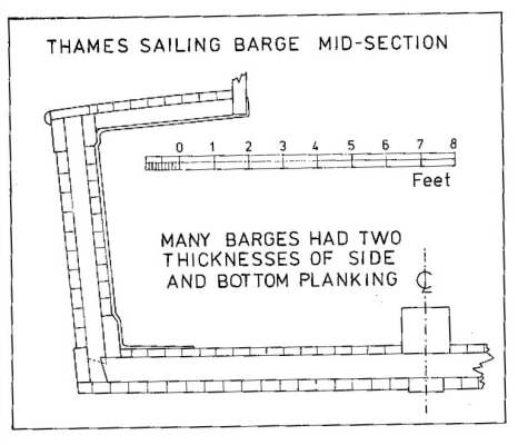
From: WORKING BOATS OF BRITAIN MCKEE,ERIC CONWAY MARITIME PRESS LONDON 1983 BOATBUILDING 224
-
Suggestions: Draw your grid on the white side of a piece of thick poster board. Tape a piece of transparent drafting velum or a less expensive substitute: Bienfang Designer Grid Paper, 50 Sheets, 8-1/2-Inch by 11-Inch Pad, 8 by 8 Cross Section ( $7.00 at Amazon ) The lines are straight and the grid perpendicular, but the grid is not precise. The center line, keel line and base line transferred , but you can leave off the waterlines and buttock lines for each frame - just the frame points are needed. Only plot one side of the frame. Scan the half frame into your computer. Have a transparent metric ruler in the scan. Open the scan in a drawing program - Photo Shop - ( has a rental online deal - if you are quick, you only need a 1 month rental) / Paint Shop Pro / I use Painter 12 - older versions like Painter 8 work just as well - I just needed 12 to get PNG in/out. The program needs layers. Open the half frame as a layer, duplicate it, flip copy horizontally and position the baseline/ centerline and combine the two layers. You now have a precise mirror of the half frame. Kate Cory would probably be framed French/American style - paired frames with the space between +/- half the thickness of one of the pair. I round - I am working on USS Vincennes 1825 R/S is 26" Given the range of sided dimensions of the frames I chose to make each frame 10" and the space 6". The point ? You can use the middle frame shape layer for both outlines of the pair. The metric ruler part - scan in - print out - can be altered by the computer- Matching up the print out of the ruler with the ruler- the % change in document size needed to be done in the drawing program to get identity in size is easier to calculate using metric an English scale. Another advantage - colored lines are easier to follow when cutting out and shaping the frames. With a paint program, it is easy to magic wand a line and change its color. I make the dead flat centerline shape = red - next one = green, the next one = blue, the next = red.... The paint program color picker has a slider for each of the three colors, so they are easy to set - 255/0/0 then 0/255/0 then 0/0/255.
-
For city dwellers, a possible source of stock lumber = your local tree service companies. I think the wood is mostly junk to them, something they have to dispose of. You may be able to get some interesting stock for little or no cost.
