


Stockholm tar
-
Posts
866 -
Joined
-
Last visited
Reputation Activity
-

 Stockholm tar got a reaction from Chasseur in Sherbourne by Stockholm tar - Caldercraft - 1/64
Before I move on to the fittings I should first say a word about the stern, as I found this was one of the most difficult areas to work on. The horizontal planking of the stern piece, both inside and out, was straightforward enough, but I seem to remember that the sloping counter below it presented a few problems.
This was again planked horizontally, and I glued a raised plank around the edge to make something of a feature. This looked quite good, but I remember I had to make two small triangular-shaped pieces of plank to fill in two odd-shaped gaps, on either side at the top of the counter. I can’t now recall exactly why this was necessary, but anyway they were made and duly fitted in place. Although rather dark in the photograph, the one on the starboard side can be made out. As with the upper part of the hull, the counter was left natural.
I wanted to fit a rather more substantial transom rail than that shown on the box lid. This had to bend in two directions, the first following the shape of upper edge, the other the curve fore-and-aft. Because of this ’double bend’, I opted to use a piece of the thin maple planking, and it fitted quite well. The only problem when glued in place was the juncture of the transom rail with the bulwarks, which produced something of an odd angle with the bulwark. I eventually decided that the simplest solution to hide what would have been an unsightly join, was to fit a pair of davits over the stern, made from some spare pieces of wood and which I had seen in some pictures of cutters. Four sheave holes were drilled in the outer end for the falls, but I didn’t rig them although cavels were provided inside bulwarks, just below the swivel guns, to belay them. I should mention at this point that the main rail was put on in three pieces of about the same length, on each side. I found that when dry fitting it, the length made it rather unwieldy, and thought that when gluing, to much would be left to chance! My only regret is that I didn't scarf the joint. However, you can't see the join, as one part of a comedy double-act used to say when referring to his oppo – although you can if you look closely!
The lower (double) sheet block, for the main sheet, was fixed to a timber fitted between the inner standards supporting the transom, two cleats being fixed to them for belaying purposes. Moving forward, I decided there would have to be some sort of storage for the balls for the swivel guns, and settled on a couple of lockers, one each side of the tiller, the starboard one having its lid open. Since the lockers were oblong and of a reasonable size I divided them in half, the outer compartment housing the ammunition. The other side of the open locker contains the coiled lead line, with the lead on the top. You can just see this in the third photograph. (In my minds eye, the larboard locker also contains the swivel ammunition in the outer compartment, and the log line in the inner.)
Whilst on the subject of the swivels, I decided to reduce their number to two each side at the stern, similar to those at the bow – rather than fitting the three as envisaged in the kit. This was both because I thought three looked rather too many, and I could also imagine the crews getting in each other’s way – especially when trying to get the ammo from my lockers! I discarded the kit swivel supports, in favour of my own make – which are actually made from two eyebolts bent at the top, and glued back to back. The handles are small nails cut off and glued to the underside of the gun.
Like many building this kit I also thought a new tiller was needed, since I too wasn’t happy with the one provided. Made to a scale length of ten feet, as given for the Alert, I laminated it from several layers to get the correct shape, using nails fixed to a board. When dry, it was rounded with sandpaper, and a tenon was formed in the ’outboard’ end, which then fitted into a squared hole in the rudder head. This was a much better, and more accurate, arrangement than the fitting on the kit tiller – which rather strangely, I thought, completely encircled the rudder head. I then glued thin paper strips around the tiller at the rudder end, and on the rudder head itself, to represent strenthening bands. Some tan rigging thread was glued around the business end, to enable the helmsman to ’get a grip’, as it were. (I had originally thought of fashioning a turk’s head knot on the end, for decoration, however I’m afraid both the scale and the tediousness of forming it, defeated me.) To stop the tiller from swinging, I clove-hitched the middle of a line to the tiller, the ends then being belayed to one of the posts on each bulwark, and finished off with rope coils. I glued some ’treads’, for the helmsman’s feet, to the deck in a fan shape that followed the arc of the tiller.
Moving forward, we come to the small structure of the cabin companion. This is not provided in the kit, the space being merely occupied by the aftermost of the small hatches. I found this rather wanting, and thought the young CO deserved a more impressive entrance to his cabin! The companion was made from four pieces of ply from the kit frame surrounds, and given a sloping roof, which has a raised ’hinge’ across it. The after side has two doors each of which, although they don’t open, is provided with a knob!
Next time: more fitting details.
-
 Stockholm tar got a reaction from Jonny 007 in Sherbourne by Stockholm tar - Caldercraft - 1/64
Before I move on, I omitted to mention a couple of items in the previous post. First, I wasn’t particularly happy with the stand provided and thought of various other types, including my own wooden one, a version made from perspex (which can often be very effective), or perhaps employ couple of pedestals (either brass or wood). I deliberated on this for some time before I was more-or-less forced, by progress on the model, to make a decision. In the end, I’m afraid, took the easy way out and decided to go with the stand supplied – although it was somewhat modified!
As can be seen, I cut down the height of the supports to around the bilge area, since this was where maximum support was needed, with rather more being taken from the front supports than the rear. This gave it a much better appearance, removed the somewhat intrusive extensions up the sides of the model, and didn’t affect the stability. A wooden crossbar was then fixed between the supports, angled on the top face to match the that of the keel, and with two small holes drilled through it in appropriate positions. Corresponding holes were drilled in the keel and I found two suitable screws. Then with four thin strips of adhesive padding material added to the arms to protect the model, and following a light varnishing, the stand was screwed to the hull. I decided to leave the colour as it was, being less intrusive – to my mind, the stand should be as ’invisible’ as possible so as not to detract from the model itself. I added the lettering, ’HM cutter ’Sherbourne’ – 1763’ at a later date.
The rudder was planked with three planks on each side, with paper strips around it at suitable points to simulate iron bands. The planks I chose were a little marked, which gave the rudder a old ’worn’ look. I fitted an eyebolt on its after side. Thin strips of black paper simulated the pintle and gudgeon straps. With that well-known concept known as hindsight, I now think the rudder would perhaps have looked better tapered, but there it is.
The last photo also shows the metal lettering of the name, the individual letters being glued on separately. Since I had painted the stern yellow ochre, I thought black lettering would look rather effective. However, to actually position the lettering itself took a little thinking about to get the spacing right. Rather than begin on the left side which would perhaps be usual, but which might very likely end up with too much space to the right, I decided to start with the central letters over the rudder, and work out to each side. Working by eye this method kept things equal, and resulted in the same amount of space on each side of the name. Whilst on the subject, I have not managed to find out how the actual name came about. There is a town named Sherbourne, in the English county of Dorset I used to live in, but I rather suspect the cutter is perhaps named after an Admiralty or Dockyard official. It would be interesting to know.
So, now to the deck. With the gunport strips fitted, the instructions then said something like, ’with a pair of pliers, twist off the heads of the frames above deck level’. What?! I must have read that a few times, to fully understand that’s what they really meant – and I felt that there was no way I was going to do actually that, without causing some serious damage! It appeared to me that it would also leave an unsightly break, which I would then have to spend time tidying up with sandpaper, even a file. Instead, I came up with another solution. Before fitting the gunport strips, I decided to saw about half-way through the frame tops at deck level from the side, with a fine toothed model saw, and to use only the minimum amount of glue in fixing the strips. I reckoned I would then only need to use minimum force to remove the frame tops. It worked well, they came away with very little effort – and I expended very little effort in tidying up the remains. I seem to remember that I planked the bulwarks both inside and out, using scale length planks, as I progressed, in order to strengthen the gunport strips. These were quite weak at this point with little support, merely being glued to the upper edge of the wale. I actually used the thin strips of, I think maple, to plank the inner bulwarks (although I think they were supposed to be used for the deck) since they fitted round the bow more easily, and were painted red.
I decided to more or less follow the colour scheme of the Alert on the cover of the AOTS book, for the outer bulwark planking. I opted to use yellow ochre for the planking, with red in the gun and sweep ports, black for both wales, with a line of blue between the upper wale and the capping rail.
The deck was laid in three-step-butt fashion, working from aft forward and from the centre out, the outer planks being joggled into the margin plank. One side, and one end, of each scale plank were ’caulked’ with black rigging cord. The same cord was also used to caulk around the hatches.
Next time: the various fittings.
-
 Stockholm tar got a reaction from paulsutcliffe in Sherbourne by Stockholm tar - Caldercraft - 1/64
I omitted to fit bow and stern blocks when framing, but this was mainly because I didn’t know of them back then (well, that’s my excuse). They may perhaps have helped, but I don’t recall any particular difficulties in planking the bow or stern as a consequence.
I really didn’t encounter that many problems with the first lime planking either and it seemed to go relatively smoothly, provided the individual planks were properly tapered. I had also never thought to cut a rabbet line for the garboard plank, however, thinking about it in retrospect, it would probably have been a good idea. (In passing, I have sometimes wondered why the kit manufacturers never think to pre-cut this, since its placing is somewhat critical, and I would imagine is something of a daunting prospect for the beginner.) A fore rabbet, up the stem, would also certainly have been advantageous since I encountered a problem with what I have termed ’plank creep’. This is where the first planking, and thus by association the second, comes rather nearer the bow than necessary – and is your own fault! It is not that noticeable now, but you can see it should you care to look closely (please don’t!) Anyway, I tried to ensure a close fit of the garboard plank, by sanding down the inner edge, and this seemed to make a good joint.
Next came the second walnut planking, and here I made a perhaps ’radical’ departure from the instructions (easy enough to do now, but in those distant days…) and clinker-plank the second layer. All that I had read about cutters told me that their hulls were so planked, and inherited from vessels of an earlier period, so I wondered why the Sherbourne was of carvel construction. However, having been designed by Thomas Slade (responsible for the design of the Victory two years later) and built in Woolwich Dockyard, the answer appeared obvious – they were more used to that kind with warship construction. I believe Chris Watton, the kit’s designer, has also said she was carvel. I imagine that the real Sherbourne would probably have been clinker planked, as was more usual, had she been constructed in a private yard. Moreover Peter Goodwin, in what had now become my ’bible’ (the Naval Cutter Alert), maintains that clinker construction remained in cutters until around 1810 – apart that is, from those constructed in the Dockyards. So, I persuaded myself I was on sort-of-safe ground for the project, and in any case I wanted to try the technique – so, clinker it was to be!
Planking of course had to commence at the garboard strake, since the planks above overlap onto those below. I overlaid my planks by about a third, which seemed about right, sanding down the top edge of each plank so that it formed a good joint with the one above. A thin bead of glue along the top of the strake below, plus a small amount along the reverse of each plank, ensured a good bond. I learnt early on not to use too much glue, as it tended to seep out onto the planking, which of course was not desirable! Provided the planks were sufficiently tapered at bow and stern, I don’t think I encountered many problems – or perhaps I have conveniently forgotten about them! A few small stealers were needed at the stern, but apart from that the planking went surprisingly well.
For both planking layers I opted to use scale length planks, staggering them as in full size practice. This was not only more historically correct, but I found that the shorter lengths made for easier positioning. I believe I planked about three strakes, on alternate sides, until the planking was done, and it was actually quite exciting to see it progress. At the time I was a member on the old Dry Dock Models site, and remember that posting a few pictures of my build encouraged at least one other member there to try clinker planking for himself. His results were pretty impressive too, so far as I remember.
Perhaps I should say a little about painting the waterline. Marking this was quite literally achieved by cutting a hull-shaped hole in a piece of hardboard, gradually enlarging it until I was satisfied the model was at the height I required, and then drawing a line with a pencil around the hull. Rather heath-robinson, but it seemed to work! The painting was a little tricky, especially at bow and stern, where the lie of the planks tended to interfere with a good line, but I think I managed it reasonably well. I opted to use an ivory shade rather than white, since it is a largish area and I felt that the white would be too harsh. It also has a somewhat old look to it. The planks from the waterline to the wale were left natural, although they were treated with beeswax.
The hull pictures are reproduced below:
Next, the bulwarks, stern and deck.
-
 Stockholm tar got a reaction from Papa in Sherbourne by Stockholm tar - Caldercraft - 1/64
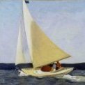
I thought you might like to see a few more pictures of the (slow) progress on my Sherbourne. The pictures were actually taken about a month ago, and my wife and I are now at our cottage, so work won't resume on her until the autumn.
I've now finished the shrouds apart from the ratlines, which I'm leaving off for access until later, and have in place some of the running rigging, including the burtons, top rope, boom topping lift, and throat and peak halliards for the mainsail. The latter is bent to the gaff and brailed into the mast:
-
Stockholm tar reacted to tkay11 in Sherbourne by Stockholm tar - Caldercraft - 1/64
Thanks, Kester. I think I should start putting smileys after light-hearted comments. I was only ribbing you about us poor learners, so don't take it to heart -- I think I understood your focus on Dirk! He's truly a great modeller, as you are, and we love learning from you both.
Tony
-
 Stockholm tar got a reaction from egkb in Sherbourne by Stockholm tar - Caldercraft - 1/64
Thanks guys, and you're right of course. My, perhaps rather badly-phrased, final sentence was really hinting at the workmanship Dirk has put into his version of the Sherbourne. Superb, I think you'll agree. Naturally, I'm only to happy for you to copy my ideas, such as the backstays, should they work for you.
Gregor,
I didn't actually notice the lead being visible in the deck box until afterwards, as I was intent on trying to get a good picture of the lieutenant. It does show to advantage though, I agree. By 'masthead', I take it you mean the lower masthead just below the doublings, where the upper parts of the shrouds are fitted, rather than the topgallant truck, at the very top? Either way, I can do probably that.
An inquiring mind is a good thing to have, rather than just accepting things for what they are. Luckily most of us have that, although I think it can be developed. We want to know not only how a thing works, but why it does so in a particular fashion. Regarding ship modelling, I always try to envisage how an item would work on the real ship, so that the operation of that item won't impede the operation of something else. I suppose having sailed might make this easier, but it can be done by anyone, and I'm sure reading on the subject helps.
-
 Stockholm tar got a reaction from Blue Ensign in Sherbourne by Stockholm tar - Caldercraft - 1/64
The kit is provided with two running backstays, one on each side but, in addition I decided to add two standing backstays, such as fitted to the Alert. This arrangement would appear to be the more likely – which is not really surprising, considering the large sail area of these cutters, and the mast support required. The backstays go next over the masthead after the shrouds, the standing ones nearest the mast first, followed by the running backstays further aft.
The standing backstays are fitted with deadeyes and lanyards, of a similar size to those for the shrouds, and I purchased four extra 5mm deadeyes for them. I had previously set eyebolts into the side of the hull for these backstays but now realised that they would be neither sufficient nor in the right position, and so removed them. The lower deadeye of the standing backstay sits on the edge of the cap rail, being bolted to a metal strengthening strap, which effectively transmits the pull of the shroud to the hull. On considering what might I might use for these I remembered the short brass strips left over in the kit, originally intended as handles (!) for the swivel guns and which I hadn’t used, but retained amongst my spare parts. However, they looked as though they just might make passable backstay straps. (Moral: never throw anything away you think you might find a use for!)
One end of each strip has a hole drilled in it, which I thought to use for pinning the strap to the side of the hull (conveniently through the holes which had previously held the eyebolts) whilst the other end comes to a point. After having rounded off the square corners at the ’hole’ end and slightly widened the hole itself (for some reason a new similar–sized pin wouldn’t fit!), I then turned the strip round and bent over the point, so that it formed a hooked shape. (My thinking was that this would hold firmly on the caprail, whilst leaving a small gap between it and the rail to pass a wire strap around the deadeye. The bent angle should also fit into the groove in the deadeye.) The finished strap was then laid aside, whilst I made a similar one for the backstay on other side. (Making up the pair together not only ensured that the same procedure was followed for both but the two will, hopefully, end up looking reasonably similar.)
I had originally thought to glue the strap and its deadeye to the hull as a single unit but, in doing this, I couldn’t be sure that the angle of the deadeye to the lie of the shroud would be correct. I therefore decided it was better to fix the strap first, then mount the deadeye to it. (I also only have one pair of hands and it would have been difficult, to say the least, to manage all of these procedures at the same time!) The way I eventually decided on to attach the strap, was to first cut the retaining bolt to the right length then, holding the end with small pliers, pass it through the hole in the strip, brush the other end with CA and push it into the hole in the hull – at the same time angling the strap to the seized shrouds on the mast, using a simple ruler. (A bit heath robinson, and it had of course had to be done quickly before the glue went off, but it did work after a fashion.)
A length of suitably-sized, flexible, wire was then passed under the turned over part of the strip on the rail and glued, leaving one end long, the other very short. The wire was to form the retaining strap around the deadeye. The wire was painted black, and the long end was then passed around the groove in the deadeye and under the bent over part of the strap. It was gently worked tight, with a pair of long-nosed pliers in one hand, the other aligning the deadeye in the direction of the lie of the shroud. The deadeye itself was left free within the wire strap, so that it could be correctly orientated. The long end of the wire was wound firmly three or four times around strap below the deadeye, anchoring the short end, being fixed with CA. A touch-up with black paint, and the job was done. (I may as well point out an error here, before the eagle-eyed amongst you do so, in that the deadeye is upside down! My fault entirely, being caught up in the intricacies of the work – but I am afraid the error will now have to remain.)
The whole process had been a little intricate so, rather than go straight to fitting the backstay strap on the other side, I first decided to rig the backstay and lanyard on the strap that I had just finished. The backstays, both standing and running, should be of a slightly smaller size than the shrouds, and I opted to use 0.7mm thread for them. The backstays on each side are of course single, the upper end being passed around the mast and seized to itself. Apart from that the same procedure was followed as previously for the shrouds. The distance between the two standing backstay deadeyes when rigged I decided to make about about half that of the main shrouds, in order that all of the deadeyes would be more of a uniform height. Having rove the backstay lanyard in the normal way, and as earlier described for the shrouds, I left the end long whilst I made and rigged the opposite side deadeye fittings and shroud, which were done in the same way. Both backstays were then finally tensioned, each lanyard being threaded between the shroud and the top of the deadeye with a needle, before being fastened off around the shroud.
Moving on to the straps for the running backstays, here again I decided that the eyebolts I had earlier placed for them would both be insufficient, and in the wrong position. I could now also see that it would be easier, with the mast and in situ, to judge where they should be positioned. Searching around for suitable material, I again remembered that left over from the swivel guns. This included the strips of metal originally intended for the gun supports, but which I didn’t think had looked quite right, and so had swopped for something else. The strips were rather long, having two creases in their length where they were supposed to be bent at right angles, giving two long sides and a middle shorter side, to form the support. I therefore cut one of the longer sides off, a process which left two holes, one in the remaining long side, and one in the short. The crease between them was slightly bent to accomodate the uneven side of the hull, and to which the long side could be glued. The hole in that side was used to pin the strap to the hull. The hole in the short end was used to attach the hooks of the running tackle, when the backstay was set up. With a pair of pliers I cut off the square corners at the short end, leaving the part with the hole proud, and which would protrude above the rail when positioned. I rounded off all the corners and then painted the finished straps black.
Using a length of thread from the masthead to align the shroud straps, I then fixed all four in position with CA. New holes then had to be drilled in the hull, through those in the lower part of the straps, for the pins. This operation had to be done very carefully, first using a drill size smaller than the hole and then enlarging it, so that the movement of the drill bit didn’t knock off the strap. (This actually did happen with one of them – which, naturally, promptly ’pinged’ off onto the floor, although I did eventually find it.) This operation took a little while, but the straps were all finally glued and pinned in position. It was then just a question of tidying up the upper wale and rail, and touching up the black paint on both.
The final job will be to attach the running backstays themselves and their associated tackle. However, this will have to wait until next time, as there was one small task to be done before that, and whilst I still had the access to do it. This was to position the first crew member on deck, the young lieutenant and commanding officer…
Next time: Setting up the running backstays.
-
 Stockholm tar got a reaction from Landlubber Mike in Sherbourne by Stockholm tar - Caldercraft - 1/64
The kit is provided with two running backstays, one on each side but, in addition I decided to add two standing backstays, such as fitted to the Alert. This arrangement would appear to be the more likely – which is not really surprising, considering the large sail area of these cutters, and the mast support required. The backstays go next over the masthead after the shrouds, the standing ones nearest the mast first, followed by the running backstays further aft.
The standing backstays are fitted with deadeyes and lanyards, of a similar size to those for the shrouds, and I purchased four extra 5mm deadeyes for them. I had previously set eyebolts into the side of the hull for these backstays but now realised that they would be neither sufficient nor in the right position, and so removed them. The lower deadeye of the standing backstay sits on the edge of the cap rail, being bolted to a metal strengthening strap, which effectively transmits the pull of the shroud to the hull. On considering what might I might use for these I remembered the short brass strips left over in the kit, originally intended as handles (!) for the swivel guns and which I hadn’t used, but retained amongst my spare parts. However, they looked as though they just might make passable backstay straps. (Moral: never throw anything away you think you might find a use for!)
One end of each strip has a hole drilled in it, which I thought to use for pinning the strap to the side of the hull (conveniently through the holes which had previously held the eyebolts) whilst the other end comes to a point. After having rounded off the square corners at the ’hole’ end and slightly widened the hole itself (for some reason a new similar–sized pin wouldn’t fit!), I then turned the strip round and bent over the point, so that it formed a hooked shape. (My thinking was that this would hold firmly on the caprail, whilst leaving a small gap between it and the rail to pass a wire strap around the deadeye. The bent angle should also fit into the groove in the deadeye.) The finished strap was then laid aside, whilst I made a similar one for the backstay on other side. (Making up the pair together not only ensured that the same procedure was followed for both but the two will, hopefully, end up looking reasonably similar.)
I had originally thought to glue the strap and its deadeye to the hull as a single unit but, in doing this, I couldn’t be sure that the angle of the deadeye to the lie of the shroud would be correct. I therefore decided it was better to fix the strap first, then mount the deadeye to it. (I also only have one pair of hands and it would have been difficult, to say the least, to manage all of these procedures at the same time!) The way I eventually decided on to attach the strap, was to first cut the retaining bolt to the right length then, holding the end with small pliers, pass it through the hole in the strip, brush the other end with CA and push it into the hole in the hull – at the same time angling the strap to the seized shrouds on the mast, using a simple ruler. (A bit heath robinson, and it had of course had to be done quickly before the glue went off, but it did work after a fashion.)
A length of suitably-sized, flexible, wire was then passed under the turned over part of the strip on the rail and glued, leaving one end long, the other very short. The wire was to form the retaining strap around the deadeye. The wire was painted black, and the long end was then passed around the groove in the deadeye and under the bent over part of the strap. It was gently worked tight, with a pair of long-nosed pliers in one hand, the other aligning the deadeye in the direction of the lie of the shroud. The deadeye itself was left free within the wire strap, so that it could be correctly orientated. The long end of the wire was wound firmly three or four times around strap below the deadeye, anchoring the short end, being fixed with CA. A touch-up with black paint, and the job was done. (I may as well point out an error here, before the eagle-eyed amongst you do so, in that the deadeye is upside down! My fault entirely, being caught up in the intricacies of the work – but I am afraid the error will now have to remain.)
The whole process had been a little intricate so, rather than go straight to fitting the backstay strap on the other side, I first decided to rig the backstay and lanyard on the strap that I had just finished. The backstays, both standing and running, should be of a slightly smaller size than the shrouds, and I opted to use 0.7mm thread for them. The backstays on each side are of course single, the upper end being passed around the mast and seized to itself. Apart from that the same procedure was followed as previously for the shrouds. The distance between the two standing backstay deadeyes when rigged I decided to make about about half that of the main shrouds, in order that all of the deadeyes would be more of a uniform height. Having rove the backstay lanyard in the normal way, and as earlier described for the shrouds, I left the end long whilst I made and rigged the opposite side deadeye fittings and shroud, which were done in the same way. Both backstays were then finally tensioned, each lanyard being threaded between the shroud and the top of the deadeye with a needle, before being fastened off around the shroud.
Moving on to the straps for the running backstays, here again I decided that the eyebolts I had earlier placed for them would both be insufficient, and in the wrong position. I could now also see that it would be easier, with the mast and in situ, to judge where they should be positioned. Searching around for suitable material, I again remembered that left over from the swivel guns. This included the strips of metal originally intended for the gun supports, but which I didn’t think had looked quite right, and so had swopped for something else. The strips were rather long, having two creases in their length where they were supposed to be bent at right angles, giving two long sides and a middle shorter side, to form the support. I therefore cut one of the longer sides off, a process which left two holes, one in the remaining long side, and one in the short. The crease between them was slightly bent to accomodate the uneven side of the hull, and to which the long side could be glued. The hole in that side was used to pin the strap to the hull. The hole in the short end was used to attach the hooks of the running tackle, when the backstay was set up. With a pair of pliers I cut off the square corners at the short end, leaving the part with the hole proud, and which would protrude above the rail when positioned. I rounded off all the corners and then painted the finished straps black.
Using a length of thread from the masthead to align the shroud straps, I then fixed all four in position with CA. New holes then had to be drilled in the hull, through those in the lower part of the straps, for the pins. This operation had to be done very carefully, first using a drill size smaller than the hole and then enlarging it, so that the movement of the drill bit didn’t knock off the strap. (This actually did happen with one of them – which, naturally, promptly ’pinged’ off onto the floor, although I did eventually find it.) This operation took a little while, but the straps were all finally glued and pinned in position. It was then just a question of tidying up the upper wale and rail, and touching up the black paint on both.
The final job will be to attach the running backstays themselves and their associated tackle. However, this will have to wait until next time, as there was one small task to be done before that, and whilst I still had the access to do it. This was to position the first crew member on deck, the young lieutenant and commanding officer…
Next time: Setting up the running backstays.
-
 Stockholm tar got a reaction from Jay 1 in Sherbourne by Stockholm tar - Caldercraft - 1/64
The kit is provided with two running backstays, one on each side but, in addition I decided to add two standing backstays, such as fitted to the Alert. This arrangement would appear to be the more likely – which is not really surprising, considering the large sail area of these cutters, and the mast support required. The backstays go next over the masthead after the shrouds, the standing ones nearest the mast first, followed by the running backstays further aft.
The standing backstays are fitted with deadeyes and lanyards, of a similar size to those for the shrouds, and I purchased four extra 5mm deadeyes for them. I had previously set eyebolts into the side of the hull for these backstays but now realised that they would be neither sufficient nor in the right position, and so removed them. The lower deadeye of the standing backstay sits on the edge of the cap rail, being bolted to a metal strengthening strap, which effectively transmits the pull of the shroud to the hull. On considering what might I might use for these I remembered the short brass strips left over in the kit, originally intended as handles (!) for the swivel guns and which I hadn’t used, but retained amongst my spare parts. However, they looked as though they just might make passable backstay straps. (Moral: never throw anything away you think you might find a use for!)
One end of each strip has a hole drilled in it, which I thought to use for pinning the strap to the side of the hull (conveniently through the holes which had previously held the eyebolts) whilst the other end comes to a point. After having rounded off the square corners at the ’hole’ end and slightly widened the hole itself (for some reason a new similar–sized pin wouldn’t fit!), I then turned the strip round and bent over the point, so that it formed a hooked shape. (My thinking was that this would hold firmly on the caprail, whilst leaving a small gap between it and the rail to pass a wire strap around the deadeye. The bent angle should also fit into the groove in the deadeye.) The finished strap was then laid aside, whilst I made a similar one for the backstay on other side. (Making up the pair together not only ensured that the same procedure was followed for both but the two will, hopefully, end up looking reasonably similar.)
I had originally thought to glue the strap and its deadeye to the hull as a single unit but, in doing this, I couldn’t be sure that the angle of the deadeye to the lie of the shroud would be correct. I therefore decided it was better to fix the strap first, then mount the deadeye to it. (I also only have one pair of hands and it would have been difficult, to say the least, to manage all of these procedures at the same time!) The way I eventually decided on to attach the strap, was to first cut the retaining bolt to the right length then, holding the end with small pliers, pass it through the hole in the strip, brush the other end with CA and push it into the hole in the hull – at the same time angling the strap to the seized shrouds on the mast, using a simple ruler. (A bit heath robinson, and it had of course had to be done quickly before the glue went off, but it did work after a fashion.)
A length of suitably-sized, flexible, wire was then passed under the turned over part of the strip on the rail and glued, leaving one end long, the other very short. The wire was to form the retaining strap around the deadeye. The wire was painted black, and the long end was then passed around the groove in the deadeye and under the bent over part of the strap. It was gently worked tight, with a pair of long-nosed pliers in one hand, the other aligning the deadeye in the direction of the lie of the shroud. The deadeye itself was left free within the wire strap, so that it could be correctly orientated. The long end of the wire was wound firmly three or four times around strap below the deadeye, anchoring the short end, being fixed with CA. A touch-up with black paint, and the job was done. (I may as well point out an error here, before the eagle-eyed amongst you do so, in that the deadeye is upside down! My fault entirely, being caught up in the intricacies of the work – but I am afraid the error will now have to remain.)
The whole process had been a little intricate so, rather than go straight to fitting the backstay strap on the other side, I first decided to rig the backstay and lanyard on the strap that I had just finished. The backstays, both standing and running, should be of a slightly smaller size than the shrouds, and I opted to use 0.7mm thread for them. The backstays on each side are of course single, the upper end being passed around the mast and seized to itself. Apart from that the same procedure was followed as previously for the shrouds. The distance between the two standing backstay deadeyes when rigged I decided to make about about half that of the main shrouds, in order that all of the deadeyes would be more of a uniform height. Having rove the backstay lanyard in the normal way, and as earlier described for the shrouds, I left the end long whilst I made and rigged the opposite side deadeye fittings and shroud, which were done in the same way. Both backstays were then finally tensioned, each lanyard being threaded between the shroud and the top of the deadeye with a needle, before being fastened off around the shroud.
Moving on to the straps for the running backstays, here again I decided that the eyebolts I had earlier placed for them would both be insufficient, and in the wrong position. I could now also see that it would be easier, with the mast and in situ, to judge where they should be positioned. Searching around for suitable material, I again remembered that left over from the swivel guns. This included the strips of metal originally intended for the gun supports, but which I didn’t think had looked quite right, and so had swopped for something else. The strips were rather long, having two creases in their length where they were supposed to be bent at right angles, giving two long sides and a middle shorter side, to form the support. I therefore cut one of the longer sides off, a process which left two holes, one in the remaining long side, and one in the short. The crease between them was slightly bent to accomodate the uneven side of the hull, and to which the long side could be glued. The hole in that side was used to pin the strap to the hull. The hole in the short end was used to attach the hooks of the running tackle, when the backstay was set up. With a pair of pliers I cut off the square corners at the short end, leaving the part with the hole proud, and which would protrude above the rail when positioned. I rounded off all the corners and then painted the finished straps black.
Using a length of thread from the masthead to align the shroud straps, I then fixed all four in position with CA. New holes then had to be drilled in the hull, through those in the lower part of the straps, for the pins. This operation had to be done very carefully, first using a drill size smaller than the hole and then enlarging it, so that the movement of the drill bit didn’t knock off the strap. (This actually did happen with one of them – which, naturally, promptly ’pinged’ off onto the floor, although I did eventually find it.) This operation took a little while, but the straps were all finally glued and pinned in position. It was then just a question of tidying up the upper wale and rail, and touching up the black paint on both.
The final job will be to attach the running backstays themselves and their associated tackle. However, this will have to wait until next time, as there was one small task to be done before that, and whilst I still had the access to do it. This was to position the first crew member on deck, the young lieutenant and commanding officer…
Next time: Setting up the running backstays.
-
 Stockholm tar got a reaction from Gabek in Correct hitch and advice on rigging a flag needed
Hi GabeK,
I see no-one has come back on this yet, so perhaps I can help.
To be accurate halliards which had any weight on them, such as for hoisting a gaff, usually had a tackle at the deck end to aid in the hoisting, which gave a mechanical advantage. This normally consisted of two double blocks with line rove between them, the end of the line being belayed to a cleat or pin, thus a knot wasn't needed. In fact it wasn't really desirable, since it could become very difficult to undo, if it tightened up under strain.
The end of the halliard proper was seized around the groove in the upper of the two blocks, whilst the lower block was fastened to the ringbolt in the deck. The line rove between the two was of smaller circumference than the halliard itself, one end being fastened at the lower end of the top block (usually through a small loop made in the seized halliard). It then ran through all the sheaves in both blocks, coming off of the top one, from where it ran down to the pin or cleat, where it was belayed.
As you say, there was a lot of rope left on deck when the gaff was hoisted. This was then neatly coiled, and hung from the same pin or cleat. On a model it is easier to make the coils separately, and attach them afterwards. You'll appreciate that the positions of the two blocks, relative to each other, will be different when the gaff is at full hoist than when it is lowered – them being closer together for the former position, and wider apart in the latter. You'd have to judge their approximate positions, on the model.
Regarding the flag, or ensign, at the end of the gaff. As far as I am aware, the toggle was the normal arrangement used on British ships, and I am not sure that other nations used this method. However, since the ship is American, they very likely followed British practice. The toggle was fastened close to the top of the flag, usually passing through a loop in the thin line that was stitched along the flag's hoist side, ie. that nearest the staff or halliards. The other end of the line, which protruded from the bottom for a little distance, had another loop in it. One end of the halliards also had a loop, through which the toggle on the flag was threaded, the other end passing through the loop in the end of the flag line, and normally made fast with a sheet bend. The ensign was now ready to hoist. All the other flags used would have had the same arrangement.
Incidentally, you might come to find that research is one of the more rewarding sides of ship modelling.
-
 Stockholm tar got a reaction from BANYAN in In need of shipyard workers or boats crewmembers
Well, ok – or at least I think so. I've just been having a look around my files and find that for some weird reason I seem to have kept some of it, but not all! However, all is not lost (well actually, some of it seems to be) as I have it printed out and can probably resurrect the missing parts again – given a few cups of coffee and infinite will power, deep into the night. You'll have to bear with me.
Actually, perhaps we should first ask Admin and the Mods what they think of the idea of me taking up screeds of the site capacity? If they agree then fair enough. On thinking more about this, perhaps there might be a dedicated thread for such offerings from members, if they feel so inclined, perhaps to include short stories, articles, or even poems about the sea, rather than put in on the General Discussion thread. Would this be a good suggestion?
In the meantime, I would be interested in the number of those who want to read my story again.
-
Stockholm tar reacted to Gabek in Correct hitch and advice on rigging a flag needed
I think I might post the completed model, Kester. But, I don't think I'll have a chance to work on it for a couple of weeks. A little behind in my paid work!
Regards,
Gabe
-
Stockholm tar reacted to Hollander-jan in HMC Sherbourne 1763 by Hollander-jan - Caldercraft - 1/64
The planking of the out site hul is finisht. Here are some pictures of the boat as he is now.
Jan
-
Stockholm tar got a reaction from egkb in HMC Sherbourne 1763 by tkay11 - FINISHED – Caldercraft – Scale 1:64 - A Novice’s Build
Tony,
Thank you for those kind words. I'm not sure she's that beautiful though, and I could list a few glaring errors, I've managed to hide - but then as you said, we are our own worst critics! However, you might have a point, re. the focus.
Well, I suppose there are things to be said for keeping things simple, and I've learnt to live with it (or perhaps that should be without it), but just occasionally I think it would be nice to have all this machinery. I do however, have a scroll saw at the summer cottage which comes in handy on occasion...
Btw, I hope to have an update to my log soon which, I have a feeling, is somewhat overdue...
-
 Stockholm tar got a reaction from Gregor in HMC Sherbourne 1763 by tkay11 - FINISHED – Caldercraft – Scale 1:64 - A Novice’s Build
Tony,
Thank you for those kind words. I'm not sure she's that beautiful though, and I could list a few glaring errors, I've managed to hide - but then as you said, we are our own worst critics! However, you might have a point, re. the focus.
Well, I suppose there are things to be said for keeping things simple, and I've learnt to live with it (or perhaps that should be without it), but just occasionally I think it would be nice to have all this machinery. I do however, have a scroll saw at the summer cottage which comes in handy on occasion...
Btw, I hope to have an update to my log soon which, I have a feeling, is somewhat overdue...
-
Stockholm tar got a reaction from egkb in HMC Sherbourne 1763 by tkay11 - FINISHED – Caldercraft – Scale 1:64 - A Novice’s Build
Tony,
Good post on those upgrades, and I especially liked your technique for sanding the base of the gratings – so simple, and sets one to thinking now why didn't I think of that? That's why MSW is so good, someone is bound to think of new ways of doing things.
I have to say that I am rather envious of yours, and others, workshops. Not having a dedicated area in our flat, I use the worktop in the kitchen for my modelling, which means that I have to clear it all away after each session. Naturally using anything other than simple tools, like a Dremel, is out as it would create too much dust, and would certainly take up too much space – plus my wife might have something to say! It's nice though to see what others are doing.
I'd certainly agree with you, that thinking around the problems that crop up keeps the old brain cells functioning!
-
Stockholm tar reacted to tkay11 in HMC Sherbourne 1763 by tkay11 - FINISHED – Caldercraft – Scale 1:64 - A Novice’s Build
Thanks, Kester. Certainly no need to be envious when your builds are so beautiful. It may well be that your focus on a simple modelling space gives you a similar focus on the perfection of your builds.
You're quite right about keeping tools simple. Underhill was a great champion of the card table and basic tools. I too had hoped I would avoid buying the nice new electrical aids (saw, sander, wood lathe) but I succumbed to the temptation as I kept being frustrated by my inability to use simple tools. I am also very aware of the fact that other modellers have been doing this for much longer than I have (or are people who've worked with tools and wood throughout their lives), and so have had time to build up their skills. In my case, now that I am about to be 67, and I haven't had such a lifetime of experience, I reckon the time available to build up those skills is limited -- even though I would like to develop those same skills. So it's all a bit of a balance.
Two examples of my failure:
(1) keeping the depth of the hollows in the shot racks constant (with my modified drill stand the depths are now constant). I can envisage being able to do it otherwise, but it was so much simpler to use a drill stand.
(2) sanding exactly parallel to a surface. I know I could build jigs to achieve flat sanding, but again it was in the end more convenient to buy a sander.
All the same, I'm glad you liked the biscuit tin -- even my wife approved! These simple solutions are definitely the ones that are the most enjoyable. The machinery is just luxury -- although it is also fun learning the skills involved in operating it properly.
Tony
-
Stockholm tar reacted to tkay11 in HMC Sherbourne 1763 by tkay11 - FINISHED – Caldercraft – Scale 1:64 - A Novice’s Build
I had started on the channels and deadeyes last month, but was distracted by the continuing discussions about mills. I was sure that there must be some way of modifying my drill stand to act as a mill, and sure enough, after a lot of web searching, I found a railway hobbyist who had done exactly that with his Proxxon drill stand. He was kind enough to share the details and provide a sketch.
So with the sketch in hand, I adapted my drill stand as you can see if you look at my positng on the forum about this (see ‘How to modify Proxxon MB 140 drill stand to act as mill’ at http://modelshipworld.com/index.php?/topic/4539-how-to-modify-proxxon-mb-140-drill-stand-to-act-as-mill/?p=130660).
This in turn led me to buy an x-y table for the drill stand as well.
With all this thinking about better precision, a glance at the deck and looking at all the wonderful work on this forum showed me I could do a lot better with the guns, the shot racks, and the hatches. So why leave learning the skills to do better until later? Answer: do them again, but better if possible.
Replacing the shot racks
So the first thing to do was to remove all the shot racks. Unfortunately I had used epoxy adhesive to stick them to the walls. Despite much soaking in Isopropanol, they refused to give way, so I had to attack them with chisel blades. They came off, but it was clear I’d have to replace them as small patches of wood were also torn off the walls at the same time.
That done, I cut some new strips of wood from some pear pen blanks using my Proxxon FET saw (with which I am at last really comfortable and pleased with the precision it can offer) and loaded them on to a jig that would hold them on the x-y table.
That allowed me to mill a nice series of three hollows at a time spaced by 0.5mm, leaving gaps between each three hollows to file out as individual shot racks.
I finished them off with a face plate, and painted them. I again used the x-y table to drill holes for the gun bolts that would go into them, and then with some of the salvaged bolts and rings from the previous racks, installed the bolts. The racks were then set aside until I had finished more of the other deck furnishings.
Replacing the hatches – (1) the Gratings
I had for some time been thinking about learning how to do gratings for myself – I had read a lot about the standard technique of using a circular saw, but had been somewhat mystified as to how to get a groove exactly at the right spacing from the saw blade.
Of course, the answer was obvious the moment I decided to put blade to plywood panel. The way to achieve a perfect spacing was simply to start by cutting the slot in the panel by clamping the panel to the table top and having one edge of the panel firmly against the fence. Then, once the slot was cut, the panel was turned over and a spacer of the correct width was inserted between the panel and the fence.
I had decided that I’d go for 0.8mm strips for the gratings with a corresponding hole size of 0.8mm in order to achieve a scale size of 2” for the gratings (it’s a 1:64 model). The kit gratings are about 1mm and they just looked a bit too big to my eye.
Luckily I have a 0.8mm saw blade with no kerf, and after several attempts using a 0.8mm gauge from an old set of feeler gauges I had, I managed to cut 0.8mm strips that I could use in the slot.
One little hint that others might find useful is to set the depth of the cut using feeler gauges until you can just feel the edge of the saw over the edge of the gauge as you raise it through the slot.
I had especially enjoyed Dafi’s account of his trials making gratings (at http://modelshipworld.com/index.php?/topic/1449-making-gratings/?p=29923), and I went through similar set-backs. My main problem was making sure the grooves for the gratings were parallel. Given the grooves were 0.8mm, and that I was pushing the block of wood by hand over the blade, minute variations in the pressure I was using resulted in (1) increasing deviation from parallel as I went further into the block, and (2) a very small variation in the spacing between cuts. I found that a deviation of 0.01mm would translate into blocks that would have slightly different spacing, and that this would result in gratings that would only interlock for about 7 or 8 bars.
To overcome the problem of variance from parallel cuts, I used a block of wood that covered both sides of the spacing bar as well as the blade. This was then pushed through by the cross-slide/ angle stop. I never quite managed to make grooves that were perfectly spaced for more than a couple of centimetres, but I found that that did not matter – the only grating that was large was the main grating and I found all I had to do was make up the central section as a cross hatch and then simply add ordinary strips of the right depth to the remaining outer grating grooves.
Another recent purchase was a Proxxon sander. This I really find valuable. It allowed me to finish off the coamings around the gratings with ease.
Curving the gratings
I have seen that others bend their gratings using heat. I wasn’t quite sure how I’d do that and then put coamings round them. So I used an old biscuit tin first to shape the underside of the gratings, and then to shape a mirror mould so that I could curve the top of the gratings.
Replacing the hatches – (2) Main companionway
It has been said that the Alert’s deck plan would not work for the Sherbourne because the Sherbourne is smaller and using the hatches from the Alert would make the deck far too cluttered. That’s probably true, but I liked the look of my old companionway, so I just re-did it using pear wood from the pen blanks I had bought off eBay. It’s a bit better now, but not enormously so.
Replacing the hatches – (3) The Captain’s companionway
Much more interesting was the aftmost companionway. Others have preferred a tall structure, but I thought I’d stick with the Alert’s glass-covered one – mostly because I wanted to try my hand at using Perspex and embedding mullions in it. I didn’t like the rather tatty look of the one I first made, especially as I had CA glue marks on the plastic sheet I had used for the window panes.
At first I tried using my modified drill stand to mill the grooves for the mullions in the Perspex. However, it soon became clear that with my drill at its very high speed the melting Perspex on the mill bit made the process unworkable. Even worse, I snapped my 0.8mm mill bit when trying to remove it from a solidified ball of Perspex.
However, it struck me that I could use the skills I had learnt for the gratings. After a bit of experimentation, using a 0.6mm blade and making the necessary 0.6mm strip for the jig, it was relatively easy to slice grooves to a depth of 1mm in a 2mm Perspex block.
With another bit of luck, I remembered that some 0.5mm strips of cherry wood that I had previously ordered were in fact 0.6mm thickness – so they made perfect mullions for the grooves in the Perspex.
I first cut longitudinal grooves in the Perspex, then fitted the strips of cherry wood into those grooves (using small amounts of CA glue along the bases). These were sanded down to 1mm from the surface of the Perspex.
The block was then rotated and the horizontal cuts were made with the saw using the same jig – though this time the depth of the cut was adjusted to allow for the extra depth made by the inserted longitudinal strips of cherry.
With this done, the horizontal strips of cherry could then be inserted into the horizontal grooves, and the whole was then sanded down with the sander.
The final touch was to mill a couple of slots for the hinges and to insert two 2.5mm lengths of 0.5mm brass wire into the slots.
Watch out with the vacuum cleaner!
I had rigged up a vacuum cleaner nozzle over the sanding machine as I found that was more successful at removing wood dust than the outlet provided for the sander.
Unfortunately, the double sided tape I had been using to fix the companionway cover to a block of wood (to make the sanding more accurate and less dangerous) became worn and, as I was nearing the last bit of sanding on this rather precious piece, the vacuum cleaner simply sucked up the piece!
So I spent a dusty 15 minutes taking the bag out of the vacuum cleaner and sifting through the dust until I found my precious tiny piece again.
Still to come:
Cannon Channels and deadeyes
Tony
-
Stockholm tar reacted to Hollander-jan in HMC Sherbourne 1763 by Hollander-jan - Caldercraft - 1/64
Thanks for this very well done answer Kester. I have thougt about planking around the ports in some way and will do this in the futher.
For now I am busy and very careful opening the ports and is satisfactory.
The trouble is that there is not enougf patients in me but it is comming around.
About the ports and the places this is due to an erlier mistake. I have checked but all wil go as far as deck is concerned.
I see this as a learning ship and stil having fun to work on it.
Jan
-
 Stockholm tar got a reaction from tkay11 in HMC Sherbourne 1763 by Hollander-jan - Caldercraft - 1/64
Jan,
I think I would approach this from the other side, as it were. From the inside of the bulwark you can actually see the position of the gunport, and sweep ports, on the opposite side – something rather difficult to gauge any other way! This will give you the exact size to go for.
Next, I think I would try drilling the holes for each port across the model, from inboard – one in each corner and one in the middle. Start by pricking where the holes should go (so that the bit doesn't 'wander'). If you're very careful you might use be able to use a Dremel, with a small size bit. If you don't think you can manage that, try doing it by hand. In awkward places I have often held the bit by hand (pressing with the thumb) against the wood and twisting it. This will take a little while, but it does work.
When the holes are made, and so marking the area to be removed, from the outboard side you can then carefully cut straight between them with a sharp knife, and then tidy each port up with a file. I hope this helps.
Something to remember, perhaps, for your next model. It might be better, and easier, to plank around the gunports (how it is done on the real ship) rather than plank over them, and cut them out afterwards. As you become more proficient in model building, you'll probably realise the instructions are there only as a guide – and that there are other ways to achieve a goal!
Btw, I don't fully understand why you moved some of the gunports, as I think this could cause problems later, with other deck fittings.
-
Stockholm tar got a reaction from Landlubber Mike in Victory by mikec - FINISHED - Mamoli
Mike,
In addition to what has already been said:
I don't believe the Victory would have worn the red-white-blue Union pennant at the main truck, but rather as BE said, the plain white. The Union pennant was normally reserved for ships on detached service, i.e. they were on their own, and worn with a red ensign – the senior flag in the then squadronal system. (Unfortunately many kit firms supply this pennant for the Victory, which I think is incorrect.)
The small piece of wood at the top of flags is called the 'toggle' and was slipped into an eyesplice in one end of the halliard. The bottom of the flag had a short length of line attached, with an eyesplice in its end. The other end of the halliard was bent to it with a sheetbend. The mast trucks by the way were fitted with two sets of halliards, one to larboard, the other to starboard. So far as I know, the halliards would actually have come down to the deck, and belayed at the after end of the shrouds, for each mast.
I note you have the white ensign hoisted at the mizzen peak, but that you also appear to have the ensign staff shipped. I'm not sure the latter would have been fitted at the same time, being normally used for when the ship was in harbour or at anchor. In fact I would have used the staff, seeing that you have the jack on the bowsprit.
Btw, a very fine model, I'm sure the museum will be proud to exhibit it.
-
Stockholm tar got a reaction from Jay 1 in HMC Sherbourne 1763 by Gregor – FINISHED - Caldercraft – Scale 1:64 - first build
Gregor,
Very good work on both the jeer bitts and the bell, they look most authentic!
The anchor cable going around the crosspiece on the bitts probably wouldn't have mattered much, as it would have been hauled in by hand in any case, and veered on deck when letting go. I'm not too sure about the belaying pins though, as I would have thought them rather low to belay ropes around, and to accomodate the coils without getting them tangled.
Since I believe the bitts would have been used for various hauling jobs, I have an idea that rope stoppers would have been employed. These were short lengths of line, one end of which was probably fastened to a ringbolt in the deck near the bitts, the other end being temporarily bent to whatever line happened to be attached to the bitts at the time, and when it was at full hoist. This was then held fast be a crew member, taking the strain, whilst the line was quickly transferred from the bitts to its own belaying pin or cleat, which would have been in the vicinity or on the mast.
I have no definite proof of this and have not read anything about how the bitts were operated, but stoppers were frequently used for various jobs like this. They are also used on modern vessels. The stopper works partly by friction, it normally being half hitched around the halliard or whatever, the end then being wound around it against the lay. Apologies for bringing this up, but I thought it worth mentioning.
Gregor, a valiant effort in getting the mechanism to work! I have previously wondered about the length of the handles specified. Mine are short too, but I did wonder if their were possible extensions to lengthen them, when in operation. As they are, it seems as though only two people could be accommodated, one on each handle – which doesn't really seem sufficient manpower. My overactive brain again (!), but does anyone have any thoughts on this?
-
Stockholm tar reacted to Gregor in HMC Sherbourne 1763 by Gregor – FINISHED - Caldercraft – Scale 1:64 - first build
It’s the season. Its pure kitsch, but I had to add it now. Feel free to hum or whistle an appropriate tune according to your personal taste or custom.
The brass bell was a gift. I used two 0.3 mm brass eyelets and a small piece of copper to mount it.
Merry Christmas and a happy New Year to you all. Thank you for all the encouragement and wisdom. I’m very much looking forward to seeing you again in 2014!
Gregor
-
Stockholm tar reacted to Gregor in HMC Sherbourne 1763 by Gregor – FINISHED - Caldercraft – Scale 1:64 - first build
With Tony’s much appreciated help I built my version of jeer bitts with a windlass.
A friend challenged me to make the windlass working – well, it turns around till the soldered handles break (almost instantly, to be fixed with superglue). The pawls don’t stop anything, but were fun to make.
I found another way to make the pawl drums: the brute force method, with pliers and a hammer.
Mounting the assembled jeer bitts, I foresee some headaches in the far future: Belaying will be difficult in the confined space between the main hatch and the cross piece.
The anchor cables will have to go around the jeer bitts, but this can be seen in contemporary models (the Hawke, in Goodwin’s Alert book).
All the best,
Gregor
-
Stockholm tar got a reaction from egkb in HMC Sherbourne 1763 by Hollander-jan - Caldercraft - 1/64
Hi Jan,
I've just caught up with your log. Good work with your clinker planking, and I think you've found it's not so difficult. Believe me, I felt the same before doing mine, and as I think you've found, it is manageable. If I have a small criticism, it is that I think you might have overlapped the planks perhaps a little more, and you have to keep an eye on the tapering. All in all though very well done.
I think you've also learnt that it's better to progress at a slower pace, trying to make each part as best you can, rather than hurrying to get to a perhaps more enjoyable part of the build. Trying I know, but you'll end up with a better model as a result. Tony also hit the nail on the head when he said that we are our own worst critics!
I see you've made up one of the guns. Good idea for checking those gunport heights – I wish I had thought of doing that, since my larboard bulwark was a little too low at the stern. It isn't noticeable, but let's just say the two after guns needed some serious modification to fit – and even then they just cleared the upper edge of the port! You might want to think about shortening the trunnions, they're the metal pins the gun rests on on the carriage, as they shouldn't overlap the carriage sides. A small file should do it.
Look forward to seeing what's next.