.jpeg.882f0a147f14858c9e673da7e13d8ebe.jpeg)
RossR
-
Posts
532 -
Joined
-
Last visited


-
 RossR reacted to a post in a topic:
HM cutter Sherbourne by Maid of the Mist - Vanguard Models - 1:64
RossR reacted to a post in a topic:
HM cutter Sherbourne by Maid of the Mist - Vanguard Models - 1:64
-
RossR reacted to a post in a topic:
HMS Harpy 1796 by dunnock - Vanguard Models - 1:64
-
RossR reacted to a post in a topic:
HMS Victory 1805 by kiwiron - Caldercraft - 1:72
-
CODY reacted to a post in a topic:
HMS Indefatigable 1794 by Mowzer - Vanguard Models - 1:64
-
RossR reacted to a post in a topic:
HMS Victory 1805 by kiwiron - Caldercraft - 1:72
-
RossR reacted to a post in a topic:
Duchess of Kingston 1798 by Glenn-UK - Vanguard Models - 1:64 - Commission Build
-
RossR reacted to a post in a topic:
US Frigate Essex by Dave Wells - Model Shipways - 5:64
-
RossR reacted to a post in a topic:
HMS Beagle by Maid of the Mist - FINISHED - OcCre - 1:60
-
RossR reacted to a post in a topic:
Polaris by Meekes - OcCre - 1:50 - First Build
-
vvvjames reacted to a post in a topic:
USF Essex 1799 by RossR - Model Shipways - 1:76
-
RossR reacted to a post in a topic:
US Brig Syren by Argaen Lok (aka Scott Larkins) - Model Shipways - Scale 1:64
-
RossR reacted to a post in a topic:
US Brig Syren by Argaen Lok (aka Scott Larkins) - Model Shipways - Scale 1:64
-
schooner reacted to a post in a topic:
USF Essex 1799 by RossR - Model Shipways - 1:76
-
Freebird reacted to a post in a topic:
USF Essex 1799 by RossR - Model Shipways - 1:76
-
PaddyO reacted to a post in a topic:
USF Essex 1799 by RossR - Model Shipways - 1:76
-
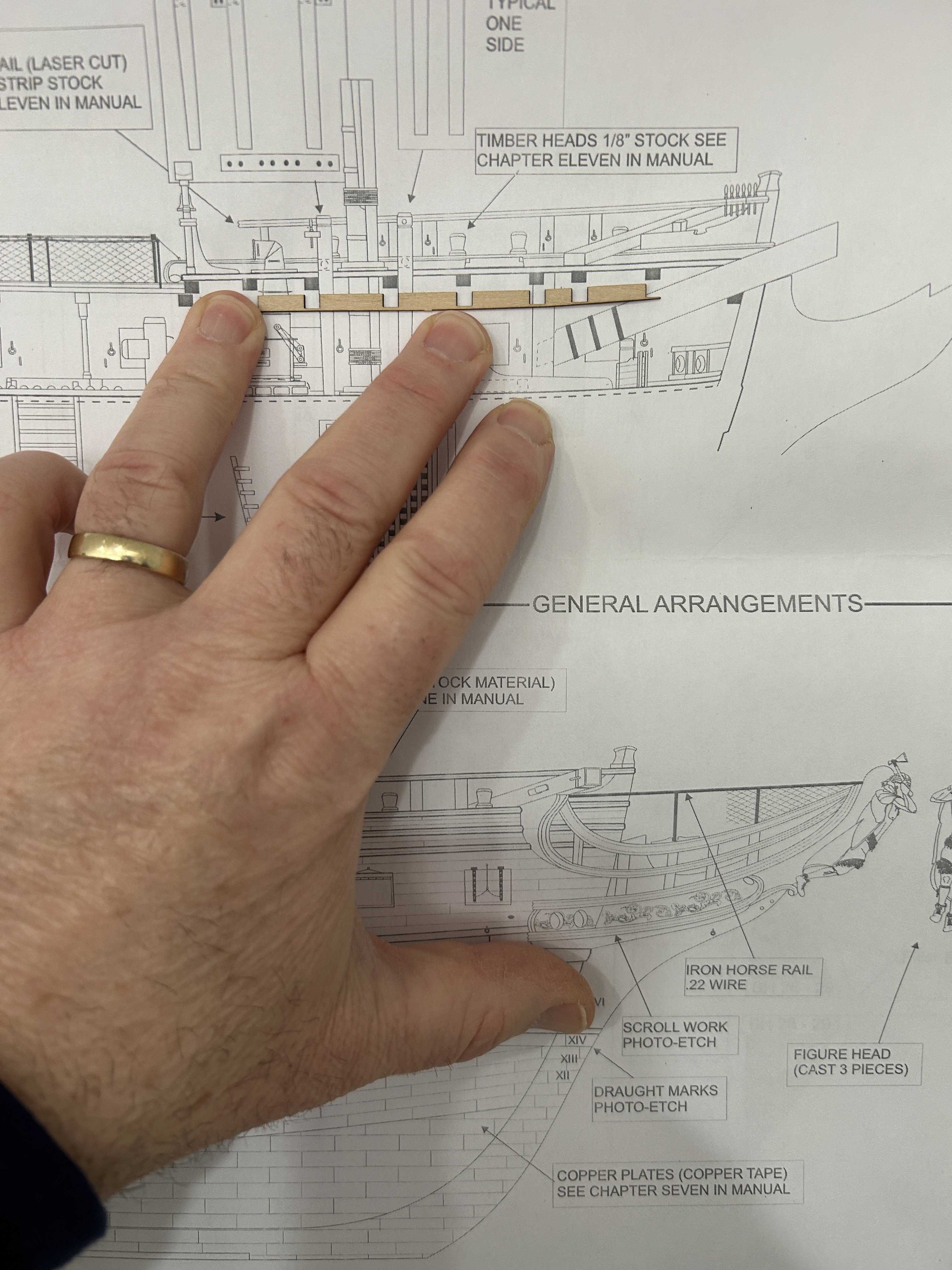
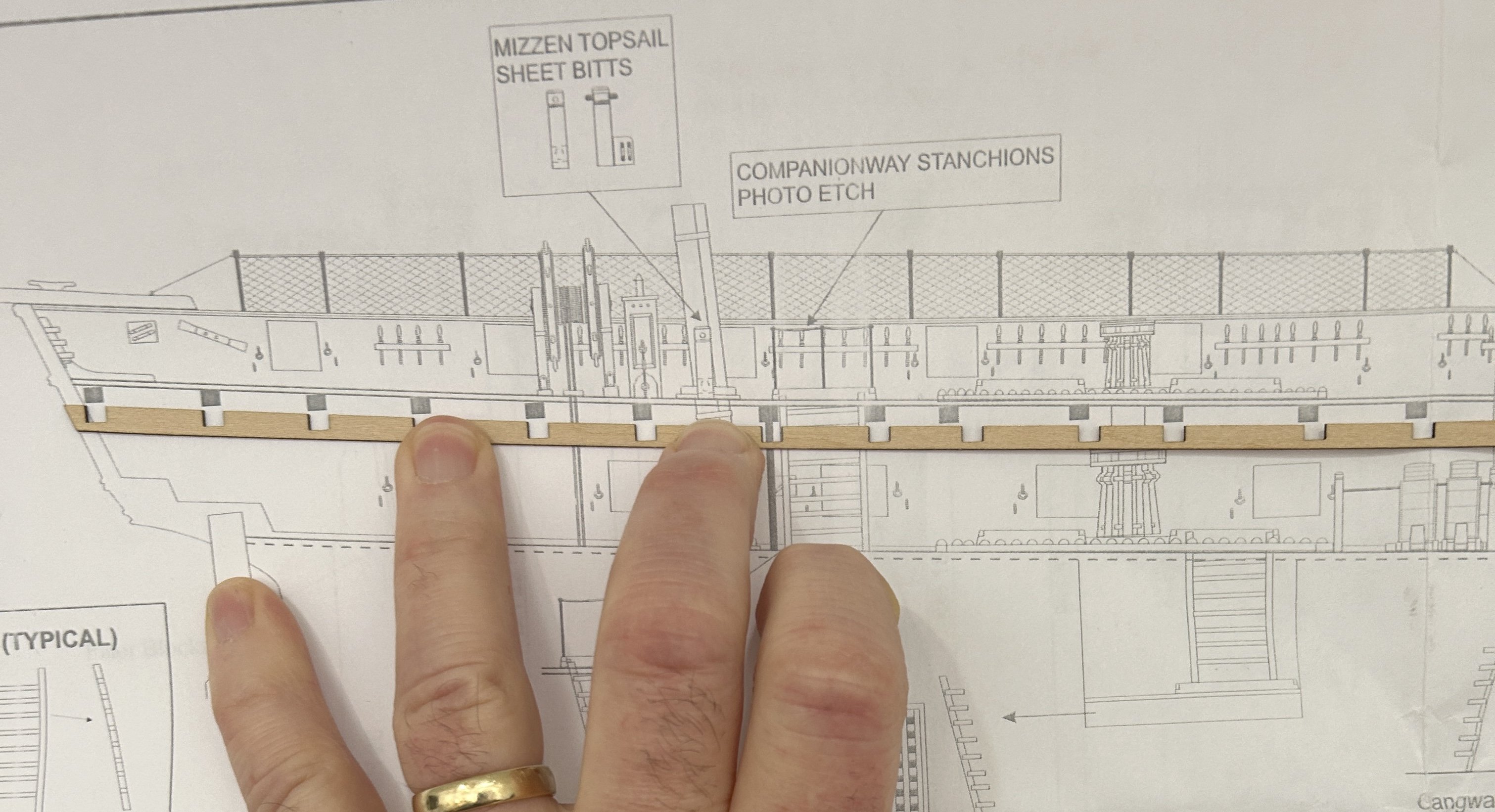
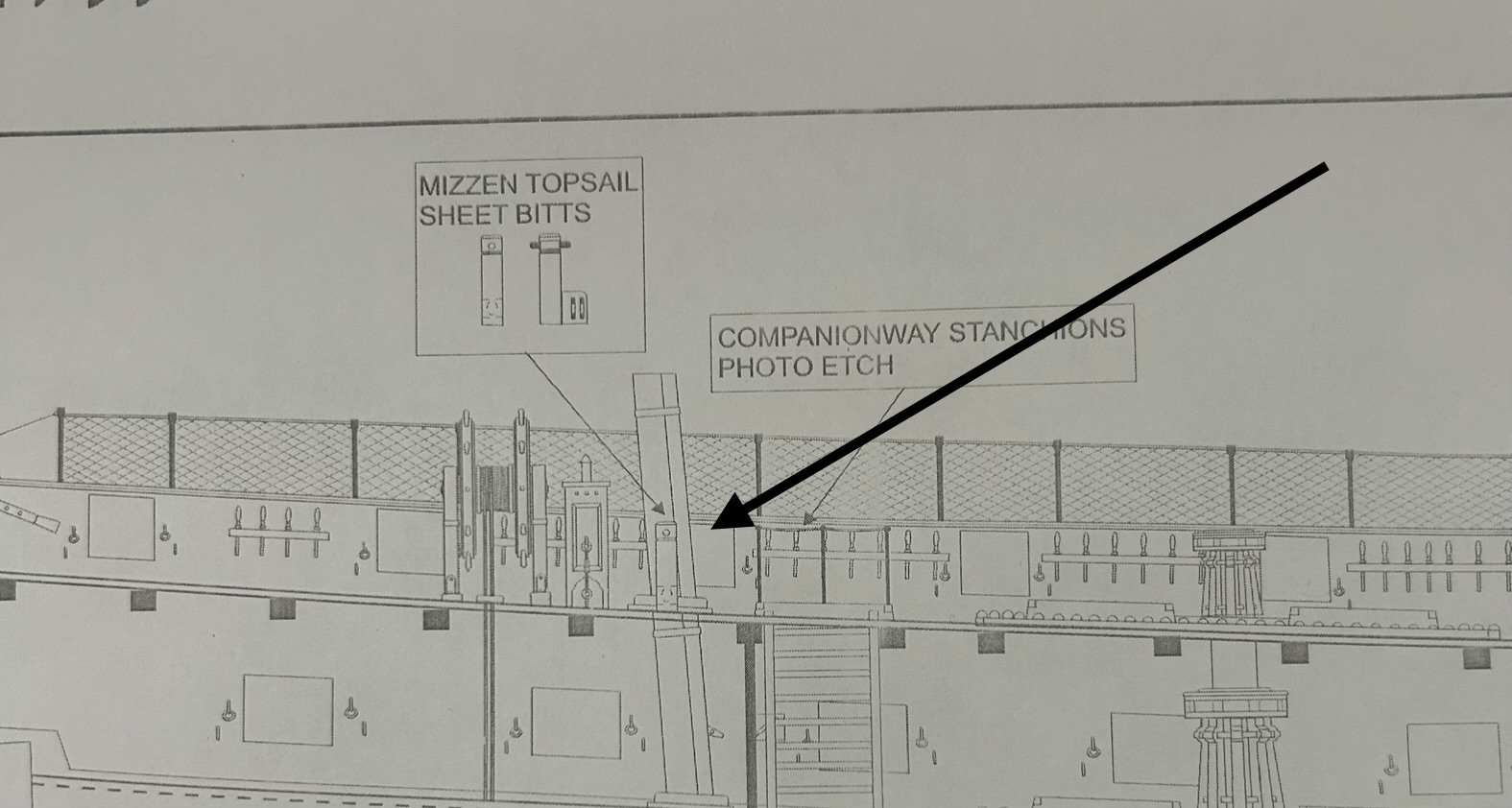
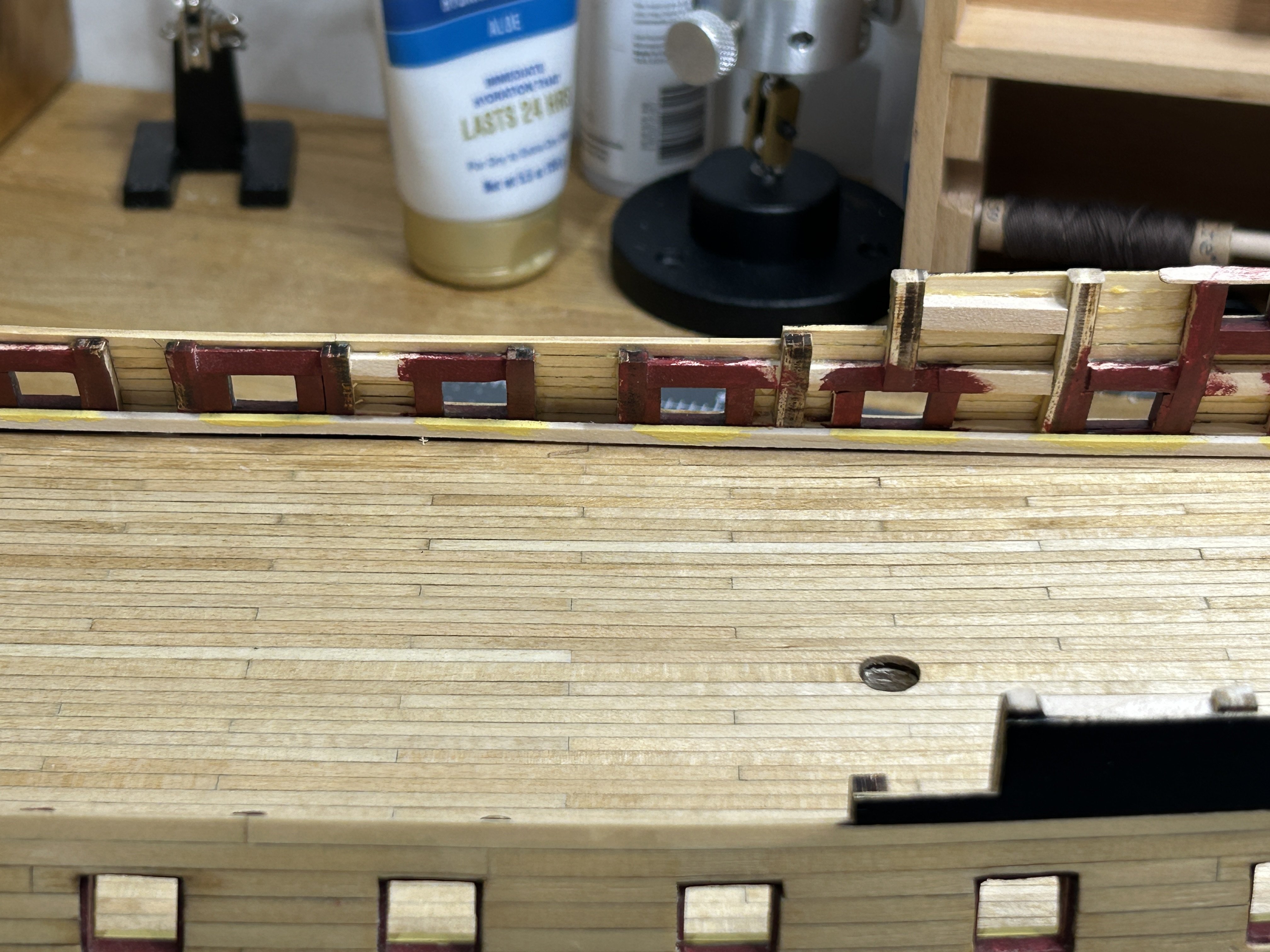
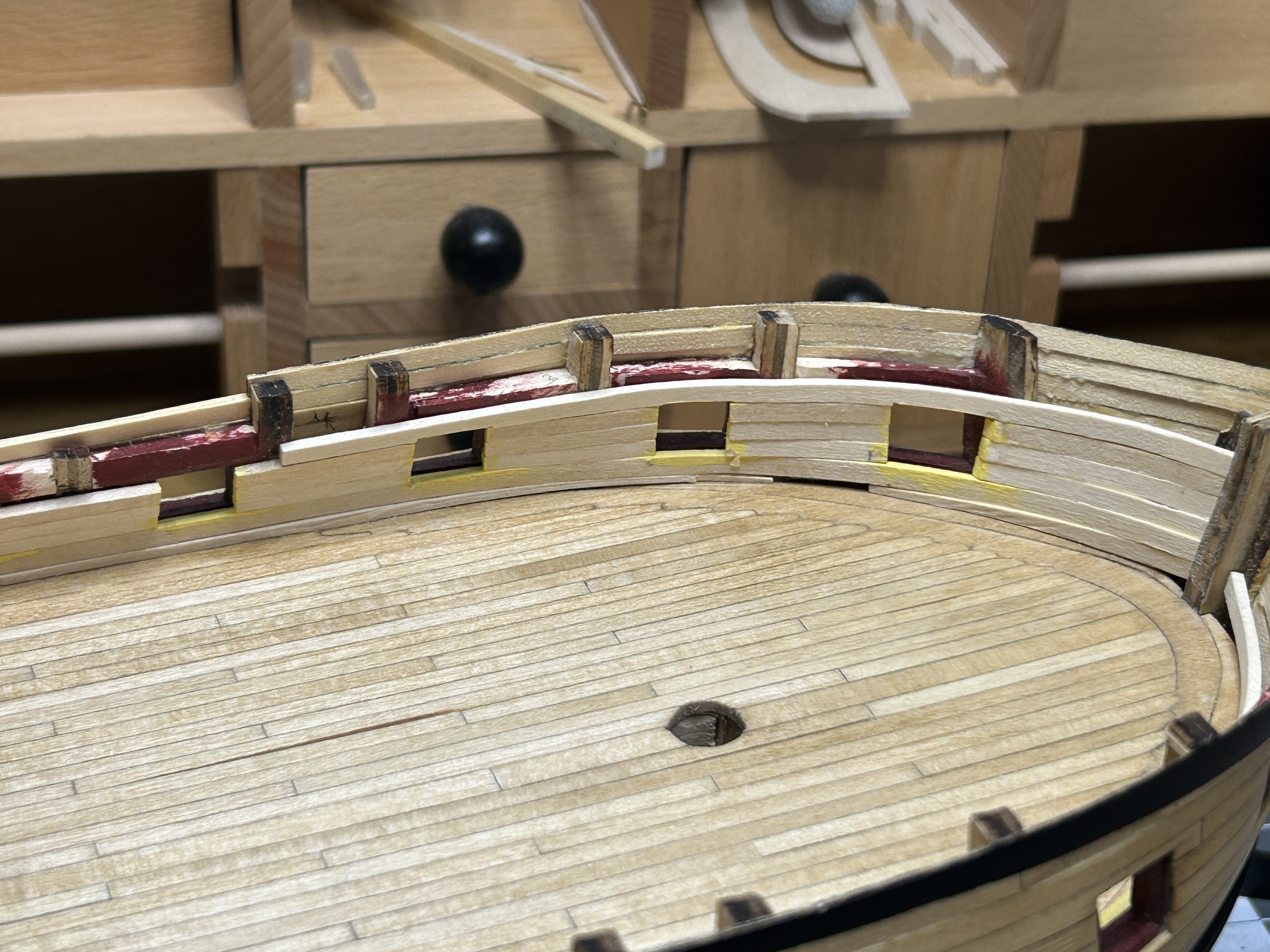
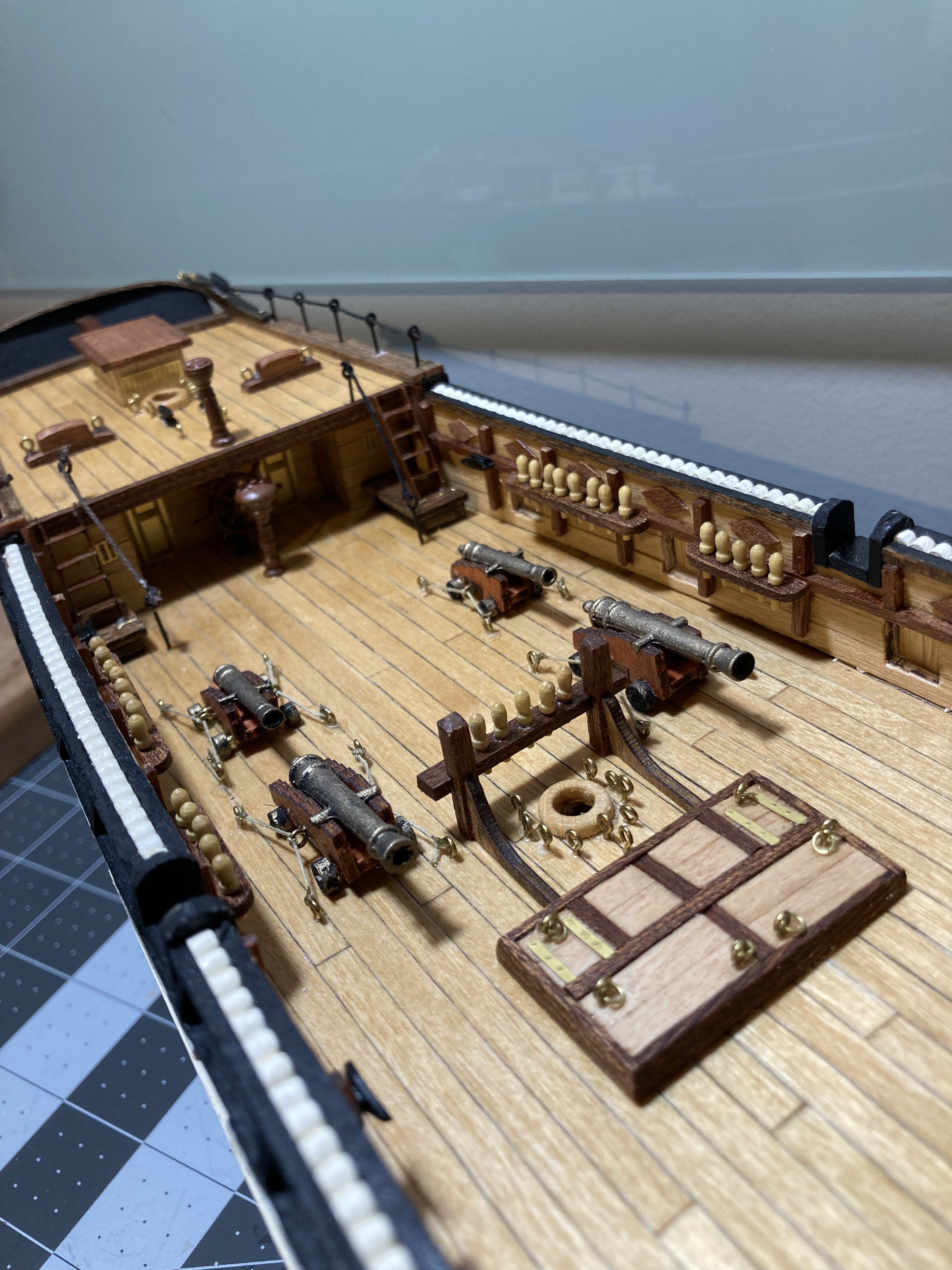
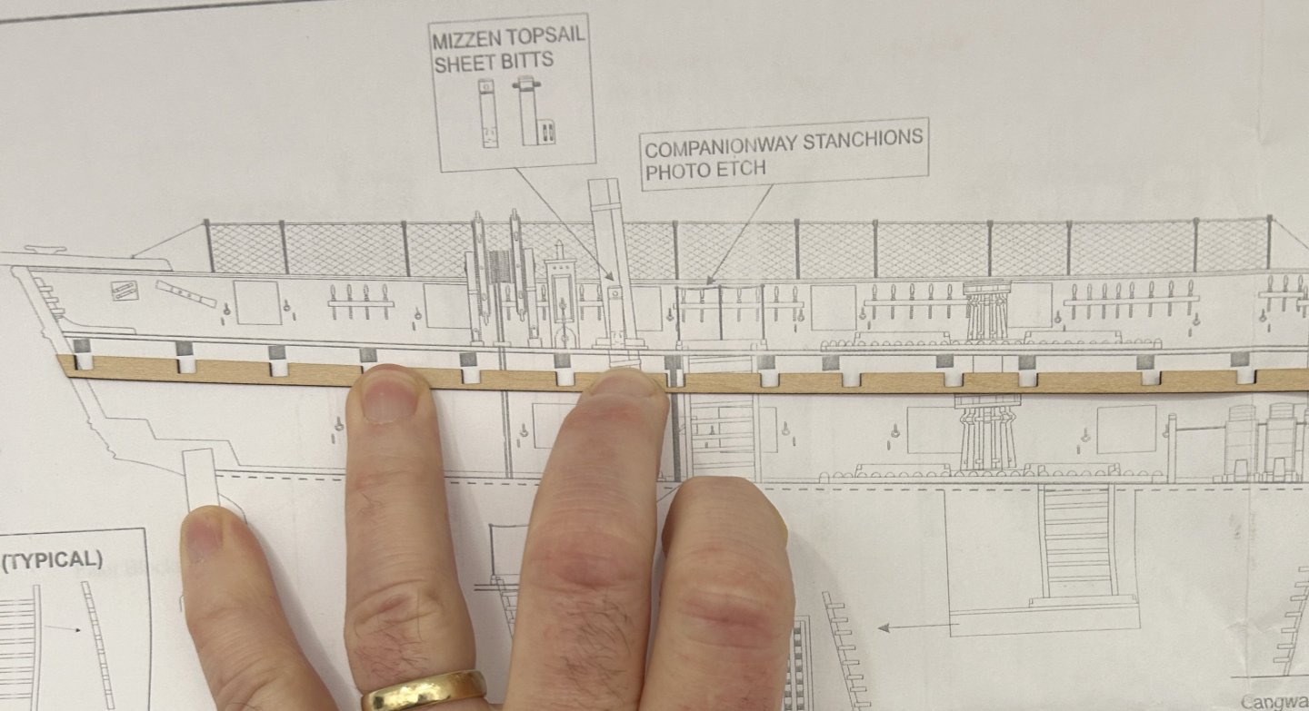
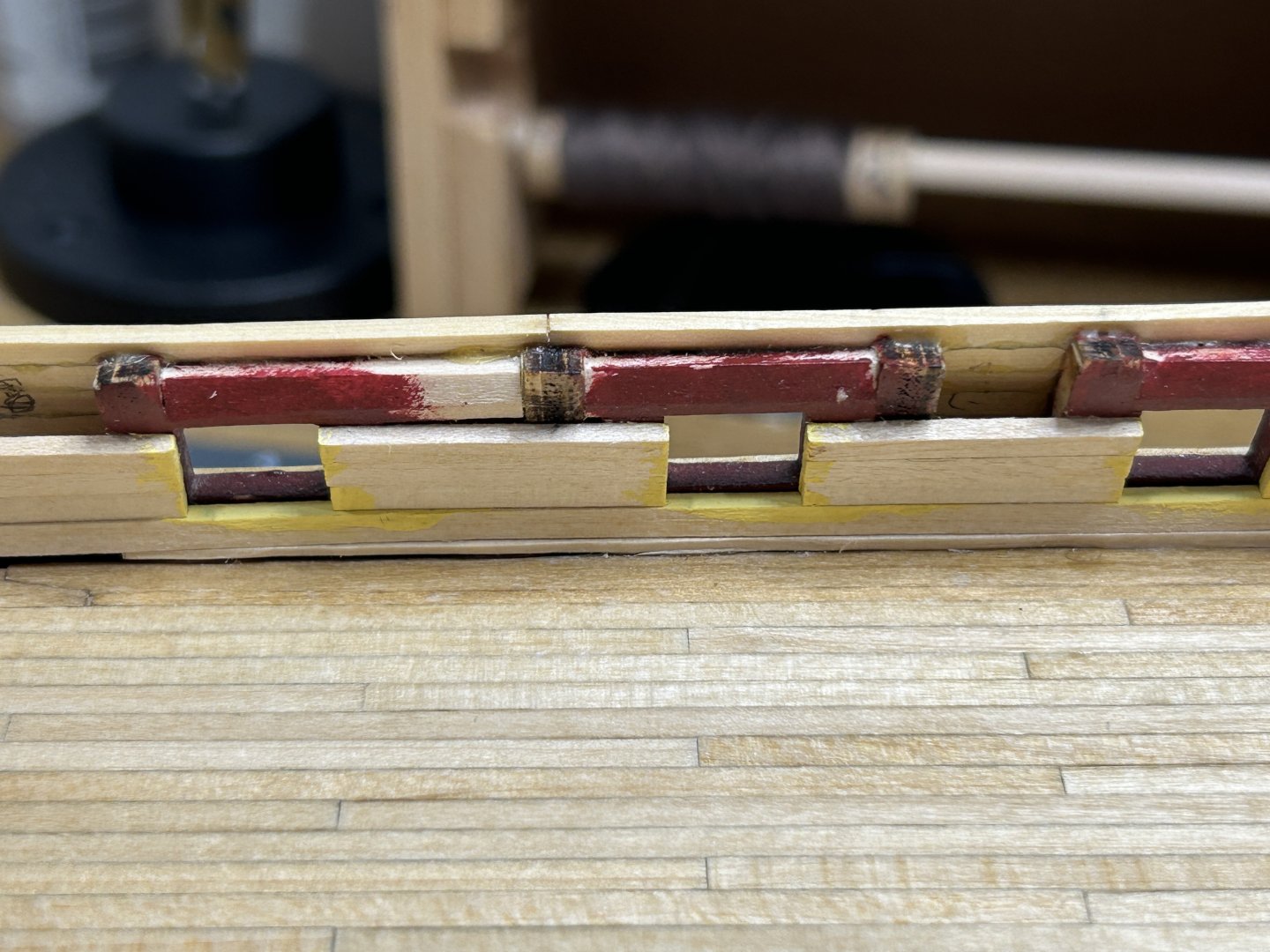
.thumb.jpeg.ffac2f8a24d212961a83eab4efb06a6c.jpeg) I have the interior planking installed and are working on painting. I have also started thinking about the placement of the beams. The kit uses strips of 1/32 inch thick beam pockets that are glued to the bulwarks for the beams to rest on. 1/32 of an inch is really thin. I am concerned about their ability to support the beams as the deck is installed and the margin plank is cut into to joggle the planks. I am also concerned that with a slight inward flare to the bulwarks it will be really hard the fit the beams without making them slightly undersized. This would result in not being long enough to rest on the 1/32 pocket. I can take steps to add additional material to overcome this problem. I still need to install them in the proper place. The plans show where the beams are placed on a completed model, but most of the features that can be used for reference from the plans are not installed yet. you can see one of the beams is placed in a location on the plans different form the beam pocket. My biggest issue is the placement of the mizzen mast. The actual placement of the mast on the model is determined by a hole precut in the false deck. Unfortunately that hole is about 1/2 - 3/4 further aft than the plans show. This will create a conflict with the placement of one of the beams. I will need to figure out how to adjust for this. I was attracted to this model due to the detail of the features on the gun deck and top deck. The instructions for these features are complete and extensive. Unfortunately for the placement of the beam pockets the author gave us 1 short paragraph with no real instruction on where to place then.
I have the interior planking installed and are working on painting. I have also started thinking about the placement of the beams. The kit uses strips of 1/32 inch thick beam pockets that are glued to the bulwarks for the beams to rest on. 1/32 of an inch is really thin. I am concerned about their ability to support the beams as the deck is installed and the margin plank is cut into to joggle the planks. I am also concerned that with a slight inward flare to the bulwarks it will be really hard the fit the beams without making them slightly undersized. This would result in not being long enough to rest on the 1/32 pocket. I can take steps to add additional material to overcome this problem. I still need to install them in the proper place. The plans show where the beams are placed on a completed model, but most of the features that can be used for reference from the plans are not installed yet. you can see one of the beams is placed in a location on the plans different form the beam pocket. My biggest issue is the placement of the mizzen mast. The actual placement of the mast on the model is determined by a hole precut in the false deck. Unfortunately that hole is about 1/2 - 3/4 further aft than the plans show. This will create a conflict with the placement of one of the beams. I will need to figure out how to adjust for this. I was attracted to this model due to the detail of the features on the gun deck and top deck. The instructions for these features are complete and extensive. Unfortunately for the placement of the beam pockets the author gave us 1 short paragraph with no real instruction on where to place then.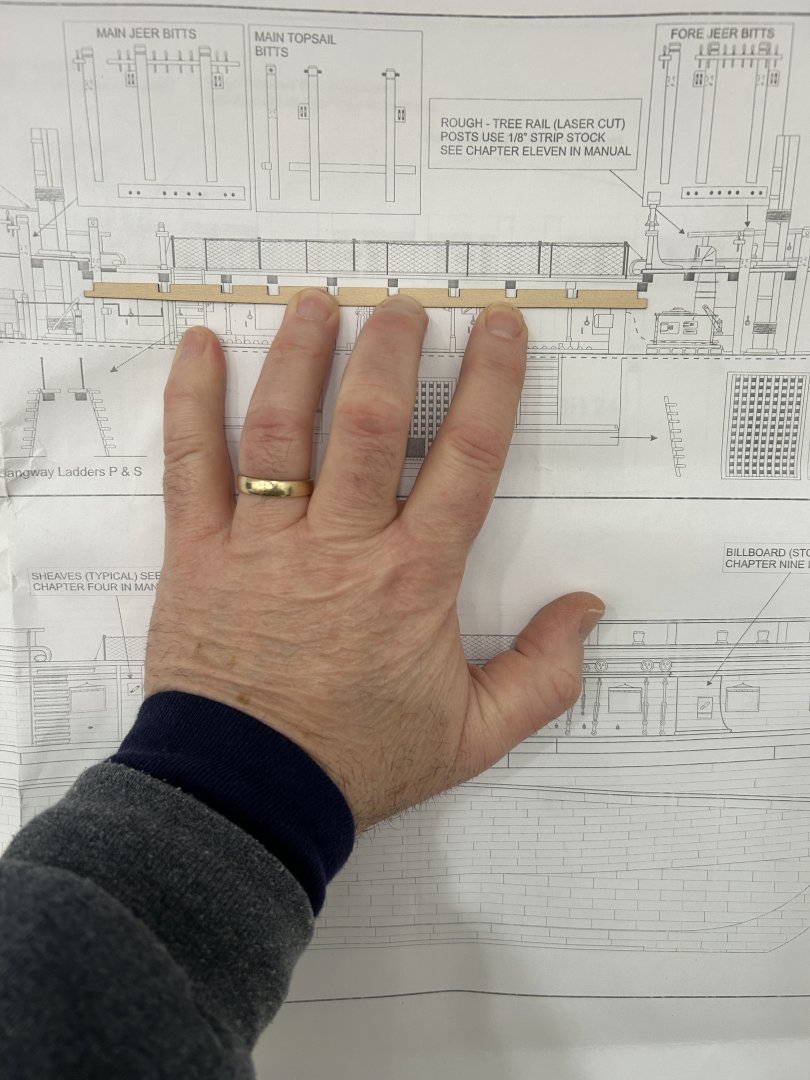


-
Krakord reacted to a post in a topic:
Buccaneer by Krakord - OcCre - 1:100
-
Buccaneer by Krakord - OcCre - 1:100
RossR replied to Krakord's topic in - Kit build logs for subjects built from 1501 - 1750
I like your weathered / distressed deck. -
AJohnson reacted to a post in a topic:
HMS Harpy 1796 by dunnock - Vanguard Models - 1:64
-
 dunnock reacted to a post in a topic:
HMS Harpy 1796 by dunnock - Vanguard Models - 1:64
dunnock reacted to a post in a topic:
HMS Harpy 1796 by dunnock - Vanguard Models - 1:64
-
Freebird reacted to a post in a topic:
USF Essex 1799 by RossR - Model Shipways - 1:76
-
Looks great as usual. Do you make the hooks or are they PE or purchased?
-
Paul White reacted to a post in a topic:
HM cutter Sherbourne by Maid of the Mist - Vanguard Models - 1:64
-
If you aren’t already following it, you should check out Ronald’s Sphinx build log. It is fantastic.
-
Good luck with this project. Looking forward to following along. you mentioned patience in your post and I feel like I was at a similar point after a couple of builds. Don’t be afraid to redo things if the aren’t quite right. good luck.
- 18 replies
-
- 1
-
-
- cutter
- Sherbourne
- (and 1 more)
-
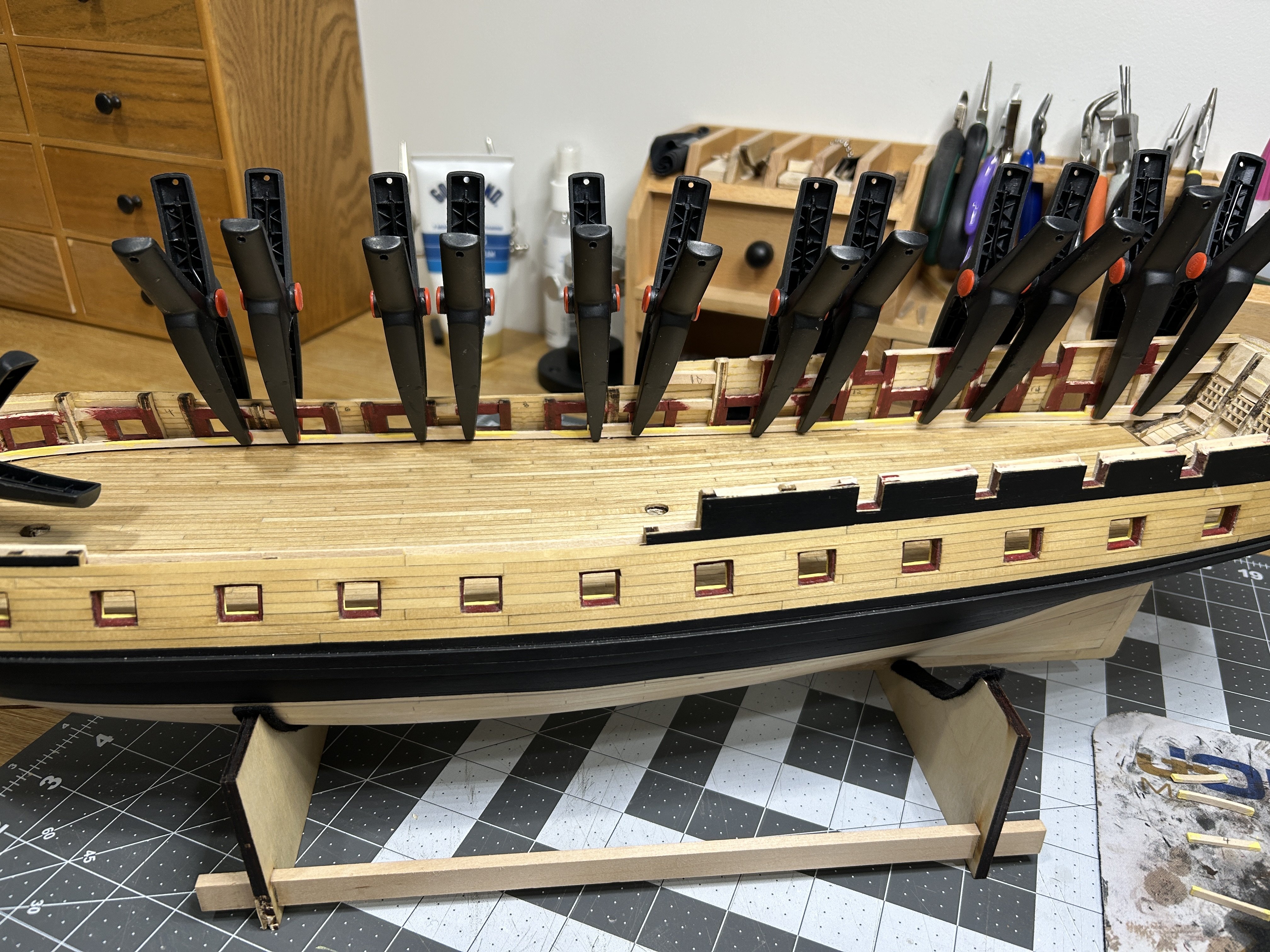
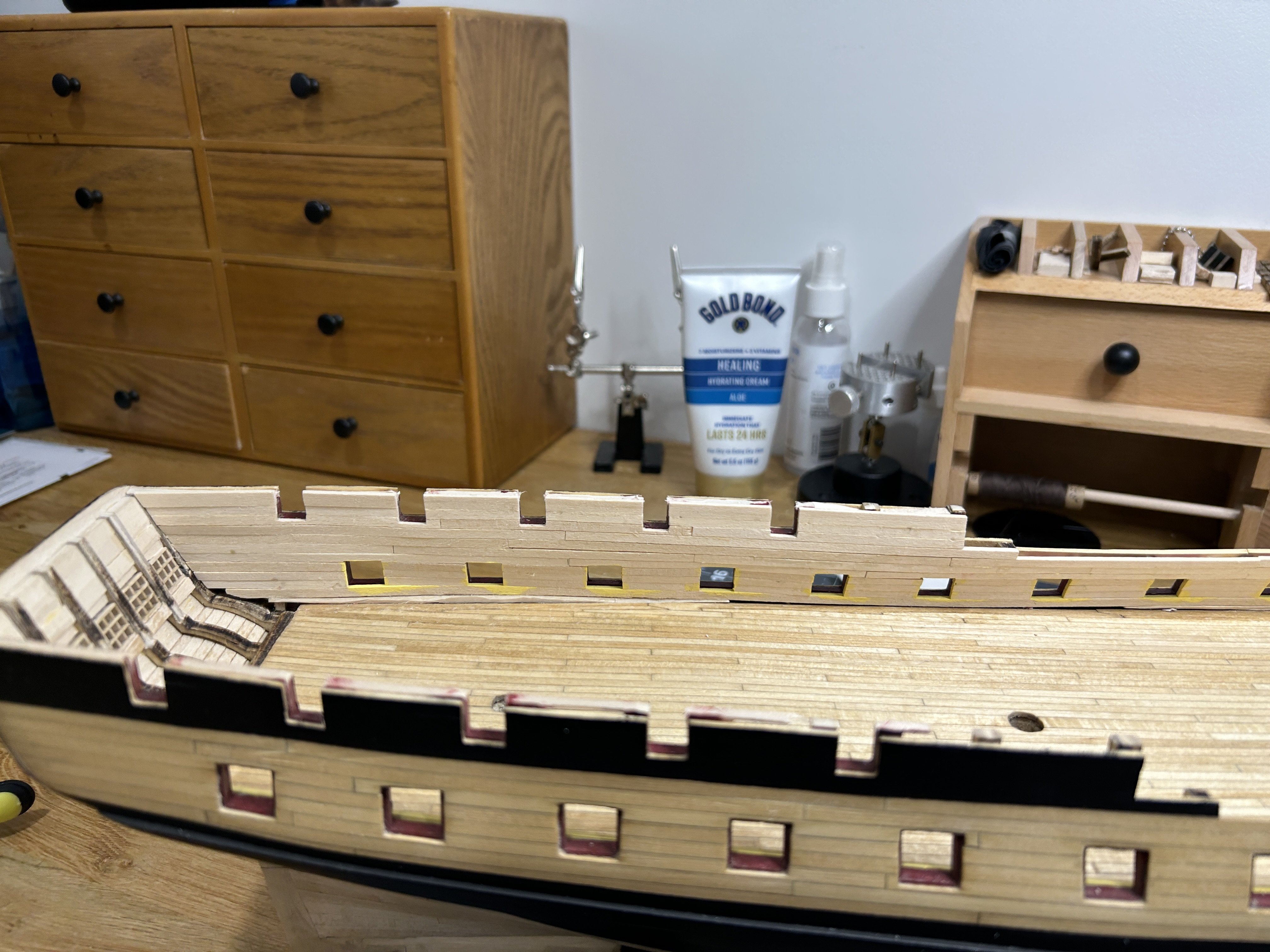
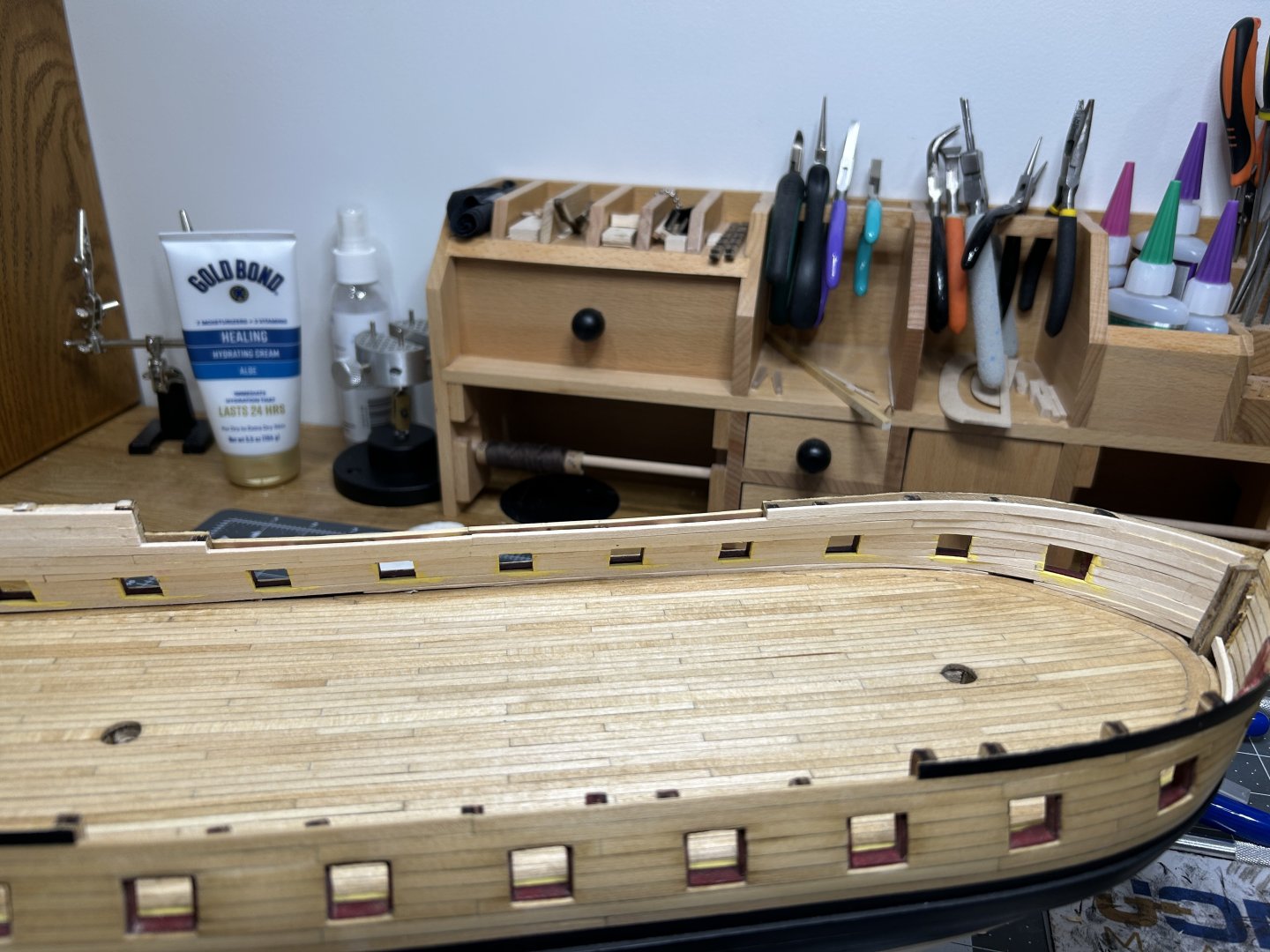
I have been making some progress planking the interior bulwarks. The instructions said to install the first plank as one continuous plank along the entire length of the ship with the top of the plank level with the bottom of the gun ports. The interior of the bulwarks at the gun deck level will be painted a pale yellow. The instructions were not clear whether the edges that are exposed at the gun port should be yellow or red, but some of the photos in the instructions indicated that they were painted yellow on the prototype. I went with painting them yellow and I chose to paint these edges before installing the planks to make it easier. I need to add some filler material in a few spots so that there wouldn't be any gap between the planking and the waterway which will be installed later. The planking around the quarter deck gun ports will be painted red as well as the bulwarks above the upper decks. I didn't paint those edges in advance since everything adjacent to them will be painted the same color. I have one side fully planked, and will be working on the other side and then the stern next. Thanks to everyone for the view and likes.


-
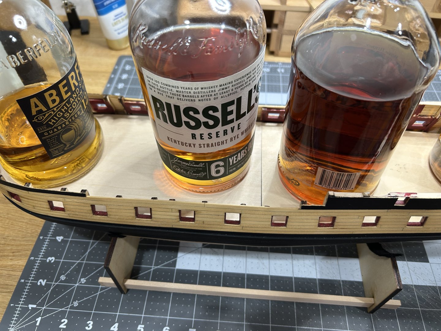
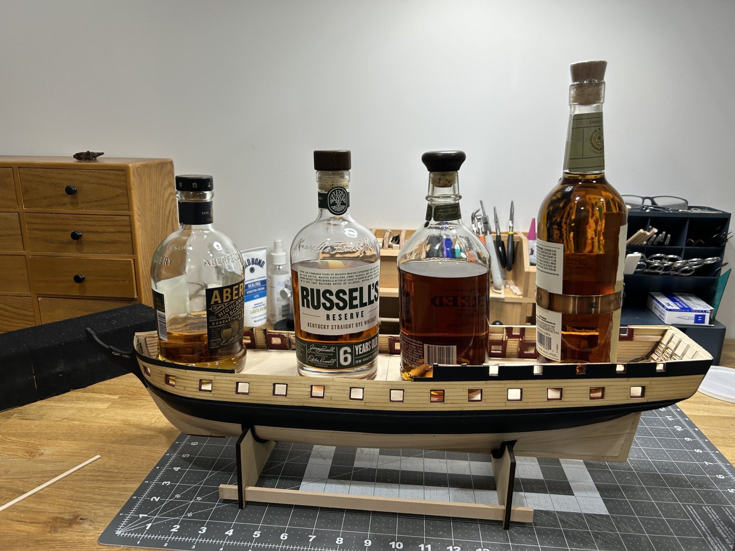
I will often use whisky bottles to weight down glued decks, but I also approve of your method. Looking forward to following your progress on this project.
-
Current Build: USF Essex - Modelshipways Completed Builds: HMS Beagle - Occre Frigate Diana - Occre Santisima Trinidad Cross Section - Occre 18th Century Merchantman Half Hull - NRG On the Shelf: Sultana - Scratch Build US Brig Syren - Model Shipways Albatros - Mantua
-
Glad you are starting up again. Looking forward to following along.
-
Cutters, Choppers, Guillotines, Slicers
RossR replied to MintGum's topic in Modeling tools and Workshop Equipment
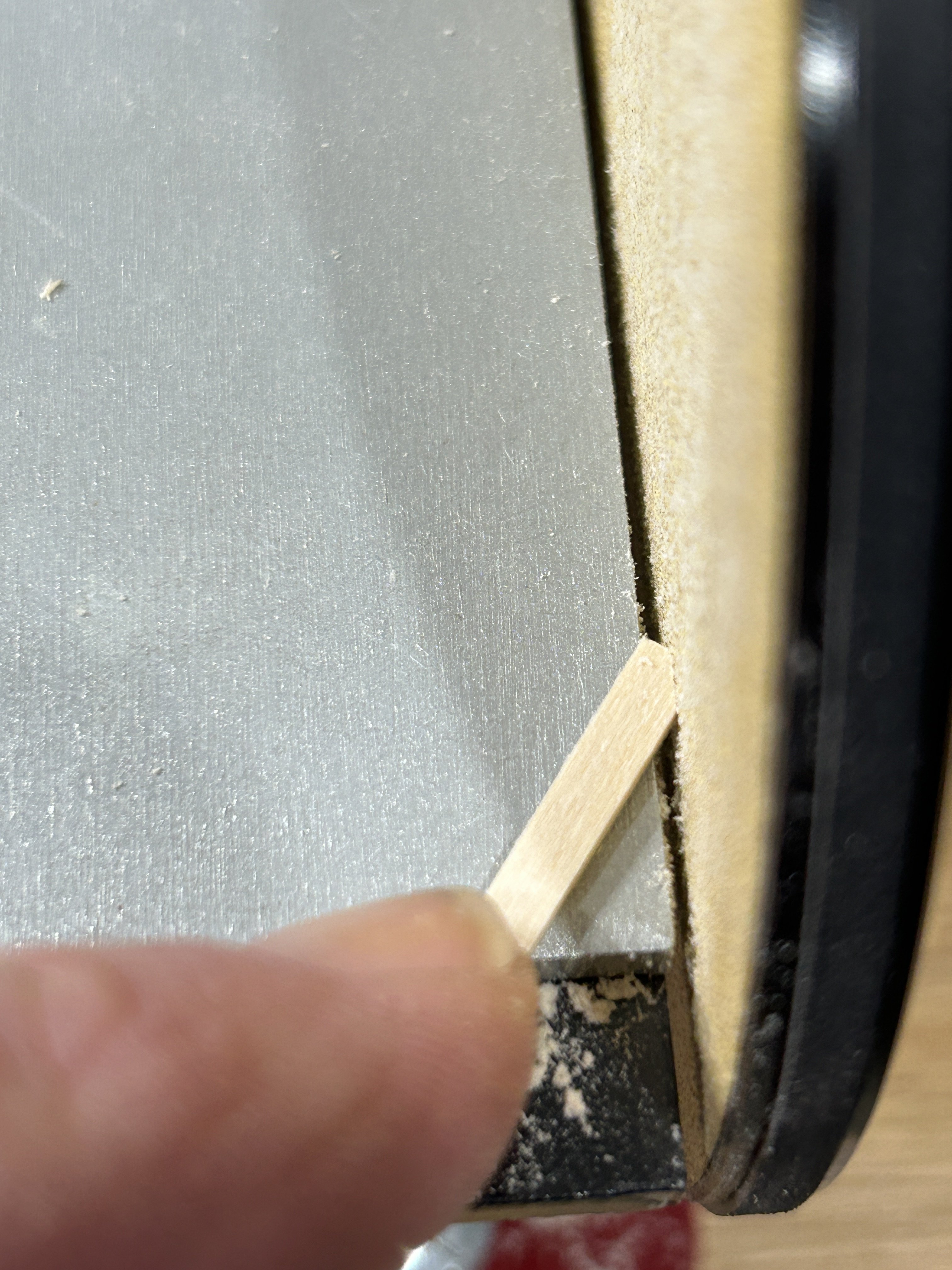
With the Ultimation slicer, for material thicker than 1/16, you would want to make your initial cut a little long the trim the final 1/32 to 1/16 off with a second cut. You will get a really nice square cut using this method. I also have the Ultimation sander and will often use that to square up the end. I don’t know if I would use the slicer on material 1/4 inch thick. I am sure it would cut it, but seems like it might be pushing the limit of the tool. When I have stuff that thick I cut with a had saw and clean up the end with the disk sander. -
I am currently building the USF Essex. The bulwarks on the gun deck will be painted yellow and the deck has been stained with honey oak stain. After the bulwarks are planked I will be adding the waterway. should the waterway be painted the color of the bulwarks, or should it be stained like the deck?
-
I have finished the rest of the Decking on the gun deck. I sanded it with 80, 120 and 220 grit sandpaper progressively. There were 3 or 4 spots that I had some gaps in my joggling. I used some stainable wood filler on those gaps. I finished the deck with Minwax Pre-Stain, then a coat of Minwax Golden Oak stain. After that two coats of shellac with a sanding with 000 steel wool after each coat. Next up is the planking on the interior of the bulwarks and then the waterway. Work will be really busy for the next 4 - 6 weeks so progress will be slower. Really happy that I have this deck finished before work gets busy.

-
Your painting of the PE parts is fantastic. The columns look incredible.
-
HMS Victory by ECK - OcCre - 1/87
RossR replied to ECK's topic in - Kit build logs for subjects built from 1751 - 1800
Nicely done. -
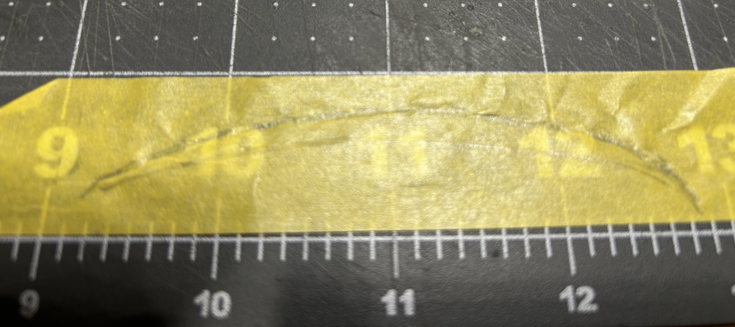
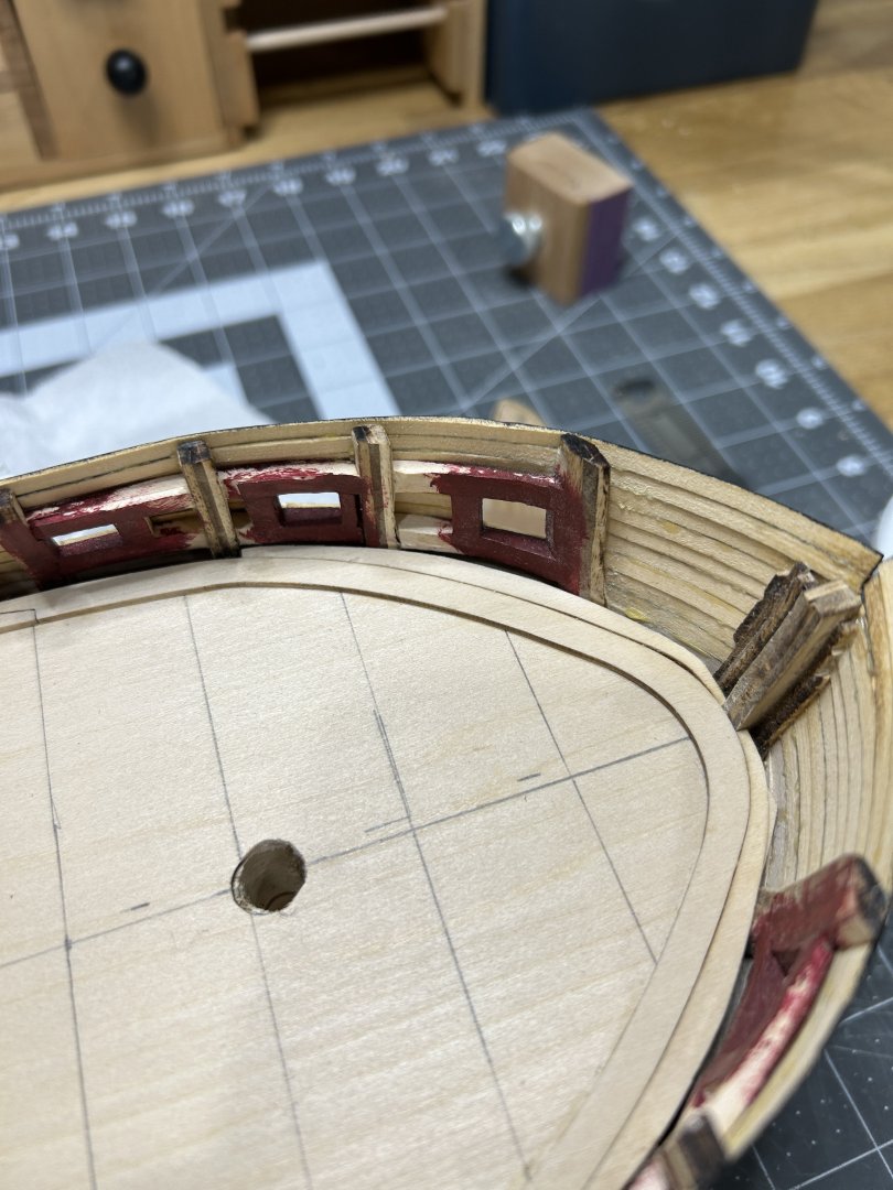
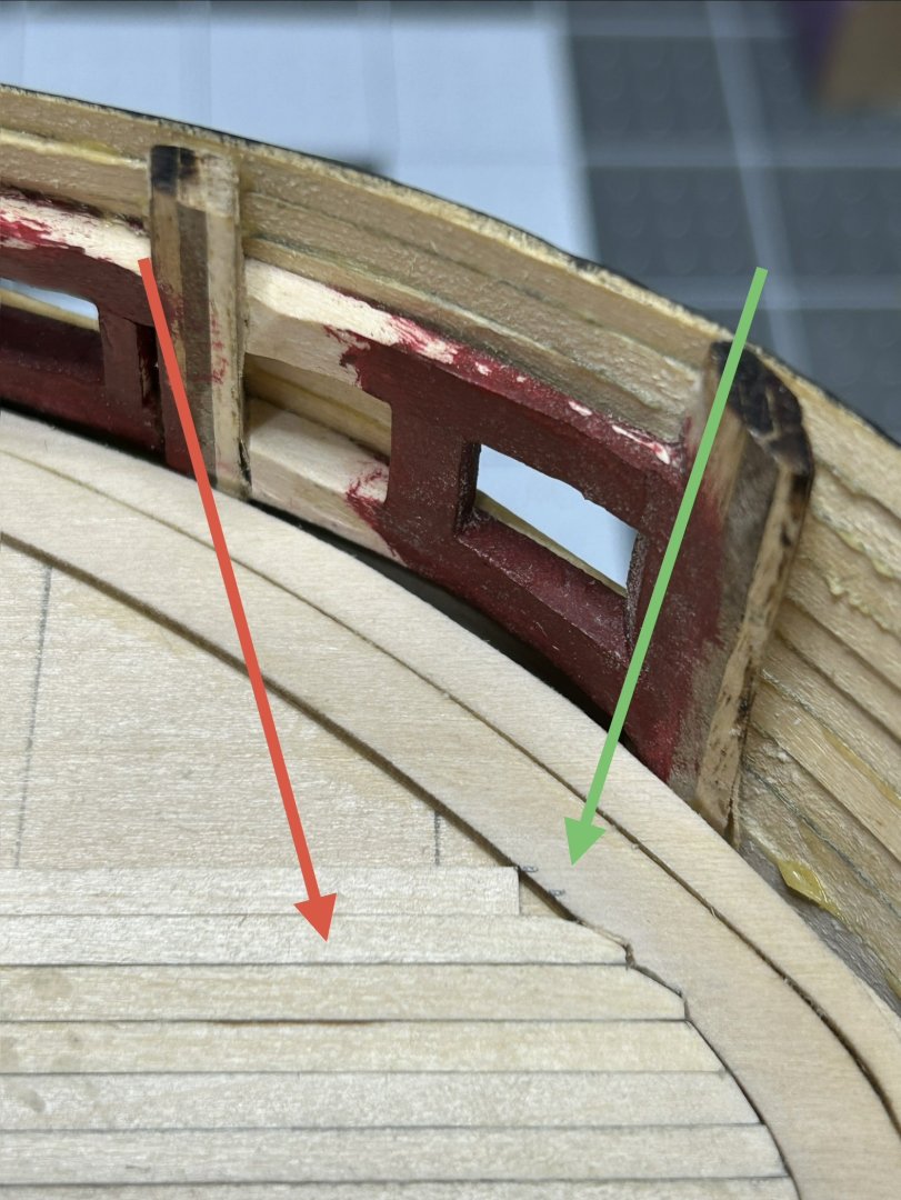
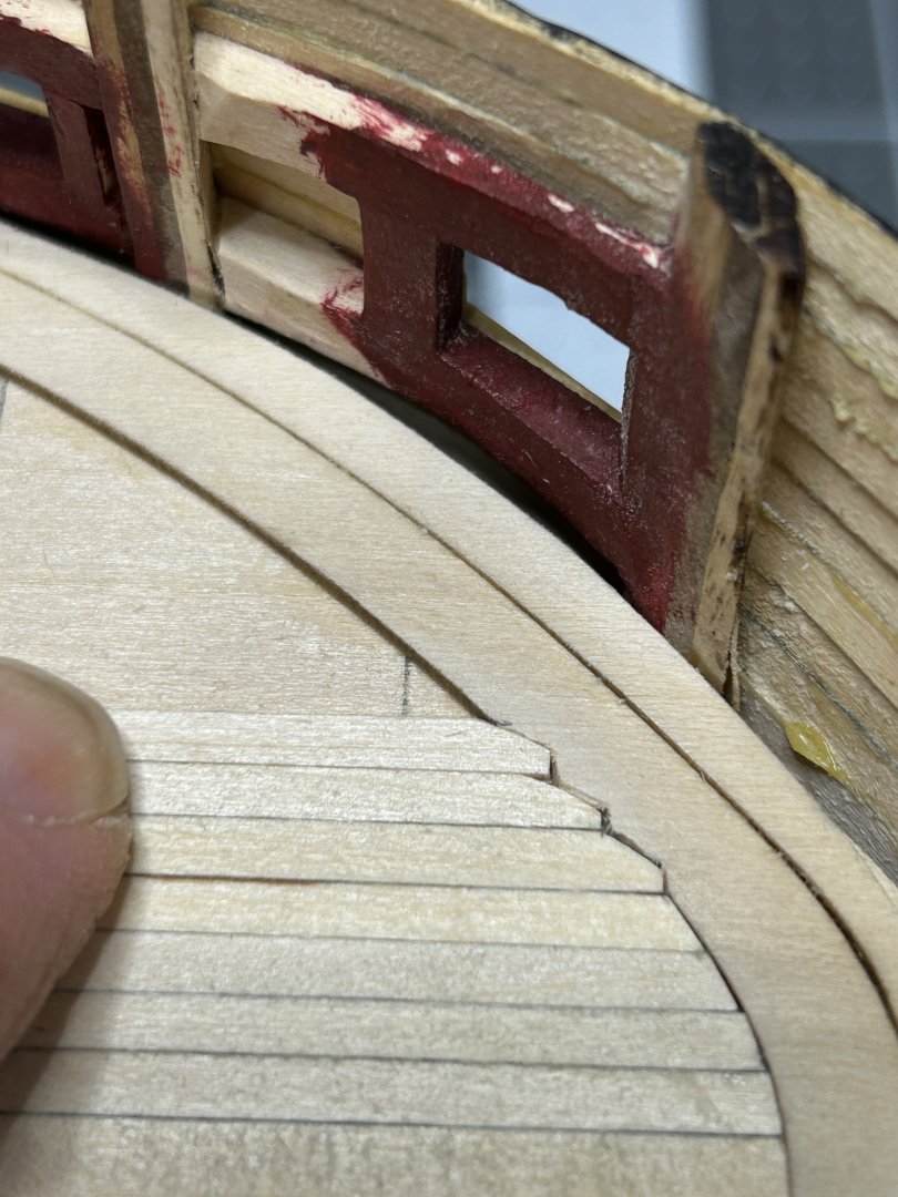
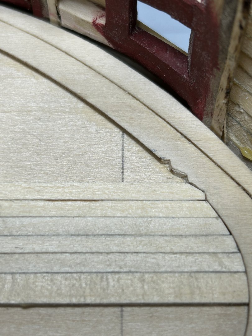
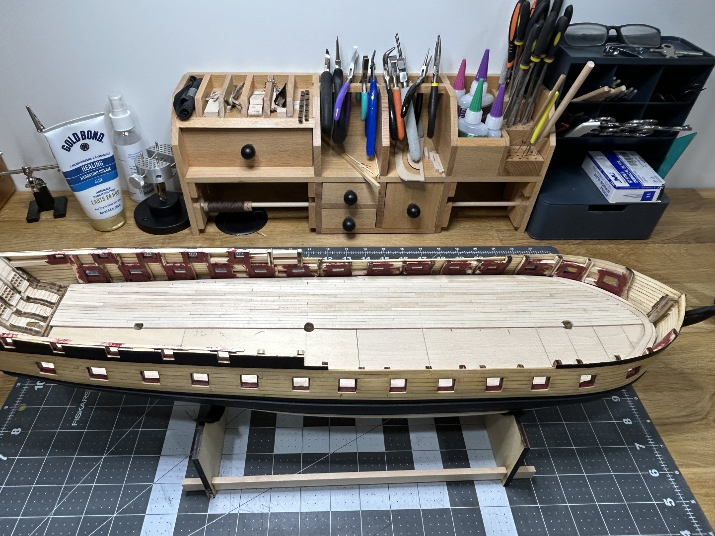
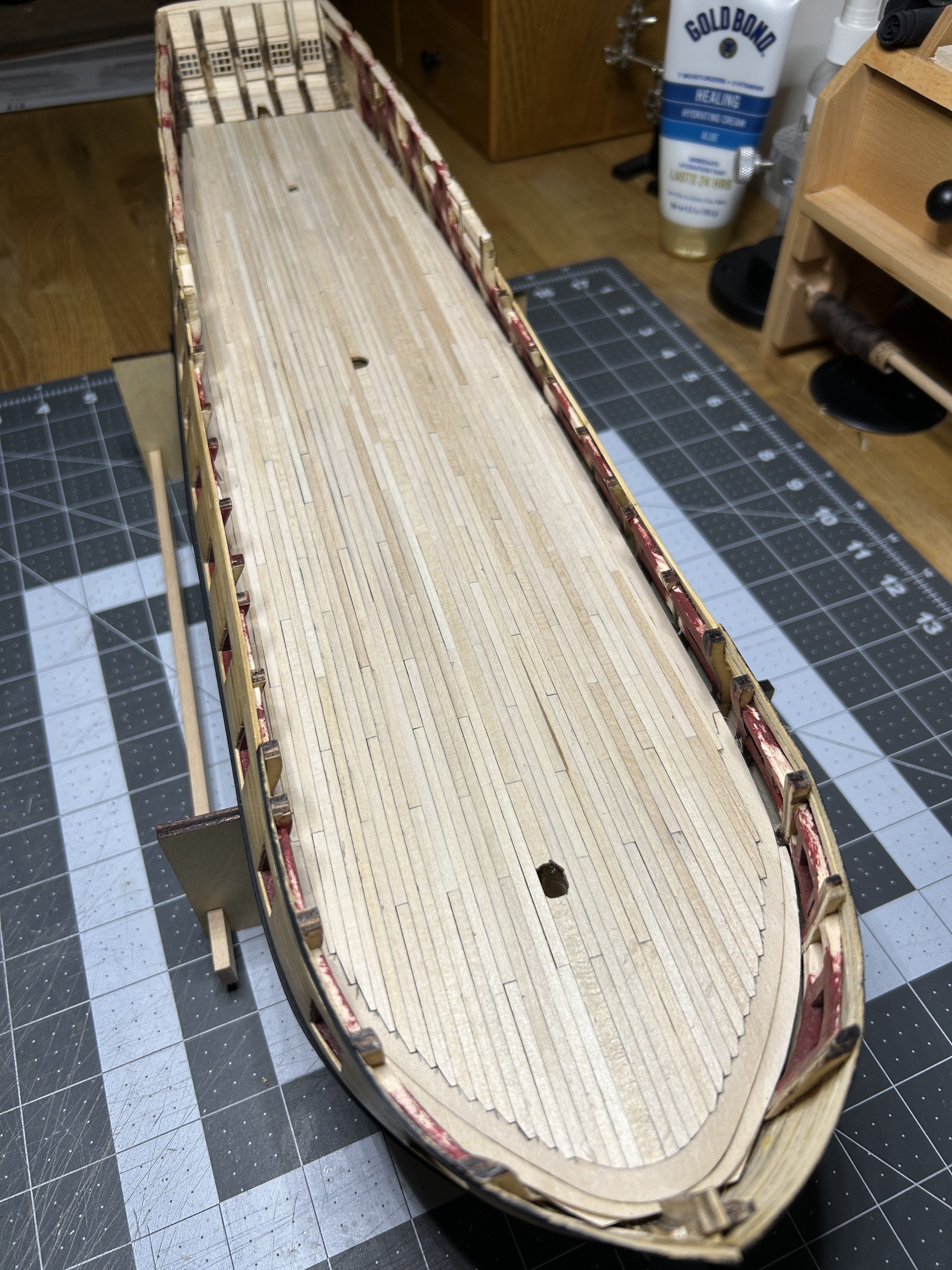
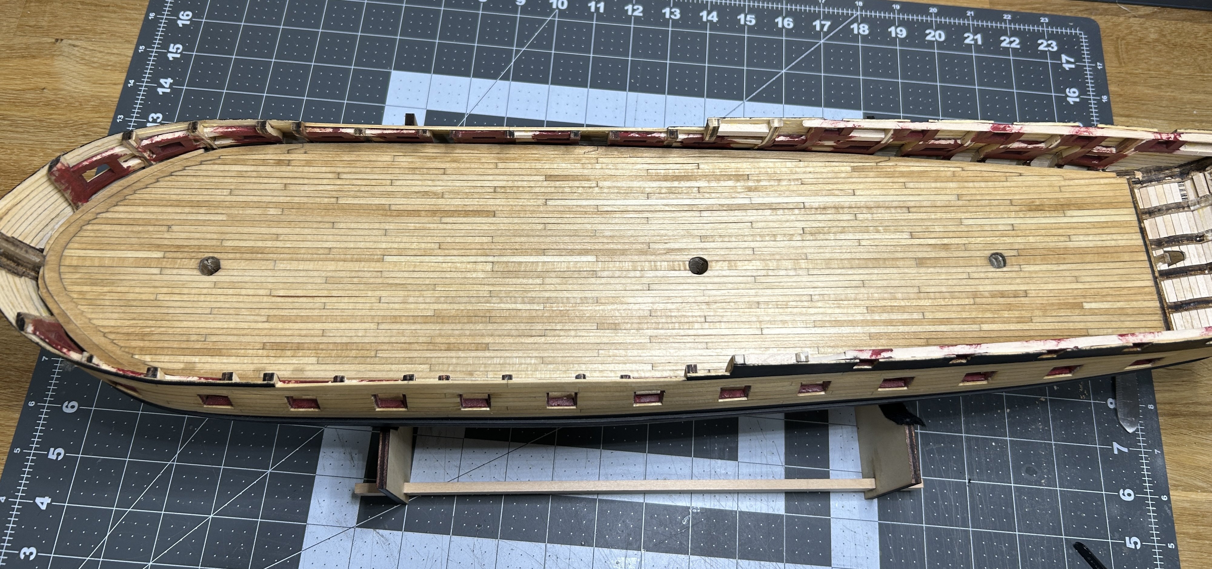
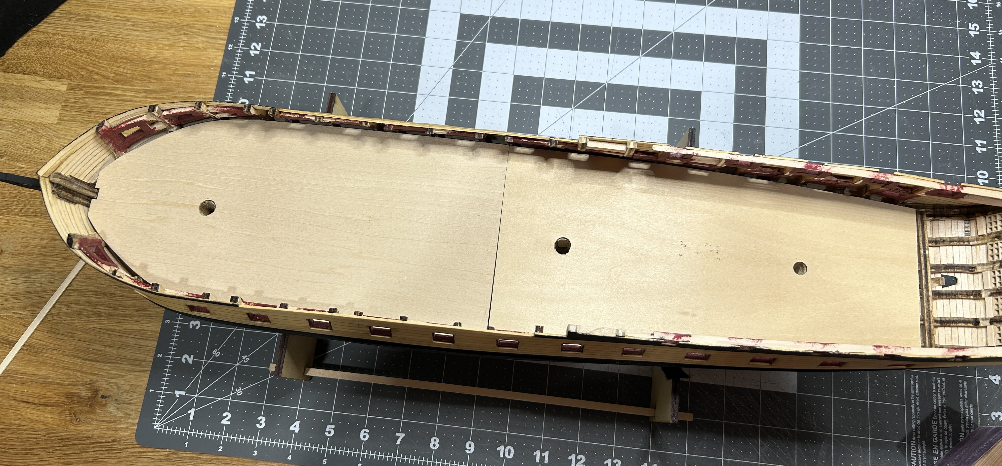
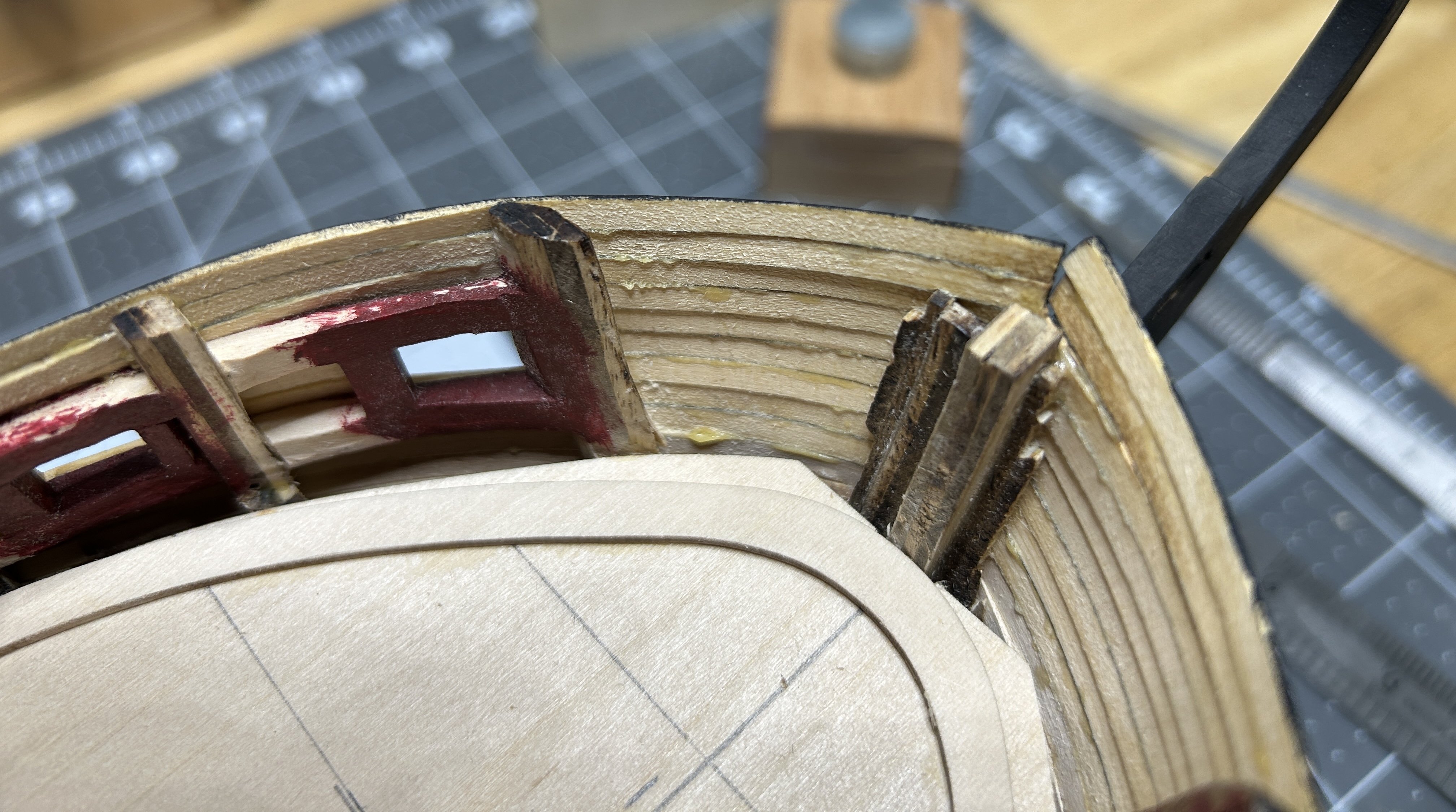
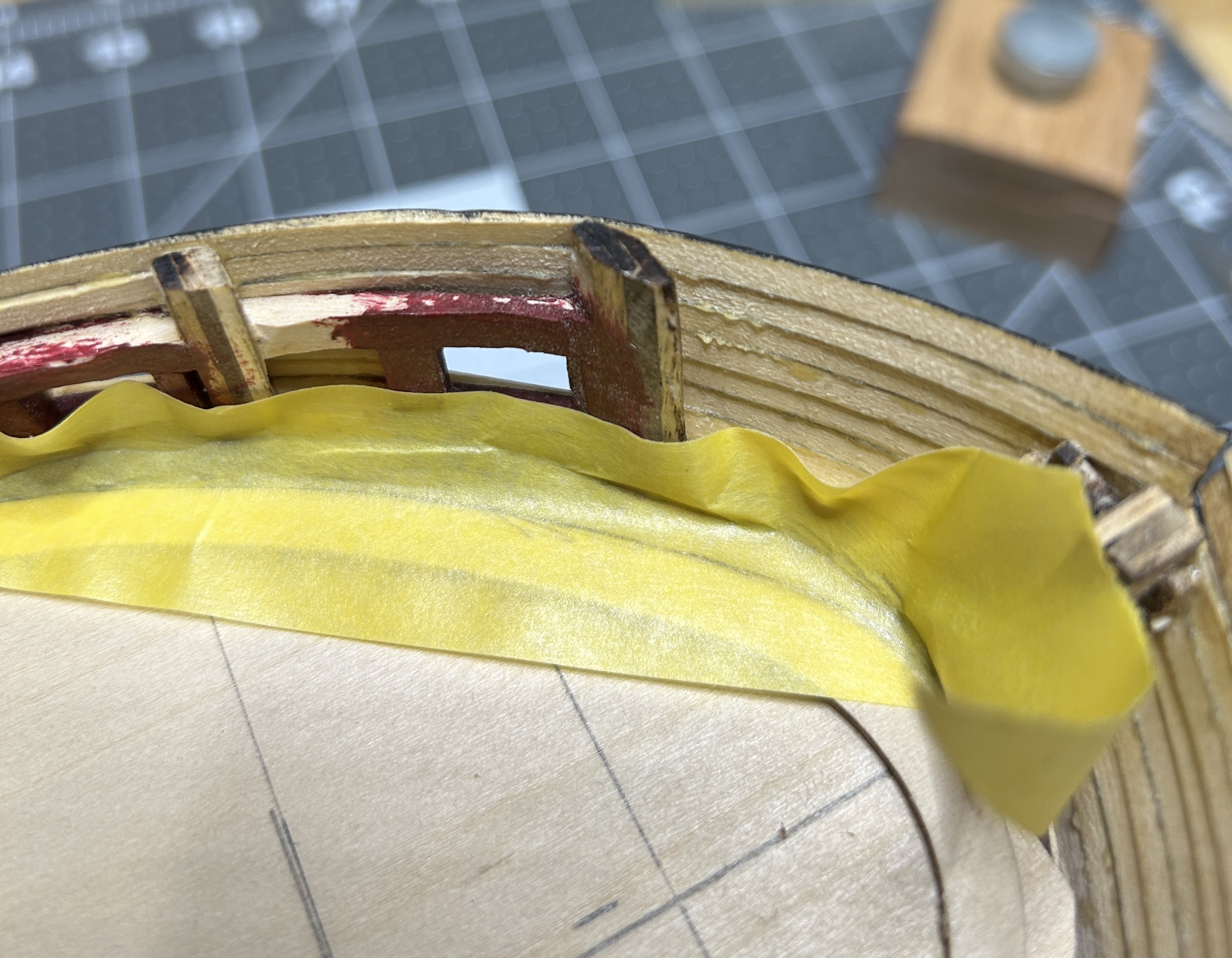
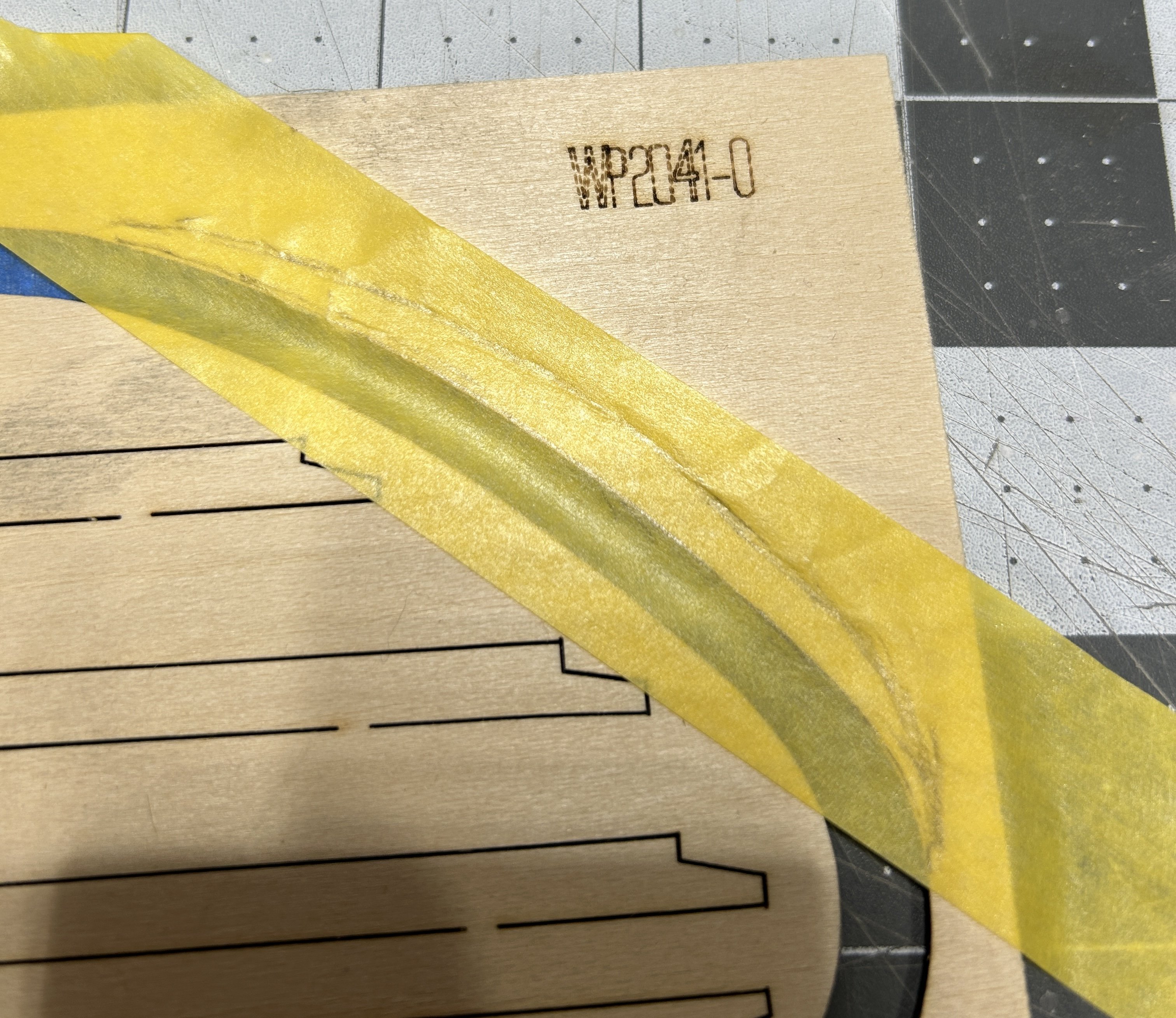
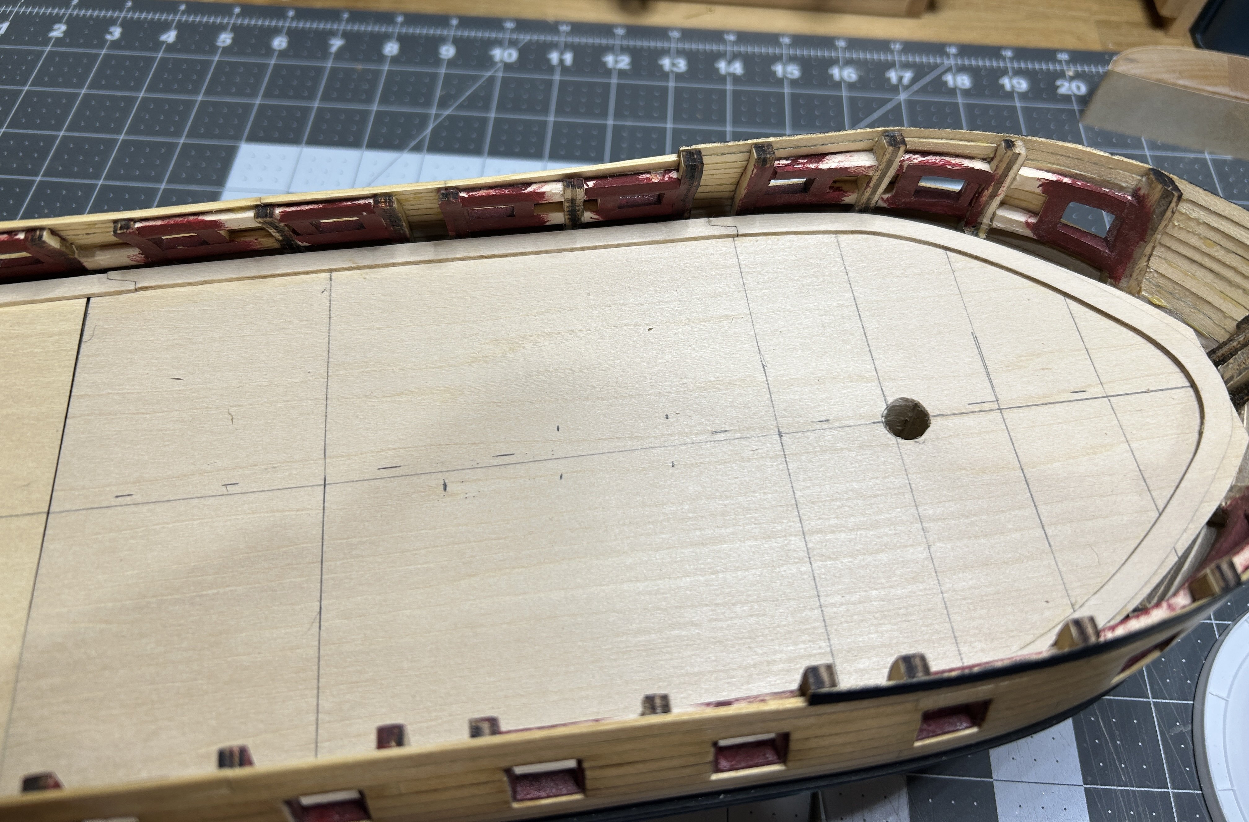
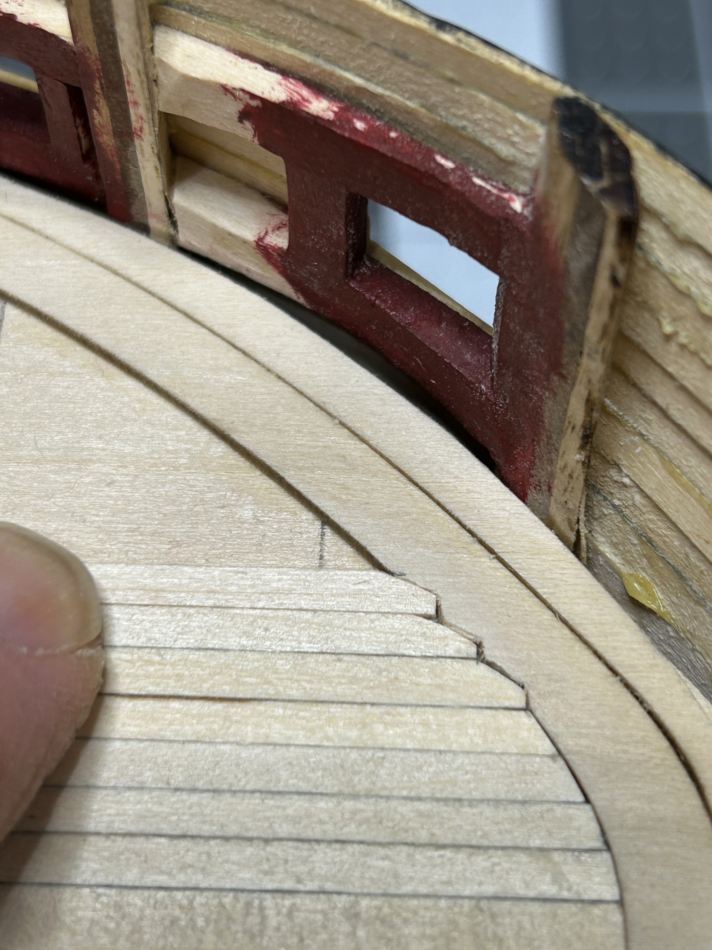
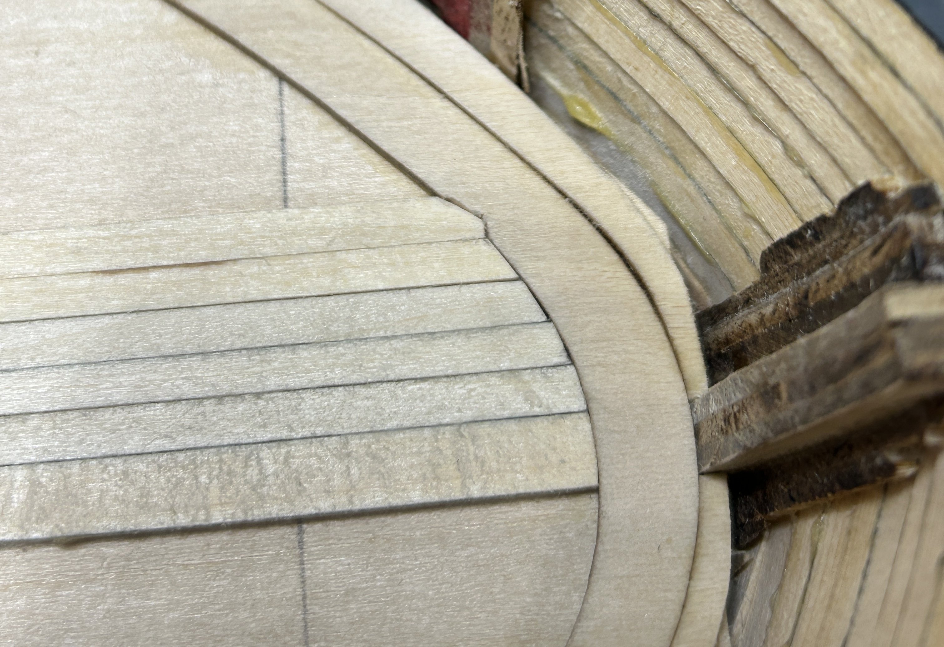
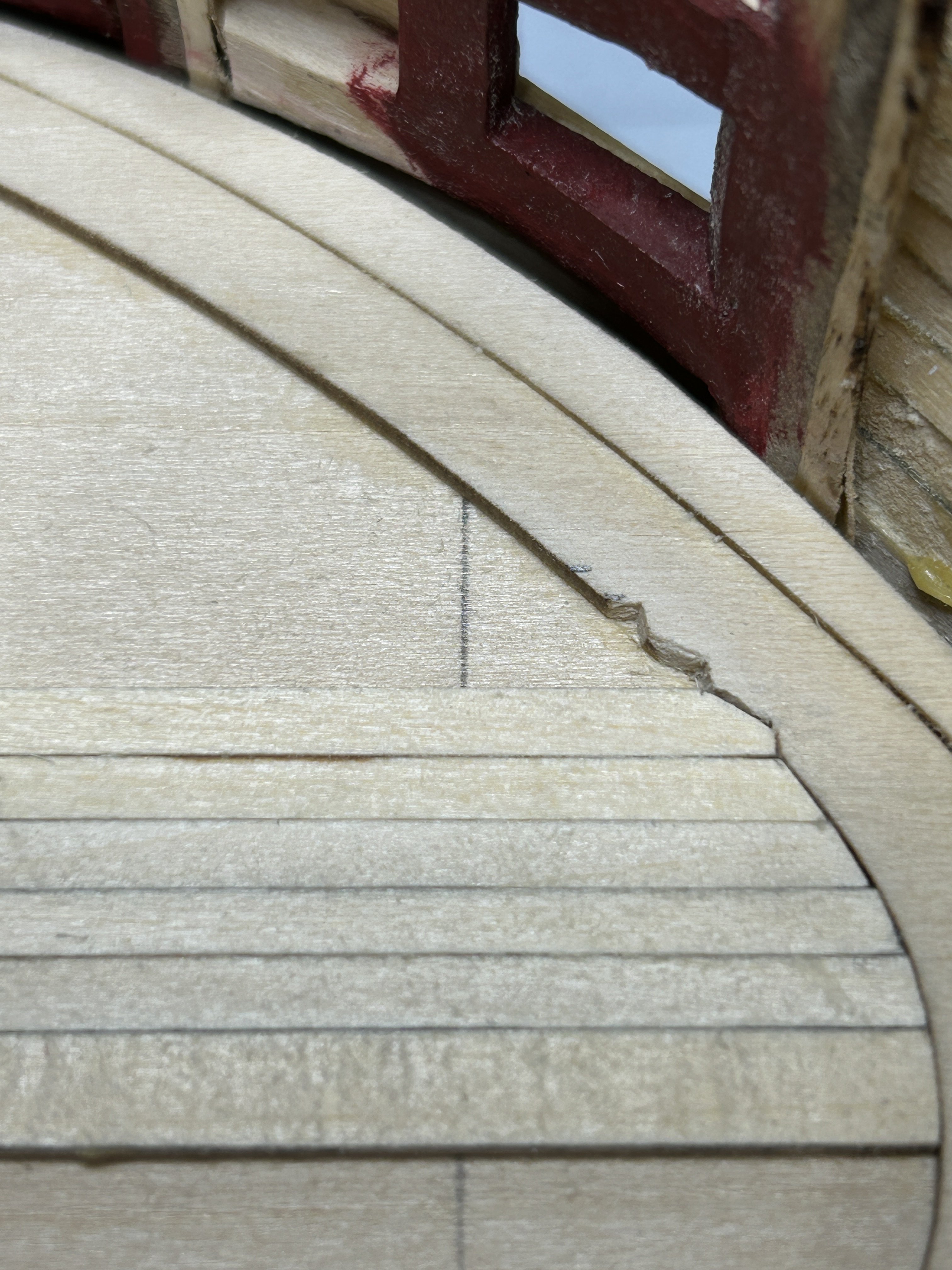
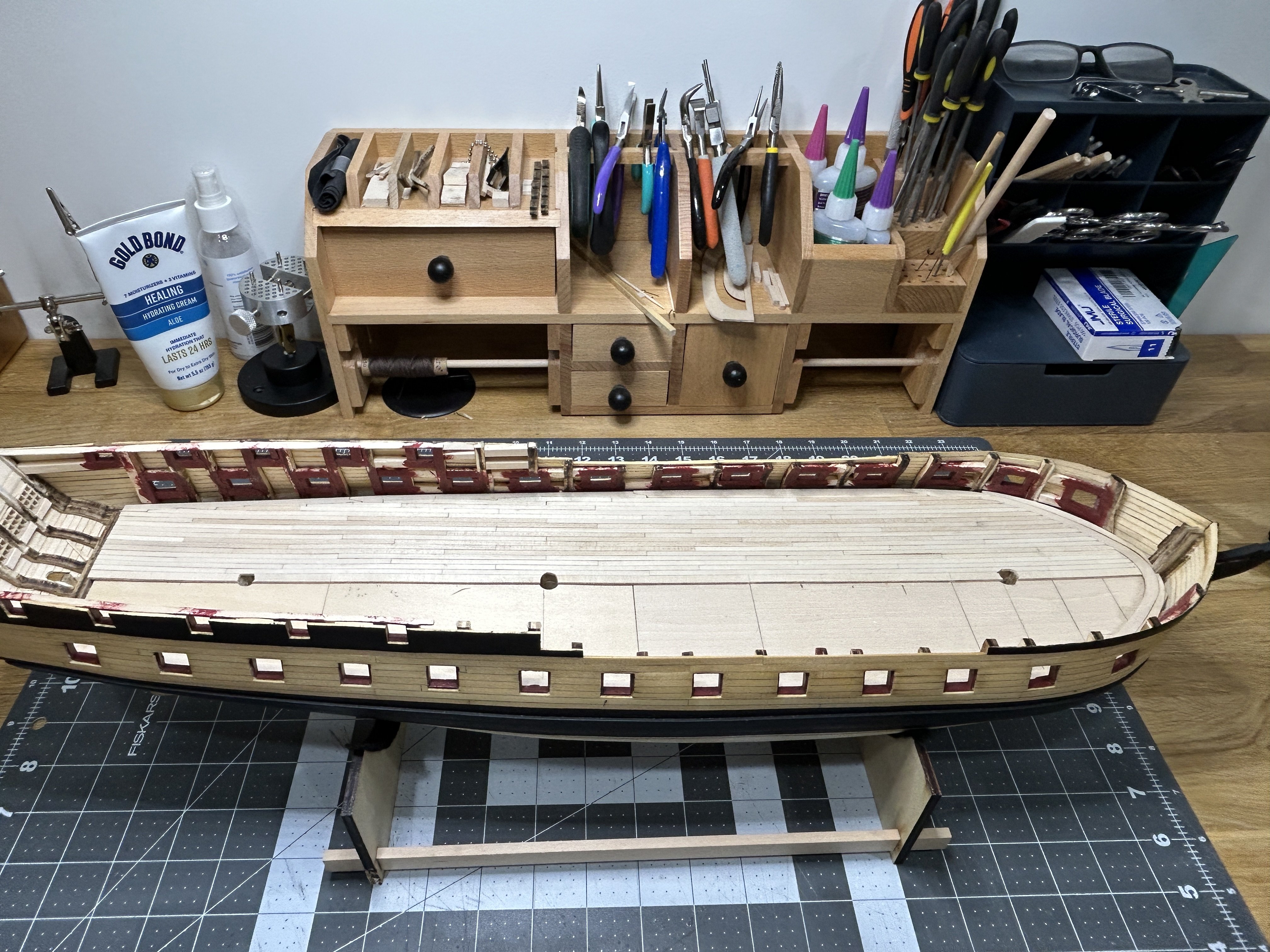
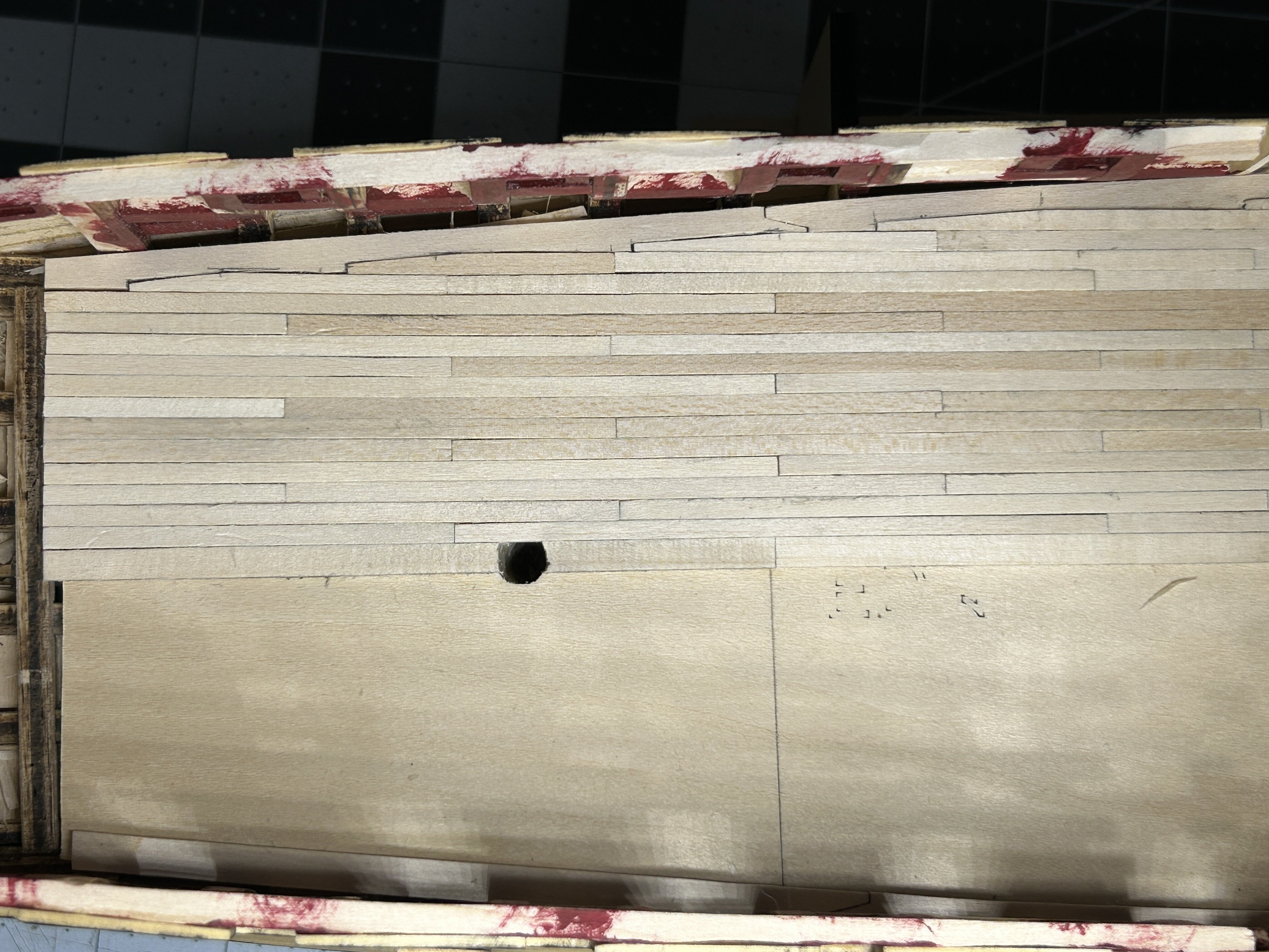
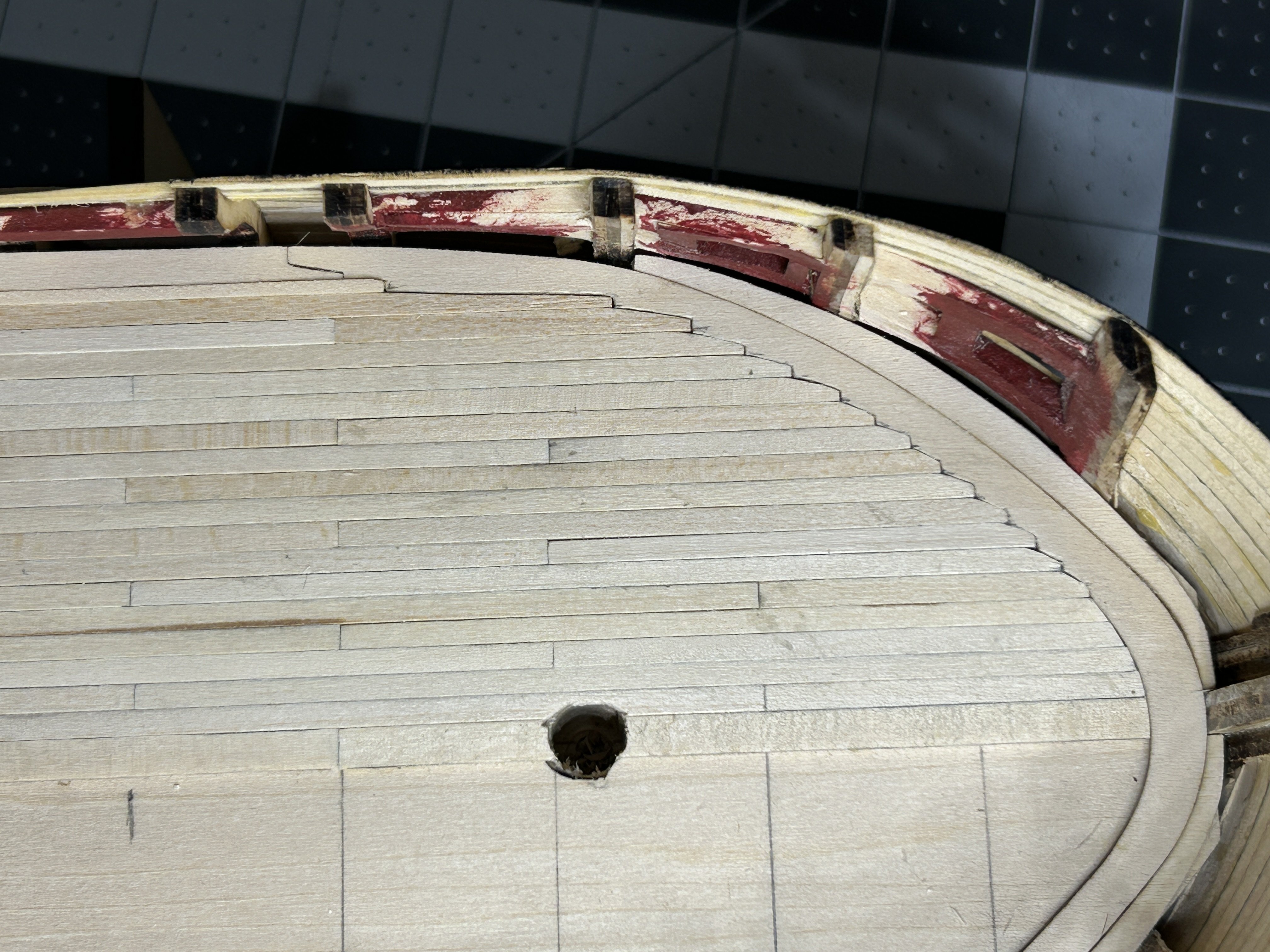
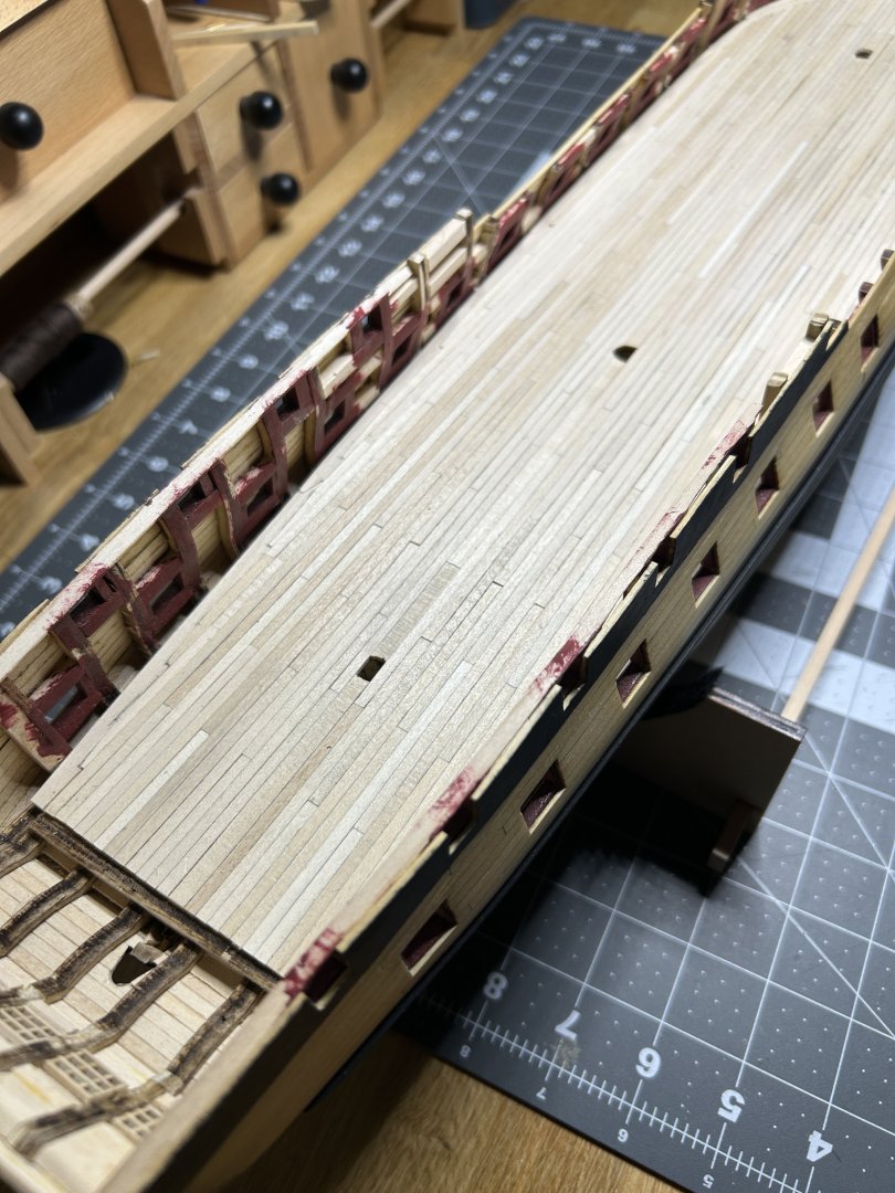
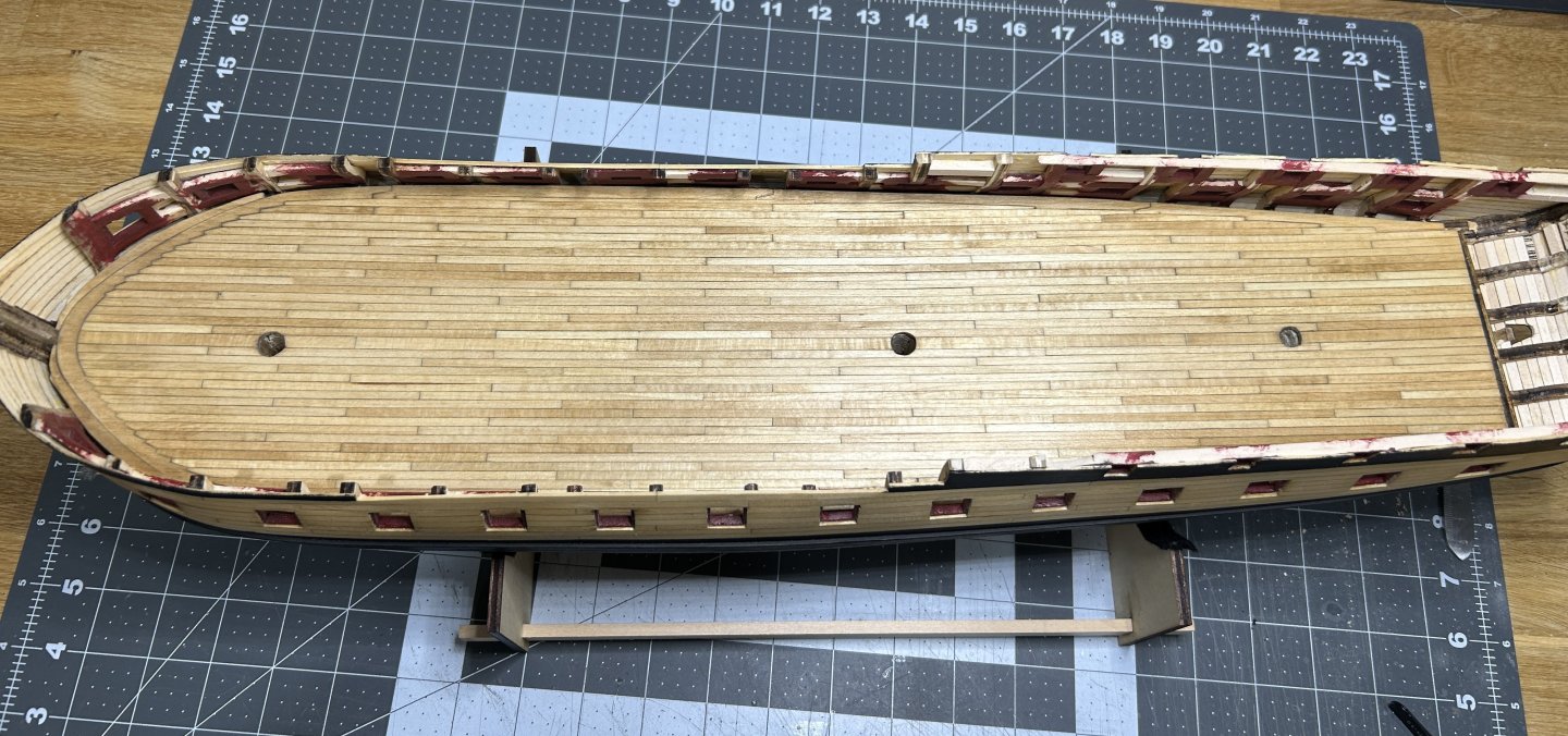
I have made significant progress on the decking of the gun deck. The first step was gluing the false deck to the gun deck. The false deck is designed to fit loosely and is not an alignment tool according to the instructions. There is a 1/16 to 1/8 inch gap along the bulwarks. I used some of my favorite weights to hold the two pieces of the false deck in place while the glue dried. I added the laser cut margin plank around the outer edge of the deck. There was recently a post on a build log for the US Brig Syren that mentioned an issue the builder had with the margin plank at the bow, and I had commented that I anticipated a similar issue with my build. It was clear that the way I faired the interior of the bulwarks would create a gap between the planking on the interior of the bulwark and the margin plank that was bigger than the waterway that will eventually be installed. I needed to add a piece forward of the margin plank. I used a piece of tape to help define the forward edge of the part that I need to create. I used the wood that the margin plank was laser cut from for the inside edge since it matched the margin plank, I only had to cut the outer edge which didn't need to be perfect since it would be hidden by the planking and waterway. The instructions call for applying all the decking in a single plank from stem to stern and to use a pencil to add the butt joints and treenails. I chose to use shorter planks to avoid having to draw the butt joints. I will pass on the treenails. I don't trust myself to be precise enough at this scale to make them look good. I made the same decision on the treenails on the exterior of the model. I chose to use 4 inch planks, which works out to about 25 feet at this scale. I added a line to the false deck every four inches as a guide and on every inch in the section near the bow. Since I was using individual planks I needed to ensure that the first row of planking down the middle of the deck was installed straight. I pinned a single piece of planking along the length of the deck and use it as a guide to add the king plank. The king plank is 3/32 x 1/16. The rest of the planks will be 1/8 x 1/16. The first four planks were angled at the bow to fit snugly against the margin plank. On the fifth plank I started to joggle them. This is my first experience with joggling planks. I will joggle the planks on the upper decks also, so I am glad I have the opportunity to do this on the gun deck first where my inexperience and learning curve will be largely obscured by other deck features and the partially planked upper decks. The image below is my first joggled plank. I worked out a process where I would only dry fit the adjacent plank (red arrow) so it could be removed to make it easier to cut out the portion of the margin plank that the plank would fit into. With the adjacent plank dry fit into place I would place the next plank as shown (green arrow) and mark to out edge and make another mark approximately 1/2 way between the edges of the planks. I would then make a cut at a ninety degree angle from the outer edge of the adjacent plank approximately 1/3 to 1/2 of the width of the plank. and then another cut that was parallel to the length of the plank. Then I would connect the right angle created by the two cuts and the mark I made at the outer edge of the blank. I used my disk sander to shape the planks to fit. I continued this process outward from the bow and then back towards the stern. I have completed the port side and I am very happy with the results. It will need a little sanding and possibly some spots that need to be filled with wood filler after I get the starboard side complete. I have really enjoyed this process. I know a lot of kits come with decks that have laser cut images of the planking eliminating the need to plank a deck like this. These decks look fantastic, but I am happy to have some imperfections in exchange for the experience of joggling the planks. I was nervous about this step before I started partially because there are no instructions that show you where to cut or how to lay out the joggling towards the stern. I took my time and everything came together fine. I will be getting started on the other side and then get it sanded, stained and sealed.