HOLIDAY DONATION DRIVE - SUPPORT MSW - DO YOUR PART TO KEEP THIS GREAT FORUM GOING! (Only 24 donations so far out of 49,000 members - C'mon guys!)
×


Doreltomin
-
Posts
250 -
Joined
-
Last visited
Content Type
Profiles
Forums
Gallery
Events
Everything posted by Doreltomin
-
Hello, I have used this trick of blowing up the lines using a photostatic copier with blow-up capabilities many times. This drawback of having big black lines I solved by putting a sheet of clear drawing calque over and re-drawing the lines again, otherwise it will result in a mess. I did not invert the colour as you did, only used a coloured pen (usually, red) over the thick black lines to redraw over. Good luck with your build(s), will follow you with interest, these drop keels make an interesting feature of which I have wondered the details several times.
-
Hello, as Kester says putting a picture will help a lot in figuring the exact problem. Otherwise, like that "on the blind" it seems that you have a plank on bulkhead hull with a keel not stiff enough. You may need first to take the deck out to have acces inside the hull, then you will need to devise a way, something like a cradle or a jig to fix the hull in the proper position. Even fixing the hull on your tabletop, provided it is stiff and perfectly flat will do the trick. Then you will need to insert some stiffeners inside the hull to keep it in the correct position even after it is removed from the previous fixture. I believe you can try cutting two squares of plywood of the proper distance between each space between bulkheads and then securely glue two of them each side of the keel put so that they would form a "V" in transverse section touching the keel, the angle between the two sides of the V being roughly 90 degrees. After glued properly to each bulkhead they will be stiff enough to block any twist movement of the hull. Good luck and show us what you did! Best wishes,
-
Hello Alan, I took my own copy of Wolfram zu Monfeld "Historic Ship Models" and opened it at page 66, and found the said list of different measurements. I believe we have the same book, is it the one published by Sterling Publishing Co, Inc. NY? There's indeed a list which gives the English foot to be 308.0 mm, but I wonder if this is right. To my knowledge, the dimension of English foot did not change at least from the 17th century until nowadays, so if they did change anything into the 19th century it was the way they "translated" it into a meter, not the dimension itself. Moreover, in my calculations I always use the English inch of 25.4 mm yet I have an old Hütte engineer's manual which I have inherited from my father which gives one English inch to be 25.399956 mm. The difference is very small, yet as you said, if you add many inches together, it can get a significant amount. This only happens if you work your model metric and always try to "translate" your measurements from the old imperial units into milimeters. Here is the really nice part when working with imperial units: if you use an imperial scale and use a measuring tool divided in inches and fractions of an inch, working for example your model to a scale of 1' = 1" your model will always be true to its scale of 1:12. Moreover, if instead the English foot you will use a measuring tool divided into French feet or Swedish feet to measure a plan which is made into these units, the model will still be 1:12. Of course, this only works if that unit is sub-divided into 12 inches. It will not work for the Amsterdam foot which was divided into 11 duimen. Don't ask me why, and moreover, how on Earth they managed to divide that foot into 11 equal parts So if using a different foot or a different way of translating your foot into milimeters, your model will still be accurately proportioned (supposed you made it accurately) only the scale which you know to be a true 1:48 may in fact be 1:51.5 or 1:46,79 or something like that. It's just a question of numbers. This applies as well with the old Navy Board models, many of which are known to be built in 1:48 scale, yet if measured carefully, some of these models show not to be built at a true 1:48 scale but to a slightly different scale, depending on which measuring tools the model maker used and how accurately these tools were made. Here: http://en.wikipedia.org/wiki/Foot_(unit) you have an abstract of the measuring ways used in Europe from the early times (it is a wiki source so use with the due caution as it is known for the wikipedia sources not to be always reliable) and here: http://www.historiaviva.org/cocina/medidas_v2-ing.shtml a review of the measuring system in Spain in early 15th century. Hope this helps!
-
http://www.archaeology.org/exclusives/articles/648-yenikap-byzantine-serci-limani-turkey @Louie, didn't know of this extraordinary find in Yenikapi... Thank you, very interesting informations! Together with the venetian ship and the roman wrecks in Pisa, this may be one of the most significant finds in the last years to shed light onto early ships from late roman, early byzantine era!
-
Hello Kevin and Eamonn, that's what I love most to this game, it gives you a good opportunity to find out things about various ships with so interesting histories. Thanks for posting that! @ Titanic: please, come in and have a seat.. it's free for everybody to guess the ship and, if you guess, then you can post the next one! Cheers, Dorin. P.S: Kevin, don't forget it's your turn!
-
Hello, very interesting, Ab Hoving is a well known modeller and historian and his books are a must for people interested in Dutch ships. Thank you for sharing this exciting news with us! Here's the link to Seawatchbooks: http://www.seawatchbooks.com/113004
-
Excellent, congratulations DFellingham!!! She is indeed the Romanian cannonboat Grivita built on the Fiume yard which then was in... Austro-Hungaria, So Jan, I am sorry, you were just an inch close of her, but picked instead the wrong lady. Fulgerul (The Lightning) was built on the French yard Forges et Chantiers de la Mediteranee, la Seyne, Toulon in 1873 and looks quite different. If you do a quick search with her name you will get at least two of the three known pictures of her. DFellingham, it is your turn to put in the next mystery ship!
-
Hello Ron, In the meantime I had the time to check in my collection of old magazines. The Benjamin W Latham appeared in the former East German magazine Modellbau Heute number 11/1989 (which is, november 1989) and is a well researched topic written by Michael Sohn which includes several photos of the original ship, all credited to author's own collection. One even shows the ship being built on the John Bishop yard in Gloucester. It may well be that the plans are drawn by the author and are based on his own research. Whether the author also studied the Ronnberg plans I cannot say but it's a clear thing that they are different from the one on which the Model Shipways kit is based.
-
Now you are getting really close! C'mon Jan, a little effort, you are really on her, there's only a little twist of the tale
-
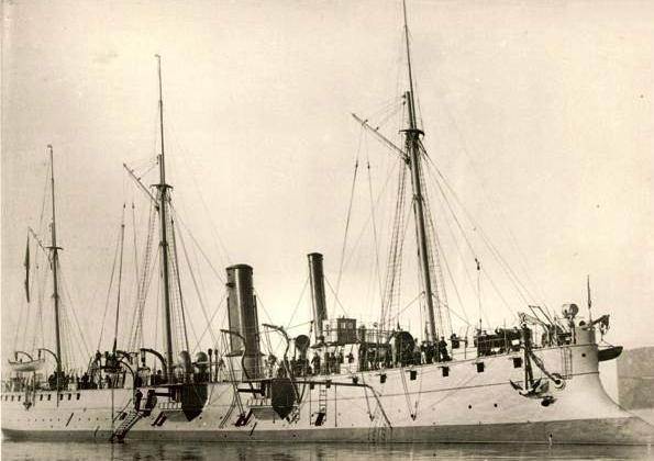
Hello Jan, you got the right type of ship, about right in time, but not too close in location... at least you guessed the continent! I might also add this white livery is not the original one, this is one of the last photos of her, taken sometimes at the beginning of the 20th century. Originally she was black.
-
Hello, Thank you David! So I believe it's my turn to put up a photo again. Here she is, our next mystery ship. As usual, I have tampered with the flag for the beginning so don't try to recognize her by this feature!

-
French cruiser D'Estaing of 1879, La Perouse class?
-
ROYAL CAROLINE 1749 by Doris - 1:40 - CARD
Doreltomin replied to DORIS's topic in - Build logs for subjects built 1501 - 1750
Hello Doris, that's a very nice helmsman you have there! I am as always impressed by your talent and your attention to detail. Therefore, just as a help for you to make the things look more realistic and not as a criticism of any way, please find attached a sample made putting together details from two different Willem van de Velde drawing depicting people aboard two of the yachts of King Charles the 2nd of England. Even if the drawings are about one hundred years earlier, I believe the sailor's clothes would have been the same. As you can see in the drawing, the crew usually had a long mantle with sleeves, long pants and always wore tarred hats to protect themselves against the wind, sea and sun. Moreover, I believe the position of the long wooden pole connected to your yacht's rudder may be too raised up. It should have been made parallel with the deck and going just above the deck light in such a way that the metal ball terminating the rudder post would be at the proper height for being grasped by the helmsman's hand. Hope this helps.. anyway, you can as well leave everything just as it is, it looks stunning anyway!
- 883 replies
-
- 2
-

-
- royal caroline
- ship of the line
- (and 1 more)
-
Hello, that's very interesting.... looks like a cargo boat still she has some places for passengers too. And I can see at least four safety boats at a side, which makes it at least eight boat for the whole ship. May seem this is after the Titanic disaster. The ship itself looks as if built between 1900 and the beginning of the first world war, but have no idea yet on how to pinpoint her.
-
Hello Don9of11 (That's a funny nick you have there!) Thanks for posting your mosaic photo support, it illustrates perfectly what I wanted to say; which is, you don't need to put all the support picture under your vectorial plan at a time, you can put only the relevant part and draw it, then close and put in the next etc. It's easier to do that if you intend to draw all the plan in vectorial, because the bitmap image plan actually uses a lot of resources for the drawing, has to 'map" every point of the image, while the vectorial only uses the coordinates of the start and the end points of a certain (straight) line. This way you will have a full plan free of any distorsions which you can later print and use for your modelling purposes. Best wishes,
-
Hello, I have managed to fix such bended plastic pieces by dipping them into very hot water (actually, boiling) and setting them to the correct position with two pliers. It also may be a good idea to try the technique on a piece of sprue to set the correct temperature before doing it on the actual piece. The boiling water is hot enough to make your piece pliable yet not that hot to make it lose its correct shape. I would not try heating a plastic piece in another way; it may melt or, even worse, can ignite if heated too much.
-
Hello Congratulations Jan, she is indeed the Cosmao, built by the Chantiers & Forges de la Gironde, Bordeaux, set on keel in 1887, launched in 1889, put on service in 1891 and offered to scrap in 1919! I am pretty impressed that you were not confused among the many French second class cruisers (they had 24 of them, starting with the Forbin of 1888 and ending with the Infernet of 1899) and picked the correct one! So.. your turn!
-
@ Jan: You are right, some of these 19th century French ships look quite strange with their heavily inwards curved shape and those turreting superstructures. At least this one looks a bit more "normal". Good thinking so far.. you can go further in that same direction! @Jud: thanks for the imput. Never thought until now how hard it would be to climb on a rope ladder from a swinging boat even in a moderate sea. May be tough! Also, it may well be that the picture itself is made from the missing boat! So, any more ideas or should I drop in one more clue?
-
@ Jan: that's correct. Besides, because we are on a shipmodellers' forum, I can tell you these square windows which are typical French are a modeller's nightmare. But letting that apart, isn't that a very interesting ship shape?
-
Thank you Menno! So here it goes again: Which ship is this one?

-
Charles Parson's Turbinia of 1894! Her original power plant is in the Science Museum, South Kensington
-
Hello Jud, Now that your question is back again, even if it might not add precisely to Harvey's thread, I can, with the due apologies to him, at least try an answer; although I am not by any means very good in maths. It is right that almost any curve may have a mathematical formule attached. I used to know how to calculate some simple basic formulae a long time ago, but now I believe for practical reasons today with our CAD-CAM's we can simply forget all that. In simple days of lofting ships "the old way" starting with, say, 17th century, these lines were drawn using long flexible profiles of wood which were held in place using weights. I draw my ship plans even today using the same technique, only the wooden profil is kept in place with sewing pins nailed lightly into the drawing board. To be more specific, I use a software for my job as an architect, but when it comes to ships which is just a hobby, I love to do it by hand in the dear old way. Back in the 17th century they even had several kind of devices with more or less the likeness of a bow where the shipwright could tighten or loose several screws to obtain the required curve.These curves obtained from flexible profiles are called in today's language "splines" . AutoCAD has them as well as my professional software which is designed by a Munich based firm called Nemetschek. Basically, you can trace a spline using certain attach points and the spline takes its shape exactly in the same way as the wooden profile. Moreover, this is a curve which can be "adjusted" by tiny movements up or down of the attach points. Of course this curve may indeed have a mathematical formule attached, but since it is the software which "produces" it, who cares which is that? The mathematical curve was useful in the old days because you had to use the formulae to replicate the curve in a bigger or smaller scale. Today the technology does that for us with practically no pain. Hope this helps...
-
Hello Harvey, Digital scans of large scale plans are made with a machine which carries the format of the paper back and forth between two rollers while an optical head reads the plan in continuous rows and puts them together. This only works well if the paper is perfectly straight, flat and and of the same thickness all over. Old plans are just the opposite of that. Due to being stored, often rolled, for long times, they are full of wrinkles, creases and irregularities. Besides, this "roller" system often gives an overall dimensional distortion over its lenght because it is calculated for an "average" thickness and it may be that the plan is much different of that. Last, but not least, paper is a material sensible to moisture. It lengthens or shrinks depending of the air humidity. So while it may have been drawn in perfect scale, as the general level of humidity increased or decreased, so did the plan. Even worse, because the material itself is far for being uniform in its mass, certain parts of the drawing shrinked more, the others less. All this cause unwanted, but sometimes heavy distorsions of the scanned image. It is precisely what you see in your plan. My suggestion is either that before importing the scanned image into TurboCAD you have to make it as clear and straight as possible. There are even unexpensive image softwares like the "Paint" which comes as a pack with Windows which you can use for that. You can even cut the plan into several slices and put them manually to fit the vertical. Another option is that you can work with your TurboCAD (I haven't worked with that, but I know how to use AutoCAD, it may be fairly similar) and put your drawing on a working layer on top with a number of vertical guidelines at proper angles and distances, with the scanned drawing on another layer as a background and then as your drawing goes on, move the background slightly for each part to make the drawing in correct shape and dimensions. Hope I made myself understood, good luck with your drawing and show us what you did! Best wishes,
-
The plan of the Benjamin Latham published in the (Former East) German Magazine "Modellbau Heute" in 1987 or 1989 does not show anything like that. See for yourself here: http://4.bp.blogspot.com/-5c0tef95LTc/Tjw2f6WVc6I/AAAAAAAAAnw/Biv0C9B_87E/s1600/01.jpg
-
I'm also confused because she looks like a ship built into Charles 2nd reign, yet she is different from the known portraits of the Royal Charles former Naseby. The rake of the taffrail is smaller and instead of the big decoration which is now at the Rijksmuseum in Amsterdam (thank you for posting that, Jan!) there is a row of windows. So she cannot be the former Naseby. Perhaps she is the SECOND Royal Charles, a 100 gun launched in 1673, renamed Queen in 1693, rebuilt in 1715 and renamed Royal George, again rebuilt in 1756, renamed Royal Anne this time, and broken up in 1767. See: http://en.wikipedia.org/wiki/HMS_Royal_Charles So, she must be the Royal Charles of 1673; of course, here in the first likeness, or maybe the second, being renamed Queen. Anyway, it's sporting the English ensign, so at least it is before 1707 when Union Jack became the regular ensign. Am I correct?