
HOLIDAY DONATION DRIVE - SUPPORT MSW - DO YOUR PART TO KEEP THIS GREAT FORUM GOING! (Only 24 donations so far out of 49,000 members - C'mon guys!)
×


Doreltomin
-
Posts
250 -
Joined
-
Last visited
Content Type
Profiles
Forums
Gallery
Events
Everything posted by Doreltomin
-
Calculating the length of topgallant yards
Doreltomin replied to michaelpsutton2's topic in Masting, rigging and sails
Hello Michael, That's a very interesting picture of that merchant snow which you have there! Now just my two cents: First, I may be wrong, but are you sure the topgallant yard is given 1/2 of the topsail yard, instead of the main yard? If you look at your picture, it is immediately evident that the topgallant is very close of half the length of the main. The main itself is always given as two times the breadth of the ship, so it would make more sense to relate everything on just one dimension instead of a complete sequence! Secondly, I vaguely remember that when making such ratios, the shipwrights always spoke of the "live" length of the yard; to which they added the length of the yardarms: it is the part which is painted white from mid-19th century practice. -
It's close to that, however it's not a girl's name! I know that given the fact that is a foreign name (and not written in Latinic alphabet) it can be spelled in different ways; any transliteration can be equally good. Meanwhile, enjoy another beautiful detail of her!
-
Hello Jason, that's very good, congratulations! I was afraid I killed the game! Now can you also please come up with the name?
-
Thank you, Captain Slog! Actually, your choice was a very interesting ironclad so would you mind if I post here some things about her background? She was built by France in 1864 for the Confederate forces. For a short time she was given to the Danish to help them in their war against the Prussians and therefore for a short interval called Staerkodder. Equally interesting, her sister ship Cheops was sold to Prussian Navy, becoming the Prinz Adalbert! So it can be said the French were just neutral: they helped both parties! But the war ended soon and the ship was sold again to the building yard which turned her again to the Confederate forces. Sometime shortly after 7 January 1865 the vessel took on a Confederate crew and was recommissioned at sea as CSS Stonewall. The arrival of the "formidable" Stonewall in America was dreaded by the United States and several ships tried to intercept her; among them the USS Kearsarge and the USS Sacramento. Especially, in February and March, the USS Niagara and the Sacramento laid at Ferrol, Spain, to prevent Stonewall from departing, but the much more powerful southern ship was able to make good her escape. After an eventful crossing of the Atlantic Ocean, she eventually arrived in North American waters near the end of the American Civil War, too late to have a significant effect, as by the time of her October 1864 commissioning the Confederacy was in disarray and near defeat, its navy disintegrating along with most other Confederate institutions. To avoid surrendering the vessel to Union hands, Captain Page sailed her into Havana harbor and turned her over to the Captain General of Cuba for the sum of $16,000. The vessel was then turned over to United States authorities in return for reimbursement of the same amount, was temporarily de-commissionned, stationed at a US Navy dock until she was offered for sale to the Japanese government of the Tokugawa shogunate. We now turn to the next mystery photo. Which ship is this?

-
CSS Stonewall, later ironclad Kotetsu, later Adzuma of Japan?
-
@MarisStella: Just my two cents on scales: If you have to choose between 1:48 and 1:59... I would say to do yourself a favour and choose the 1:48 which is an usual scale. It has been widely used by ship modellers since the 17th century and it is included into the so called "Museum Standard". Your model will be some 29% bigger yet this alone wouldn't be too bad when you will have to fight with small details! It is better to avoid odd numbers in scale and stick with the regular ones. Just by itself you will not notice anything different, yet when your model will be closer to another built in a regular scale, it will look different. Have a look here on scales: http://en.wikipedia.org/wiki/List_of_scale_model_sizes
-
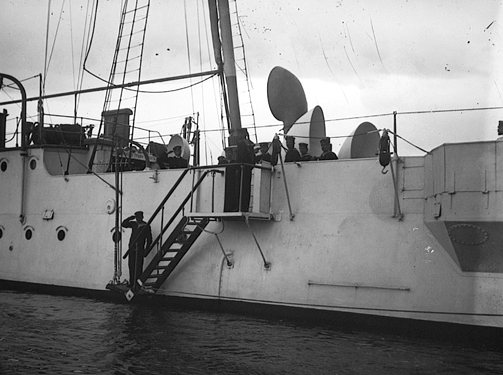
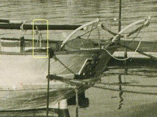
Hello friends, that's a very interesting discussion, so here's my two cents: Incidentally I have seen such a thing as a boom rest. Not in real life (as the ship burned down during WW2), but in several old photographs, one of which I attached here a crop. The ship was Romania's first Training ship, a brig called "Mircea" (I) and was built by Thames Iron Works and Shibuilding Company, Blackwall near London in 1882. Please see for yourself the boom rest in the attached photograph. Please note that this is on a 19th century ship and moreover, a composite one (that means wooden strakes over iron frames) so the support itself is also made of iron. My own understanding was that the support is not a permanent fitting there but it can be folded and either lie flat on the deck or be put away on stowage when not in use. One thing is certain, there's just one such thing and is right in the middle of the ship, not on a side! Hope this helps!
-
Why were/are masts and spars tapered?
Doreltomin replied to achuck49's topic in Nautical/Naval History
I would say the question is not just about weight. As Jud says, just think about the distribution of a force acting laterally on the mast. It acts just like one arm of a bow or more precisely like a cantilever with one end free and the other anchored securely on the deck. See: http://en.wikipedia.org/wiki/Cantilever Without goind too deep into structural analysis, the point is that the stress accumulates at the bottom of the mast, so the mast has to be thicker there to withstand the stress. If instead of being tapered, it would have been straight, that would mean it would surely break at the foot because the ratio between its strength and the forces applied to it would have been the worst at this point. Now think again of one arm of the Archer's bow: it is also tapered from the tip to the middle for the same reason: to have a constant ratio between its strength and the forces applied to it, otherwise any irregularity would mean it would surely break under stress. Hope this helps! -
@ Woodrat: re-reading my previous post it became obvious that my English has betrayed me. Actually what I wanted to point is that the difference between the Nao and the Carrack can be... minor to non-existent. A "Carrack" can be a certain ship loaded with soldiers and prepared for war, yet the same ship can be used primarily for transport while retaining her armament as a protection of her cargo. Practically the external appearance would be the same. Not to mention that in most Latinic languages "Nao" (Nave) means "ship" and hence applies to all ships regardless purpose. And yes I agree with you that the high bulwarks of these ships were somehow effective against the attack of pirates from a low galley. However, the galley was much faster and could move even against the wind. So the high bulwarks alone were not effective except if there were a lot of soldiers on the deck ready to fight the pirates. I am recently turned home after a week of vacation on the western coast of Greece on the Ionian Sea. Here I have visited a nice gulf called "Sarakiniko" which alludes in its name of the Sarrazine pirates which once raided the Mediterranean. There's not only one gulf called like this, there are many of them, which hints of how elusive these pirats were. They could do this despite the power of the Byzantine, Venitian or Genoese ships which guarded these seas because of their low, fast ships.
-
Hello Lukas, Congratulations, that's a very nice model indeed. Heller plastic kits can make into very interesting models, only you have to be patient and careful with them. It seems to me that you are not certainly a novice, it's a clear thing that you know what you are doing up there! I particularly like the colour of the deck. In the first pictures it looked a bit too gray, yet in the latter you added some lighter coloured strakes... is that all paint over plastic or you remade the deck in wood? Looks very authentic, anyway! This on the light side. Now on the dark side, it seems your masts are a bit curved, you must take your time to correct this. Either trying to straighten them (generally speaking I used a recipient filled with hot boiling water and a pair of pliers to make them straight, check first the correct temperature with a piece of plastic) or replace them in wood if you are not sure about straightening them in hot water. Keep up the good work,. have fun and cheers!
- 110 replies
-
- 1
-

-
- heller
- le superbe
- (and 2 more)
-
Hello Woodrat, It's good to see you started again this project, this time as a full model. Looks good so far, keep up the good work! I also like the colour of the bulwark. Insofar I know, the wood outside the water was treated with a compound which, if I am right, in Italian, Provencal and Catalan, otherwise said the north-mediterranean languages is called "harpuse" and includes resin from conifer trees, therefore giving the wood a pleasant yellow-reddish colour. One more word regarding the name.It is not taken from anywhere else instead it is my own thinking as I have always loved to link words from different cultures and search for their primary meaning. So please judge this with your own mind and conclude for yourself if my theory is misleading or not. So.... The name Carrack may sound confusing, although it is the same in all European languages. It is Carrack in English, Carraca in Italian, Kraeck in the famous engraving of the Flemish Master William Croce. I have seen Nenad's comment up there and it is the same in Croatian as well. It is confusing for us Europeans because actually this name comes from Syriac, a language of the Close East. If you have ever heard of he "Krak des Chevaliers", originally known as "Krak de L'Hospital" (search for the link on Wikipedia) then you are close to the original name of the ship. "Krak" in Syriac originally meant "fortified castle" and the name was later borrowed for naval use, where a "Carrack" was a fortified ship suitable for war, otherwise said, a warship. Therefore a Carrack can well practically have the same lines as a large "Nao" yet what makes the difference is her main purpose, the Nao being primarily a merchant vessel while the Carrack was meant primarily for war.
-
The pirate who is buried in a church
Doreltomin replied to marktime's topic in Nautical/Naval History
Thank you for the interesting story! However, as the previous posts said, the skull and bones are a sign associated with piracy only in our times. Back in the middle ages this was a common sign for tombstones. I remember seeing the same sign on many tombstones in the Cathedral of Barcelona. I mean the 14th century building dedicated to Saint Eulalia, not to be confused with Antoni Gaudi's Sagrada Familia. -
Aaah, Nigel, you were faster than me! I was just trying to write here about the same thing when the site said "there are two more answers to show".... if she's not the HMS Glatton then she must be one of the Cyclops class of 1870: HMS Cyclops, HMS Gorgon, HMS Hecate, HMS Hydra. Later edit: With the last clue "name the same as her class" that makes: HMS Cyclops! So congratulations Nigel, seems you got her!
-
Michiel, There is no "safe rule" regarding guns as they come in very different sizes and makes and it was common practice to re-use guns, but insofar I know there is an "older' fashion of about 1600-1720 where they have cast handles and a "newer" fashion after 1720 when they don't have handles anymore. Actually these handles are somehow superfluous: if they are too thin they can broke if the piece is lifted from them. If they are too thick they add to the weight of the piece; anyway, the piece can be lifted with the rope twisted from under it. Also in the meantime they have gained experience and knew how to cast large iron pieces so it is more likely that the "new style" iron pieces don't have handles while the "older" pieces in bronze have them. As a rule of thumb it would be that smaller, older pieces like stone throwers were cast in bronze and had handles. Bigger pieces were cast in iron and hadn't. It is actually very confusing as there were surely new ships of around, say, 1750 which may have carried older cast pieces, these generally being the guns of smaller caliber. Hope this helps!
-
Hello Tomhard, while I can't be specific for the Riva kit which I don't know, generally speaking the first layer of planking is always GLUED to the bulkheads, while the second is surely glued to the first; the best glue is always white/yellow (PVA) glue. Therefore the nails are only used to keep the plank in place until the glue sets up, after which they are surely removed. Otherwise, you will have trouble sanding the hull between the nails firstly, not even to mention gluing the second layer over the first. Of course it is just your decision to use or not to use the nails. For instance in my builds I don't use nails to keep the planks in place until the glue sets, yet sometimes I find useful to use some sewing pins. I have also seen some people here using several other techniques like rubber bands (which are good for plastic models, yet sometimes don't have enough strength for wooden kits). Then you can also use some specially designed devices, which are basically divided into two main categories: Some look like heavy clamps which clamp on the bulkhead... but these are mostly useful for the first layer of planks. Other look a bit like a sturdy pushpin with a plastic tongue to keep the plank in place, which is of course only pushed into the thickness of the bulkhead, not in the first layer of planks. If you do a quick search on this forum you will find much more information on how to do the planking! Hope this helps...
-
Hello Kutay, very nice model. Very interesting, the shape of this boat looks exactly like the typical fishermen boats here in Constantza; also I have seen the same type of boats in Bulgaria in fishermen harbours like Sozopol or Nesebar. May be kind of a "blueprint" of a typical Black Sea boat! Do not worry too much with your planking abilities. If the ship will be finally sanded smooth and painted, the irregular planks will not show. I have seen real boats where the planking had the same kind of irregularities, especially if an old rotten plank was later replaced with newer ones. Sometimes they would not replace all the plank, only cut away the rotten part and replace with a new piece. I also suggest you NOT to use any Cianoacrylate in planking, only wood glue like PVA glue. See here: http://en.wikipedia.org/wiki/Polyvinyl_acetate Wish you good luck with your building and best wishes from Kustendje!
-
Hello Old Salt, yes, that's the rule.. who guesses the last one posts the next! So please post the next mystery photo, but make sure there are no obvious hints left like the name displayed proudly on the bulwark, on the photo or even in the file name!
-
Edge bending planks
Doreltomin replied to ortho85's topic in Building, Framing, Planking and plating a ships hull and deck
Hello, I'm here with the gentlemen above: Don't fight with wood! All you have to do is taking a wider plank which you will then trim to make look like curved. I believe for practical reasons is always better to use in our models pre-shaped pieces which have no internal tension trying to reverse to some previous "flat" state. Of course you will need a wood with small grain which will not show the trick. As a disclaimer, haven't tried that myself, yet for practical reasons when doing planking, instead of using curved wood which comes up very poorly, I generally use 1 mm plywood from which I cut curved "planks". The curve is generally taken with a paper jig, so the finished piece is made to fit perfectly to its place without any need of edgeside bending. -
ROYAL CAROLINE 1749 by Doris - 1:40 - CARD
Doreltomin replied to DORIS's topic in - Build logs for subjects built 1501 - 1750
Hello folks. today I will teach you how to make gun barrels. You first need a $1600 lathe and then.... no, no, no, just take some paper and... Thank you for your lesson, MASTER Doris!- 883 replies
-
- 6
-
-
- royal caroline
- ship of the line
- (and 1 more)
-
Excellent work, thank you for re-posting your log, I truly love how you managed to do it! Congratulations!
-
Hello Vivian, have fun on this one! I also think the same as Mark above, you are slowly and surely approaching "the dark side" Best wishes, this will be a nice build!
-
casting metal parts including cannon
Doreltomin replied to rtropp's topic in Metal Work, Soldering and Metal Fittings
Thank you Joe, that will be a thing which I will surely follow with utmost interest! Meanwhile, thank you very much Chuch for your photos, they speak for themselves. As the saying puts it, a good photo worths more than a thousand words! -
Hello Alzarius, you should take it like that, until now you just practiced planking. I am bit surprised of the dark colour of your first planking, I have expected to be something more flexible and less expensive wood like fir, which is a lighter wood. I am sorry but I am not in position to suggest you a wood supply in the States as I am from Europe and have little knowledge on what you can get there. However you should try some hobby stores near you, I am sure they have wood in various sizes among other things. But for the first layer you should look for the cheapest type of wood, not of cheapest quality as you need to be of regular grain and free of knots and irregularities to bend correctly. Also looking at your planking attempt it seems to me that it goes that way because you tried to put the planks straight from the box. You should have considered a little tapering of each plank at the rounded part of the hull to make them go well one near the other. Also if the rounding of the hull is extreme you should fill up the whole with some inexpensive soft wood like balsa which you later cut and sand to proper shape. If planking causes you headaches you can even fill your hull completely. Balsa is a very light wood so the model wouldn't be very heavy if filled up. Remember, the first layer is the one which does the shape and actually can be done with anything, including strips of thick paper if you want it! Just take a look here on the MSW: there are some folks which build their hulls of PAPER. Yes, check "paper models" and you will see how they do their hulls using strips of paper put first transversally, then longitudinally, all properly filled and sanded until the shape of the ship looks perfect. There's even somebody .... see him here: http://modelshipworld.com/index.php?/topic/1420-papegojan-by-mati-148-dutch-pinnace-1627/?hl=papegojan which did his ship in paper then dressed it in wood, and now it looks as if a wooden model, yet the core is.. paper! And one more word: it seems to me that you use CA glue, which is Cyano-acrilate or "super glue?" I would use PVA glue or "wood glue" instead! Good luck with your build, and remember.. there's no good or bad modellers.. only experienced and less experienced, and nobody has ever build its experience except if "hands-on" by doing many mistakes at the beginning!
-
By the way, I am not so sure if mahogany is a good choice for the second layer,even if your kit used this. As I have pointed previously, the trick is to find a wood which has the proper grain of oak reduced to scale. You cannot use oak to simulate oak reduced in scale, because the grain will look too coarse. You need something with finer grain. The best fit for this are fruit trees: plum, apple, pear, perhaps lemon. My favourite is plum, which grows into two different colours, one is darker and may be used for hull, the other is lighter and can be used for deck planks.
-
Hello, just as Rich said, the first layer is made of unexpensive but thicker planks just to make the required shape. If incidentally your building skills are not at their best, at least you can correct the shape using either sanding for the bulging parts of filler for the hollow parts. You can even add some wooden blocks and cut them to correct shape if this better suits your needs. The only important thing is that you get a correct symmetrical shape of the hull as seen in the plans. You may check the shape by the rake of the eye or even use some templates made of cardboard to check the proper shape where your eye says things are not all right. Once this is done, you use the second layer which is only "cosmetical"; it's purpose is just to make the hull show as if done from wooden planks. Sometimes it is as thin as just 1 mm thick and is made from veneer instead of planks. Here if you sand a bit more you will get a hole in the plank so you will need to sand with caution, but the purpose of the plank being so thin is to perfectly adhere to the correct shape which you made previously. Another trick is that the first layer is made of inexpensive wood, mostly fir or something like that, the second layer is made of expensive wood chosen to look as if oak (which was the wood generally used for shipbuilding) reduced to scale. Of course this does not apply to hulls which are to be painted, where the wood grain does not show, being already covered by a layer of paint. Hope this helps!
