Der Alte Rentner
-
Posts
1,018 -
Joined
-
Last visited
Content Type
Profiles
Forums
Gallery
Events
Everything posted by Der Alte Rentner
-
 Tom, I hope you’ll pardon my trip to your shipyard via Way-Back Machine, but since I’m starting work on the fighting tops, I’m looking at build logs to help fill in the gaps in my plans and experience. The plans (page 6) show that the top platforms are 1/32” thick. And a note below the drawings of the three tops says, “This (sic) is fore and aft planking on real ship.” You said above, if I’m not misreading, that you planked the top and bottom of the platform, with 1/32” stock. Furthermore, you said you used 1/16” wood for the edge and side pieces. My math suggests that the thickness of the tops add up to 3/32”, which is thicker than the side and edge pieces. Did you only plank the top’s tops? Bottoms? Did you use wider material for the sides and edges? Or did you sand a 64th off of the top and bottom of the fightings top after planking? (and Jon, if you’re following along, I KNOW you recently supplied me with the official plans showing the planking, but for the life of me, I can’t find that post. Please steer me in the right direction. Thanks) Best, Peter
 -
Two down. That's the lot. (my apologies to those who have already seen and reacted to this post, but before I added this last photo.)

-
I would be curious to know if the original Sphinx had mitered corners. I suspect they would have been problematic. Does anyone have photos of the original anywhere? As far as the model is concerned, I think a mitered corner would be absolute perfection. However, as I am constantly being reminded by others, no one is going to look that closely. And judging from what I've seen on other models at model ship world, the butt joint seems to be in the majority. Done well, both work. Done poorly, reach for the paint can? 😆
-
It seems academic to me. If you wish for the gun barrel to be centered between the upper and lower gunport frame member, you can use whatever thickness material you care to for the frame, and calculate the thickness of the spacer you use to position it accordingly. No? Am I over thinking this?🤔
-
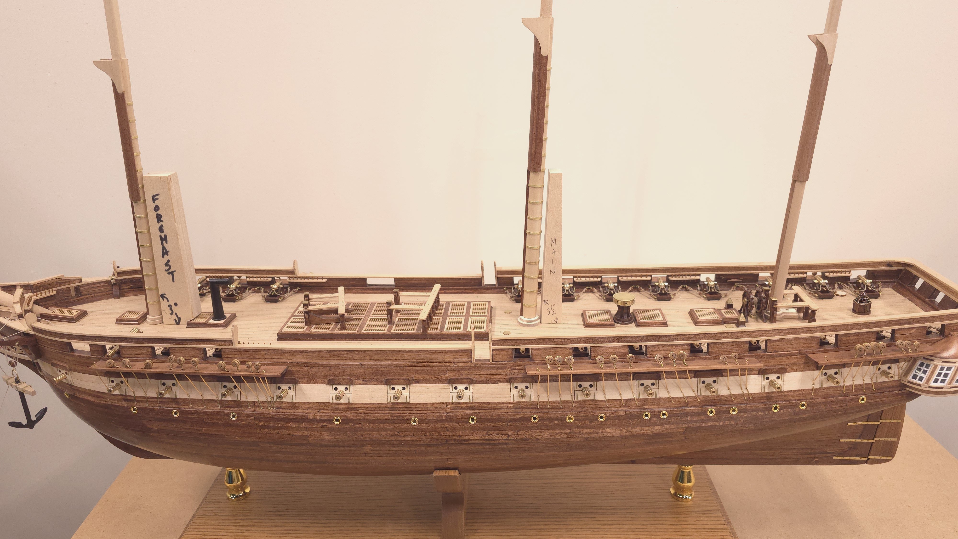
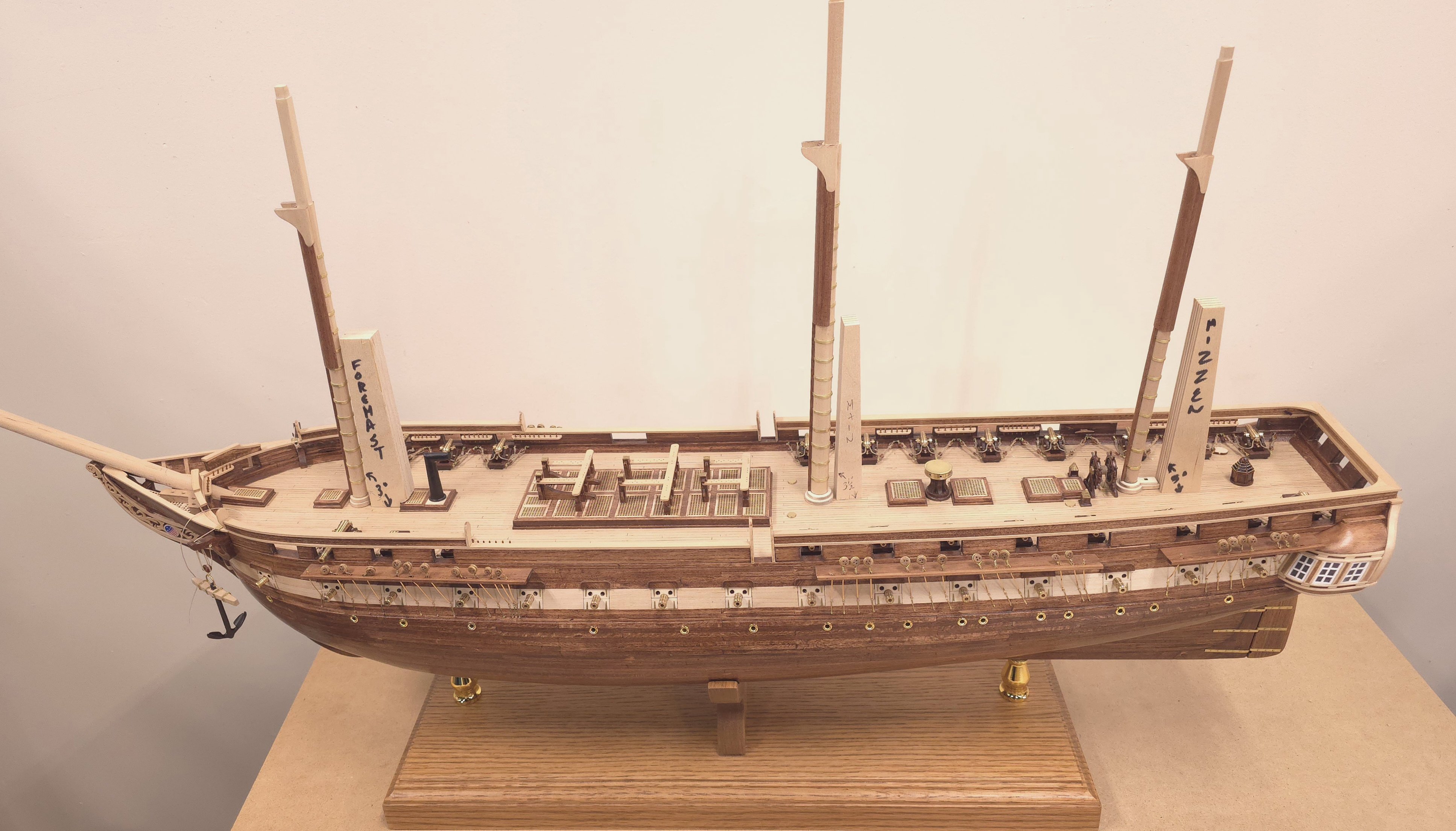
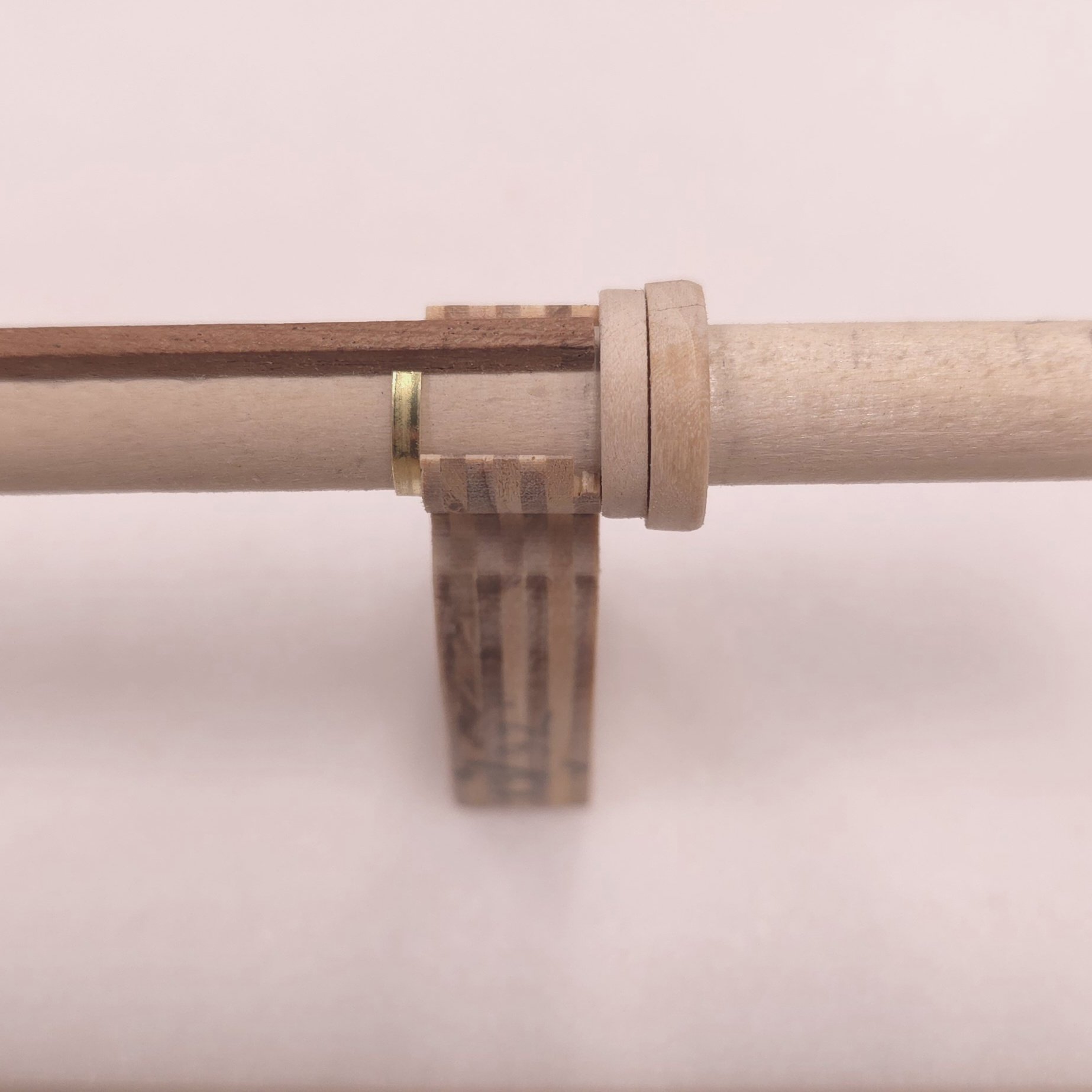
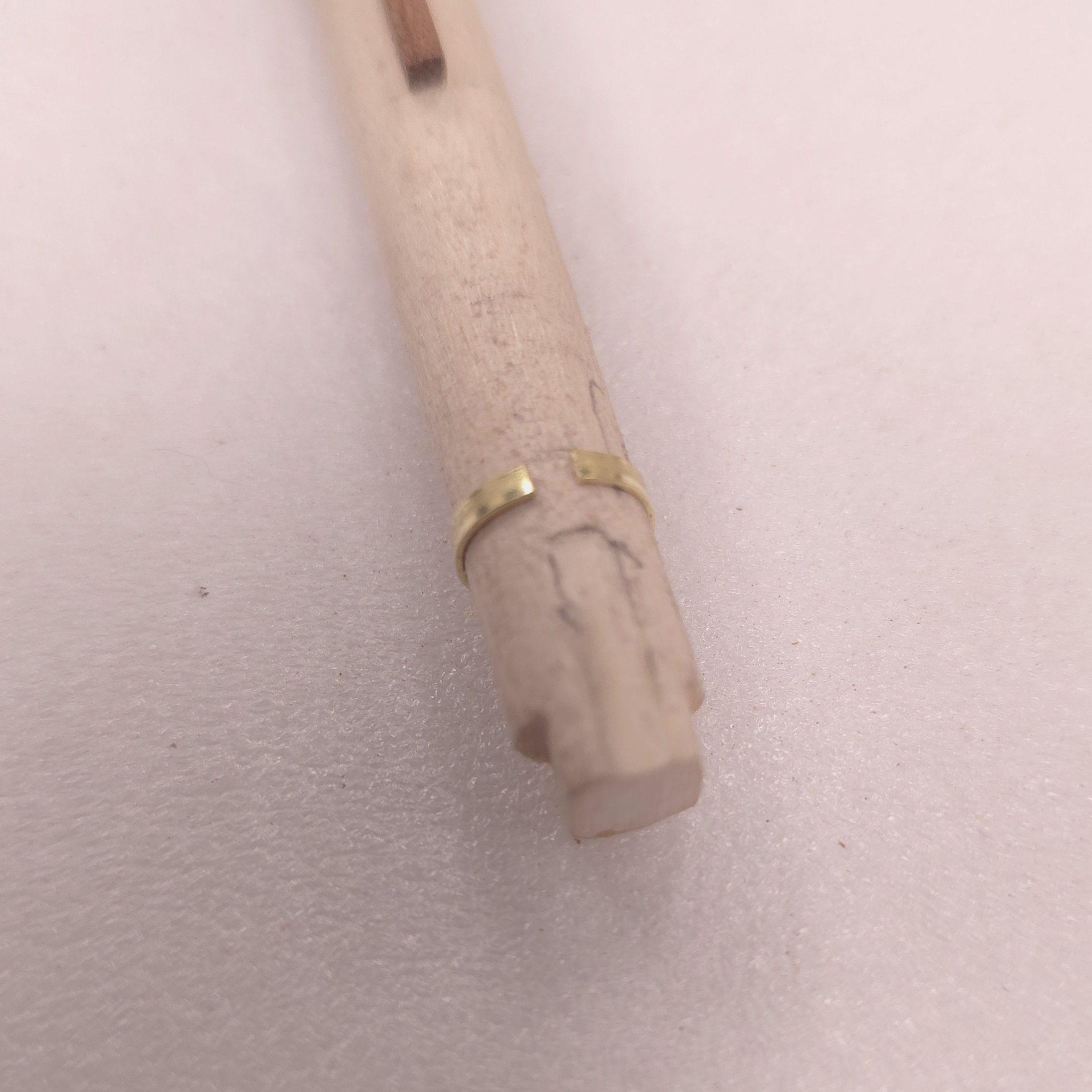
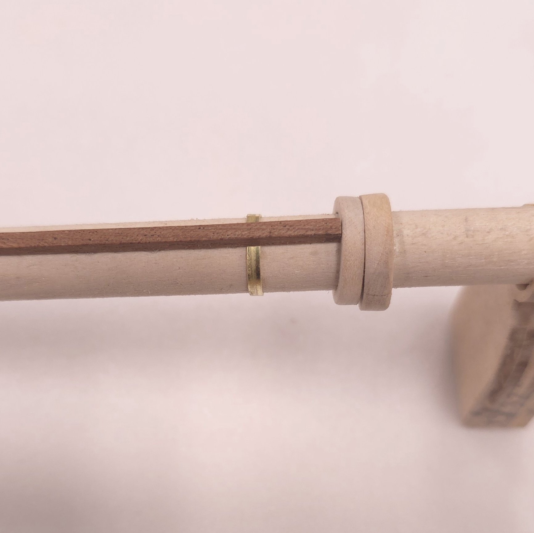
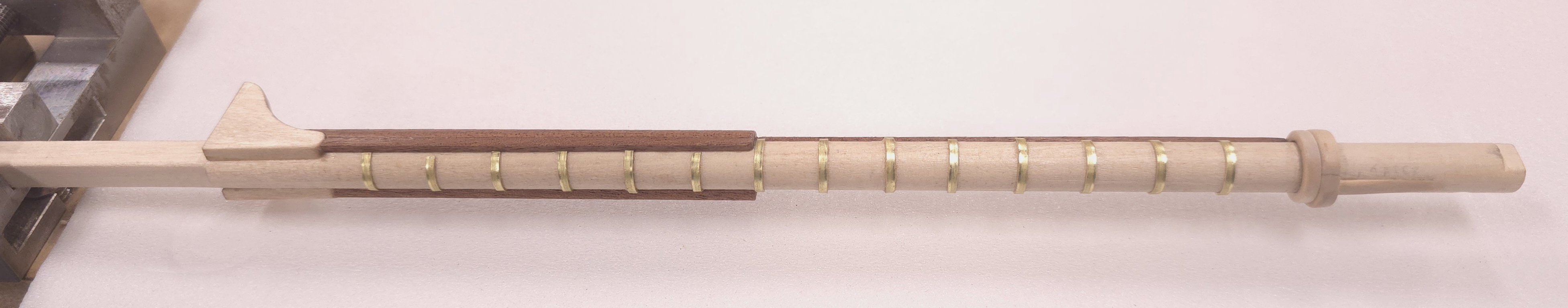
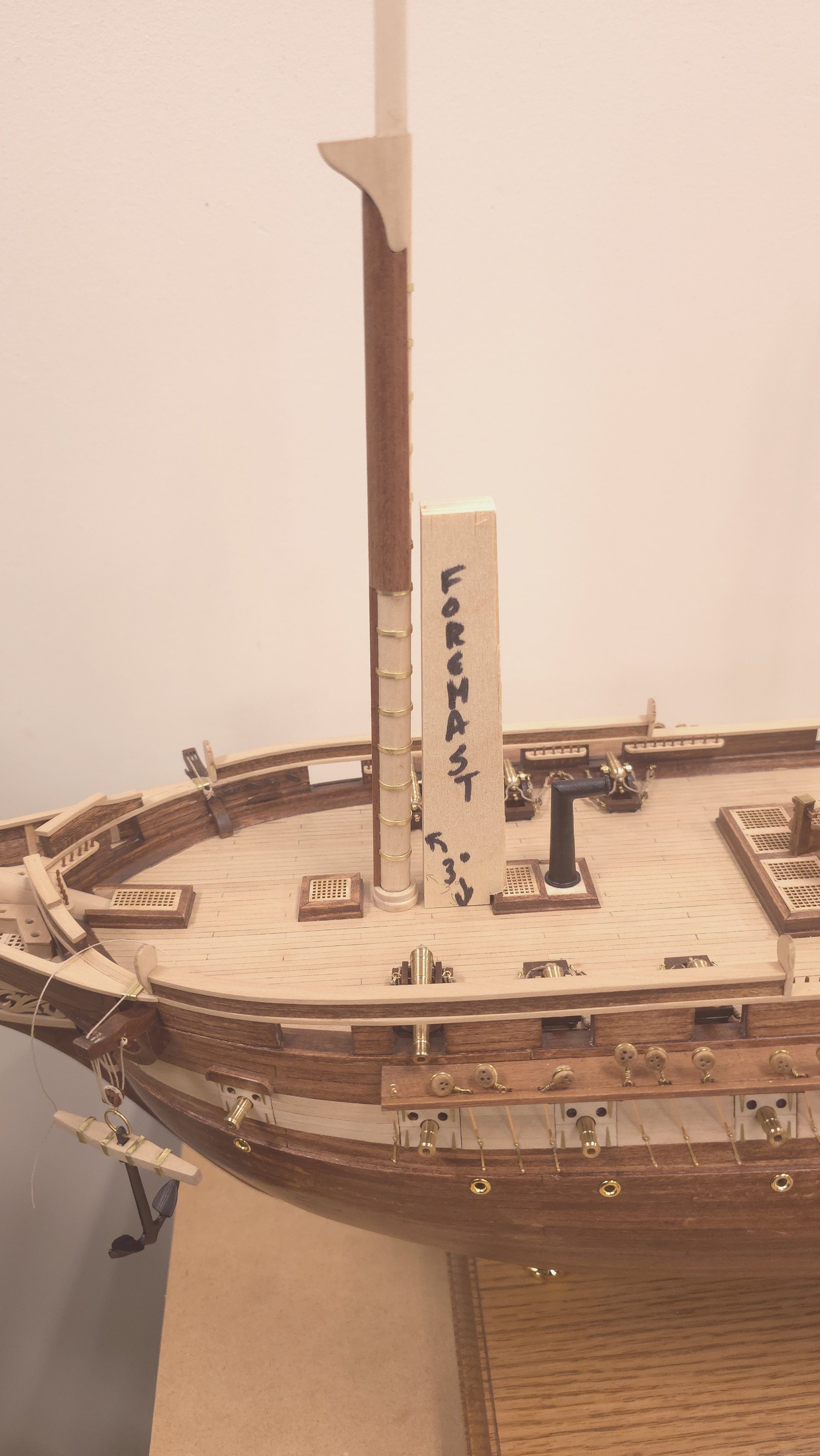
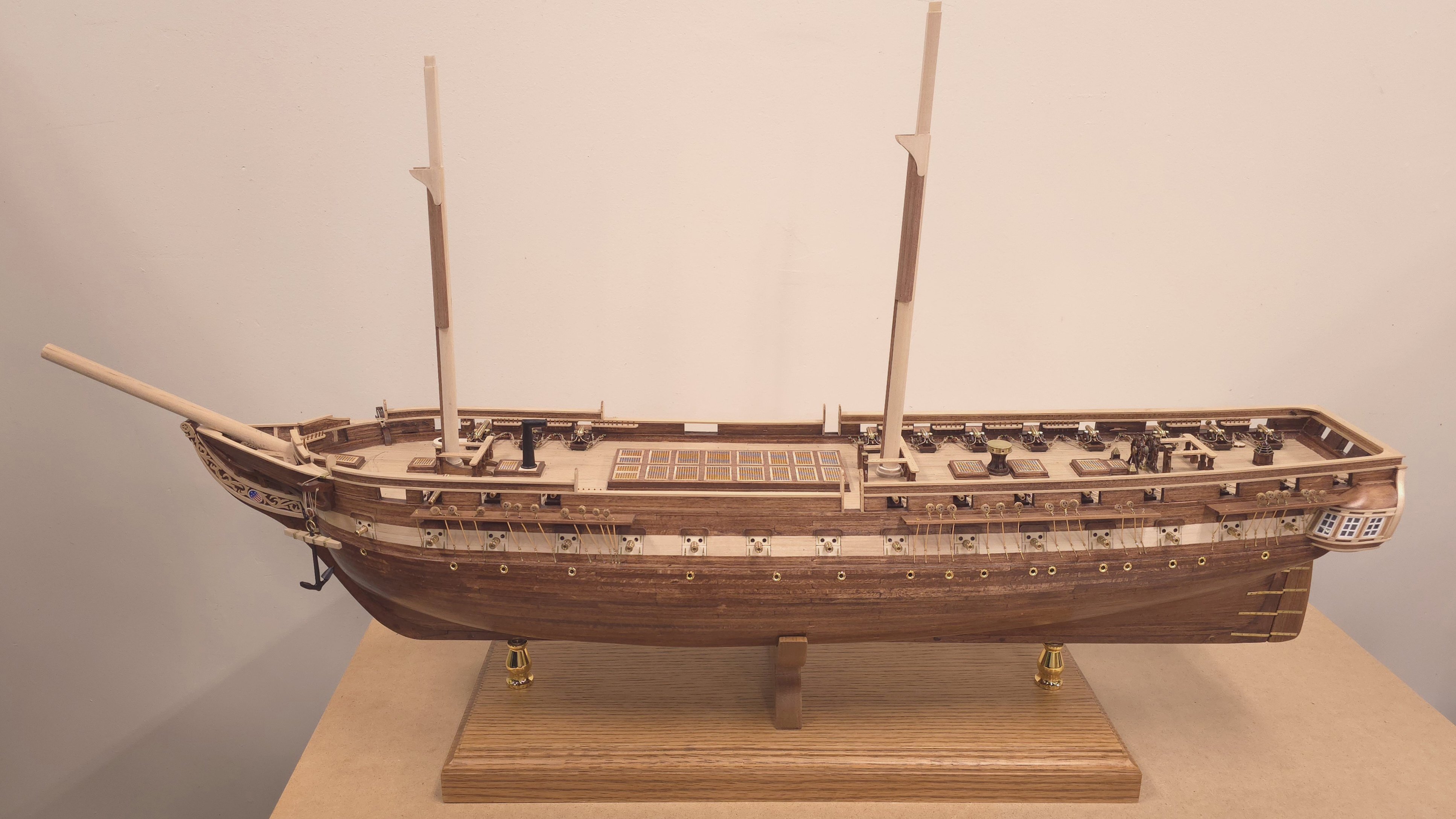
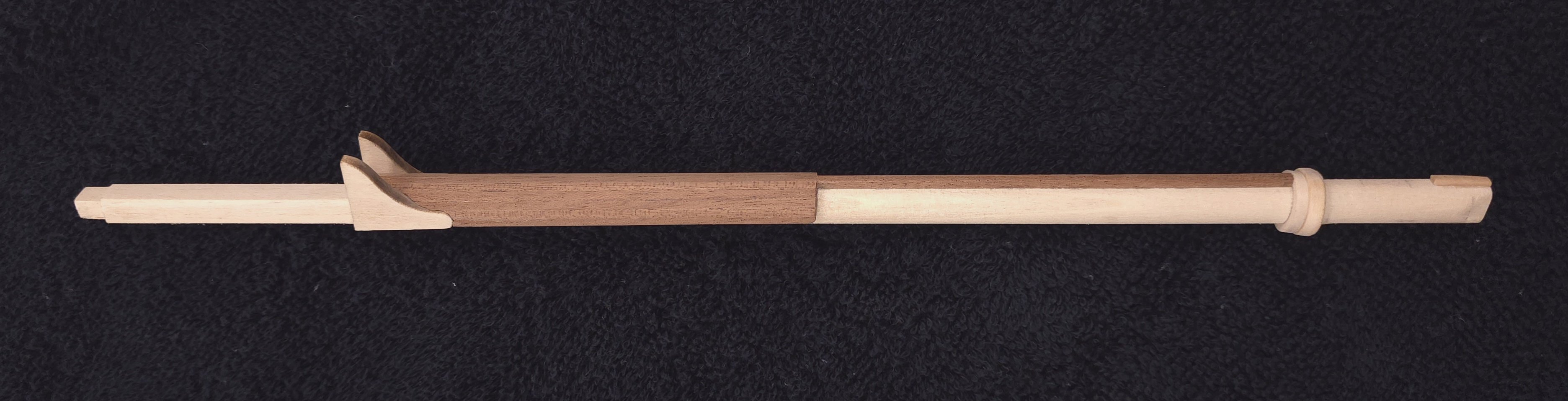
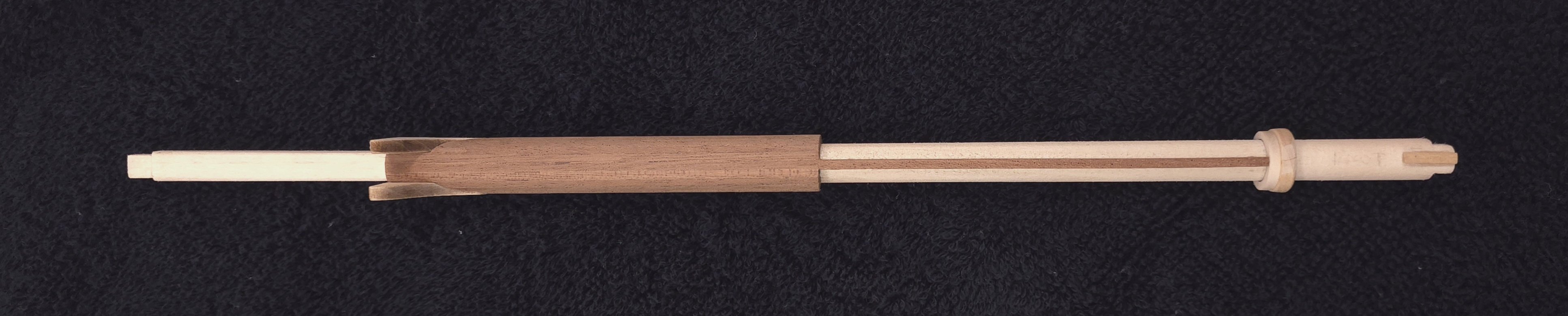
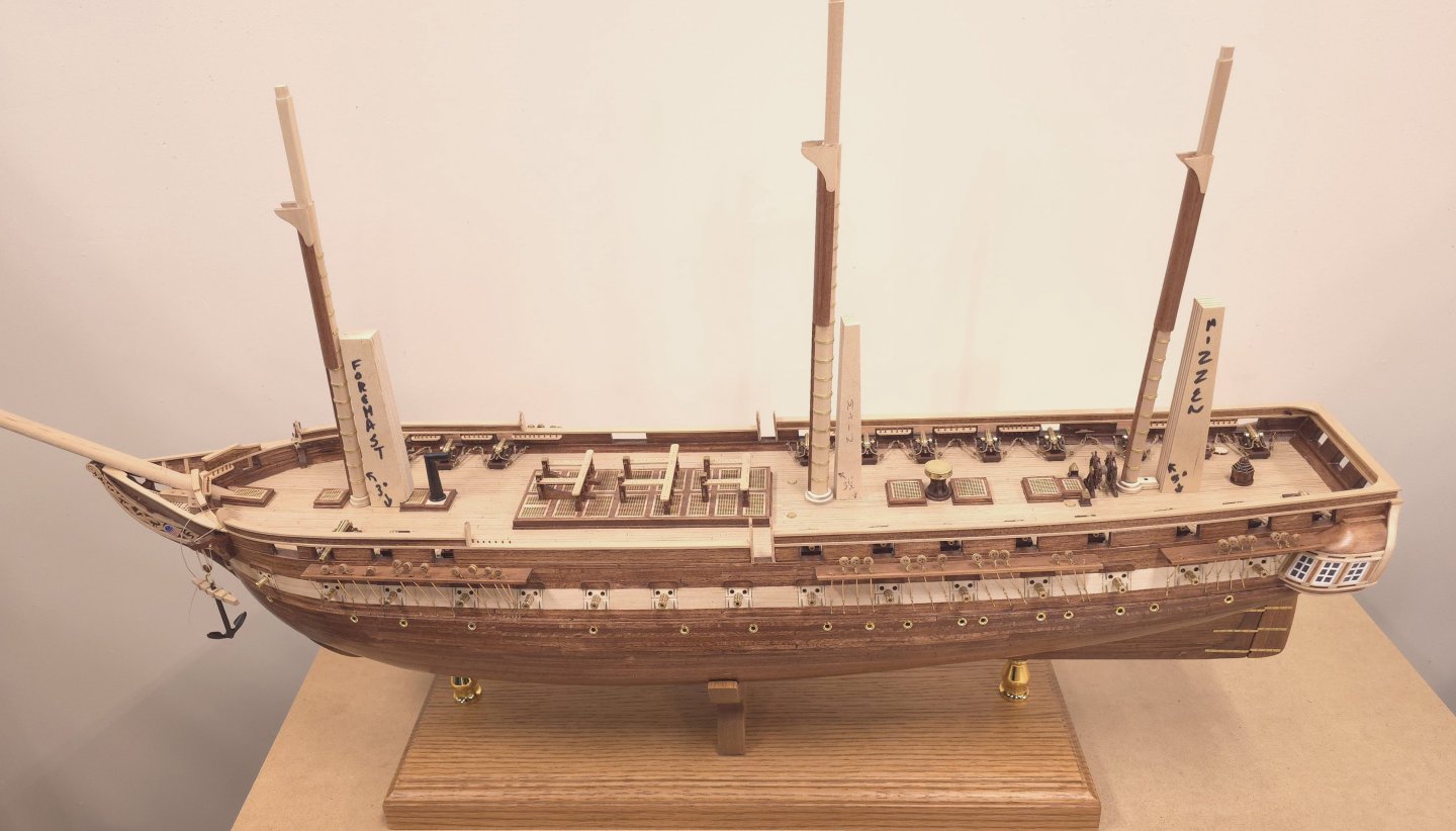
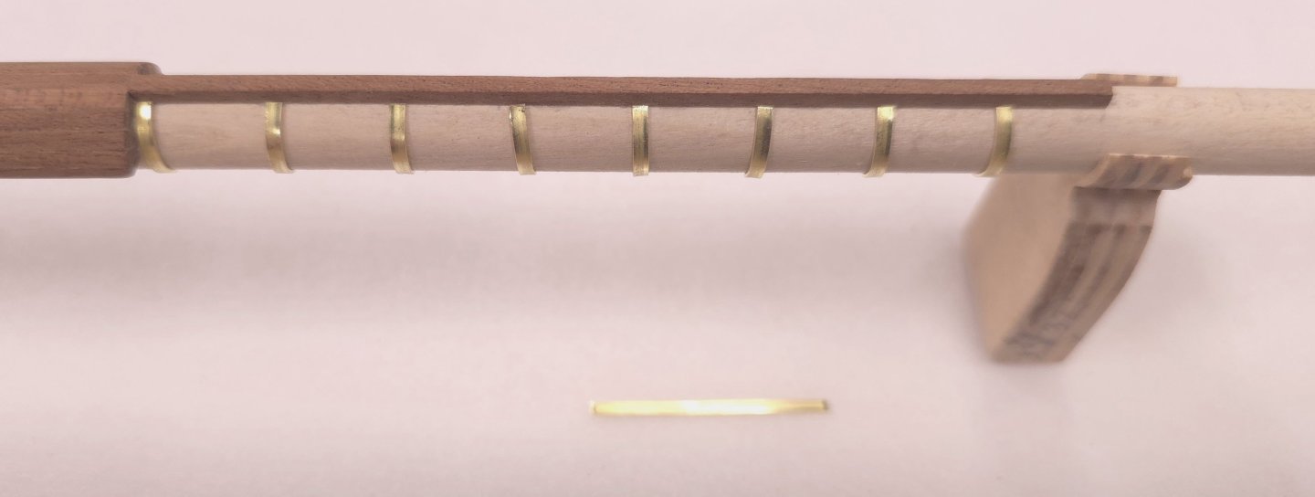
Turning my attention back to the fore mast, it was time to tackle the mast bands. I had some spacers at the bottom of the mast so that it would sit properly at three degrees to the spar deck, but to get the formed bands slid up the length of the mast, I had to remove those and replace them afterwards. The brass material that came with the kit - 1/64" thick by 1/16" wide, held its shape quite nicely after wrapping it around the mast. So, I didn't have to go through gymnastics to get the bands made. I calculated the length of the brass strip for each of the two locations where these would be installed - at the bottom of the mast, and between the chafing fish at the top of the mast. After cutting the pieces to length, I bent them around a dowel of the same diameter as the mast, trimming with a belt sander and file as required to get a good fit. I did make a jig to help space the bands along the mast. I actually made the band spacer before I went into production on the bands, after I remembered that I couldn't slide the bands onto the mast with the wedges at the bottom. Just explaining why the picture below left shows the wedges.. I added back the wedges, applied a coat of poly, posted this log, and am now heading home. At the current rate of production, it'll be two more full days before I finish the main and mizzen masts.


-
USS Constitution by mtbediz - 1:76
Der Alte Rentner replied to mtbediz's topic in - Build logs for subjects built 1751 - 1800
Me too! 😎👍 -
I think you're going to have to take a much closer photograph of the problem area for me to be able to see what it is that bothers you so. In the photo above, even zoomed in as far as I can, I don't see the end grain issue you're concerned about. But guessing that you don't have a miter joint there, I'm going to assume the kit didn't give you enough extra laser-cut trim to be able make a corner wedge to hide the end grain. As a bit of a perfectionist struggling with natural finish issues myself - as opposed to painting over flaws, I completely understand your desire to achieve the look you want. I guess you'll be making new trim strips from scratch. Looking forward to seeing the results. Best of luck in that endeavor.
-
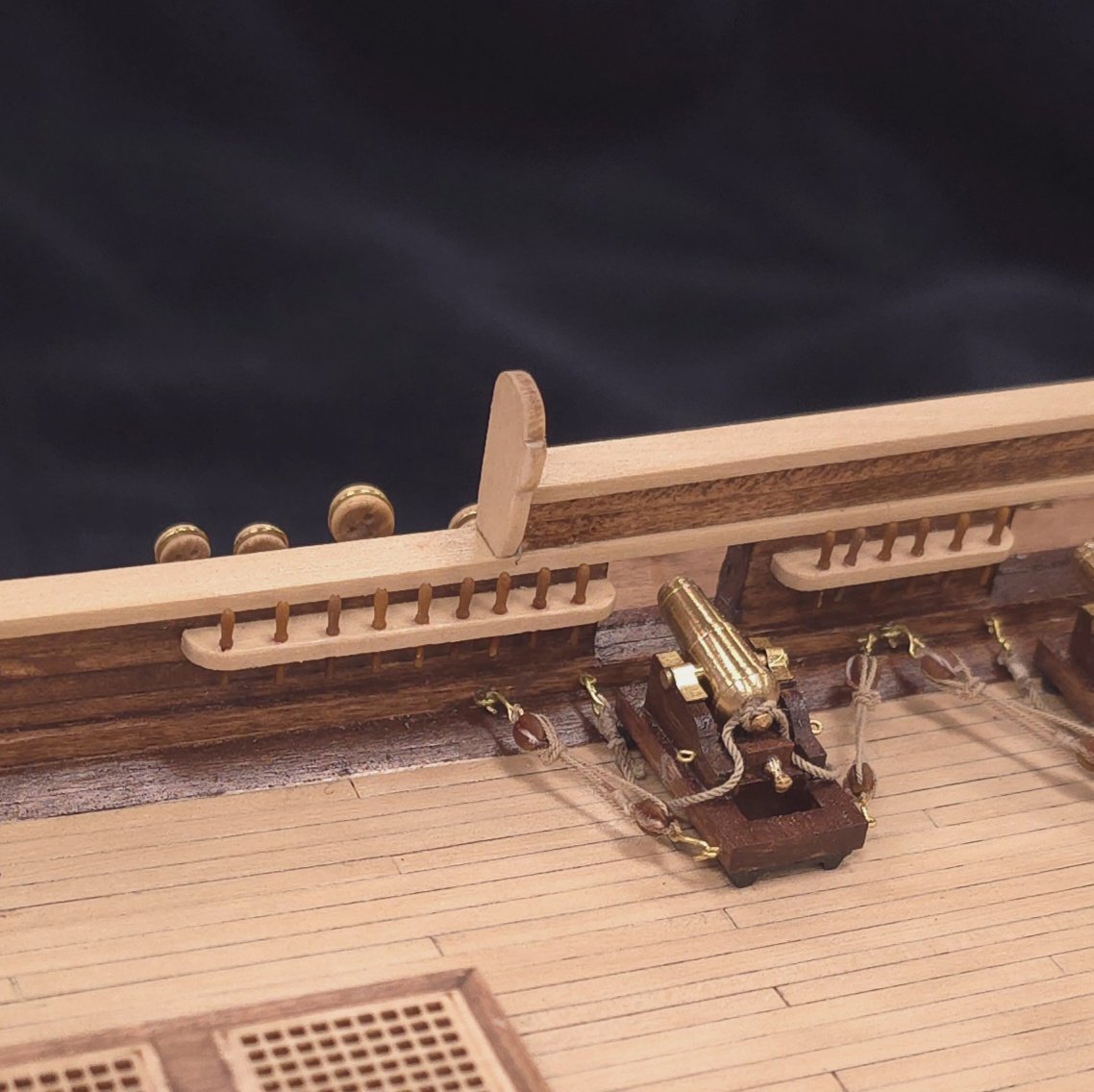
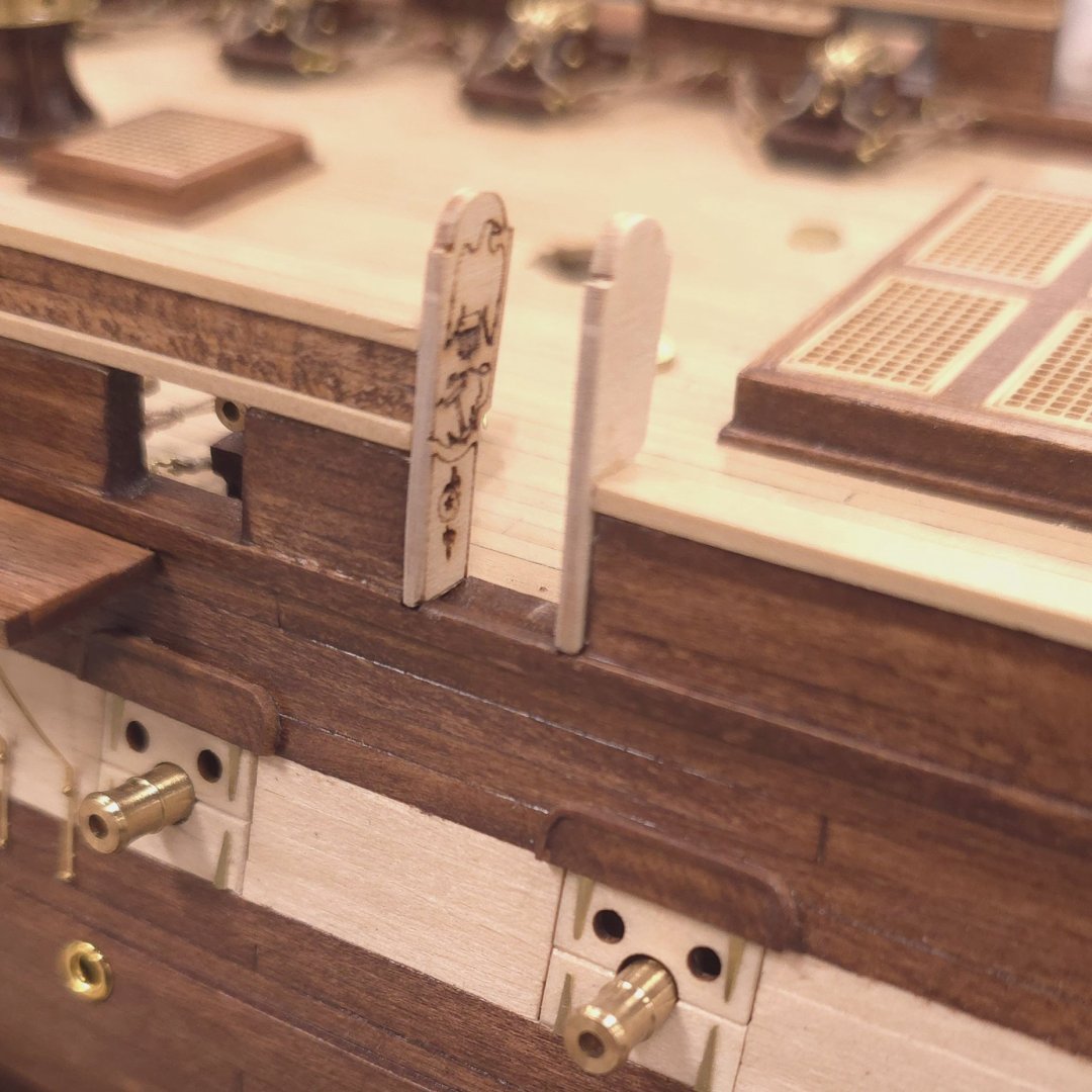
Thanks for the heads up, mustafa. I'm not worried because the Fife rails are not yet glued down. I was waiting for the right time to do so. Before I do, I'll make sure they are where they belong, as well as the eyebolts on the deck. I just staged the Fife rails for the photo. Thanks again
-
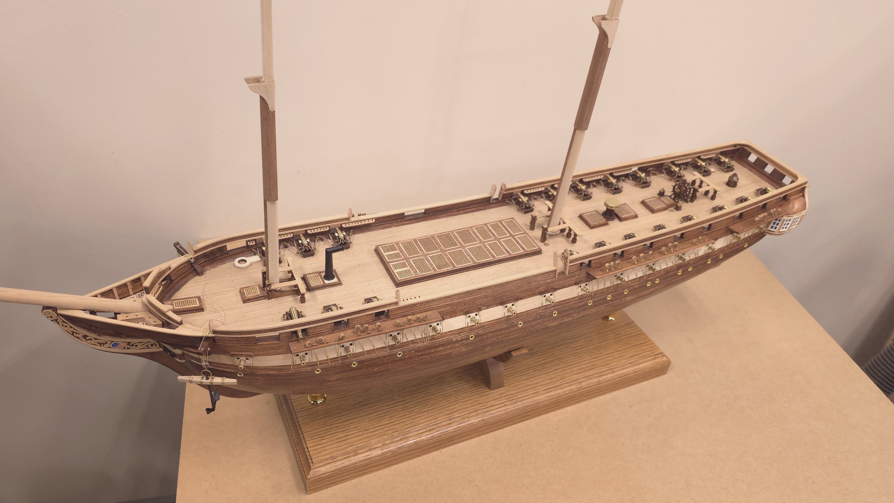
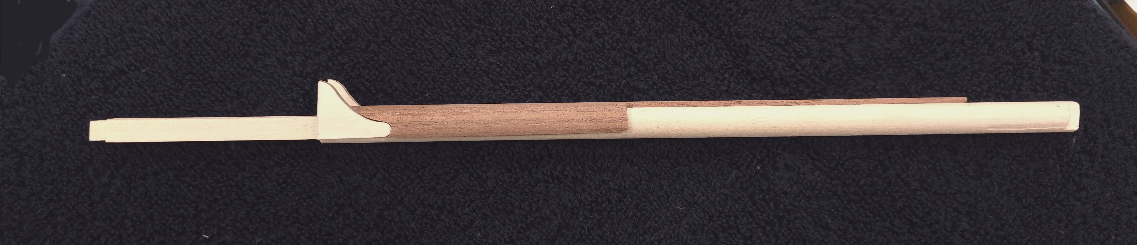
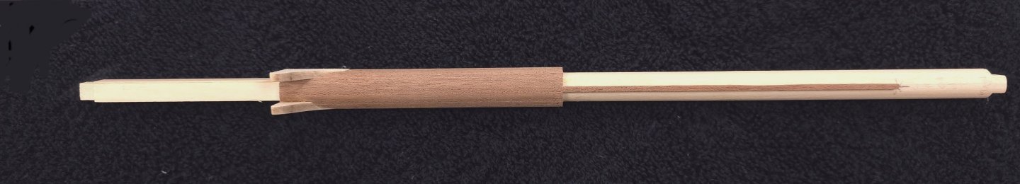
At last! Chafing fish adorn all three masts. I'm not quite ready to move on to what Gregg calls the fun stuff 😆. I still have to do the mast bands, the fighting tops and the bowsprit. Then the hilarity should ensue.

-
Are you sure about that being the fun stuff? 😁
-
Hi Gregg, Just checking in to see how the build goes, and would have left things alone with the "like" a couple of posts back, but noticed the new profile photo and had to comment. Very nice. Enjoy your papa week.
-
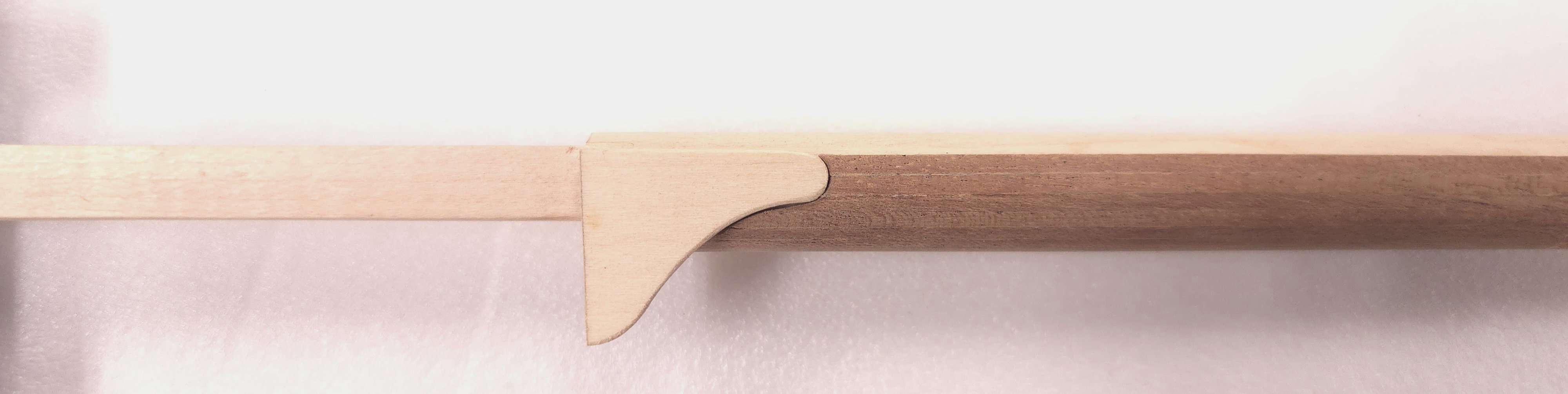
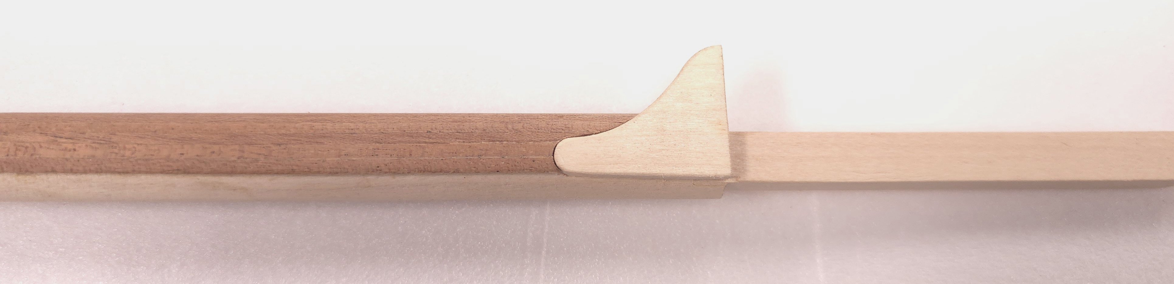
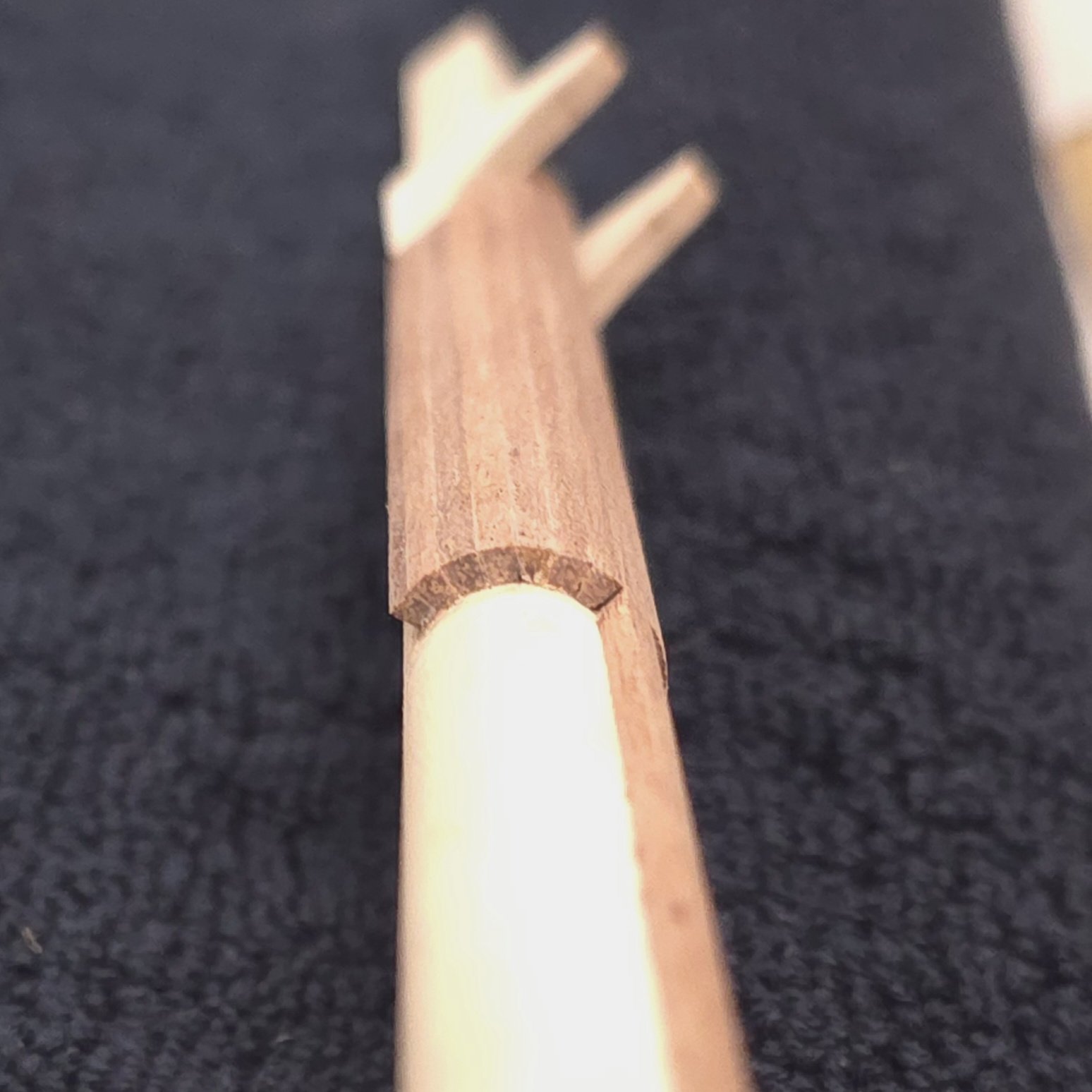
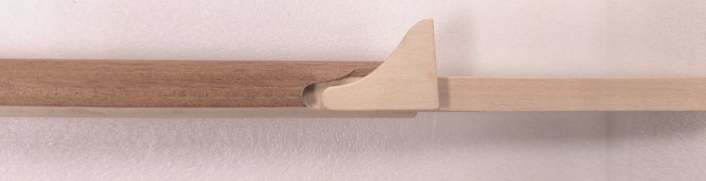
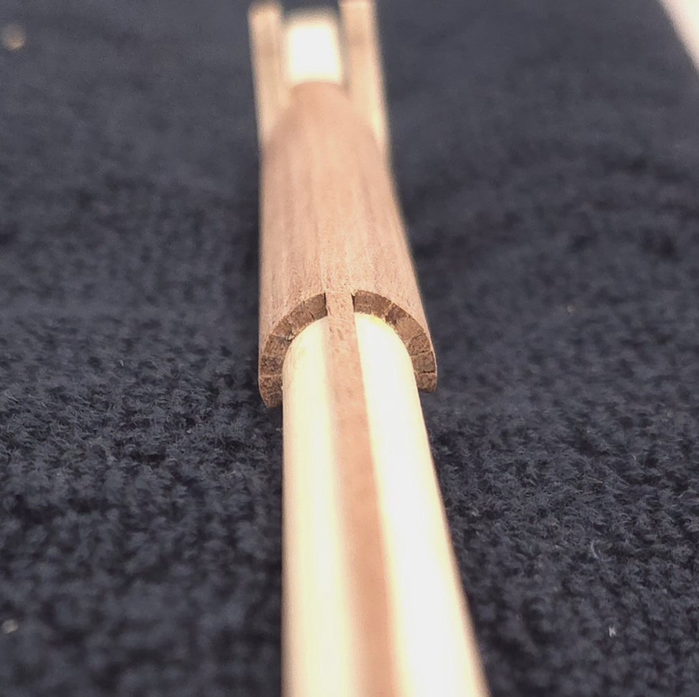
The hardest part is carving out the indentations for the mast cheeks. Two down. One to go..


-
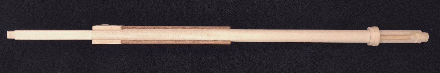
There wasn't enough of the 2 mm square stock supplied by Constructo to be able to complete the remaining two masts. So, this morning I used some of the ample 2x6 mm sapele stock they provided and made my own 2 mm square strips. Also, while my jig did produce a decently chamferred product, I wanted a quicker process to chamfer an entire strip. So, I rigged my belt sander to accomplish the task. This worked surprisingly well, or so I thought.. Readying the bandsaw to cut 2mm strips. Pass 1 Pass 2 Sander setup Chamferring done in two passes. Two steps forward, one step back? This looked promising, but the second pass yielded inconsistent results, causing me to consider pulling these last two photos. I couldn't keep enough downward pressure on the sapele to get an even bevel on both sides on the sander. It did a nice job for one side, so I only needed one pass with the hand plane and jig. I'll take that as a win. After beveling one side on an entire strip, I cut the material to length, clamped it into the jig and chamfered the second side by hand. This netted very nice fits. The admiralty is calling me back to home base. More next week..


-
Another 5 hours at the Shipyard to finish the chafing fish on the fore mast.


-
USS Constitution by mtbediz - 1:76
Der Alte Rentner replied to mtbediz's topic in - Build logs for subjects built 1751 - 1800
I agree with Jon on both points. And I'm so happy to see that so much of this was made easier by the Proxxon mill and accessories. Looking forward to following in your footsteps. 😁 -
Thank you Mustafa, and to all of you who have commented and reacted to my posts. Your feedback and support are invaluable to me. Here I thought that, once I got to the masts, things would move along quickly. Not so. 5 hours at the shipyard today, and I still don't have the chafing fish on the first mast done. Of course, part of that is due to a 'two steps forward, one step back' scenario. I glued the long central strip onto the mast - only to discover afterward that I forgot to taper it, which meant it needed to be milled off and remade. Trimming each piece of the chafing fish to fit the mast cheeks is quite time consuming. I'm happy to have the Proxxon for this task, and can't imagine trying to do this with small hand tools. The two remaining slats required on this side won't need much tweaking, but then I'll have to deal with 6 more on the flip side. And of course two more masts..


-
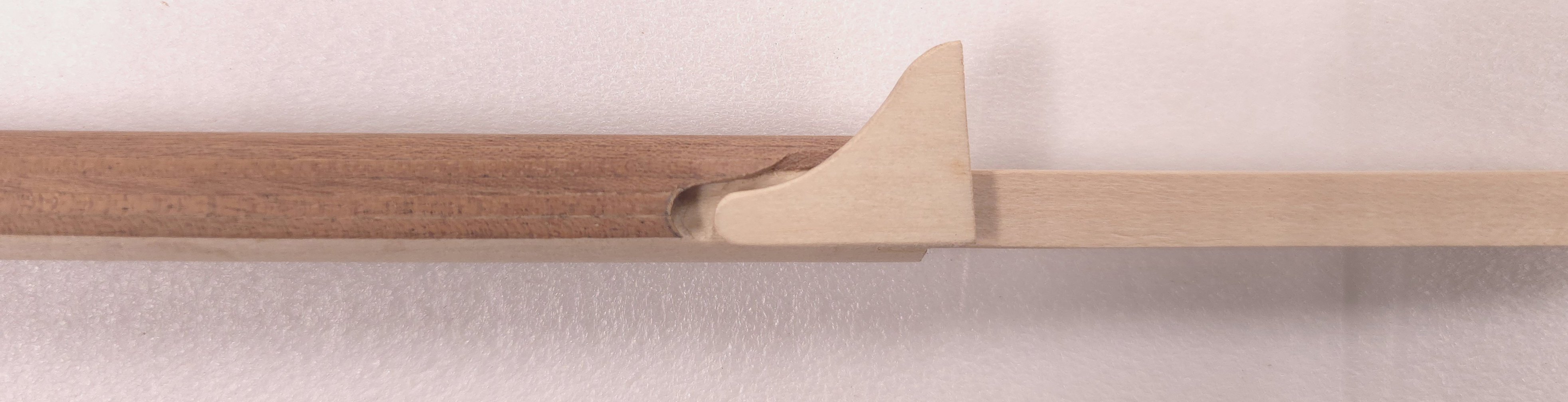
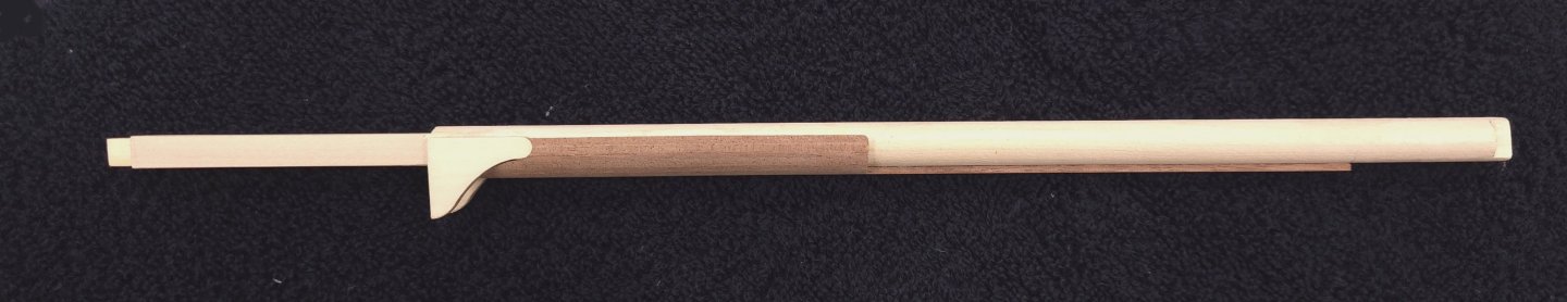
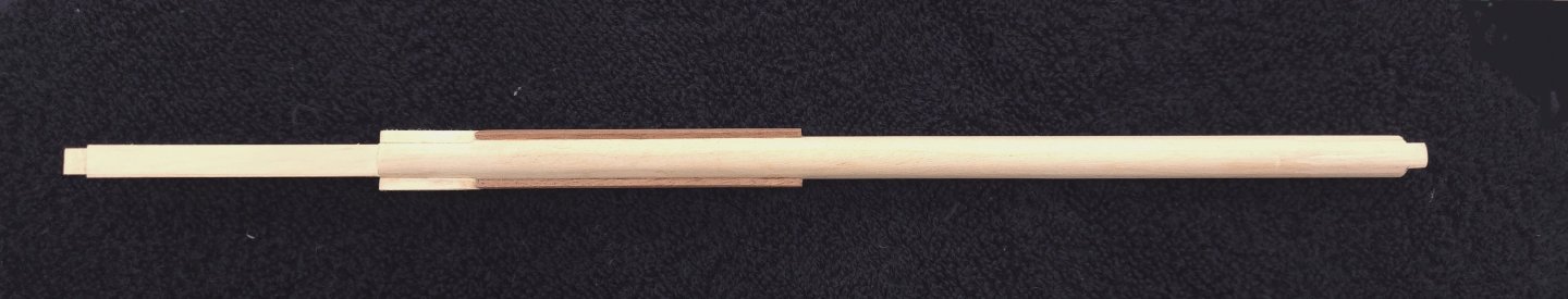
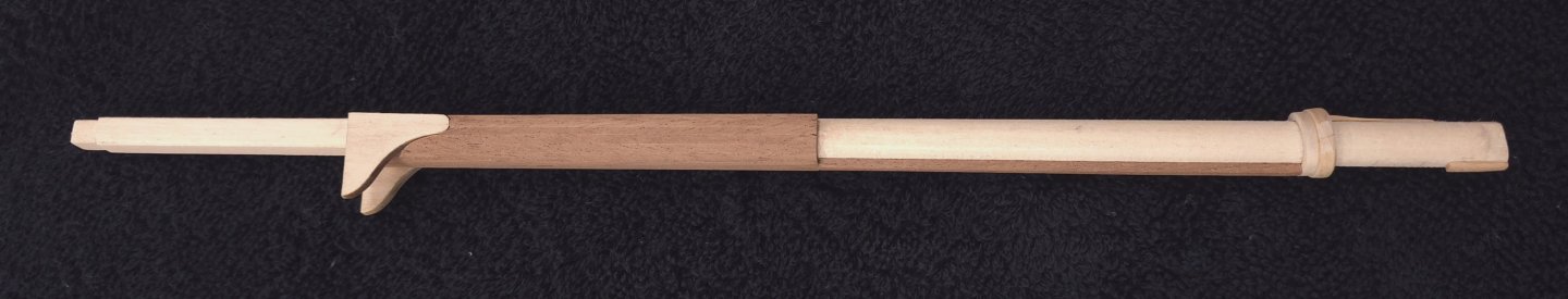
I am resuming work on the masts by adding the chafing fish. It took me awhile to figure out how I would go about beveling the strips used for these, but I think I've settled on something effective. I was fortunate that the Constructo kit came with some sapele stock in 2 mm square. Just enough, I hope, to be able to do all three of my masts. The color on this matches perfectly with the stain I've used elsewhere on the model, so I'm making use of the materials I have on hand. Some math was required to be able to determine the angle of the chamfers on the strips, I'll spare you the details on that. For the fore mast, the angle was 9° on each side of the strip. I constructed a jig to hold the 2 mm Square stock firmly while I planed away the 9° chamfer. I set the angle on the table of my bandsaw to match the bevel angle on my fixture. Note: these photos were from my first pass of making the jig, where I forgot the bevel on each side of the strip needed to be half the total angle. Below is pictured an 18° slice. On the second pass I used the correct angle of 9°. Oh, to create a shelf for the strip to rest on, I used some material slightly thinner than 2 mm and glued it the length of the short part of the jig. Positioning was easy, I just followed the line at the first laminate. And the second strip is there so that I can apply even pressure with a clamp later At this point, I have the angle set for 9° per side. The screws on the larger part of the jig hold the piece flush to the other side. The clamp on either side of the jig applies compression pressure so the strip doesn't move. I might have to make two more fixtures with slightly different angles to accommodate the main and mizzen masts later. I'm hoping that won't be necessary, as the differences will be modest. I'm hoping that I can use the same tool for all three masts.


-
USS Constitution by mtbediz - 1:76
Der Alte Rentner replied to mtbediz's topic in - Build logs for subjects built 1751 - 1800
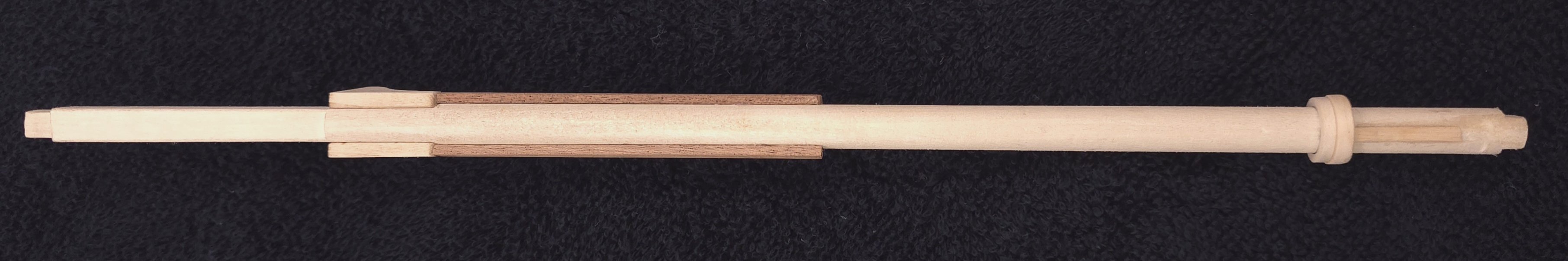
I made a jig that actually works well to taper these strips. Rather than clutter your build log with my photos and ramblings, feel free to take a look at mine in a little while. No clips or sander involved, and I was able to dial in the exact angles.. I will post one photo here showing the result, however. 😁
-
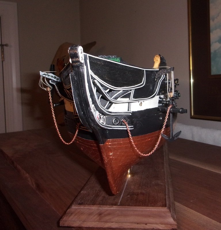
I’ll am curious to see where the anchor rope is finally lashed off topsides. to a cleat on a bulwark? or elsewhere? I also like the touch with the “ puddings” on the rings. I may yet add these to my Connie’s anchor rings. Lastly, I’m just noticing the beagle figurehead. Woof! Love it! 🐶
-
USS Constitution by mtbediz - 1:76
Der Alte Rentner replied to mtbediz's topic in - Build logs for subjects built 1751 - 1800
oof! That’s exactly how I pictured you doing this. I keep hoping to find a better way to chamfer to these with some degree of precision, but given that I’m trying to make use of either the 1mm x 2mm or the 2 mm square Sapelly that came with the Constructo kit, for this (so I don’t have to stain anything - the color is almost an exact match, I’m trying to find a way to hold these strips fast onto a board and use my dimensioning drum sander to achieve the chamfer. I have a feeling, I’ll be following in your footsteps before long. Thanks again for your assistance. -
USS Constitution by mtbediz - 1:76
Der Alte Rentner replied to mtbediz's topic in - Build logs for subjects built 1751 - 1800
Hi Mustafa, I’m sorry I waited so long to ask this followup question, but when you made the chaffing fish, how exactly did you use metal clamps and a sander to do the chamfering? I vaguely remember hand sanding a bit of a chamfer on the hull planking and could probably reprise that process, but if I could automate this instead, I’d prefer the consistency. thanks in advance. Peter -
Looking around finished builds, I found this by tidbinbilla... I don't like the starboard side arrangement. Portside looks very much like what I've settled on. I may yet add that chain going to the Hawser, but to Jon's point, nearer the end of the project.
-
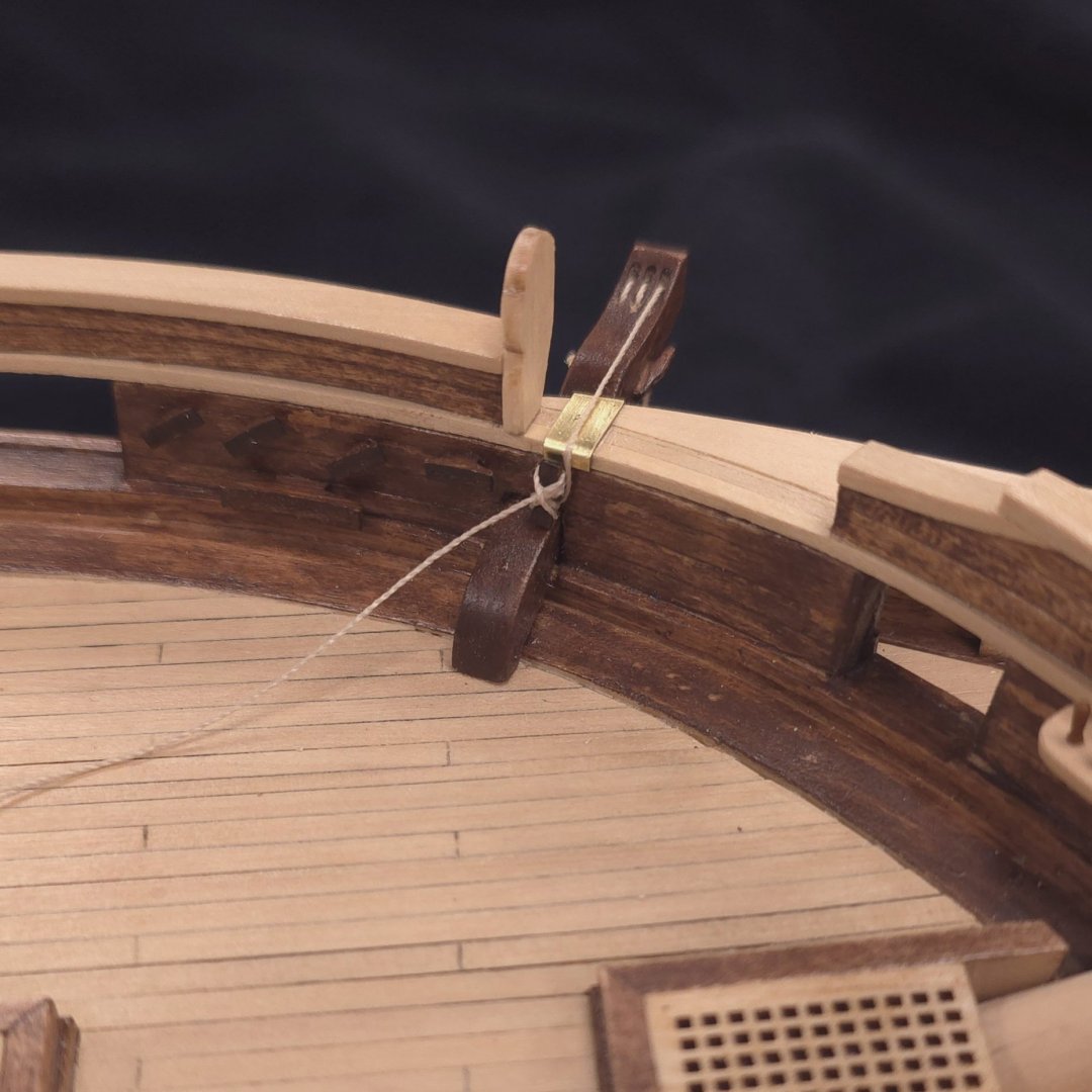
Ha! It's a little late to put them aside, given that they're glued in now. However I am thinking about clamping a reinforcing block onto the main rail to make bumping it off a lot harder. And thanks for keeping my secret..😁
-
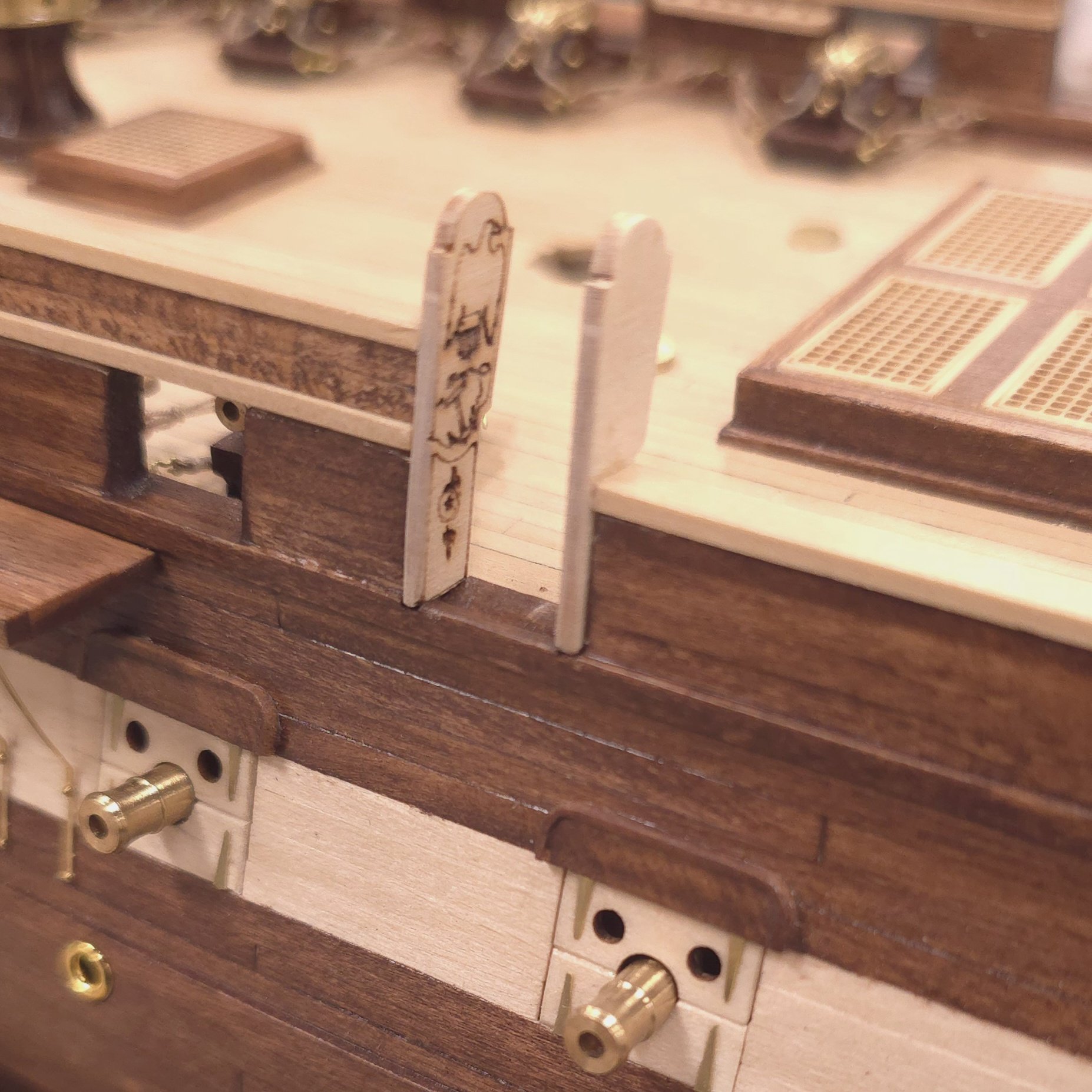
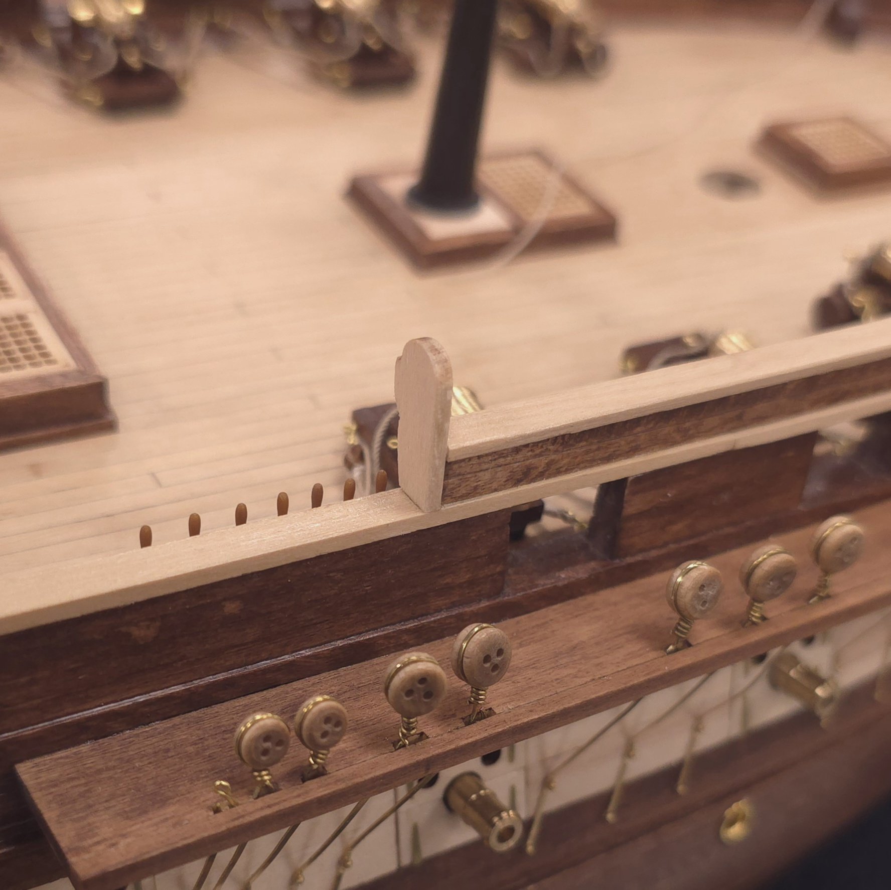
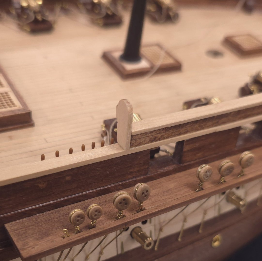
Thank you gentlemen. Unfortunately, I don't think the video explains why Bob Hunt rigged the anchor in his practicum the way he did, or why the anchor rope in the photo of Connie today is tied off on the cleat above the cathead. Perhaps this is just meant to show the anchor in an intermediate state after pulling but before stowing. Pull the anchor chain in until it's along side and ready to "fish". Then use the rope to temporarily hold the anchor in position until it can be secured in the anchor port on the spar deck. I'm not that much of a stickler for authenticity, and I do like the way the anchor looks with the cathead and triple block arrangement, so I may just keep it and hope noone asks. Moving on to today's activity.. I started installing the gangway boards. But I am concerned about the forward one at the waist. I have a feeling it's not going to last terribly long. So much of it extends above the main rail, that it's just a matter of time before it gets nudged and snaps in two. And yes, I did use the decorated ones at the waist. I've been holding off gluing in the fife rails. That may be next on the to do list.

-
Does anyone want to venture a guess as to how much anchor rope the Constitution carries per anchor? Where is this rope stowed? And how is this anchor deployed? Looking at the picture that Mustafa provided, I don't see how this anchor could possibly be used effectively given the scant amount of rope evidenced in the photo.