
Der Alte Rentner
-
Posts
259 -
Joined
-
Last visited
Content Type
Profiles
Forums
Gallery
Events
Everything posted by Der Alte Rentner
-
I have the same issue with the material that came with the kit. I tried three approaches to deal with the problem. 1. I asked Model Shipways to provide replacement strips. (No response since their acknowledgement email on December 1, 2023.) 2. I ordered replacement strips from Modeler's Sawmill. Unfortunately the strips were significantly darker than the basswood that came with the kit. Because I was/am still hoping to keep a natural finish, these were not usable. (They were also significantly shorter - I'd say 2/3 the length of the stock in the kit, so ask about that when you order). 3. I went to Ace Hardware and purchased material that was a tad thicker than the kit's stock, and used my thickness drum sander to get make my own replacement strips. The color was an exact match, and the strips were spot on in their dimensions.
-
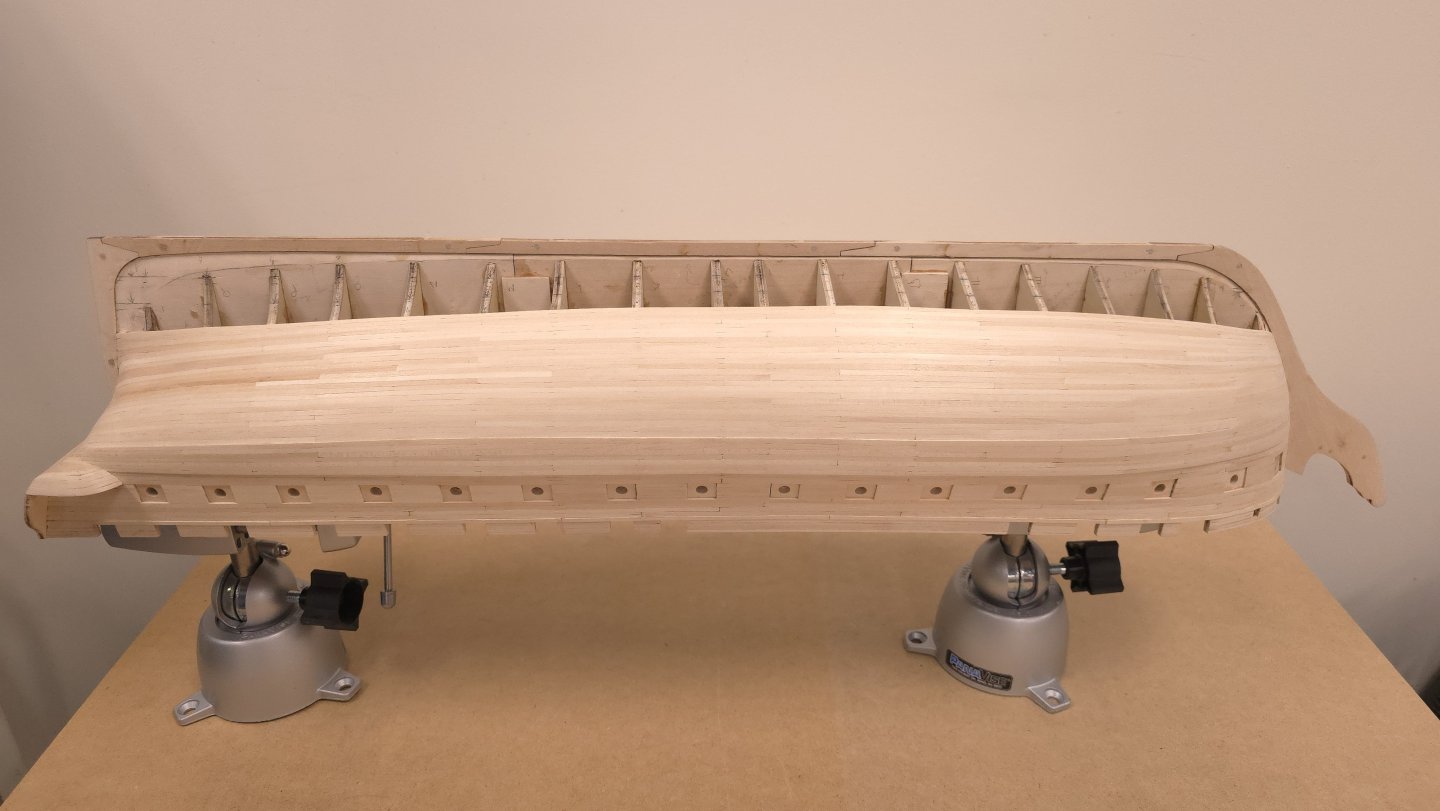
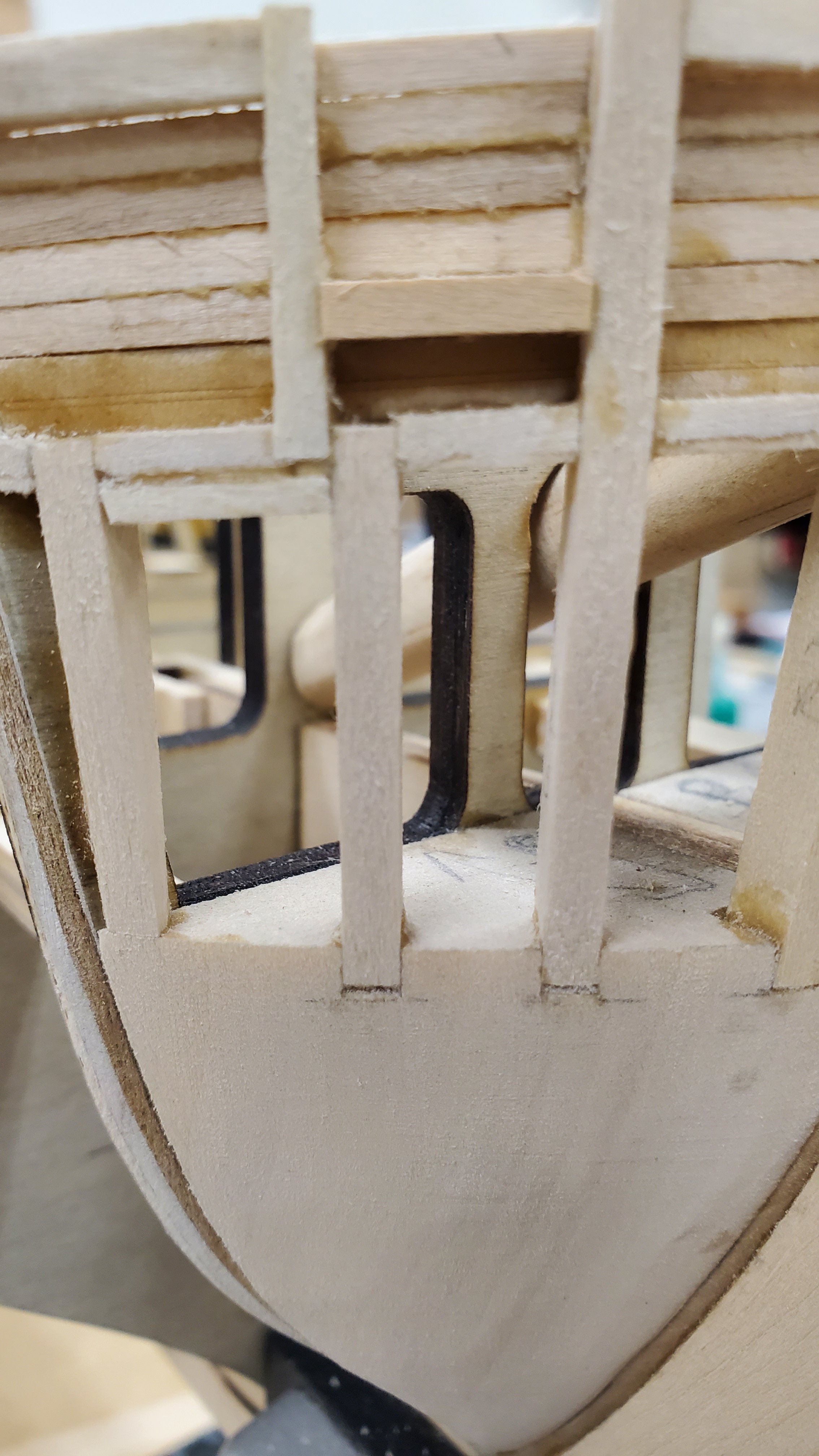
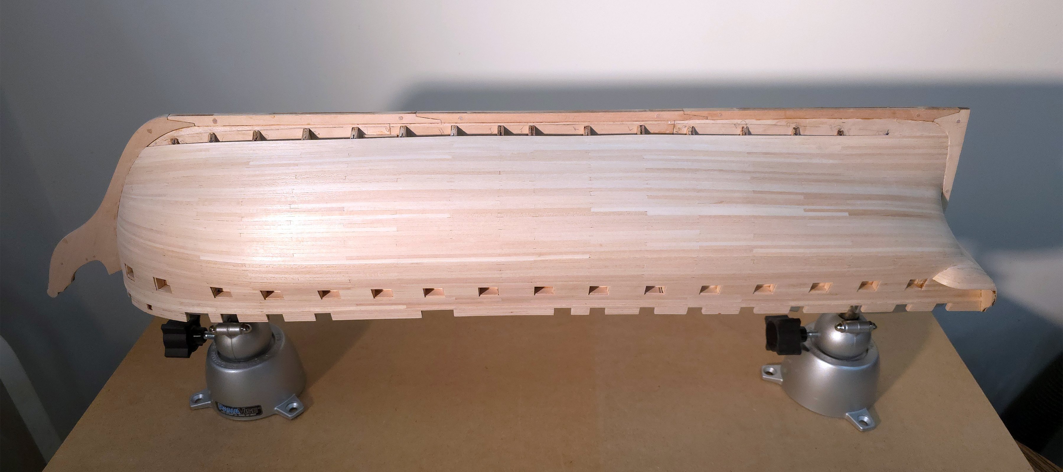
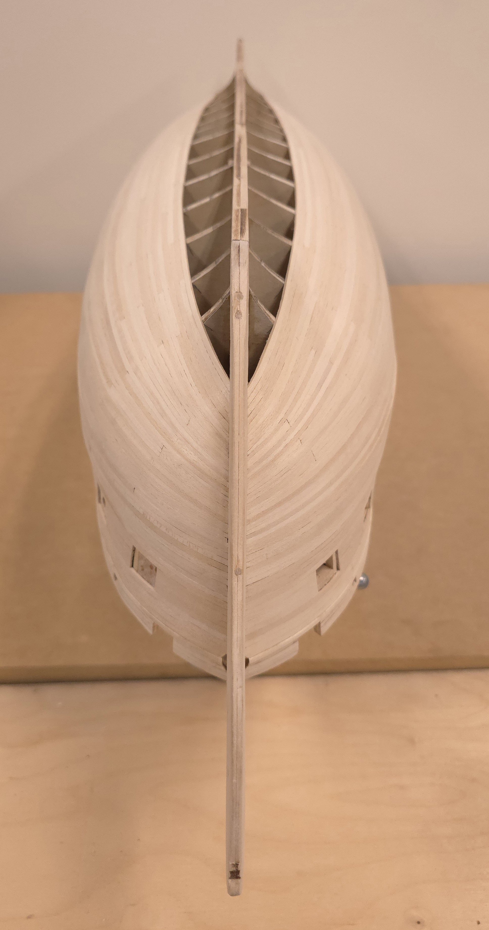
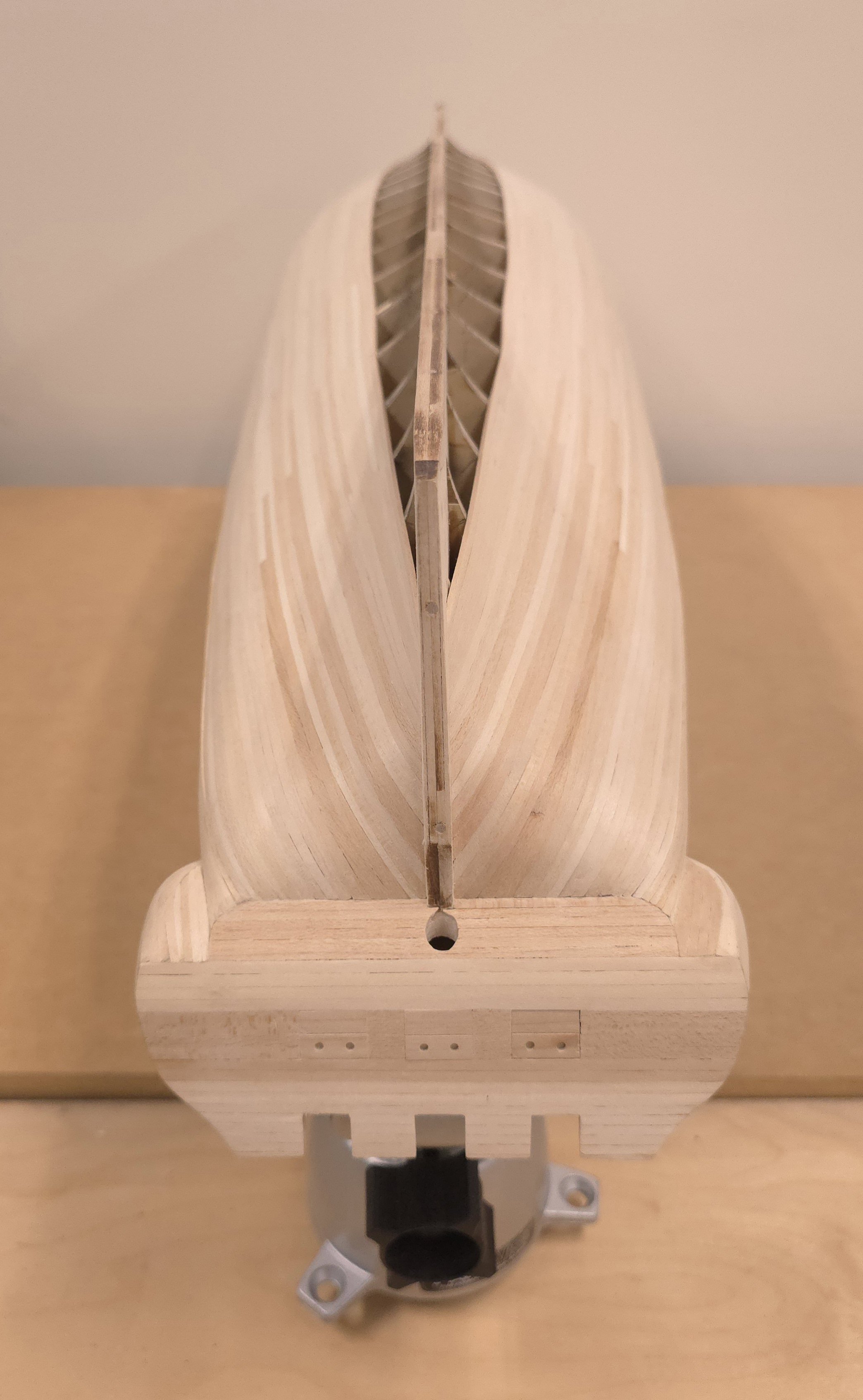
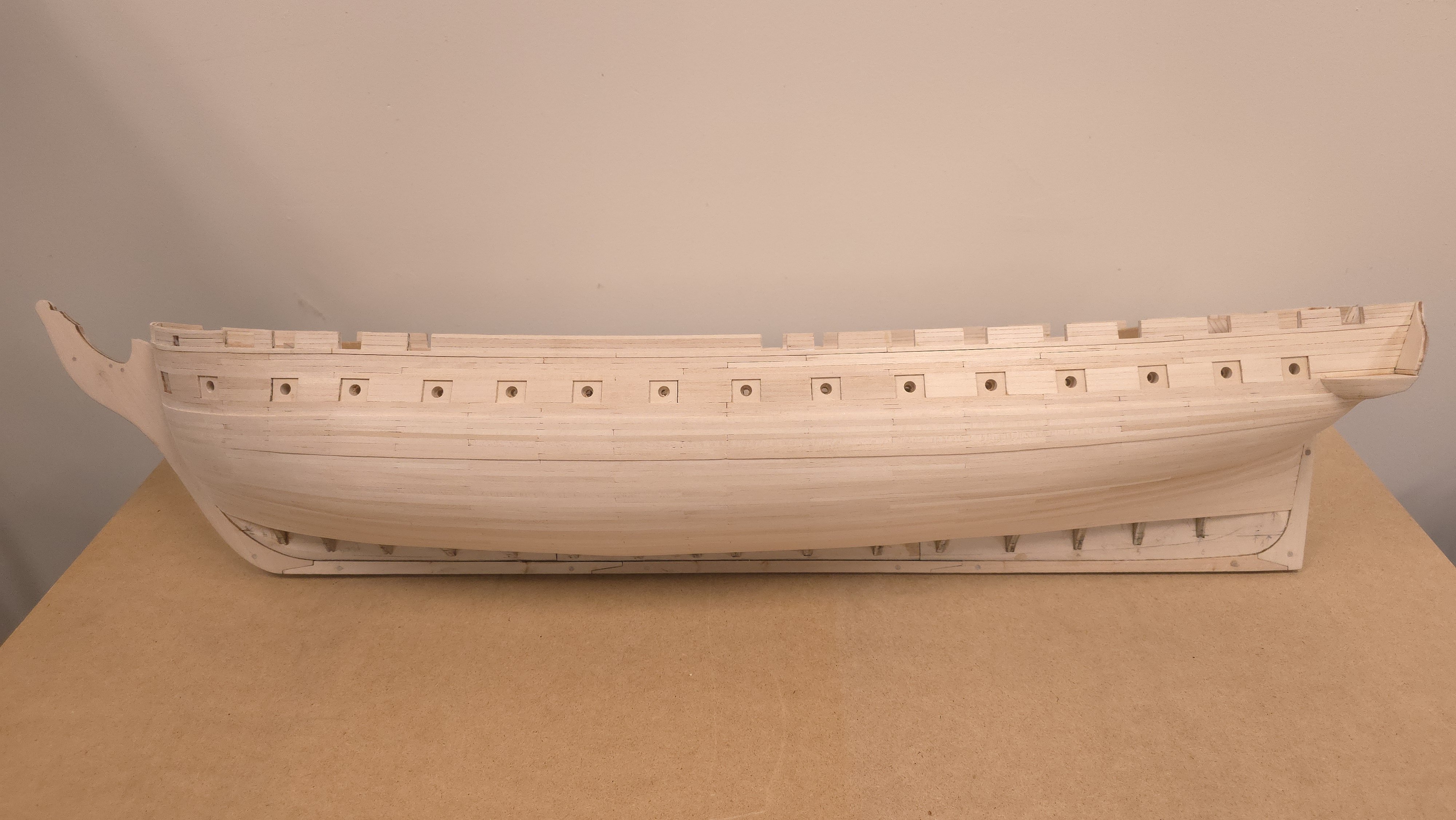
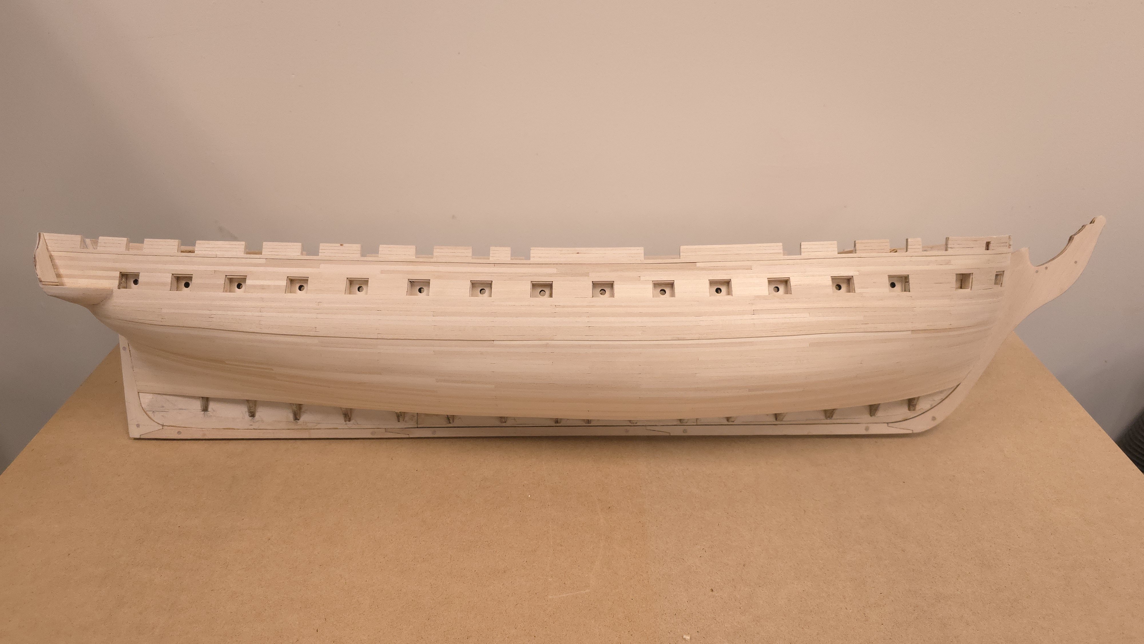
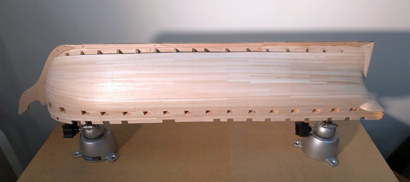
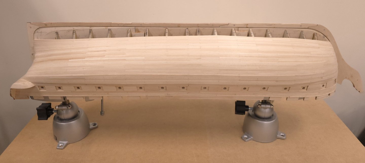
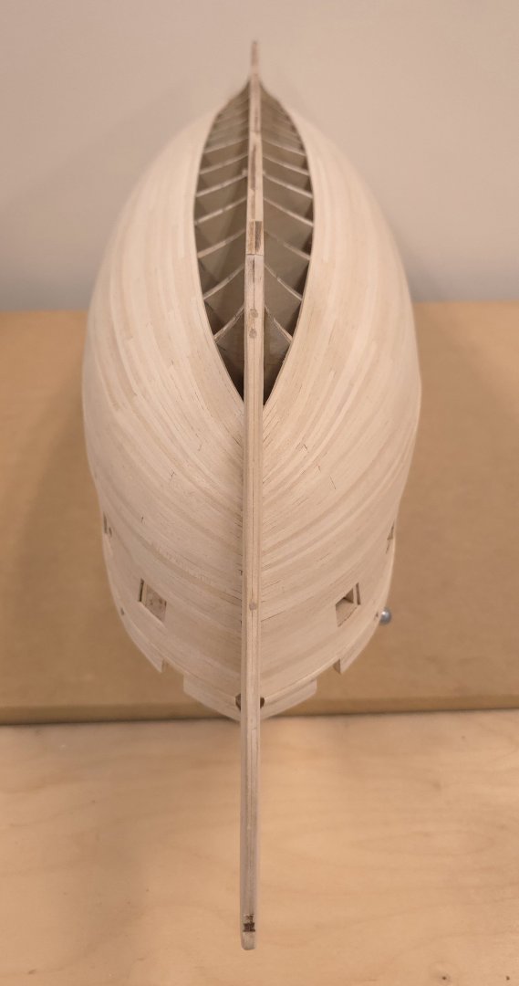
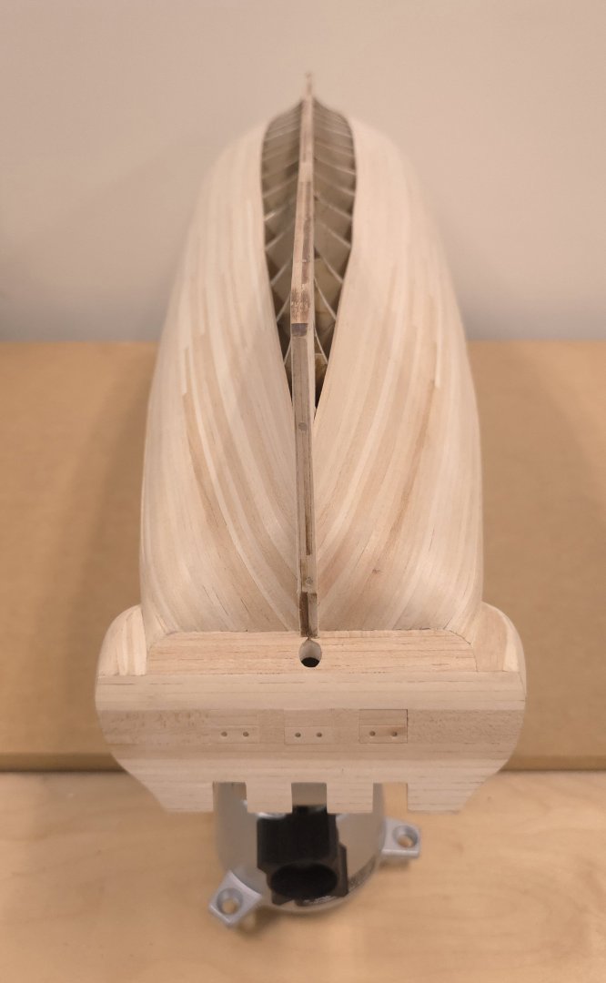
I couldn't resist posting this pic. Five more strakes on the port side and the hull will be fully planked. (I did fit the garboard strake there yesterday, so I'm close to being done.) One lesson I learned was that the fairing process at the onset - as well as that of carving of the rabbets at the bearding line, needed more attention to detail. I'm paying the price now. It took two days to lay in the garboard and remaining 4 strakes in zone 8, mostly because I had to fiddle with the rabbets and bulkheads at the bearding line. Really sharp gouges of varying sizes made this doable. And had I waited to do the garboard strake last, I would have been in deep doodoo💩! The good news was that I could use just one plank there. For all the attention to planking in the "guide" (Andre's term) there's no mention of handling the garboard strake. Several resources I've consulted handle that particular strake differently than the rest and install it earlier in the process.
-
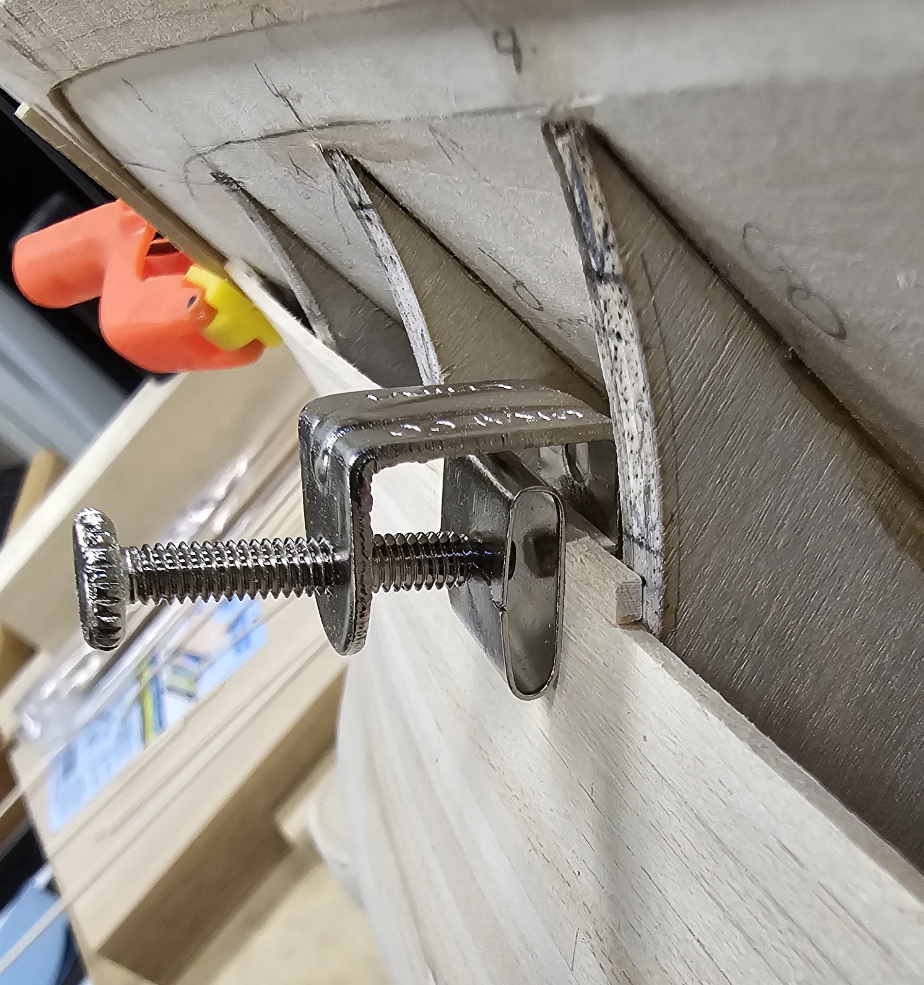
don't forget, you'll need to grind off that lip to use these as I did. (I wish I'd found these sooner in the planking process, but better late than never)
-
To all, Any advice on whether to add the garboard strake first - before I add the other 4 remaining strakes?
-
Likewise here.
-
Very Interesting. When I googled the name, I got a hit for someone associated with Anxiety Canada - a much younger fellow than this Mark who would be in his mid 70s today. Thank you for providing the link Gregg. The blurb on Mark there did say he built a 1/4" (1:48) scale version of the Constitution in 1990. The piece goes on to say where it was displayed for a time in its history, ending with - it "was subsequently put on loan to the Maine Maritime Academy in Castine, Maine where it was displayed for a several years." I will pursue that lead to see if I can find where it is today. I would love to see it up close. Thanks again. best Peter
-
Simply stunning Jon, I don't suppose you know the scale? I'm guessing this is a fairly large model, judging by the details I'm seeing. Thank you kindly good sir.
-
Aha! That is the just nugget I was prospecting for. I'm fairly technologically apt, using photoshop and word to produce my own pdf version of the build log. You'll see what that looked like in my earliest posts. Because I wasn't seeing the resolution I desired posting pdf log pages, I switched to using the site's photo upload features. I generally prefer high resolution photographs - so I can zoom in for more detail. Hence I haven't really needed to post pairs of photos side by side, but thought about doing so today. Thanks for sharing Gregg! and, the Blue Nose may be my next build, if I ever finish Conny! 😉
-
USS Constitution by mtbediz - 1:76
Der Alte Rentner replied to mtbediz's topic in - Build logs for subjects built 1751 - 1800
It is indeed! Thank you. And keep up the impressive work. -
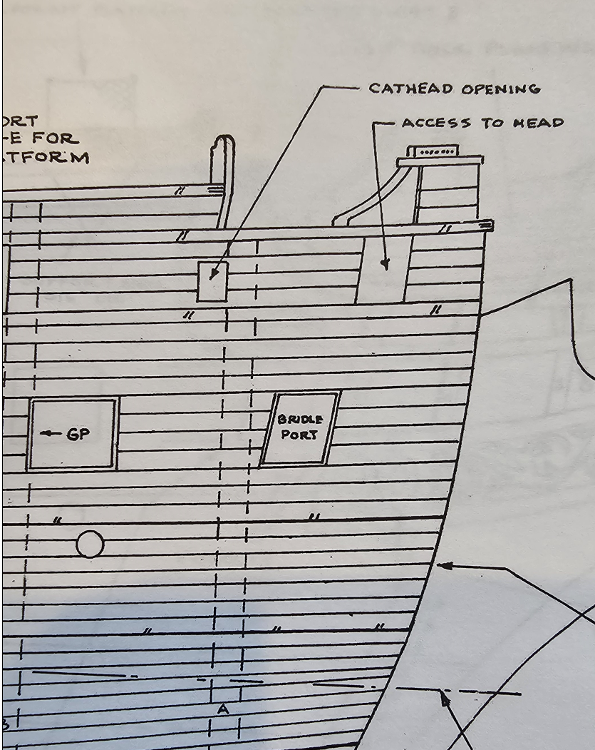
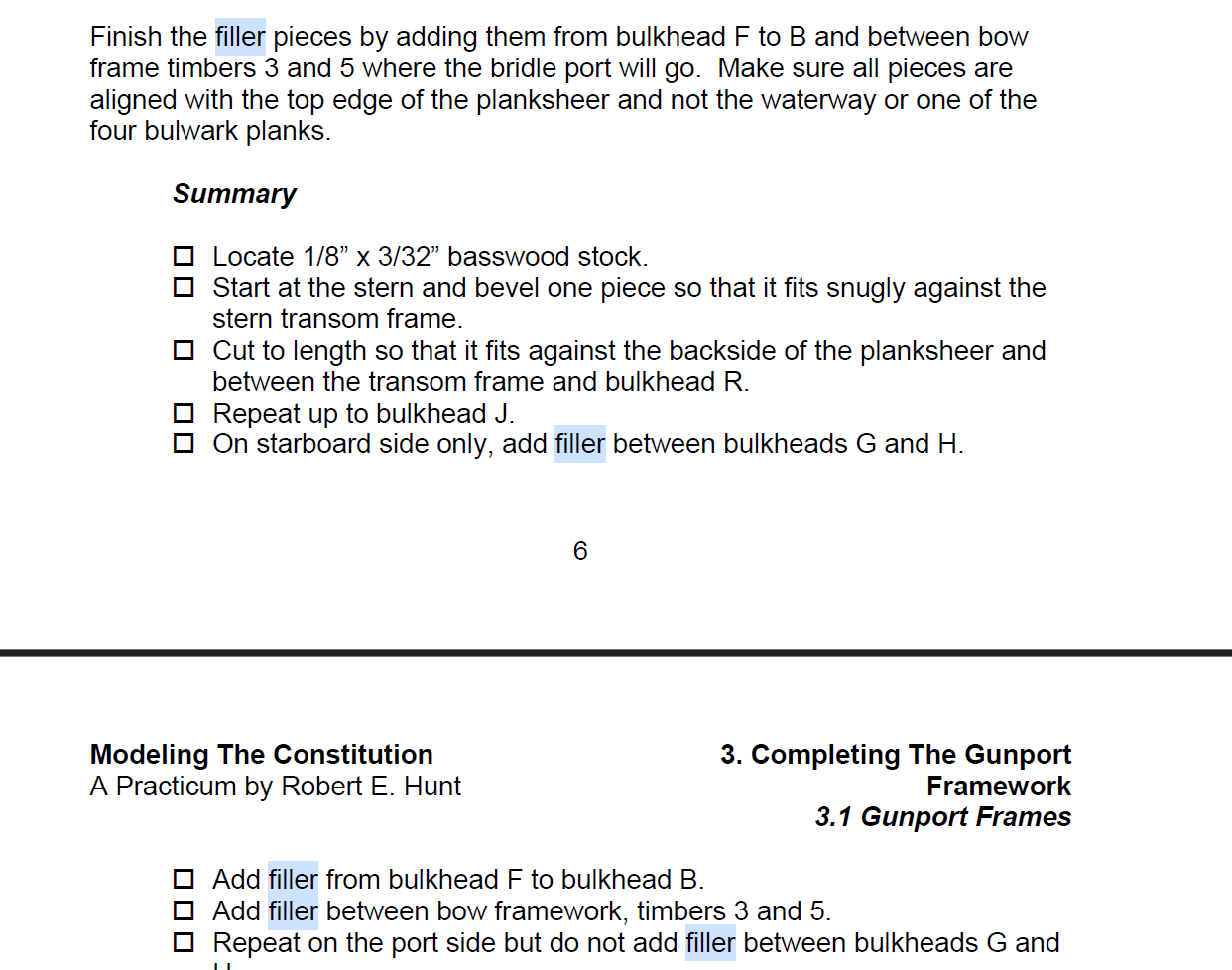
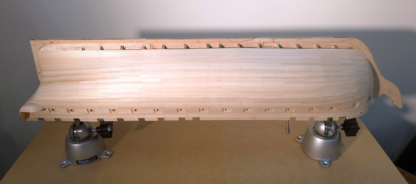
Okay, I just took a snapshot of the plans. The access to the head seems is between timbers 2 and 3, while the bridle port resided between timbers 3 and 5, which is where the "guide" says to put the filler. However, it's now obvious to me that the planksheer is well above the bridle port. Therefore, I too have no idea what Hunt was talking about in this case. In general, I've learned that wherever you have planking (or in this case, planksheer) going over a curved span, it's not a bad idea to have filler material underneath to aid in maintaining the curve. Is it necessary here? Not sure, but as you can see, I did the exact same thing that you did. Also, you too got to my first response before I changed my original reply to your question.

-
USS Constitution by mtbediz - 1:76
Der Alte Rentner replied to mtbediz's topic in - Build logs for subjects built 1751 - 1800
Jon, Where did you get the photo with the 1797 version below? I'd love to see more photos of the hull. I like the contrast between the painted uppers, and the natural finish on the bottom. Thanks Peter I apologize in advance to Mustafa for bogarting in on his build log. These photos came from an earlier post in his build. Feel free to delete. -
USS Constitution by mtbediz - 1:76
Der Alte Rentner replied to mtbediz's topic in - Build logs for subjects built 1751 - 1800
Hey Mustafa, What are you using to take those closeups - especially the likes of the mast bitts? A camera with a macro lens? or your phone's camera? Thanks Peter -
(P.S. to Scottish Guy, I just edited my reply because, in the first go-aroung, I answered the wrong question. I though Andre was asking about the support for timber 4).. No, Bob's right. The bridle port is between timbers 3 and 5, if I read the plans correctly just now.
-
Greg, How are you formatting your photos in these posts? Or asked another way, how are you getting photos to appear side by side? Thanks Peter
-
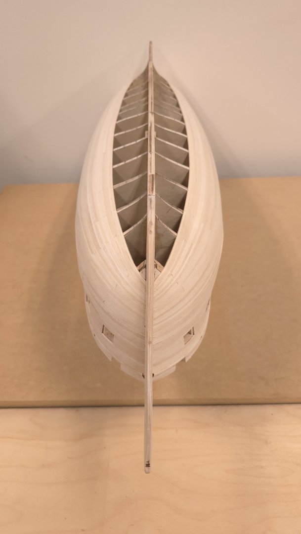
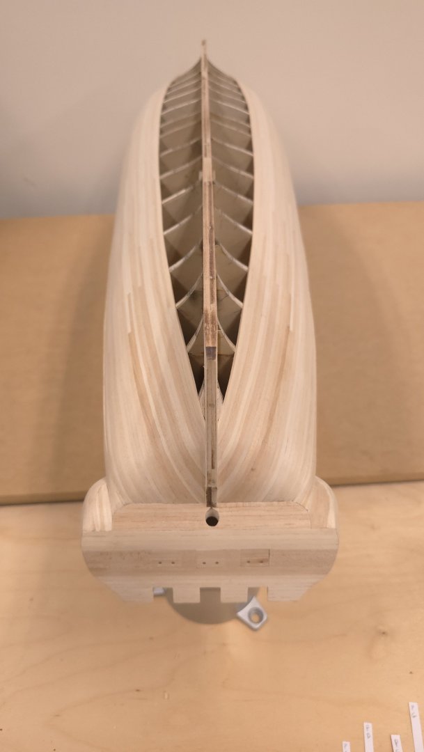
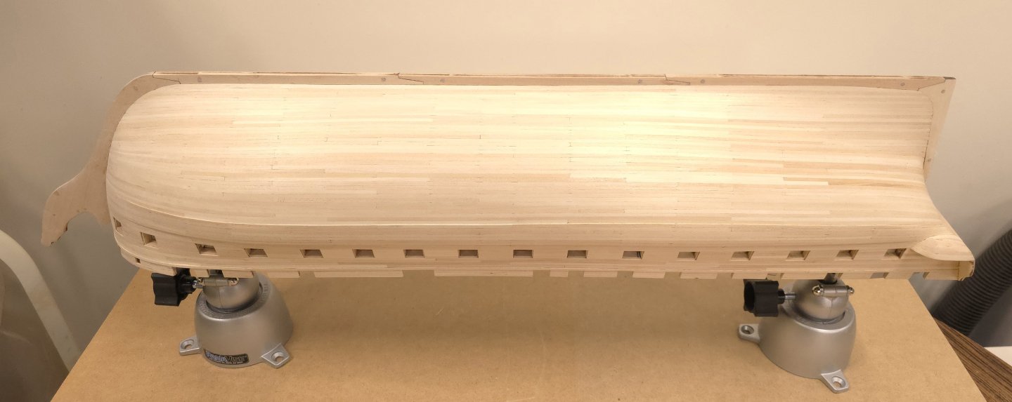
7 down, 1 zone to go. I am sooooo ready for this to be done. Barring the unforeseeable, one more week should do it. (P.S. to Rita and Clement. Touch base if you're following along, thanks)
-
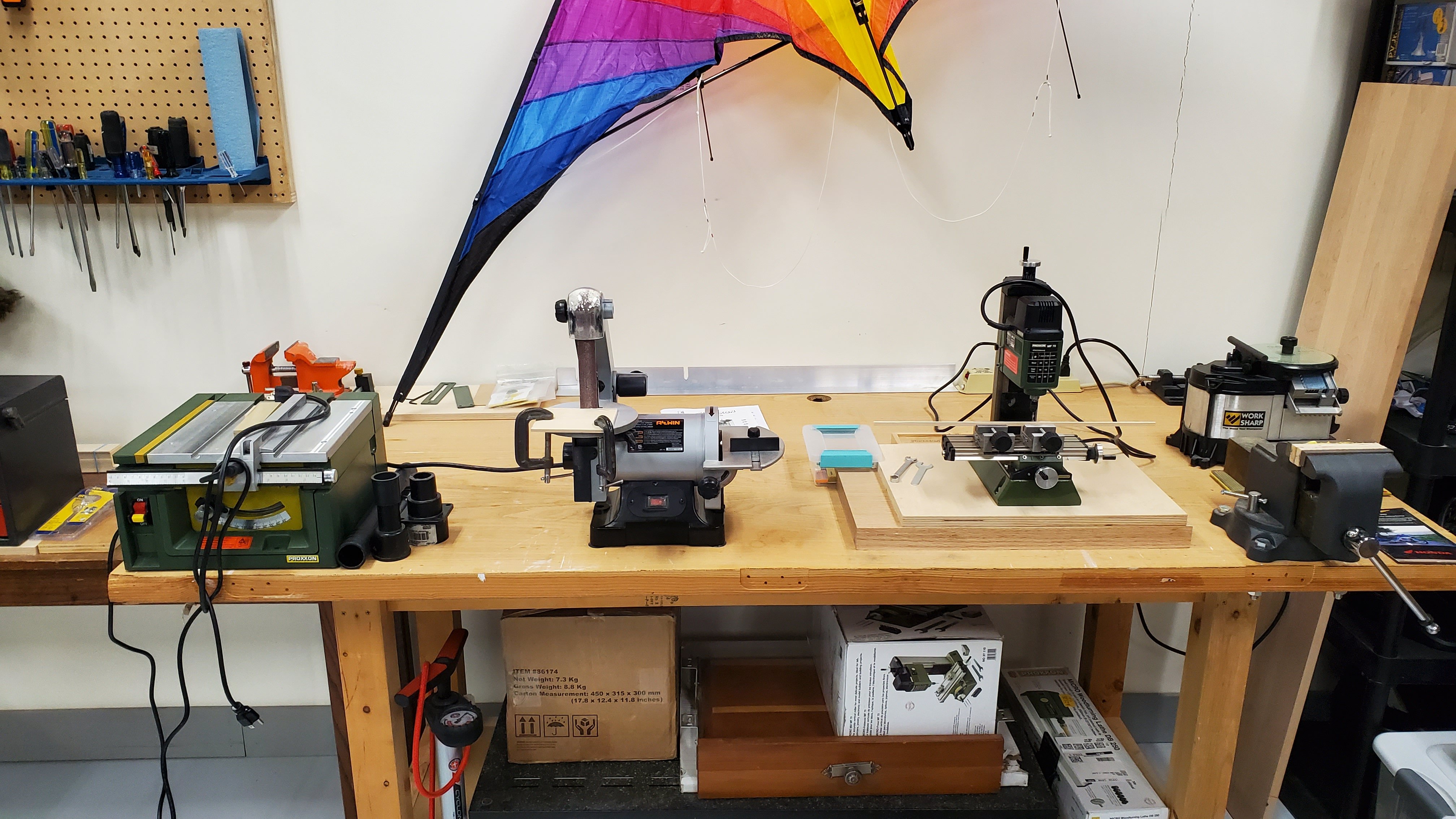
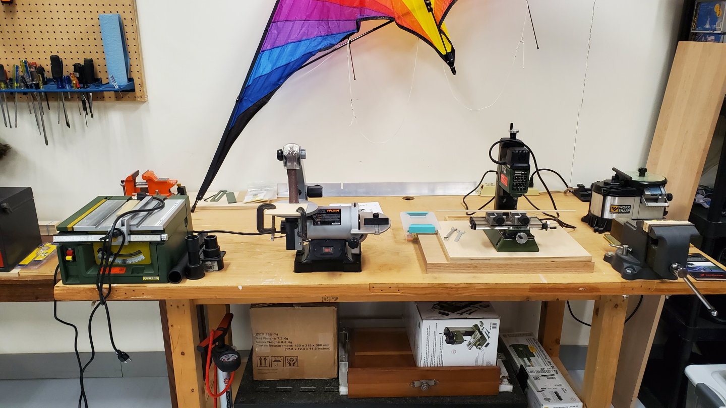
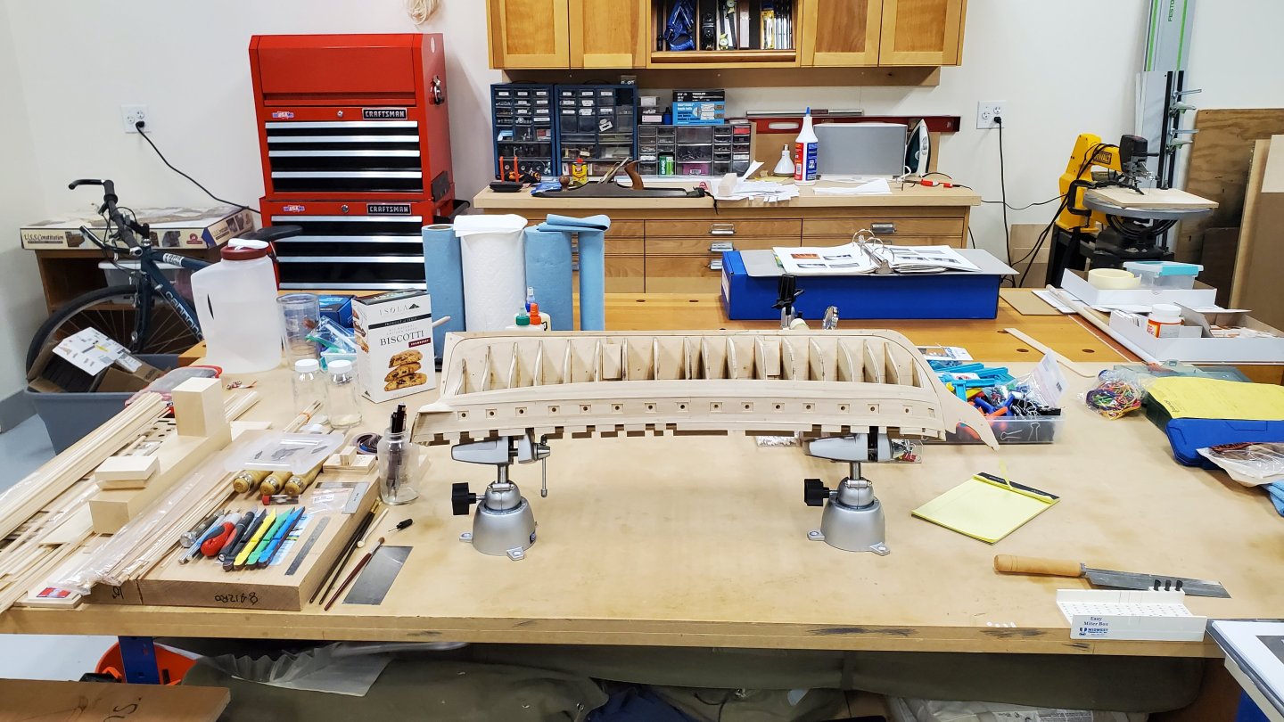
I actually have my own shop in a light industrial mall that is my home away from home. This is the work area in the back where I've been doing my woodworking projects these last 14 years. Before I had the shop, my gear was in the basement of our home. When we moved, and I saw the dust everywhere in the house, I decided to move the shop to another building. While I have no views, I can open the man door in the front and the garage door in the back and enjoy the weather inside when it's pleasant. Not visible in these views are bulk of my power tools. Table saw, band saw, sliding miter saw, router table, spindle drum sander, belt drum sander, drill press and two dust collectors - one on each side of the shop. I will be getting rid of most of that stuff as I transform the shop into a garage-o-minium in the next couple of years.
-
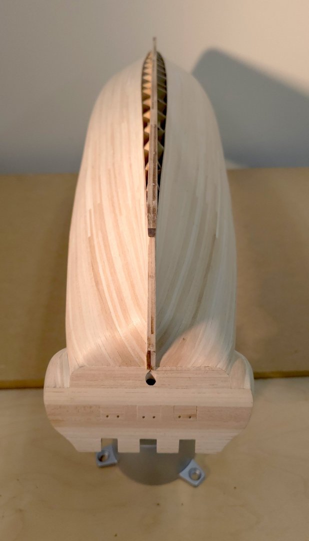
It's hard to put into words, but those gaps are hard to get planks to lay right. Material hardly matters. Use balsa or basswood - something easy to shape. You only need enough to span the space between the bulkheads where ever the planks would lay. Funny, I could not find this build at Model Ship World, neither did a search of Niagara or filler blocks. The idea is simply to have something to hold the shape of the planks at the bow and stern. Extra surface area is a plus for gluing too! It doesn't need to be pretty, just to be flush at the bulkheads. If you use really soft wood, balsa e.g. shaping with hand tools and coarse sandpaper should not be much of a chore. Because balsa is even softer than the basswood that came with the kit, this should be easier to do than the filler blocks you already installed at the bow.
-
USS Constitution by mtbediz - 1:76
Der Alte Rentner replied to mtbediz's topic in - Build logs for subjects built 1751 - 1800
Everything looks great! You're setting an incredibly high standard for those of us following along behind you. Keep up the fabulous work. -
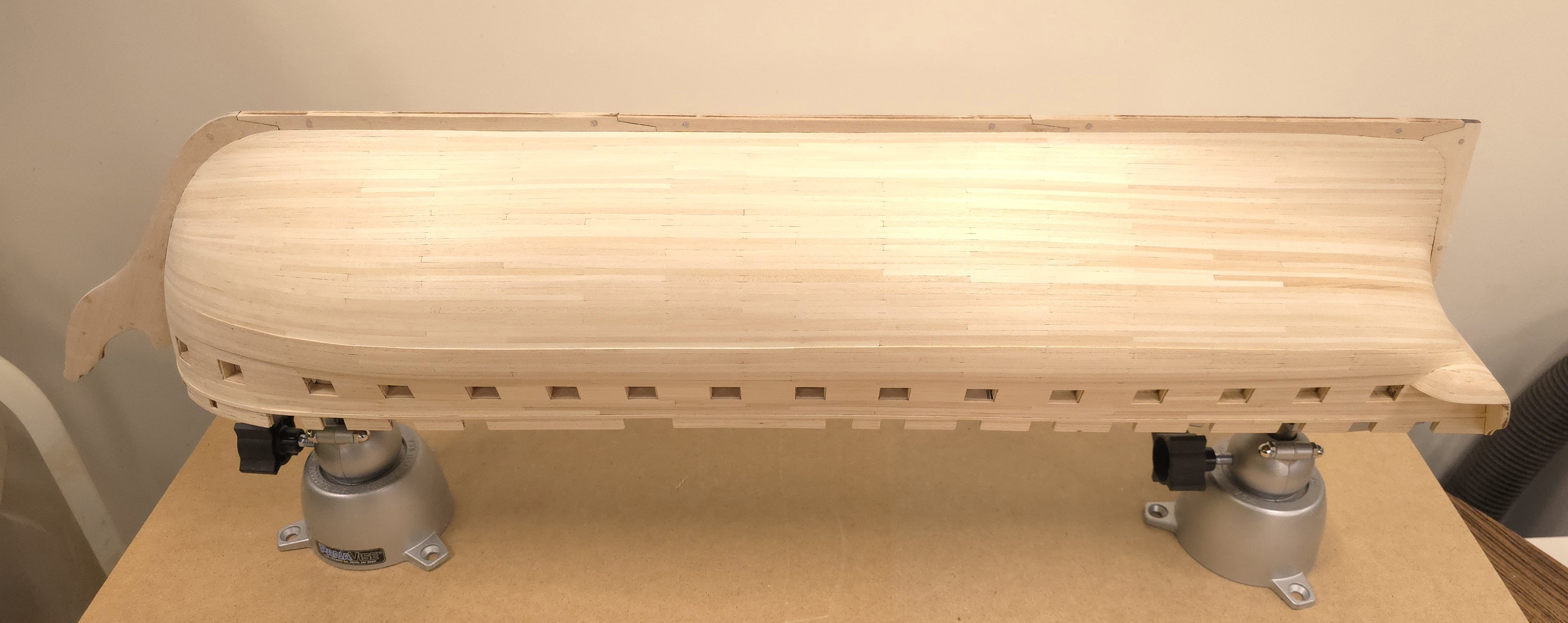
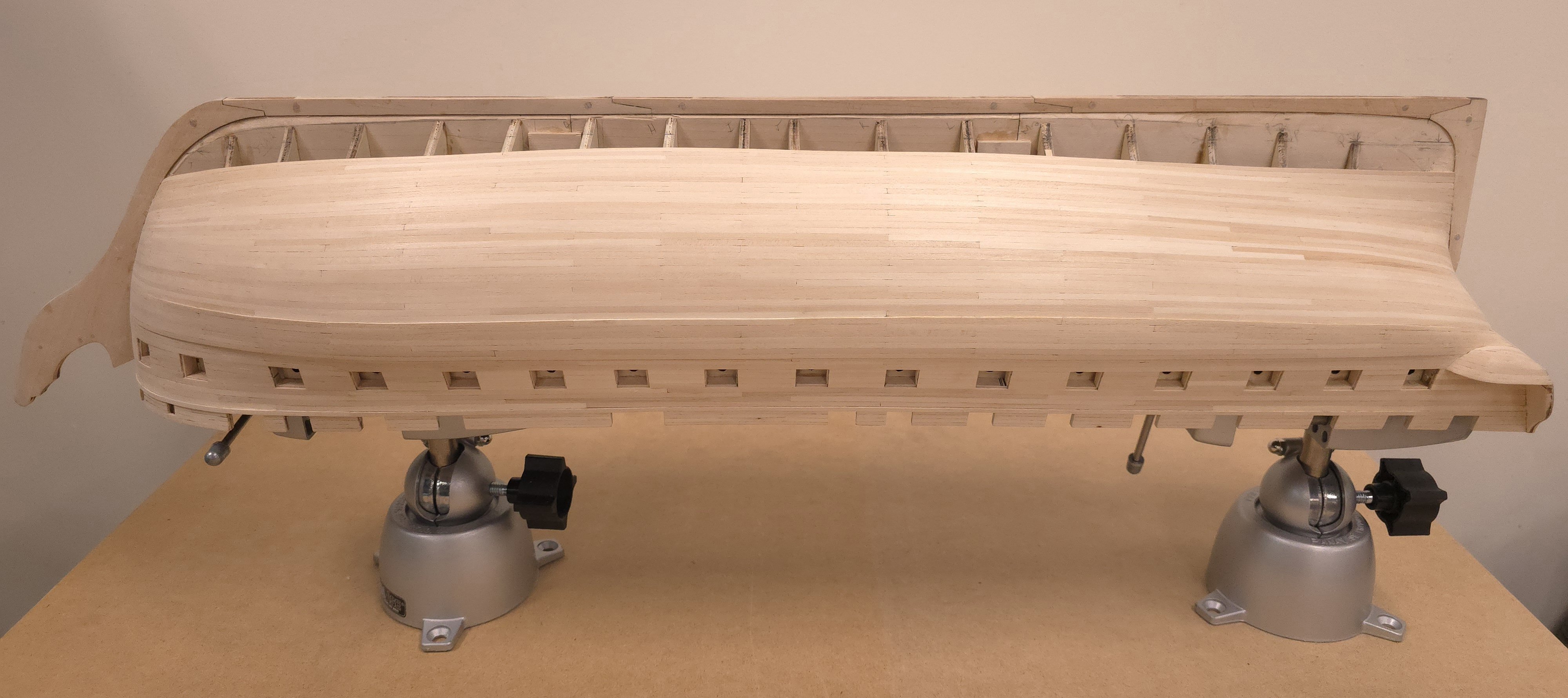
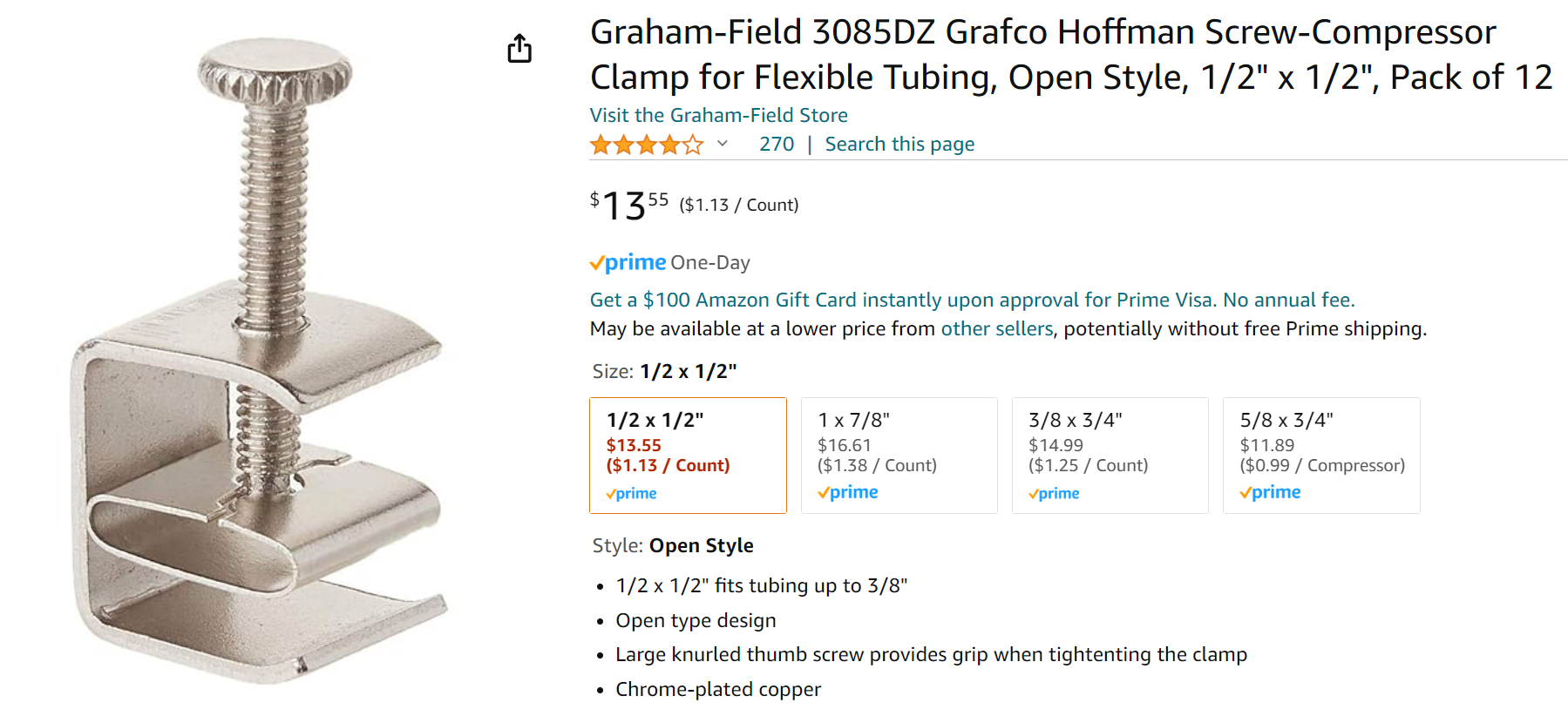
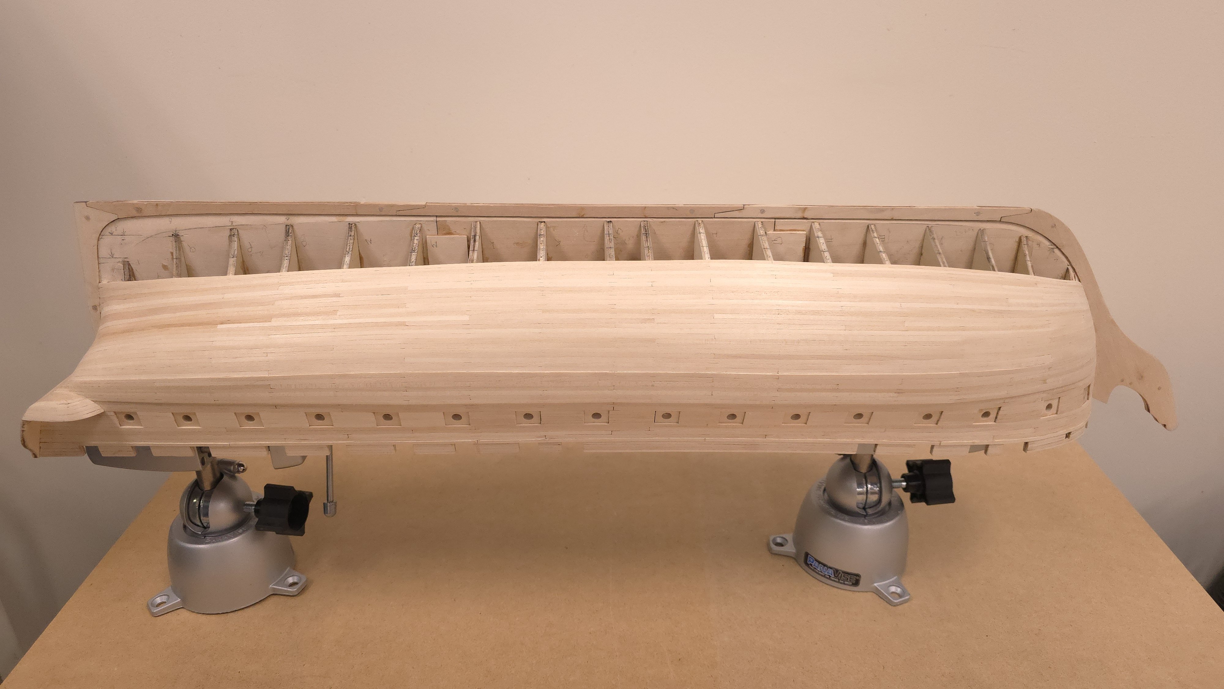
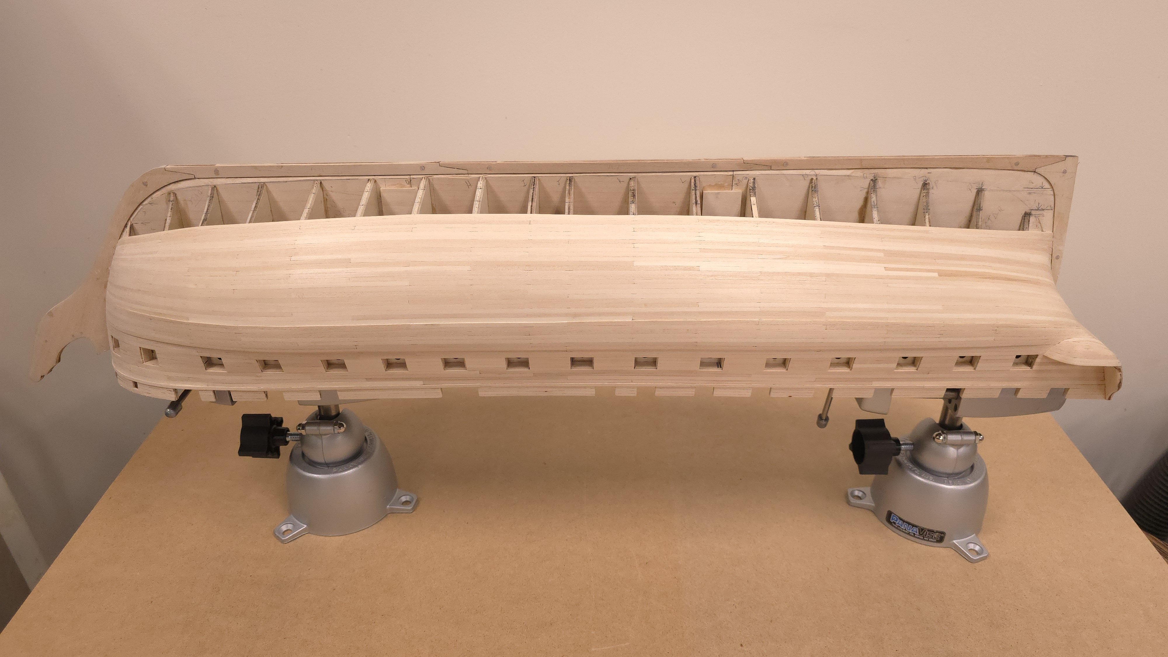
Six down, three zones (or 10 strakes) to go. Man-oh-man, am I ever ready for this stage of the build to be over! I found some clamps at Amazon that, with a small modification (grinding flat the curved portion that is not visible in the photograph below), works well in the tight spaces I have left. (See last photo in today's batch) 1. That clamp in action: On to the build. First, work-side up: Then for a change of pace, right side up. The clamp ad at Amazon: Note, I tried gluing a wooden shim on the inside face at the bottom of the clamp as pictured below, but it didn't stick very well. In the end I simply ground off that lip using my belt sander, which made short work of it.


-
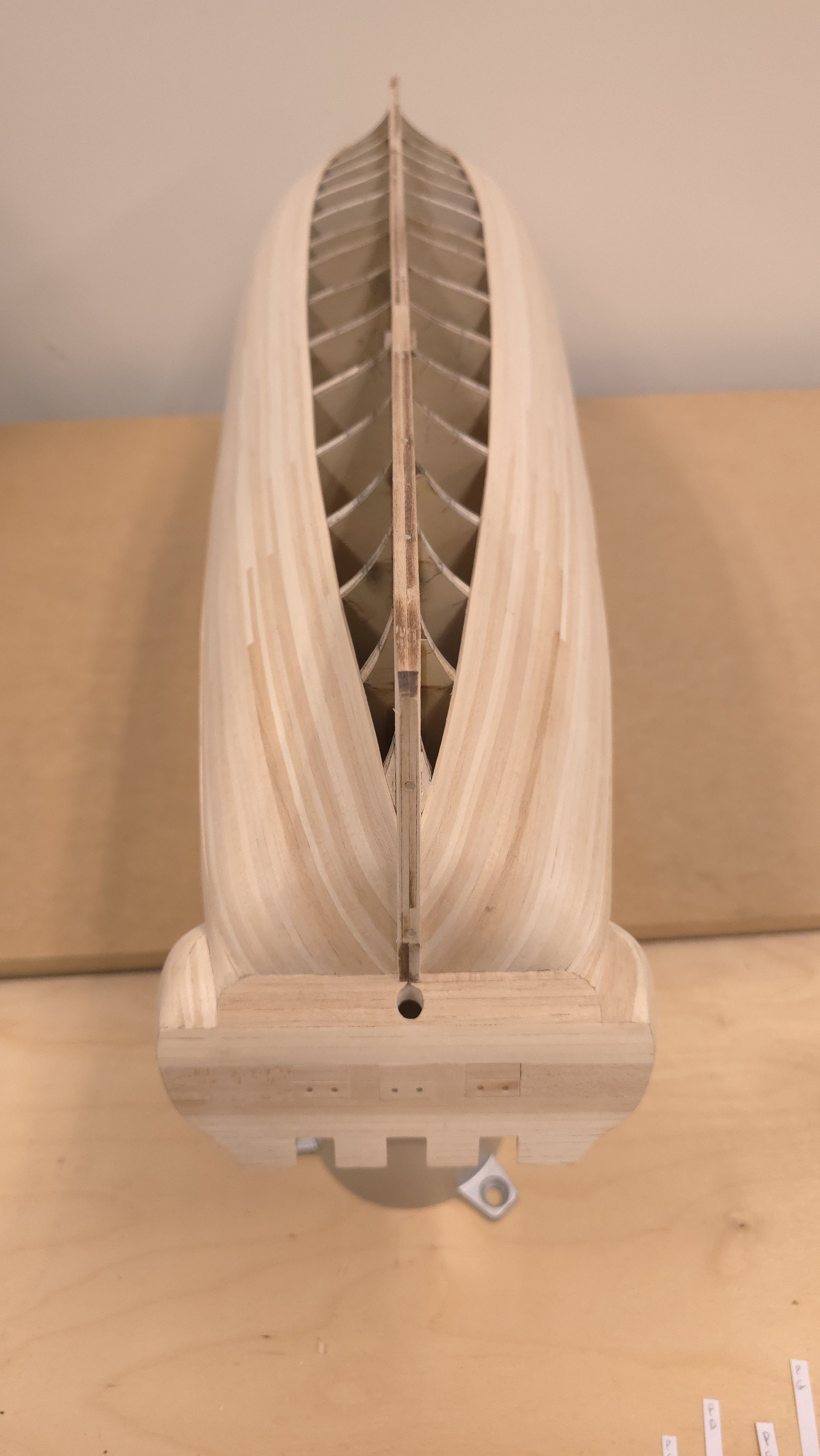
whatever floats your boat.. Great fit! by the way, I noticed you only have the one pair of filler blocks at the bow. You may want to consider add at least one more pair between bulkhead A and B. As I wrap up my hull planking, I really wish I'd done this - as well as putting blocks between B and C, and R and Q. In perfect 20/20 hindsight, I believe doing so would have greatly simplified hull fairing and planking.
-
Egad! As I struggle to finish the last 11 strakes of hull planking and wishing it were OVER, I am glad I opted out of the gundeck kit bash. Love your attention to detail and the math. Keep up the great work!
-
Your photos (and Jon's) prompted my own stroll down memory lane. One of my celestial navigation practicums took me from Nassau to Mystic aboard the Regina Chatarina in October of '98. Sadly, I only had a small handful of photographs and they were printed on matte paper, so digitization didn't net the best result. I really miss blue water voyaging.


-
Yes, I did cut it in the bowsprit. I don't recall this being a problem at all. Checking my notes, I saw early on that bulkhead B needed the slot for this tenon, so I cut the mortise before installing the bulkhead. I found the correct angle and fabricated a test piece to verify that then and there. Later when I whittled the tenon, I had that angle handy as a reference. I went back to those two portions of my build log but sadly neglected to note details of the 'whittling' process. My guess is I did exactly that. Thinking about your idea, I don't see the advantage to doing the plug thing. I've thought about this from time to time since them, and I'm not entirely sure the tenon is even a necessity. Seems to me, if you're careful about things, you can simply glue the end of the bowsprit to the bulkhead - when it gets to that point.
-
aha! those are indeed they. and great minds think alike. I had the same thought about the weight about a nano second after I hit "Submit Reply". I took a closer look at the clamps in the catalog and decided they are still too bulky (and perhaps heavy) for the intended use in the next two zones of planking. I may yet fabricate something small out of wood and screws. If that works, I'll post on my build log. All the best..
-
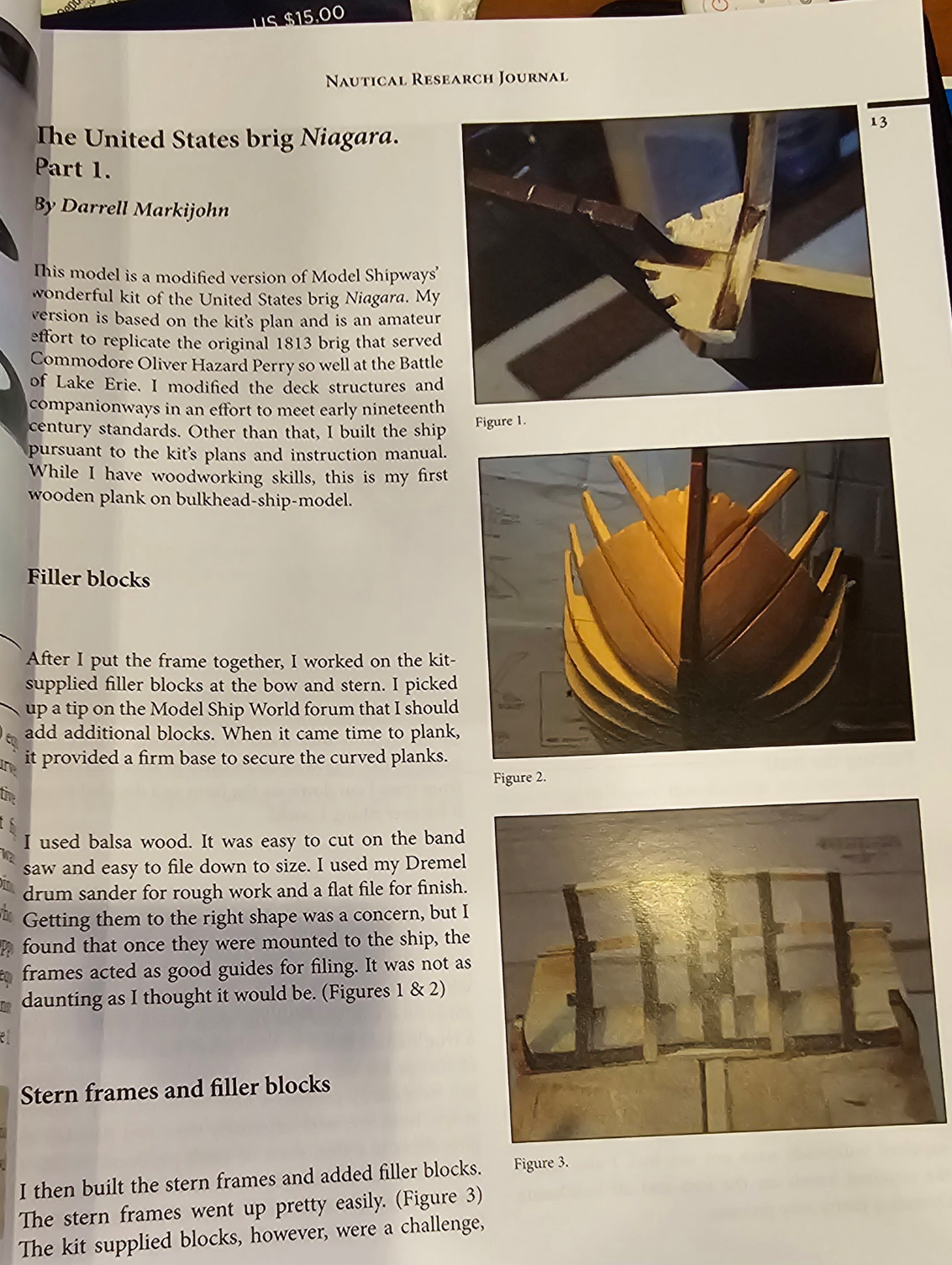
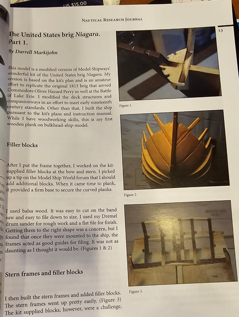
Another week, another zone. 5 down, three to go. As I was struggling with the plank work at the bow today, I really wish I'd taken the time - up front, to add some filler blocks between bulkhead A and B. Likewise between bulkhead Q and R. Getting the planks to curve properly in those areas now is problematic. Not noticeable at a distance, or right side up, but up close, where I've been spending all my time of late? Sigh.. This is not the ideal hobby for a perfectionist. April 16 Post Script - (after having read part 1 of the piece on building the Brig Niagara in the Spring 2024 Issue of the Nautical Research Journal (Vol 69, NO. 1)) : Evidently there's a forum somewhere here at Model Ship World with a tip to add additional filler blocks. The photo in the Niagara build article shows no less than three filler blocks at the bow. I amend my previous wish to include at least two additional filler blocks. Resumption of April 11 post: The good news is that the extra time getting the tick marks on the bulkheads right is paying dividends now.