Greg Davis
-
Posts
717 -
Joined
-
Last visited
Content Type
Profiles
Forums
Gallery
Events
Everything posted by Greg Davis
-
 Today I got a very good start on shaping the fillers on the starboard side of the hull. Also got a little done on the other side - if the weather is good tomorrow hopefully I will get that done as well. I like to do the bigger sanding activities outdoors if I can. While this is a big dusty project I'm glad that the fillers are going to be in place for the planking. I really don't think the bulkheads would have stayed perpendicular to the false keel otherwise. The false keel and bulkheads are made from 1/8" material.
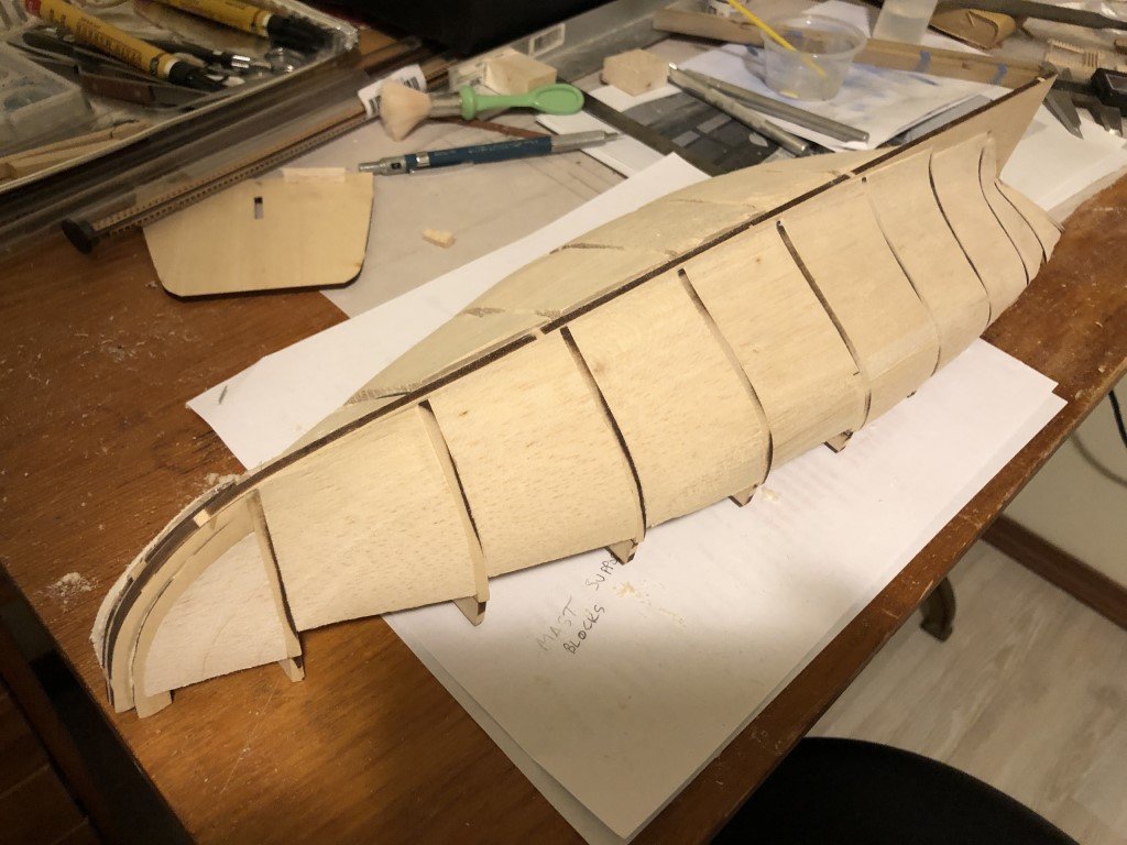
-
At one point I thought about buying the 1/96th version and building it again to see if ~20 years of model building has sharpened my skills! My stash keeps growing as well: models bought > models built and even worse rate of models bought > rate of models built!
-
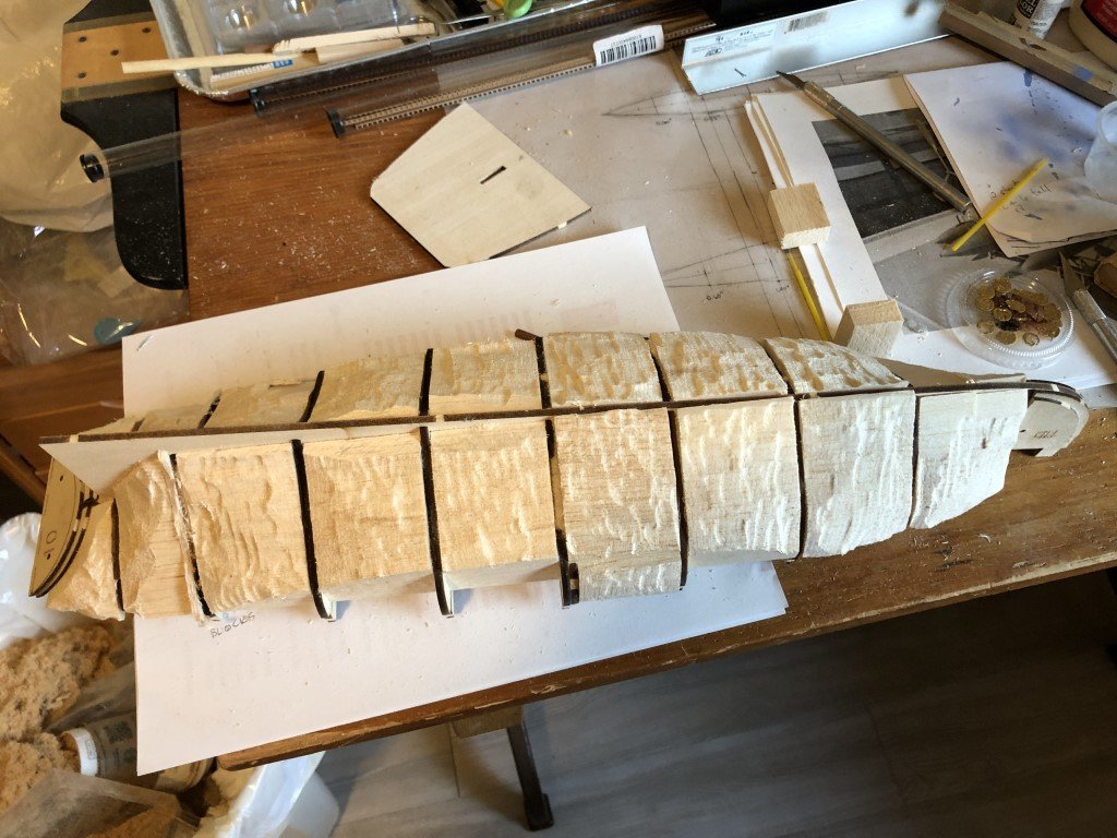
On my way to making this into a solid hull just like the original model! I've used some harder balsa blocks to fill in between the bulkheads. Here's a look after a Dremel sanding session! A couple more, smaller, filler blocks to add along the edges and then a couple to fill in the rest of the bow are still needed.
-
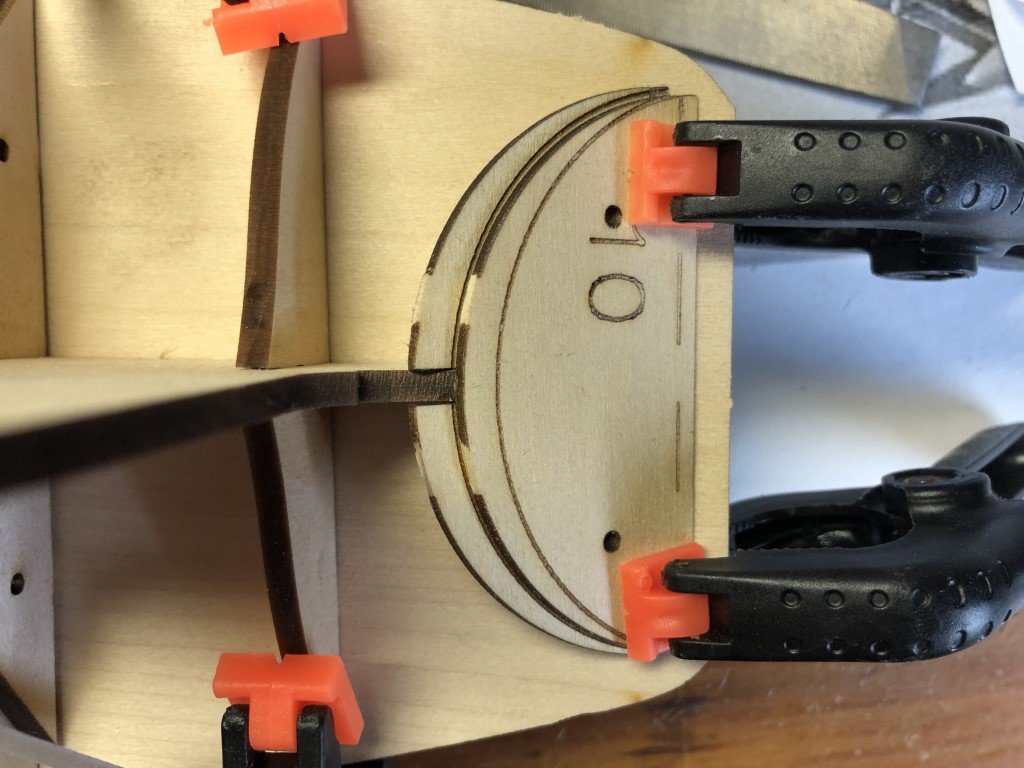
After making final check on bulkhead fit, bulkheads 1 - 9 and the corresponding support pieces were attached to the false keel. I brushed diluted white glue into all of the pre-aligned joints. This works better for me than to put glue on the slots and then slide the pieces back together. I also added the provided bow fillers using the toothpick alignment holes. Finally, I glued the two transom layers together. Then the structures were set aside to dry overnight. This morning I did some work on the transom. First a bevel was sanded along the top. The laser cut pieces have lines to show were the bevel needs to be. In order to get the bevel as neat as possible, I sanded the transom on a piece of sandpaper attached to my work surface. This is one of those places were it is better for me to bring the work to the sandpaper, than the sandpaper to my work. I clamped the stern deck to the false keel / bulkhead structure to check the bevel as work proceeded. Once satisfied, I glued the transom to the false keel - but not the transom deck, using the back of the transom deck for alignment aid. Now I will look for some filler wood to use between the bulkheads!
-
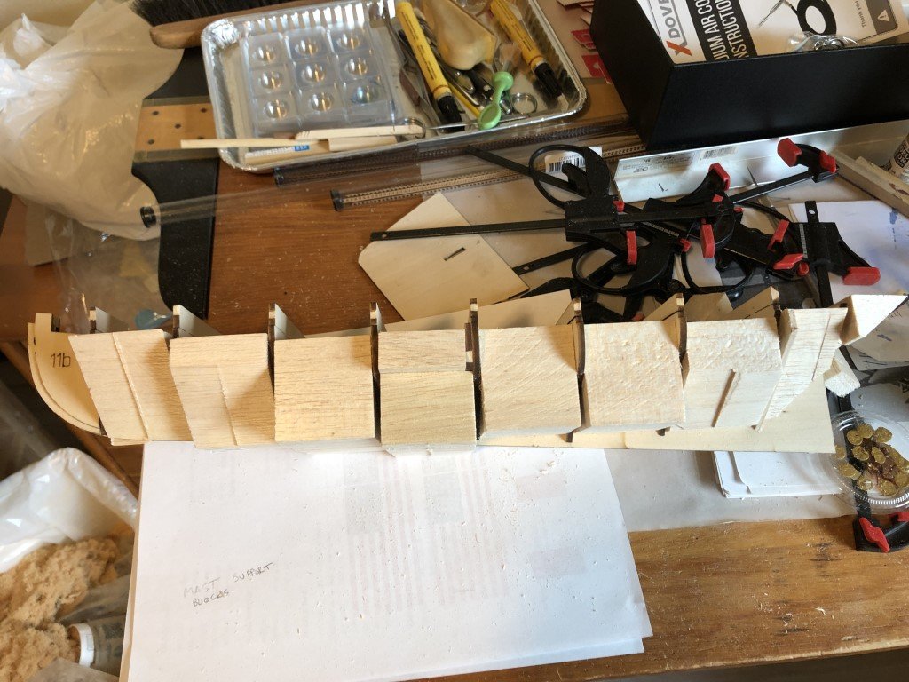
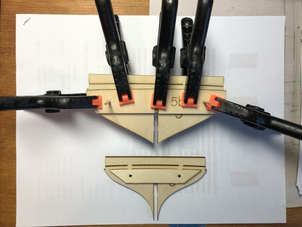
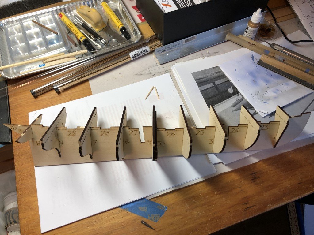
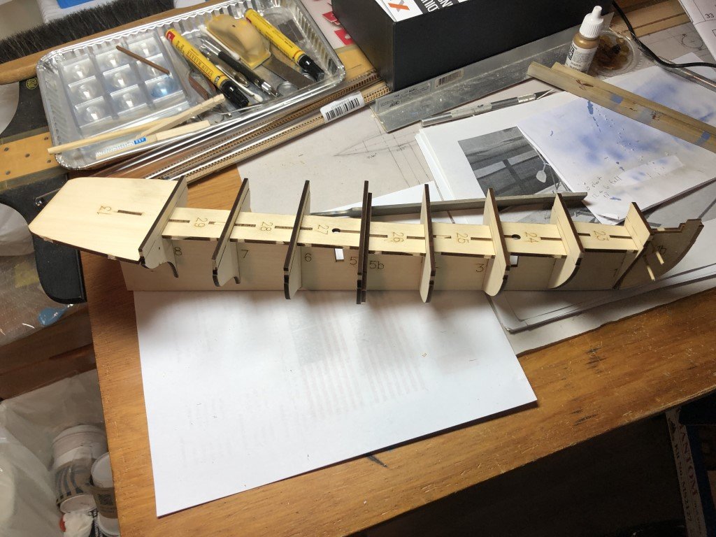
Released all the bulkheads and false keel. Two of the bulkheads (5 and 8 )have doublers to accommodate the decking. The doublers and bulkheads have alignment holes that make use of round toothpicks. This is a nice touch as even this size piece of wood likes to slide around when the glue is wet. Very little filing was needed to get the bulkheads to slide into place. I haven't worked with this type of wood for a long time and forgot how fragile it could be - when cutting out bulkhead 9, I accidently broke the piece along the grain near the bulkhead slot. The upper part of bulkheads 1 - 8 form a mould for the bulwark planking. After planking, they are removed. There are 'support pieces' 23 - 29 that fit between bulkheads 1 - 8. The support pieces do a great job in keeping the bulkheads square to the false keel. Nicely, they didn't take too much adjustment to have a good fit. Again I was a little too forceful and almost broke one of these in half. In the above picture, the stern deck (13) and bow filler pieces have been set in place. The bow fillers are made from two pieces (on each side) and have alignment holes. The instructions suggest beveling the bulkheads before attaching them permanently. The method shown is to lay a plank over the bulkheads to see what the bevel should be. Then take off the bulkhead, bevel some, and put it back in place to check with the plank again. There is a picture in the instruction book on a bevel being made using a Dremel tool - with the wood being so soft, my guess is that the chance of over sanding in this manner is great. A lot of kits will probably be damaged at this point. I will be taking a different tack. I think a better plan is to mark the location where bulkheads 6 - 9 end on the false keel so that the aft portion of the false keel can be reduced for the planking rabbet. Then the bulkheads and support pieces can be permanently attached. Next doublers for the masts will be added - these are not suggested in the instructions. Following this, some filler blocks will be added between the bulkheads - the limewood / basswood bulkheads are quite flexible and without support will not keep square when planking. I also feel like I can get a better hull contour and planking surface using filler blocks. So next up, preparations / strengthening for the hull shaping process.
-
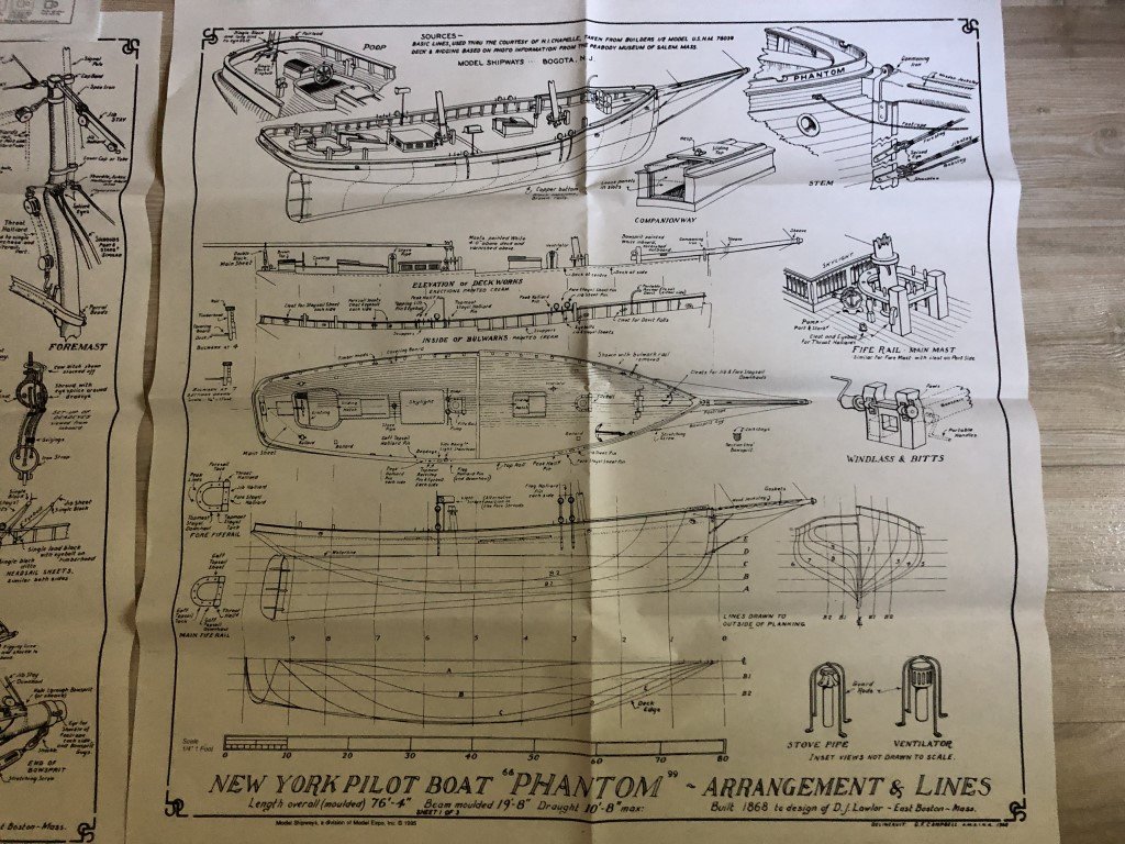
I've taken some measurements on the laser cut frames and it seems that they are reasonably symmetrical and inline with the cross sections on the enlarged plans. It looks like they will be fine to work with as is.
-
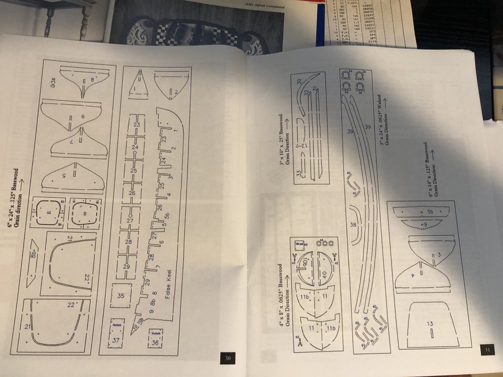
No, there is not a plan sheet with the laser cut pieces to scale. This is unfortunate both for checking the supplied pieces and for anyone that would have liked to scratch build based on a new plan set. It seems that this would not have been hard for Model Shipways to have printed and included. There are drawings of all the laser cut pieces in the instruction manual - but no scale is provided / it is not clear if there is any distortion in the drawings. They don't seem to be worth anymore than as part identification.
-
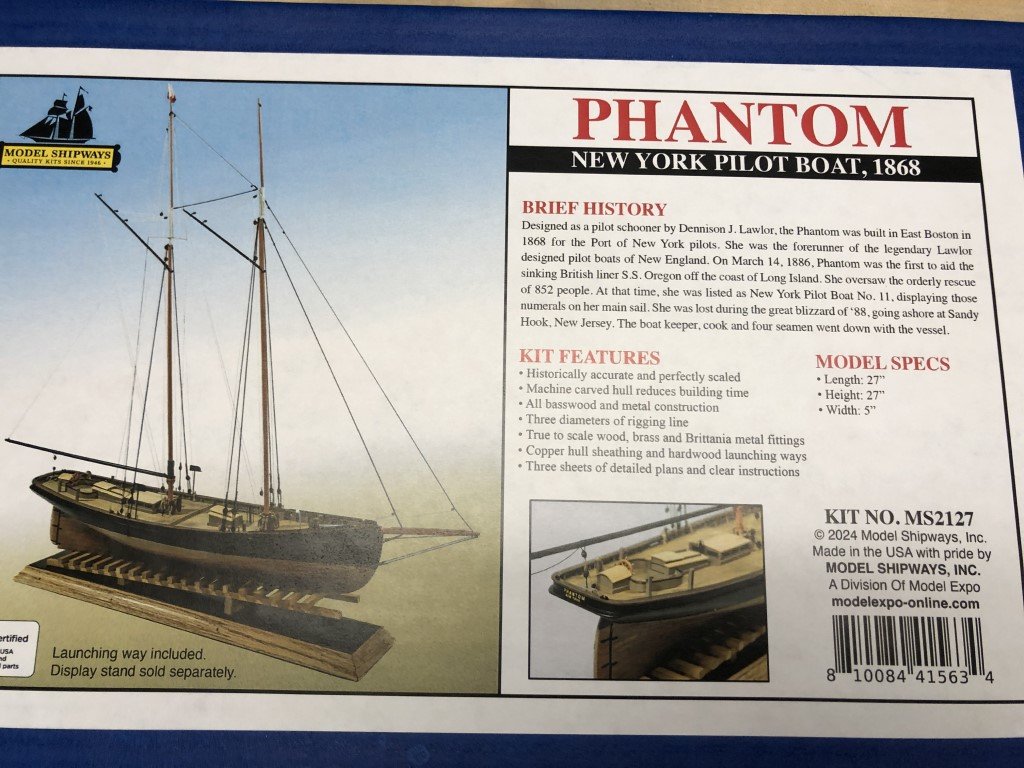
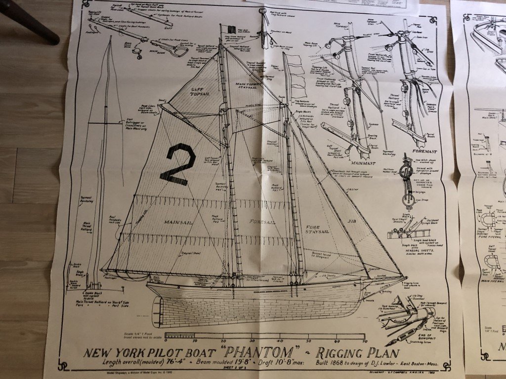
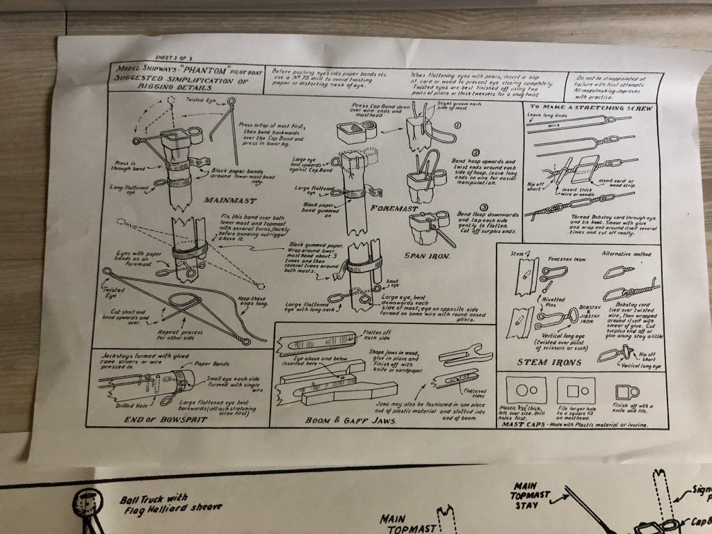
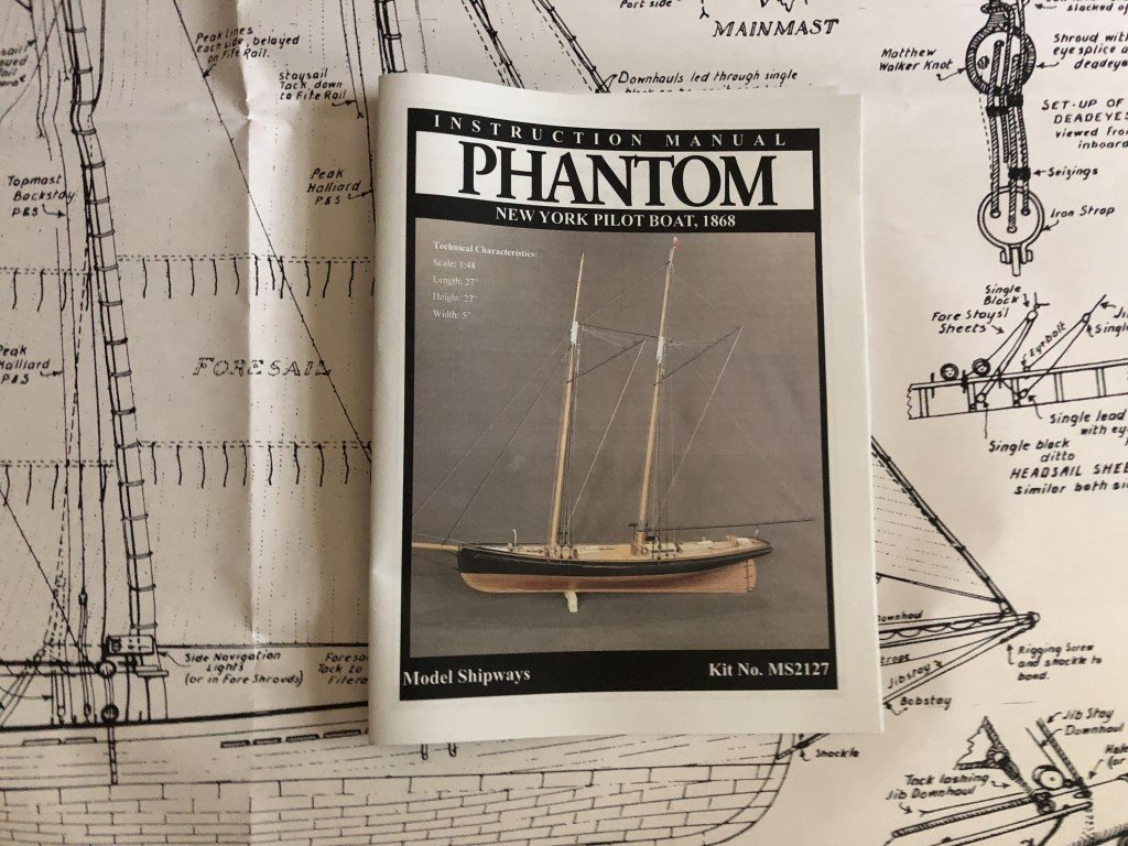
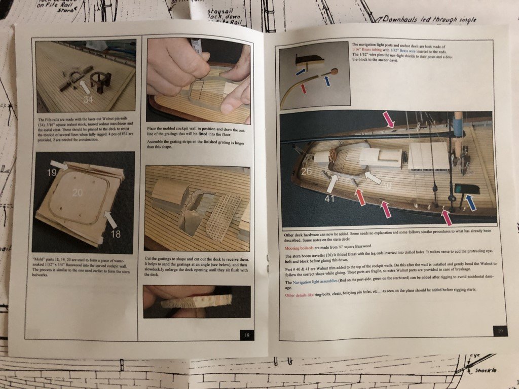
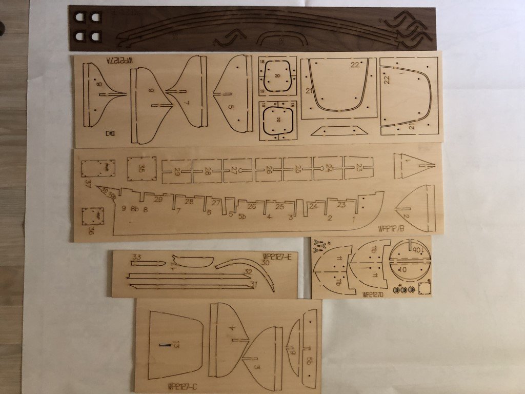
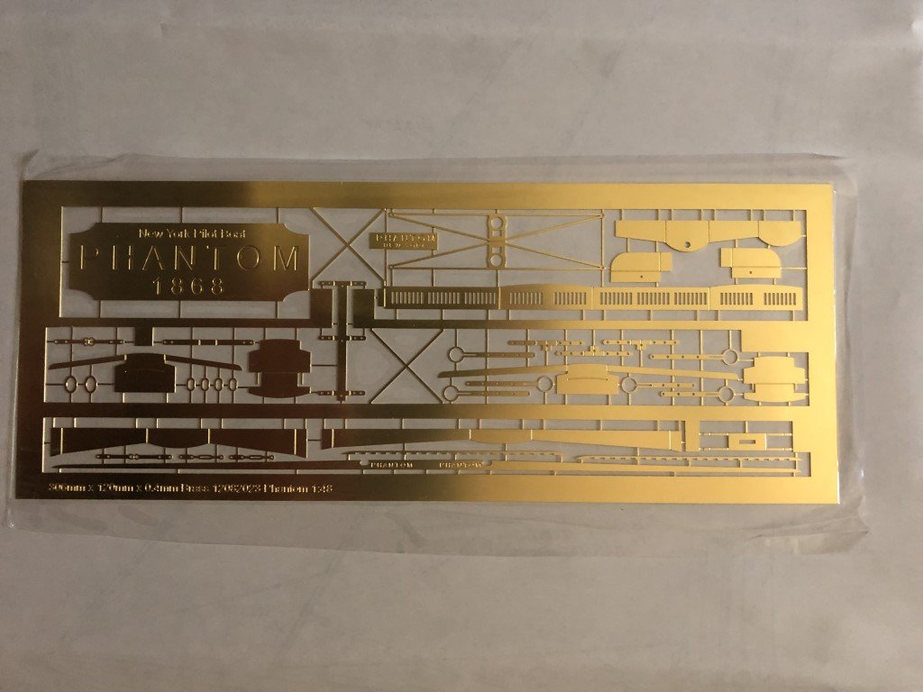
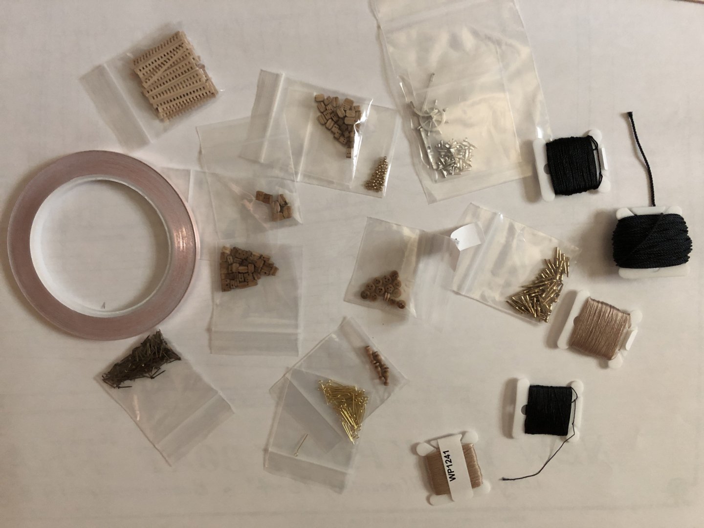
Today I received the newly released 1:48 scale Phantom New York Pilot Boat 1868 manufactured by Model Shipways. I wanted to build this kit for at least two reasons. First, in 2007, the 1:96 scale Phantom was the first wooden model ship that I completed (not the first I started!) and now after 17 years and many models I hope to do much better this time around. Second, I have a dog that I named after the boat and he is getting up in years - just turned 14 - so we don't know how much more time we will have with him. This model will help cement my memories of him. A young Phantom is the one on the left below; we lost Zargon, on the right, nearly 10 years ago. So back to the kit! As noted above, this is a reintroduction of Phantom at a larger scale. One of the biggest differences is that the new 1:48 version is plank on bulkhead; whereas the 1:96 version is a solid hull model. The plan set has not changed, short of making enlargements from the 1:96 scale kit. Thus if you have built the small model, there is really nothing new in terms of documentation. The instruction book for the 1:48 scale kit features color photographs to aid the construction process. It's sort of funny that Model Shipways continues to use the same basic material at the start of the booklet as they have for years. Once and a while they should update! For example in the Painting and Staining section, they still refer to making use of Floquil and Testers Model Master paints - both of which have been discontinued for years. Nevertheless, it appears that the construction is laid out in a thoughtful manor with many photographs to aid in the process. However, it won't be until the model is completed that I will really know how good they are (for me). In terms of materials, there is a slew of limewood strips and several sheets of laser cut materials: Note that the keel / stem / stern post components are separate from the false keel. This may simplify tapering of bulkheads and creation of the planking rabbet. There is a sheet of photo-etched parts. Some I will likely discard, e.g., the wheel and deck houses as they deserve to be built with wood. Finally, there is a collection of fittings, rigging line, etc. I'm not sure how much of this material will be used verses replaced. Certainly the blocks need to go and probably all the rigging material as well! Hopefully soon the construction will begin!

-
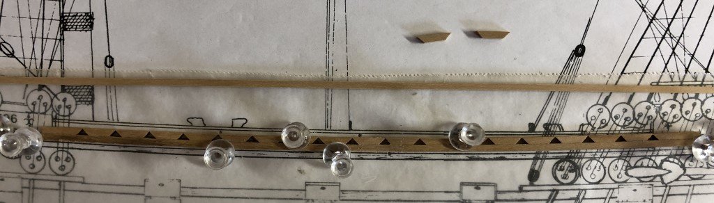
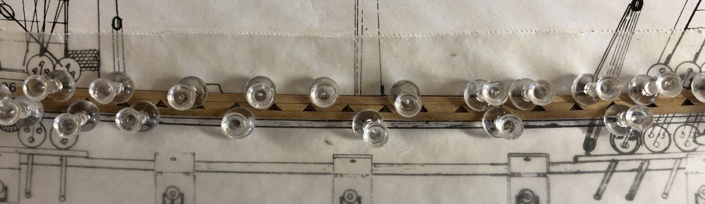
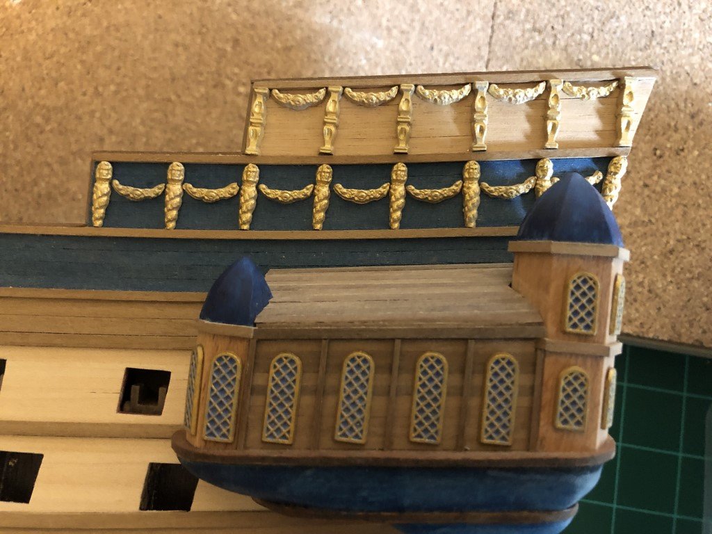
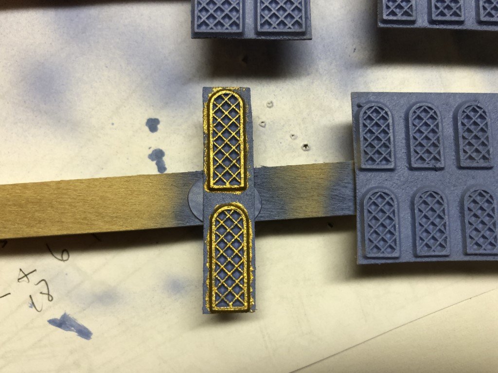
I've started to fit some of the decorations near the galleries. Most of the vertical ones are a tad too long and need to be shortened - which is fine as too long is better than too short! I'm reducing them quickly with a desk sander as filing was taking more effort than desired. I'll probably glue these in place later today. Currently I'm too caffeinated to keep everything in place.
-
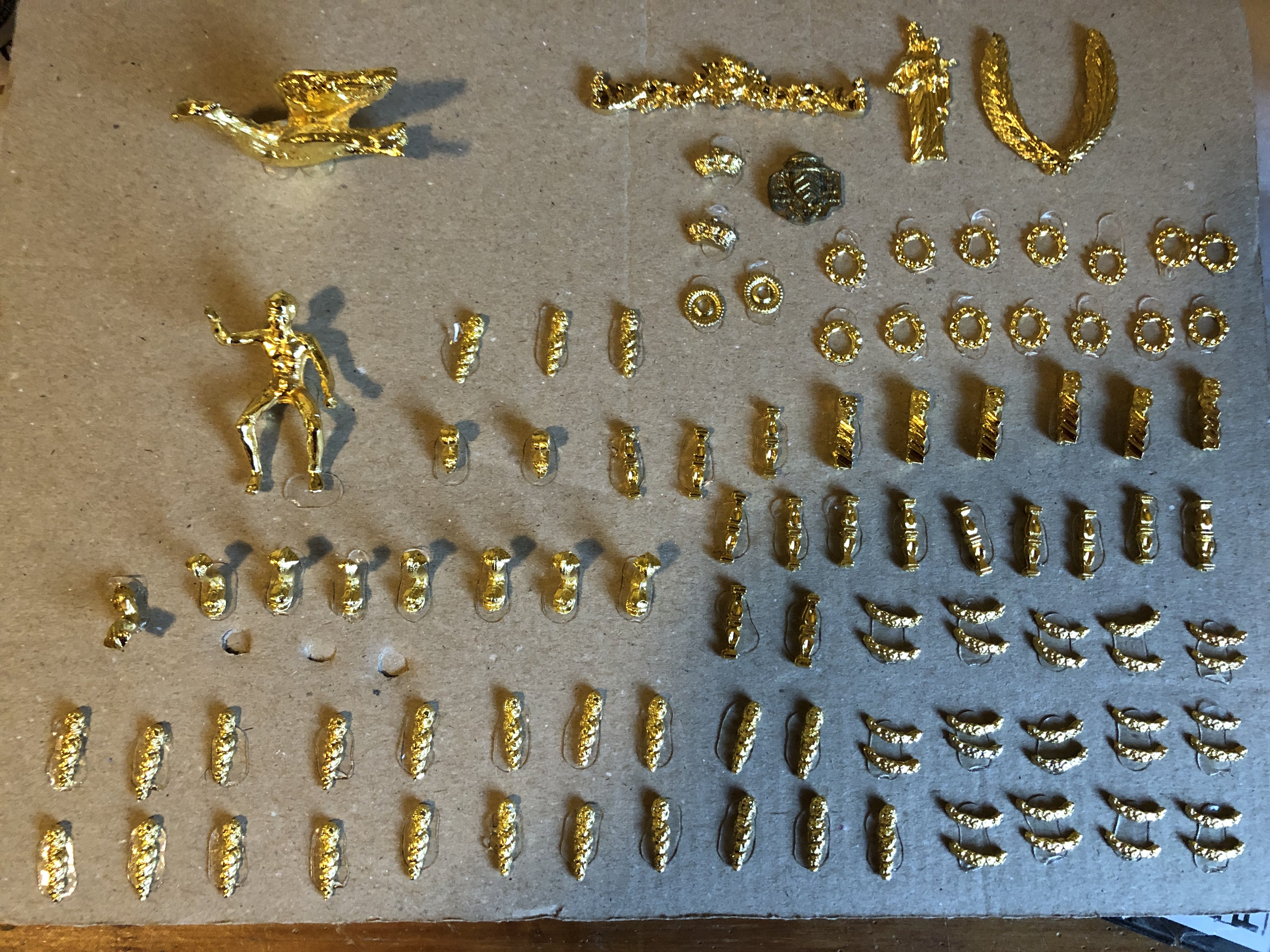
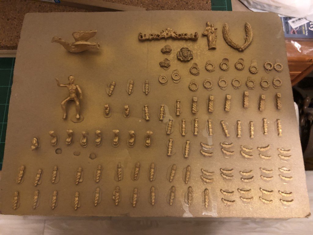
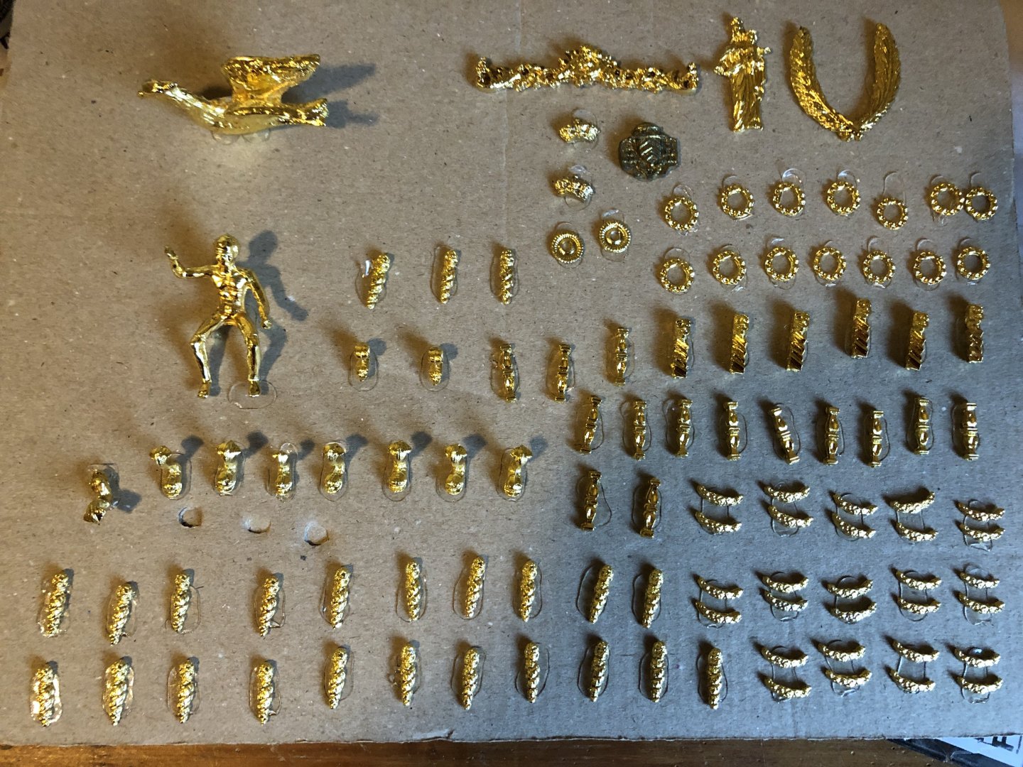
Now the castings have gotten a couple of coats of paint! Not quite as harsh as before. I used Vallejo Air Gold paint for this.
-
There sure are a lot of castings in this kit! I've 'stuck' the larger ones on a piece of cardboard so that I can airbrush them without too much fear of them flying away. I don't care much for the plating, so I will be toning them down a bit. Hopefully when done they will look more like they were gilded instead of plated. There are also a zillion flor de lis, but they are so small, I doubt that painting in this manner would be worthwhile. I will say that these Corel castings are not badly done compared to some other kits, especially when it comes to flash removal - nearly none needed here.
-
After months of having this model sitting on a shelf, I finally added the 6 ship's boats and the anchors. The ships boats are not as good as I had envisioned, but will do. I decided to paint them all a color similar to the hull planking and then stowed them upside down. I'm taking some 'artistic liberty' here, as the actual boats were probably white at this time and stowed upright as the ship had a significant davit system for the boats. Here again I choose not to include this detail. I'm going to call it job done as far as the model goes. Time to build a case and get this out of the house!
- 123 replies
-
- 7
-

-

-
- Le Pourquoi-Pas
- Constructo
- (and 1 more)
-
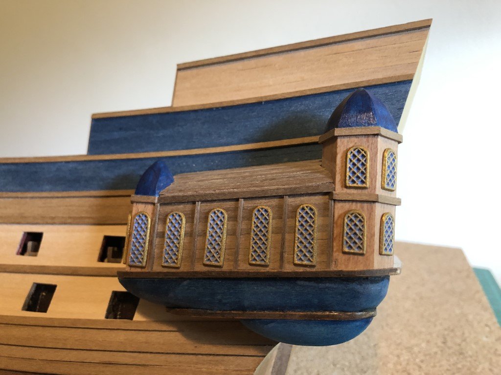
After a bit of touch painting, the windows have been installed:
-
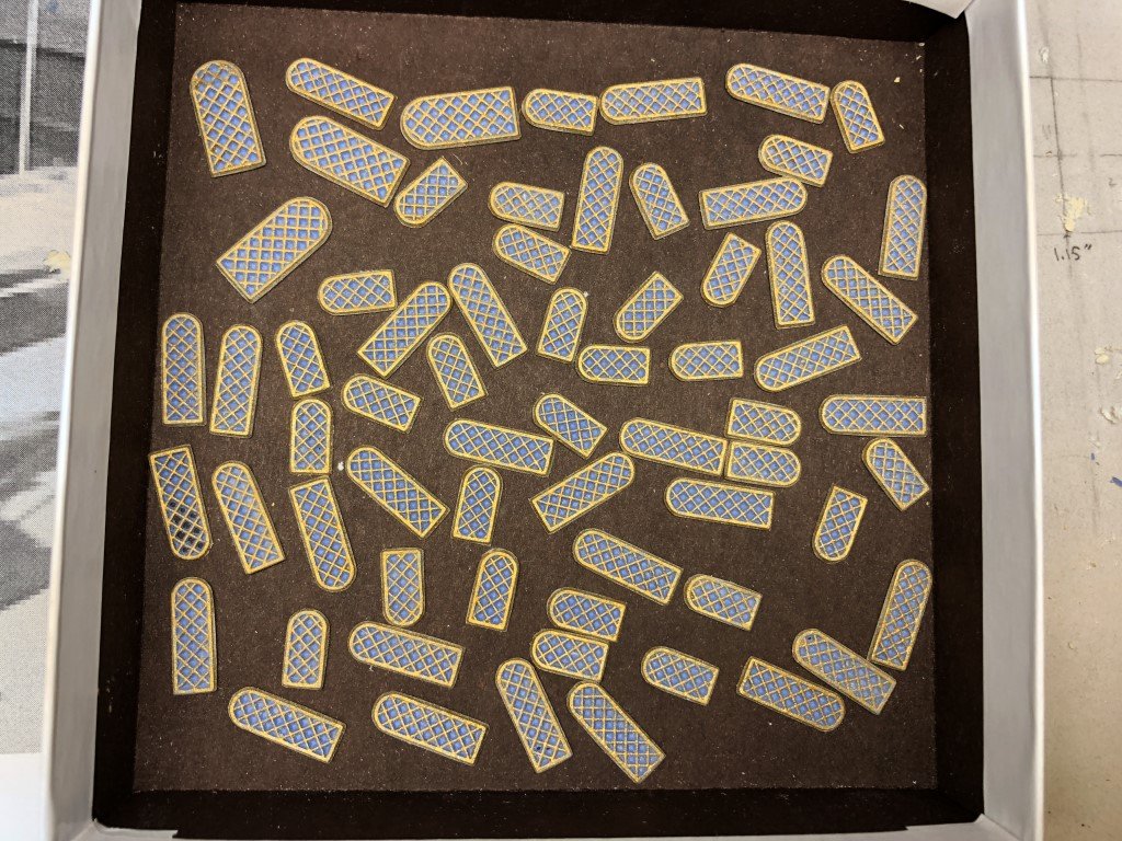
Got them all cut out / cleaned up today. Two or three have a bit of damage, but they will not be needed as there are extras of the tall and short narrow windows. There are no extras of the larger stern windows - fortunately they are all usable. The outer window casing edges need to be repainted and then the windows will be ready to install.
-
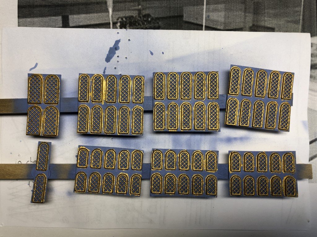
Can't quite believe it took 3 days to paint all the window grates - hard on the eyes for me! Now its time to start cutting all of the windows out. This may also be time consuming!
-
Thank you for looking!
-
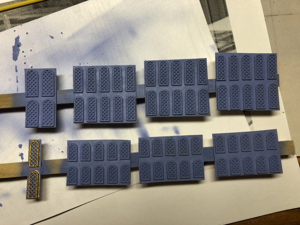
I'm planning to use the pressed fiber windows. Today I airbrushed the windows blue and am starting to paint the gratings and window frames by hand:
-
That is quite an 'interesting' looking machine! I just watched a couple of videos of it on the water - amazing! thanks Greg
- 288 replies
-
- 3
-
-
- Santos Dumont No. 18
- hydroplane
- (and 1 more)
-
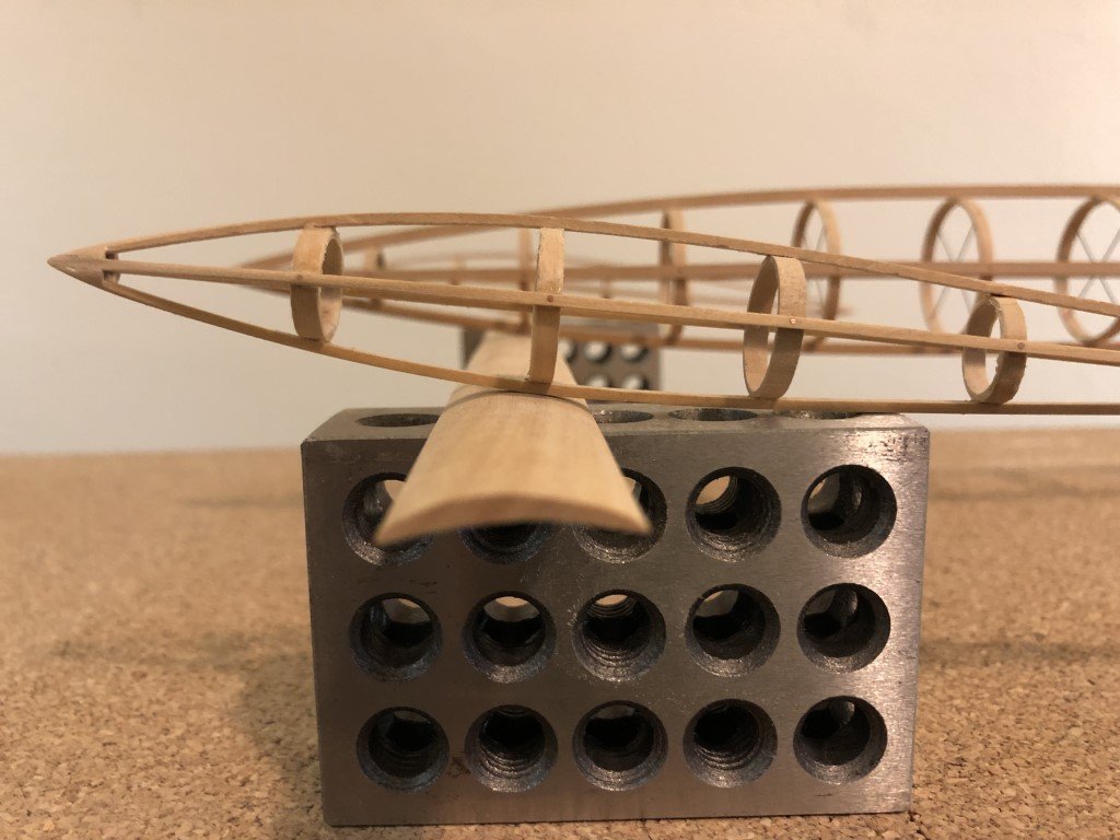
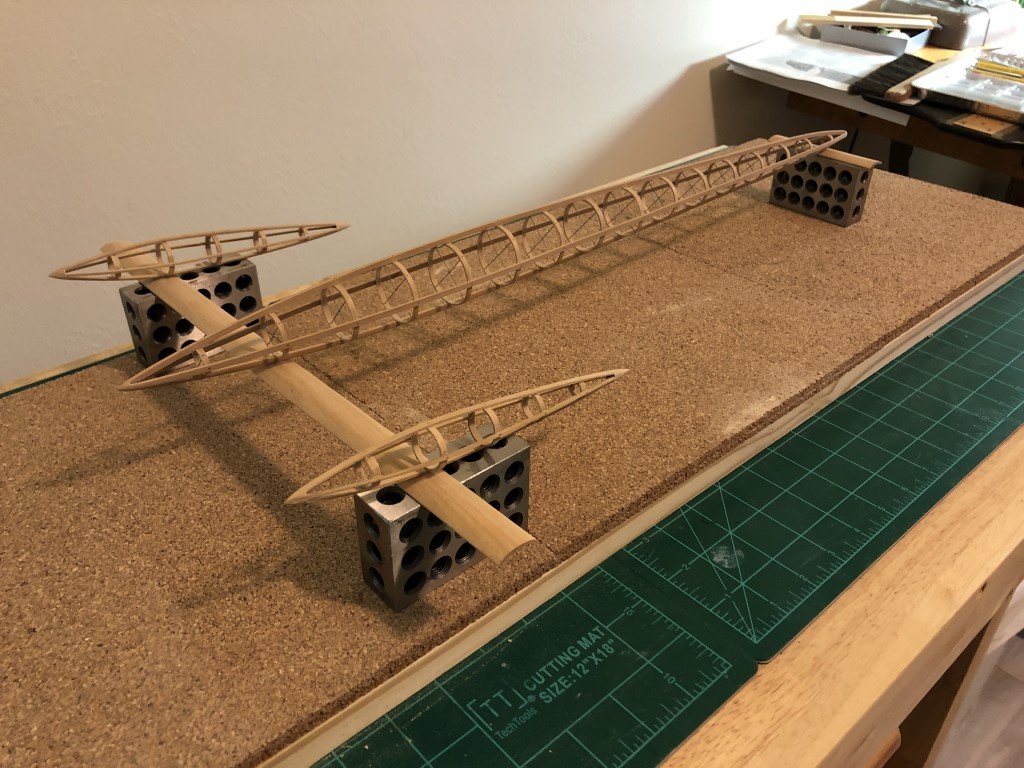
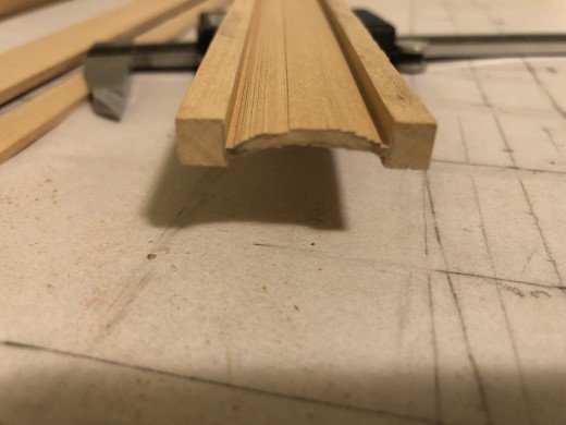
A couple of Dremel flap sanders later and some finish sanding has resulted in some good looking hydrofoils. Here is a mock up with the pontoon and nacelles. Now I really need to do some metal work!
- 288 replies
-
- 9
-
-
- Santos Dumont No. 18
- hydroplane
- (and 1 more)
-
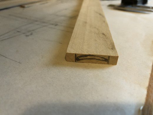
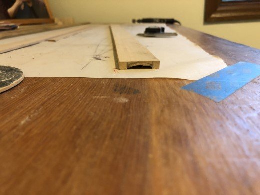
Decided to give a go on the hydrofoils today. I cut a piece of boxwood 1/4" thick, a bit wider than the chord (~ 2cm), and about 2 feet long. The main hydrofoil is about 15" long the rear one about 4". After marking the foil shape on one end of the slat, I repeatedly ran it across my table saw to 'mill' the basic shape. The extra width of the slat allows the slat to sit flat on the table saw for this operation. Now I will sand the final foil shape, except for the leading and trailing edges - they will be shaped after parting the mostly formed hydrofoil from the extra material. I hope this works!
- 288 replies
-
- 7
-
-
- Santos Dumont No. 18
- hydroplane
- (and 1 more)
-
Thank you so much for the offer! I really look forward to what you might be able to fill in the missing gaps from my kit. I do have the window frames (unlike you, there is no way I'm going to do all the work to open up and lighting he cupolas!), stern lanterns, and false cannon barrels. Greg
-
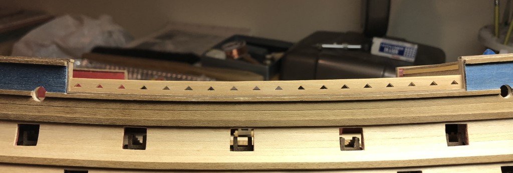
One triangular bulwark in place - one to go as well as the corresponding top rail. Seems to look better than what I could possibly do with the kit supplied pieces.
-
That's wonderful that you will take a look!
-
Got a good start on one of the triangular bulwark structures today. I've tried to build in some of the curvature. Once this is dry some finish sanding will even up all the pieces and will hopefully have a nice look.