
madtatt
-
Posts
278 -
Joined
-
Last visited
Content Type
Profiles
Forums
Gallery
Events
Everything posted by madtatt
-
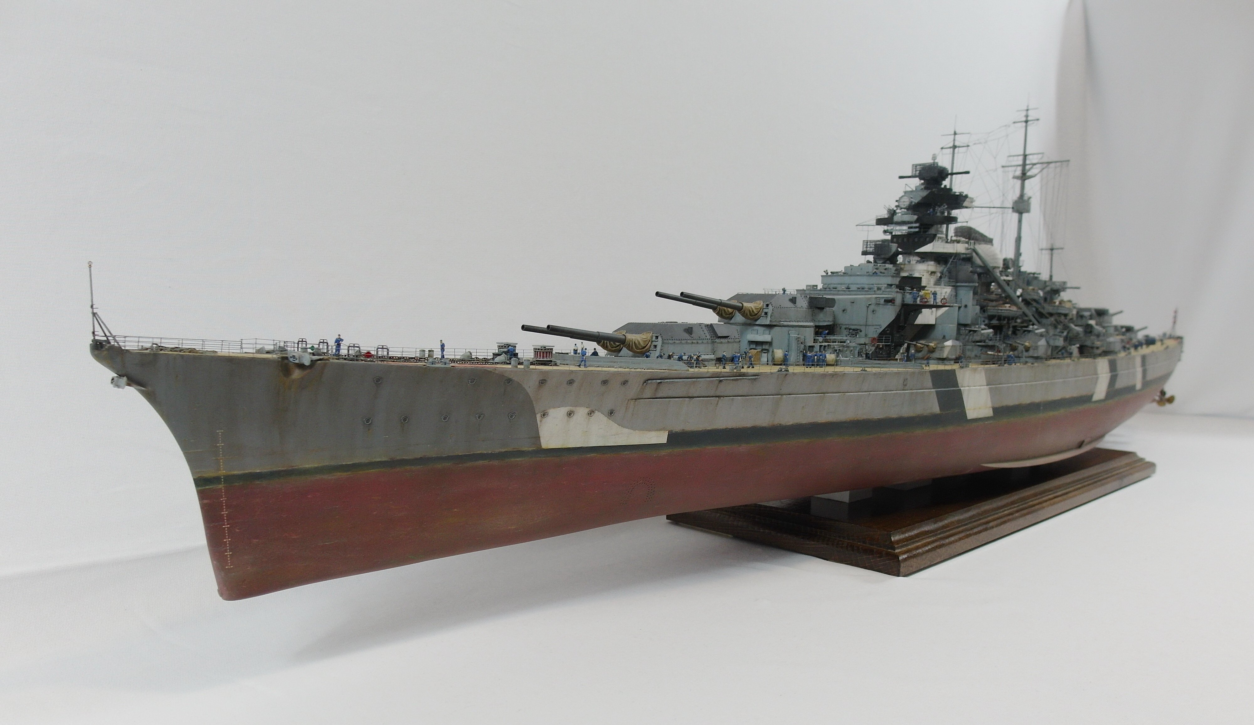
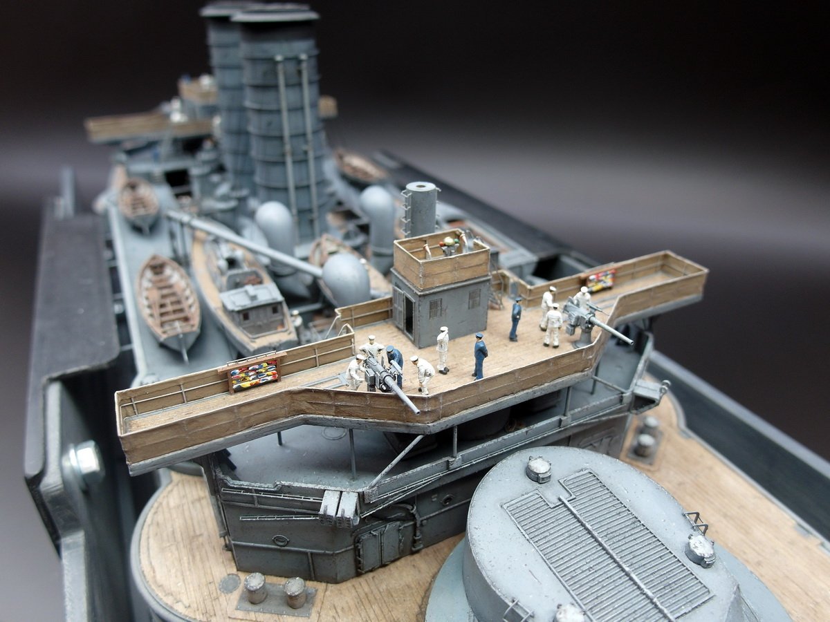
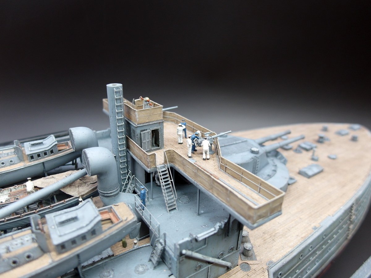
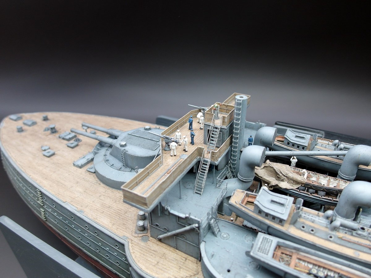
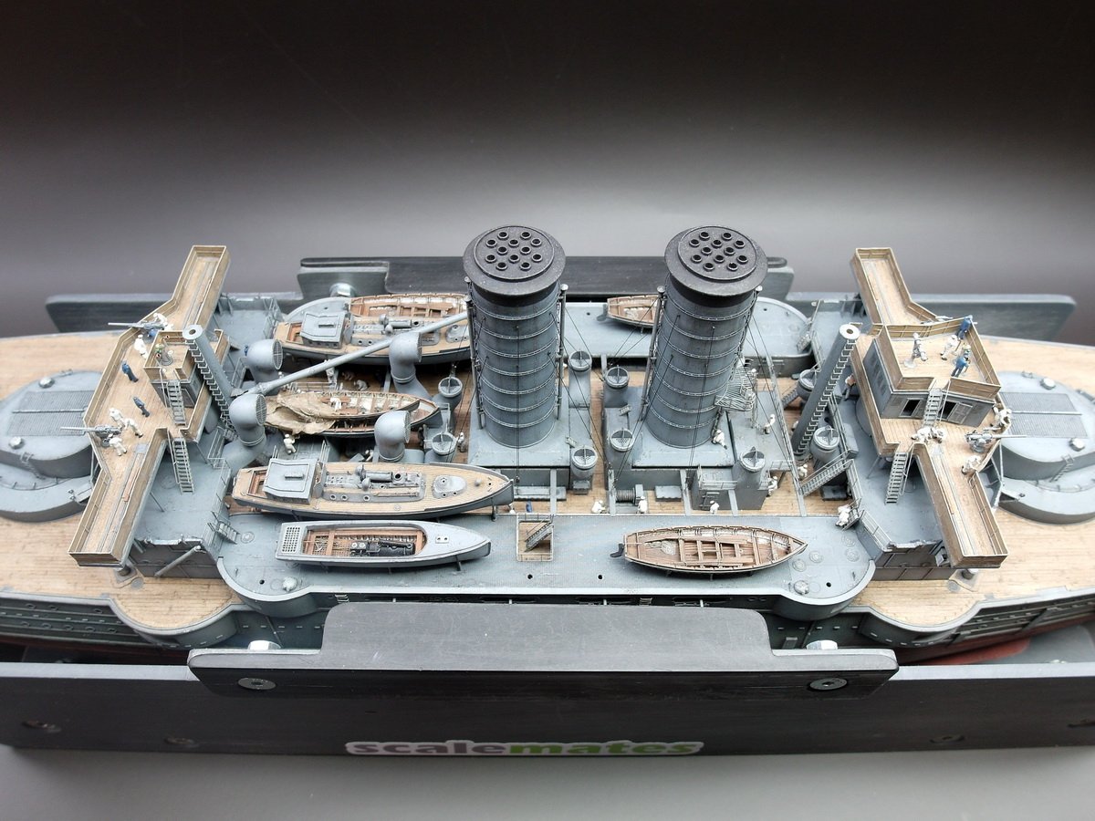
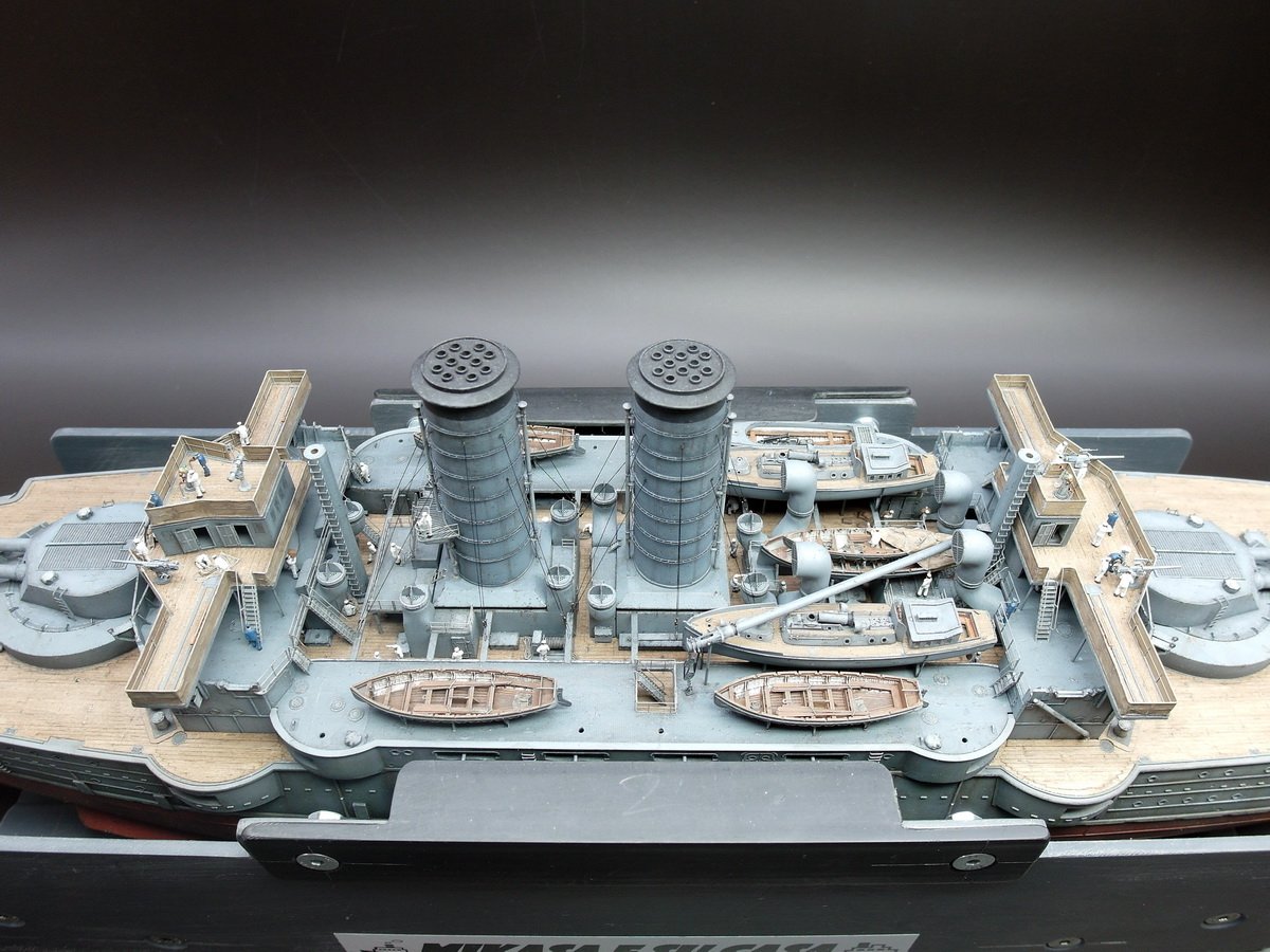
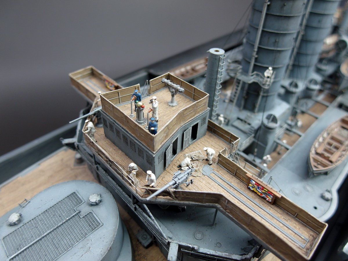
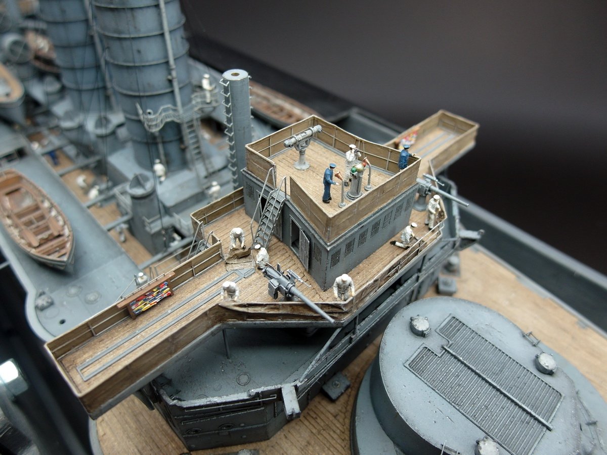
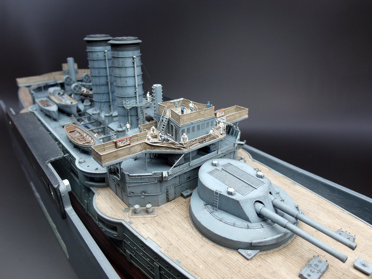
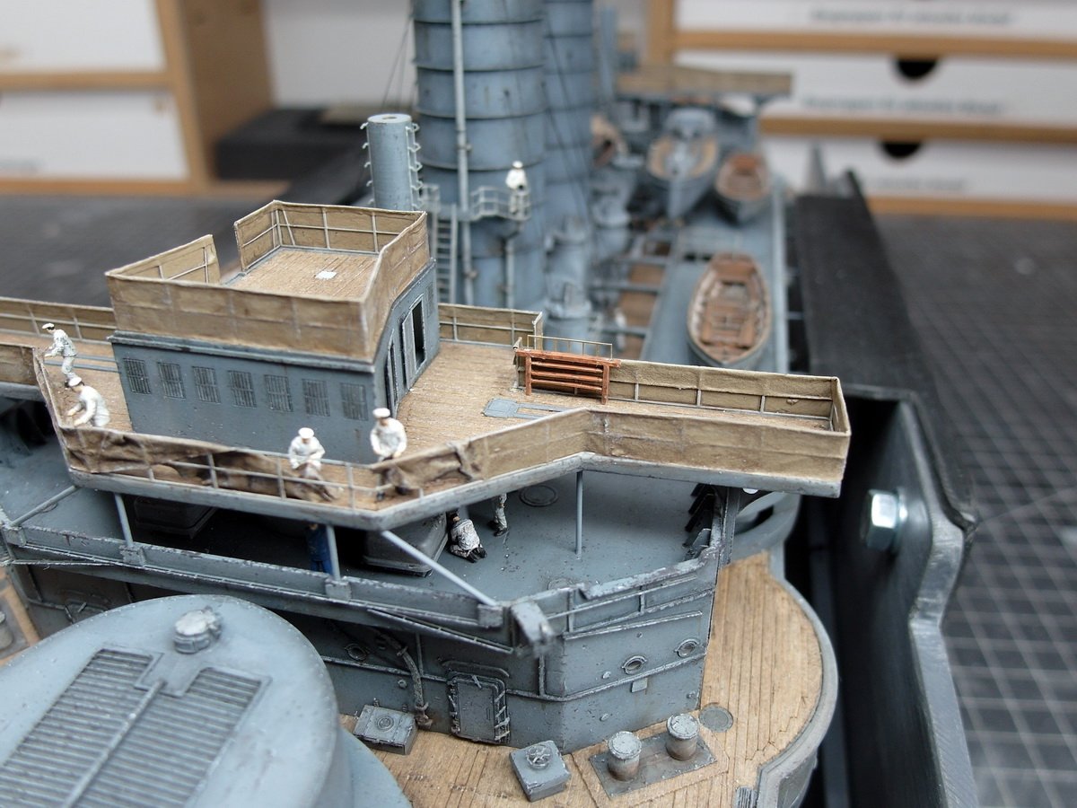
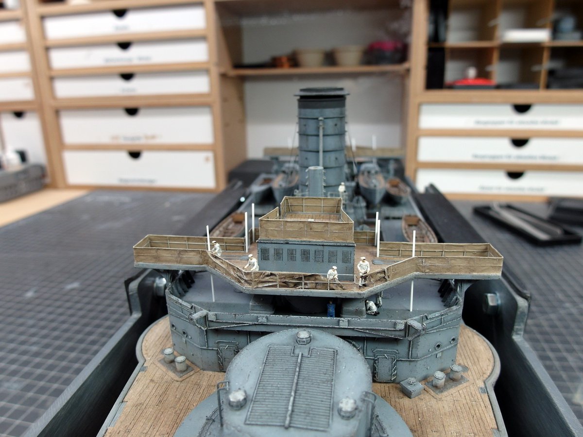
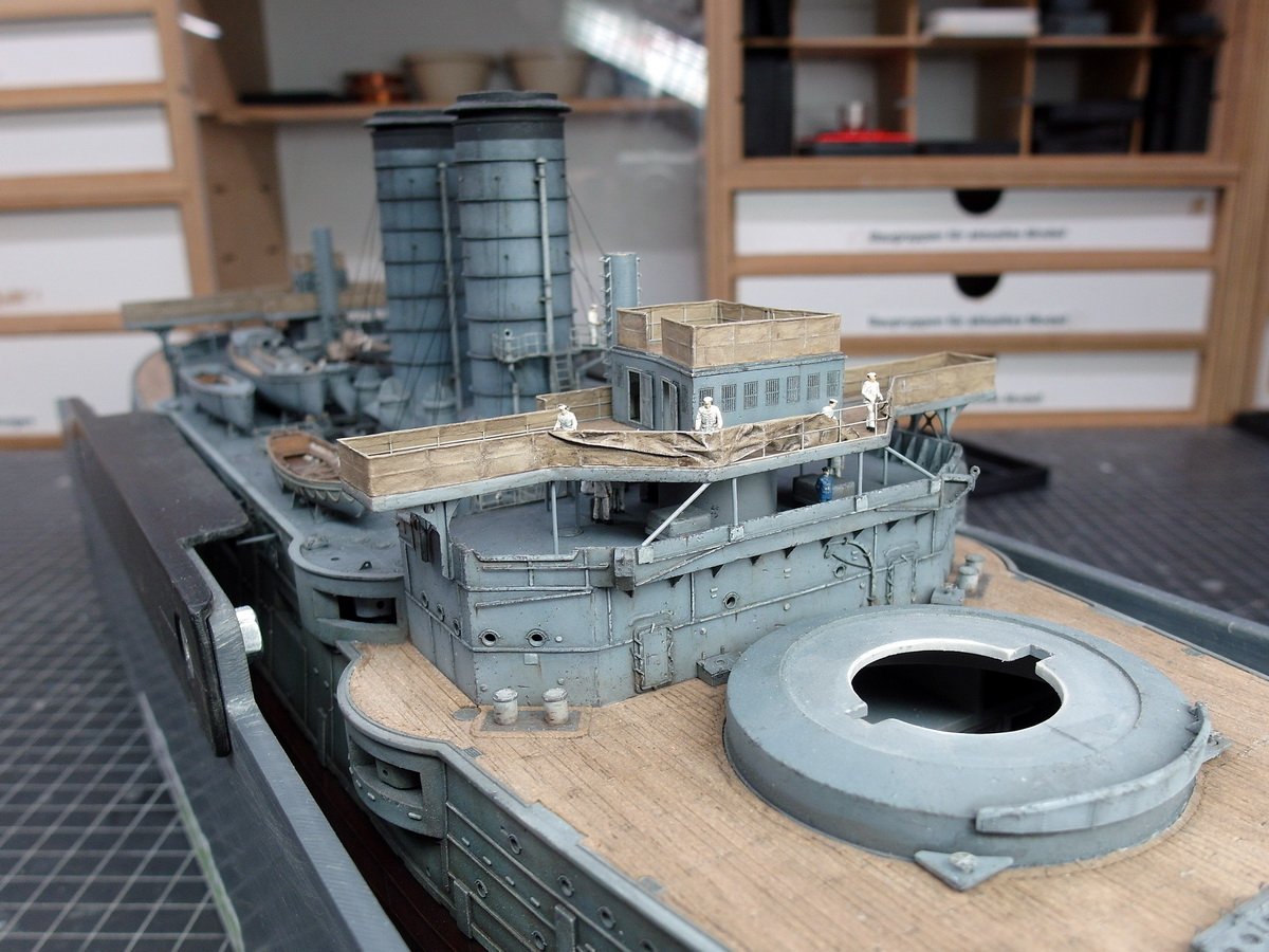
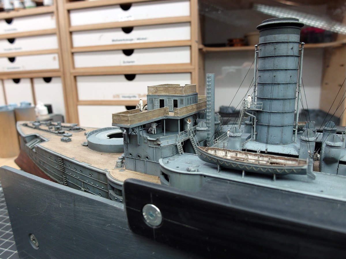
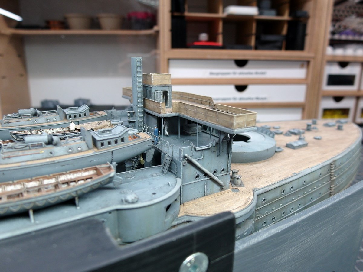
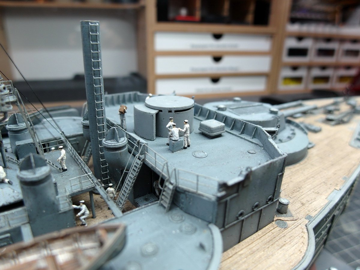
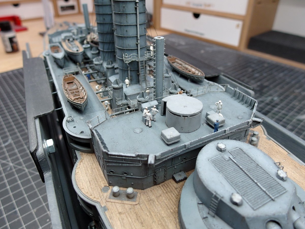
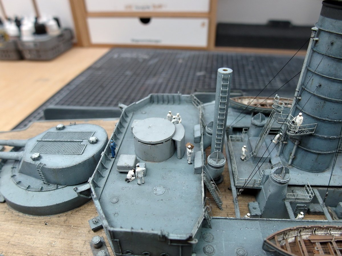
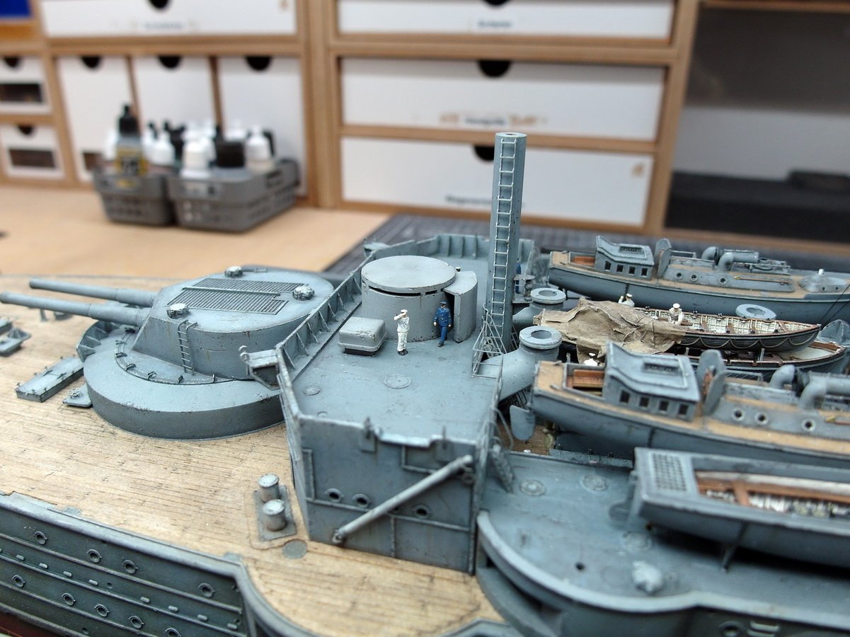
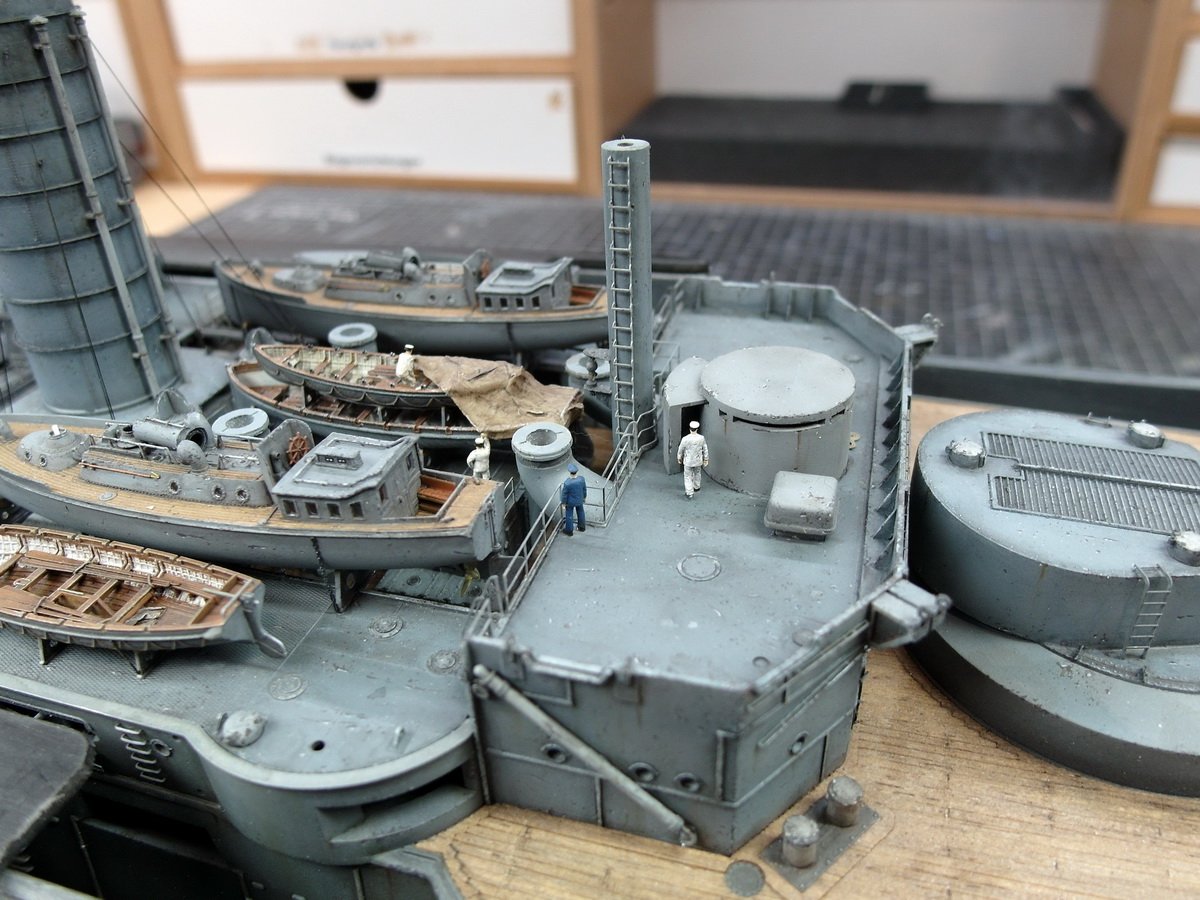
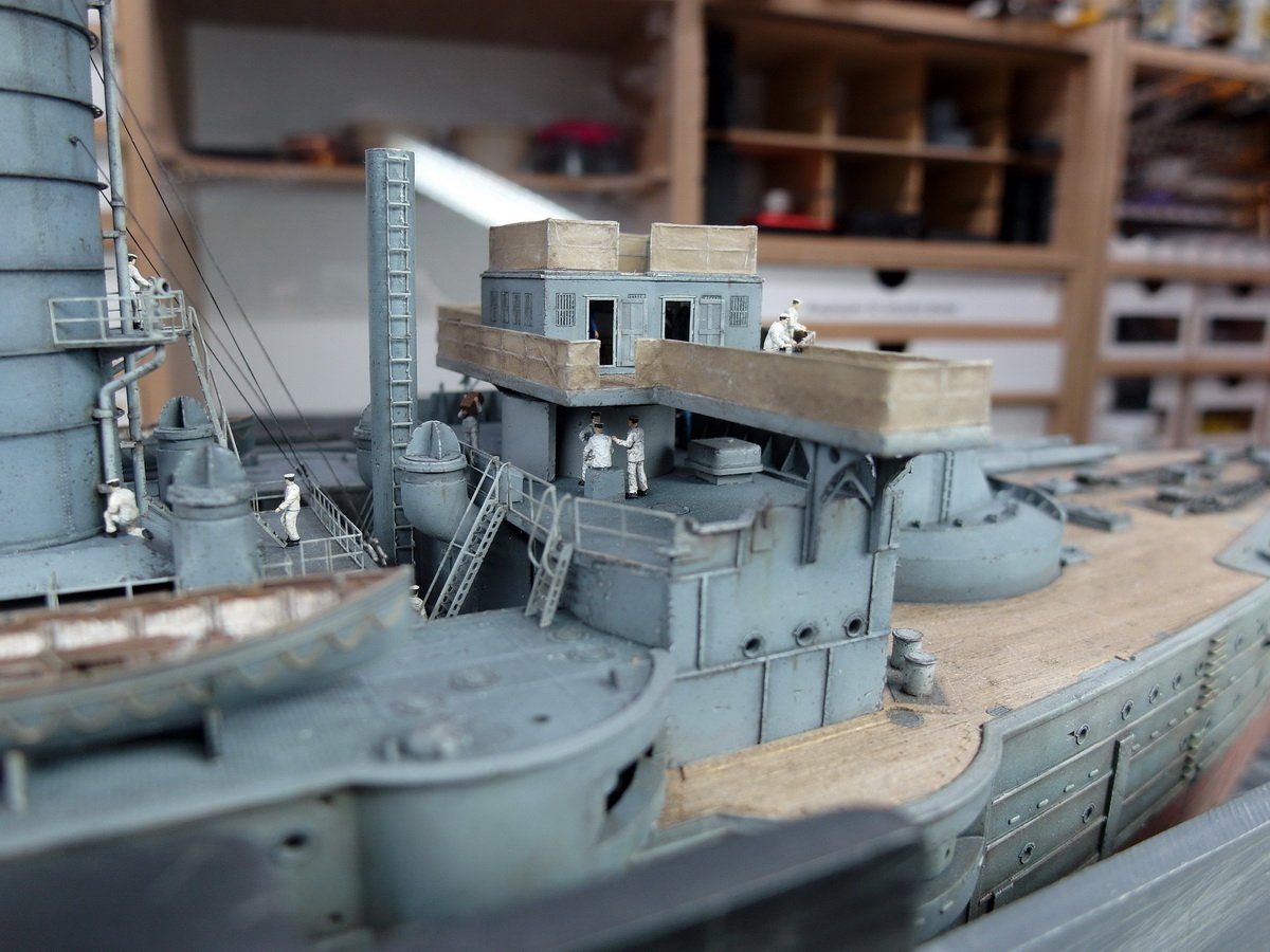
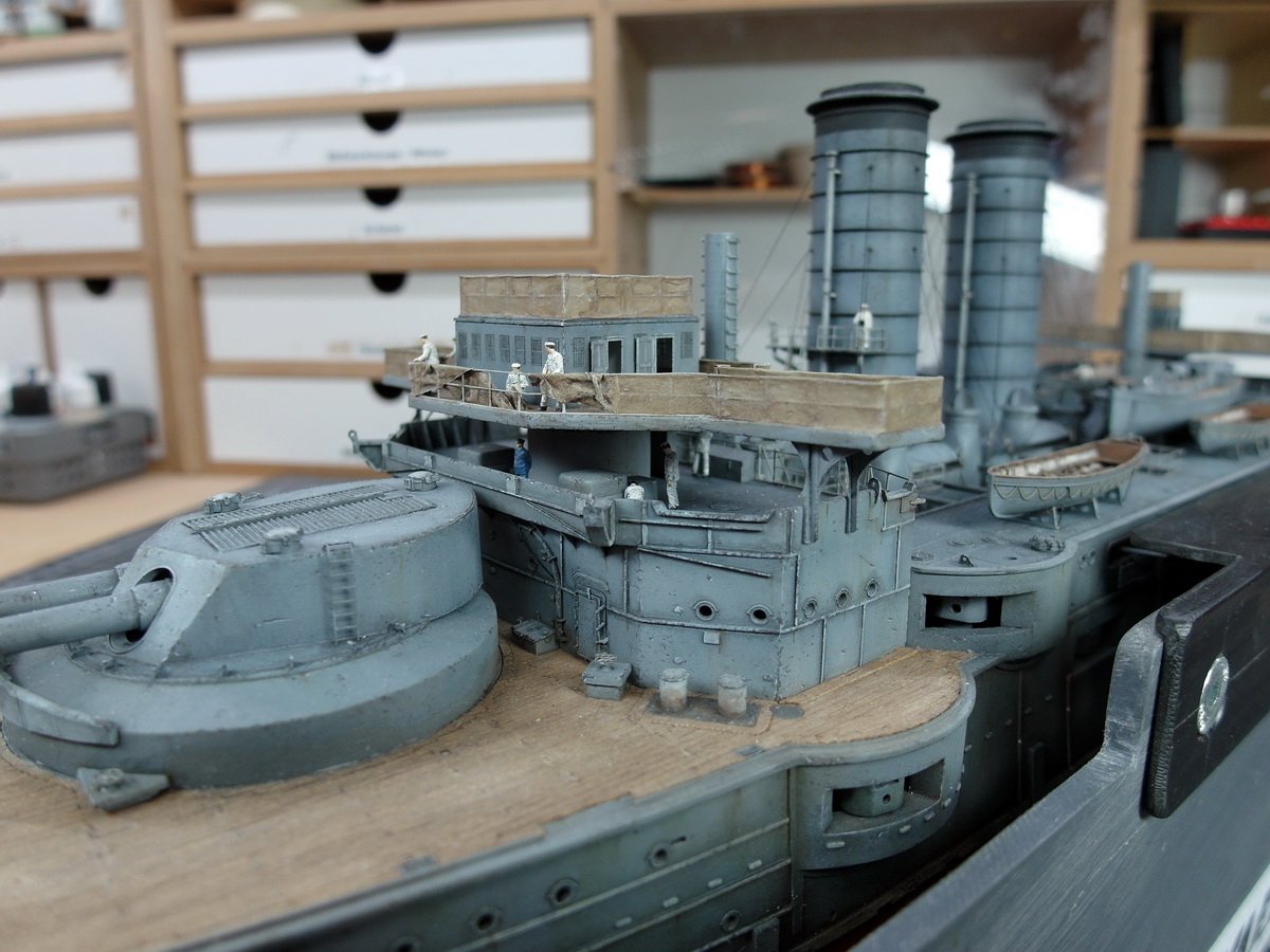
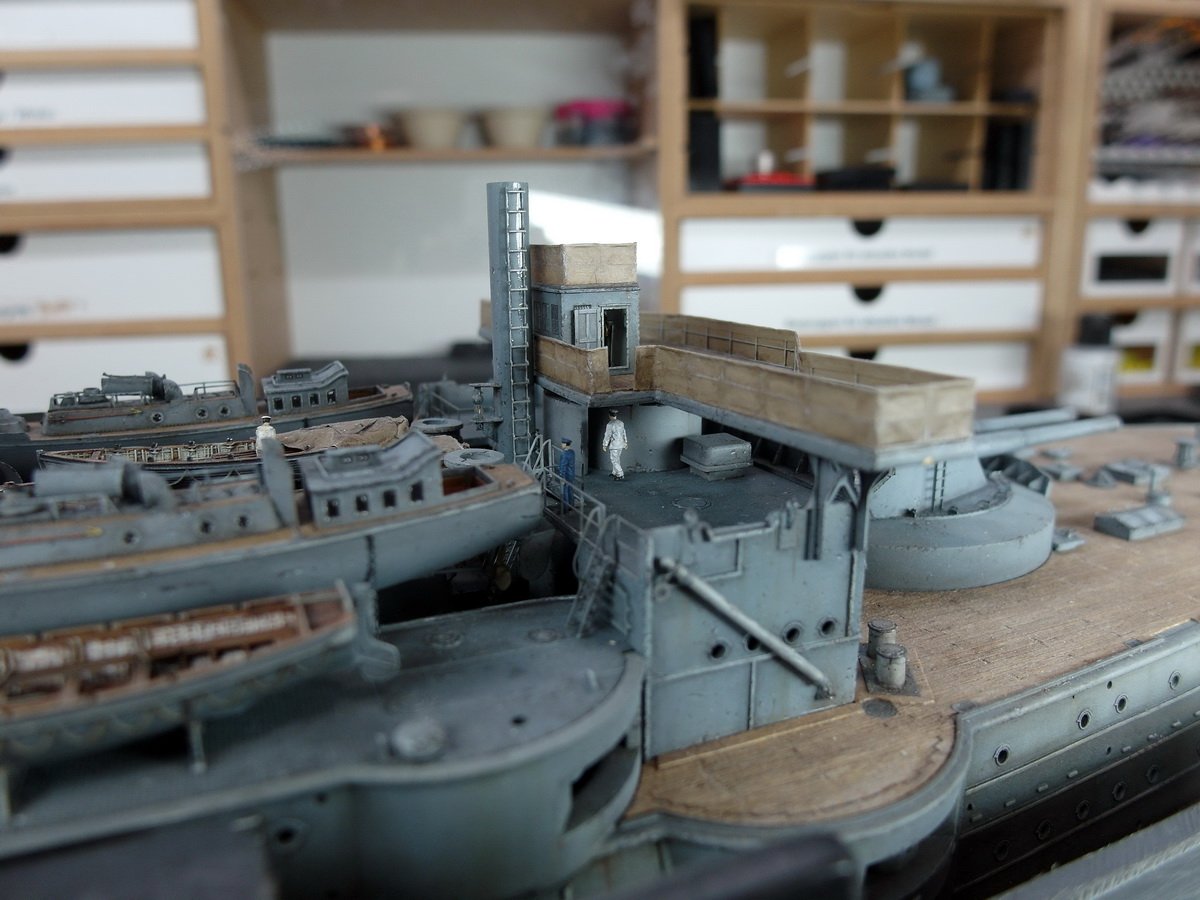
 Hello everyone. Just a few pictures of the aft bridge today. It's now been fitted with crew and interior details. The searchlights are still missing, as I'm waiting for the 3D print from New Zealand. Also, a signal flag needs to be hoisted, but for that I need the complete mast. 😁 It still annoys me a little that I didn’t show how to attach the tarpaulin here. But crying won’t help, so this is what I’ve done. The crew is being trained on the 12 pound cannons. Under the strict supervision of the officers. That means I’ve now finished everything amidships. As always, following my crafting maxim, I’m working from the inside out. And so I can now turn my attention to the bow and the stern.
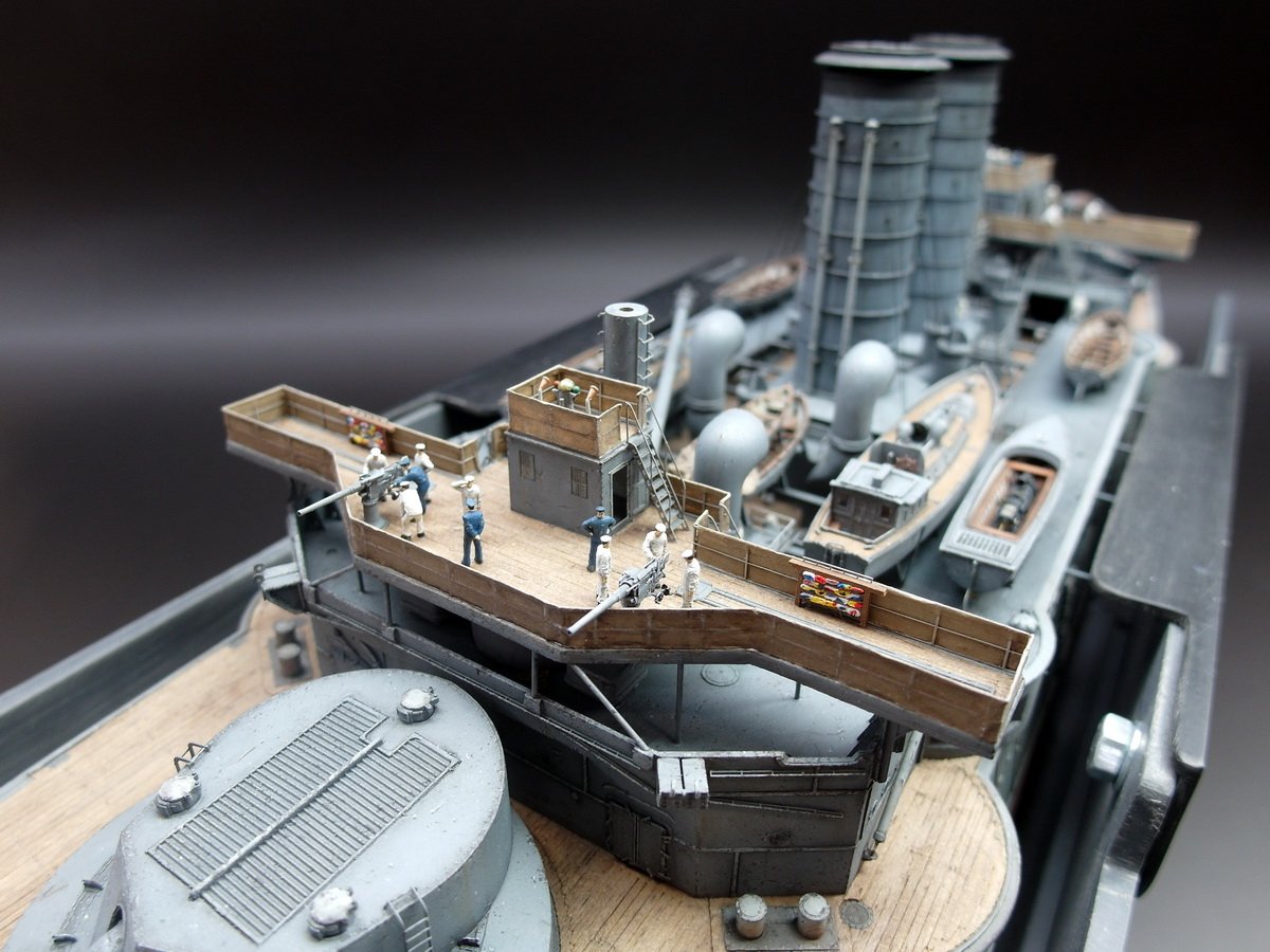
- 212 replies
-
- 3
-

-
- Russo-Japanese War
- Mikasa
- (and 2 more)
-
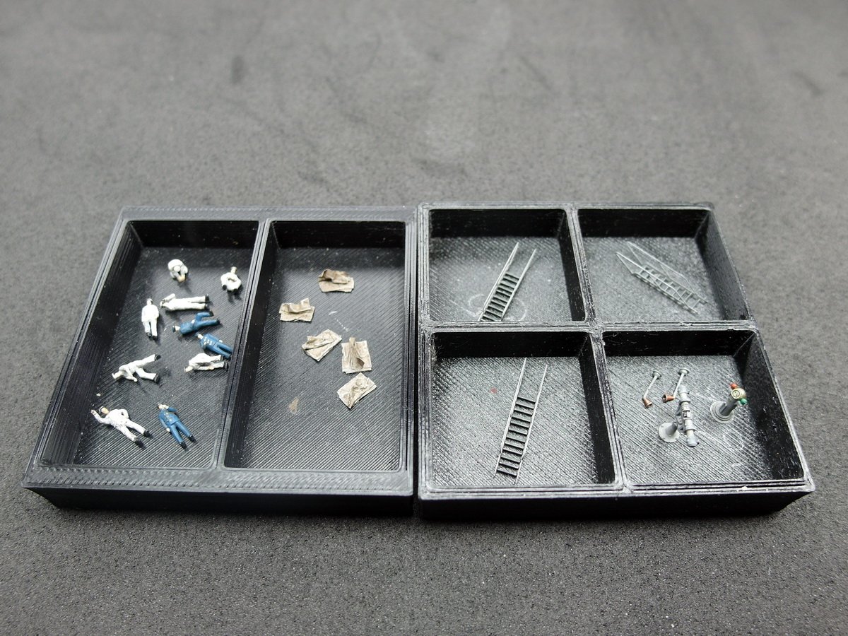
Okay, a quick update for the weekend. And here’s the material you’ll need. Curtain up: The crew folds up the excess tarpaulins for storage. An officer supervises the work from above. Finally, my compass, into which I had put so much work, could also be placed on the model. There’s not much to see of his brother in the wheelhouse. And the first 12-pound naval guns were also allowed to take their places. The front bridge is now complete, except for the searchlights.

- 212 replies
-
- 6
-
-

-
- Russo-Japanese War
- Mikasa
- (and 2 more)
-
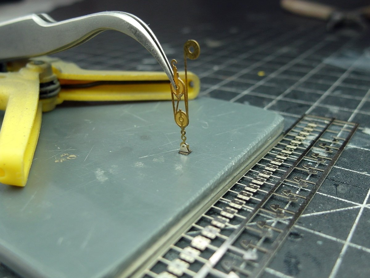
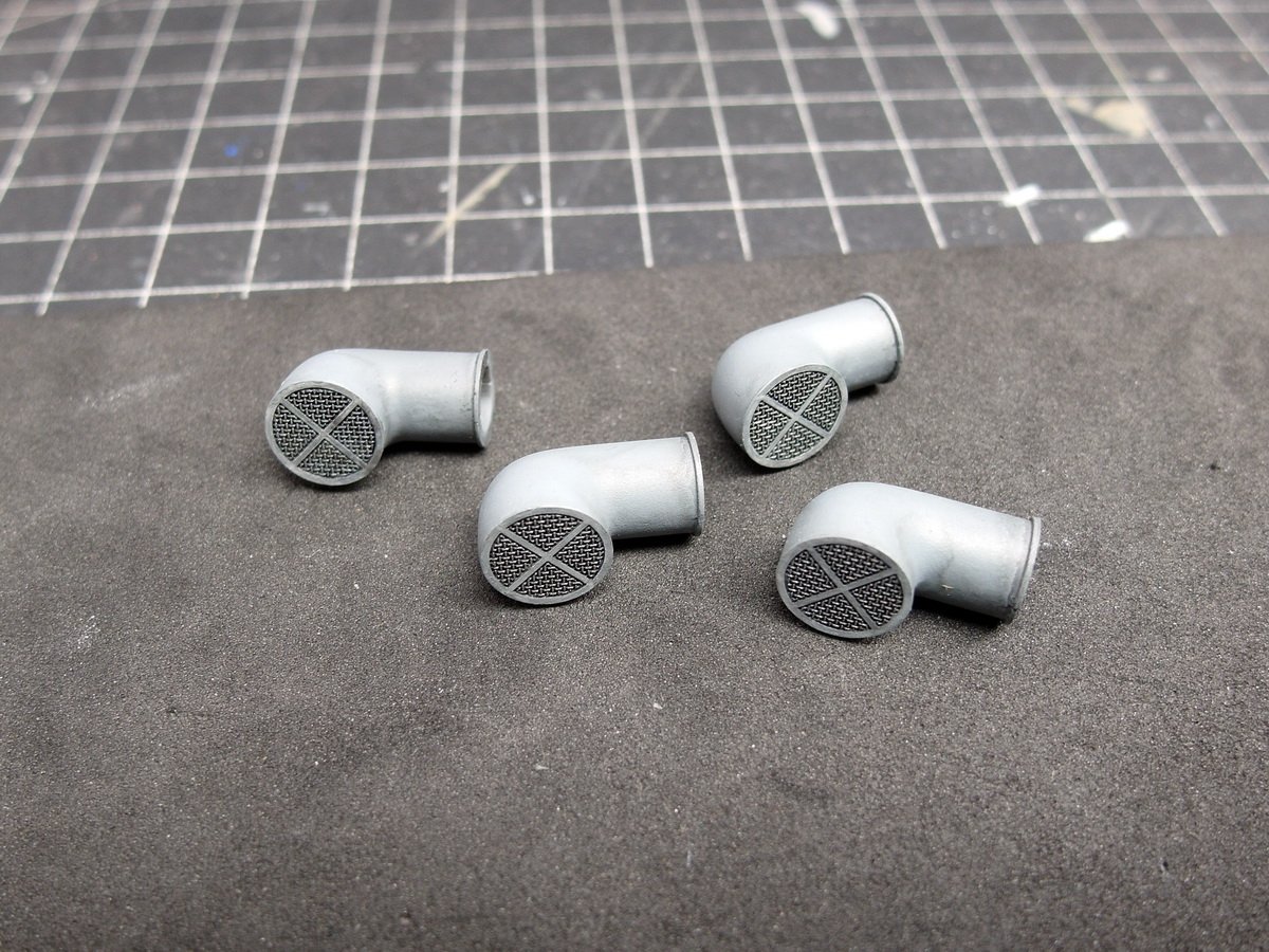
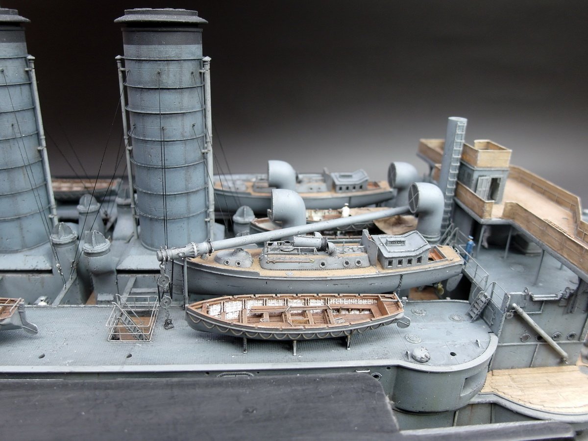
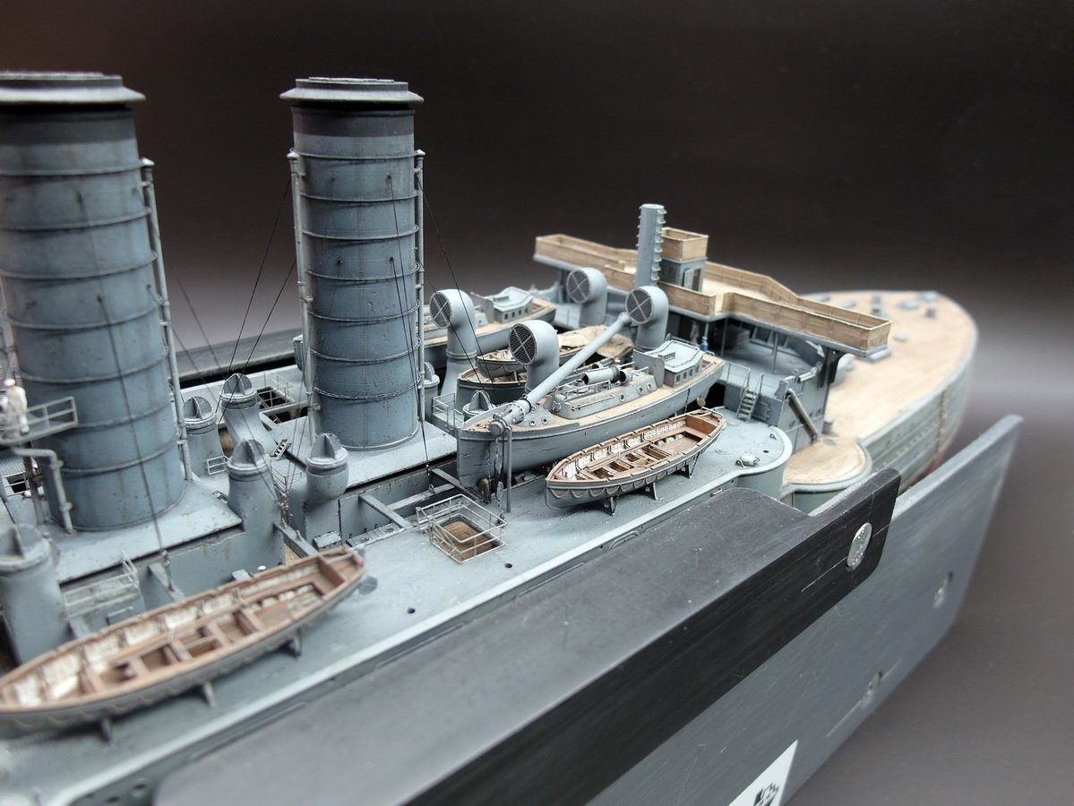
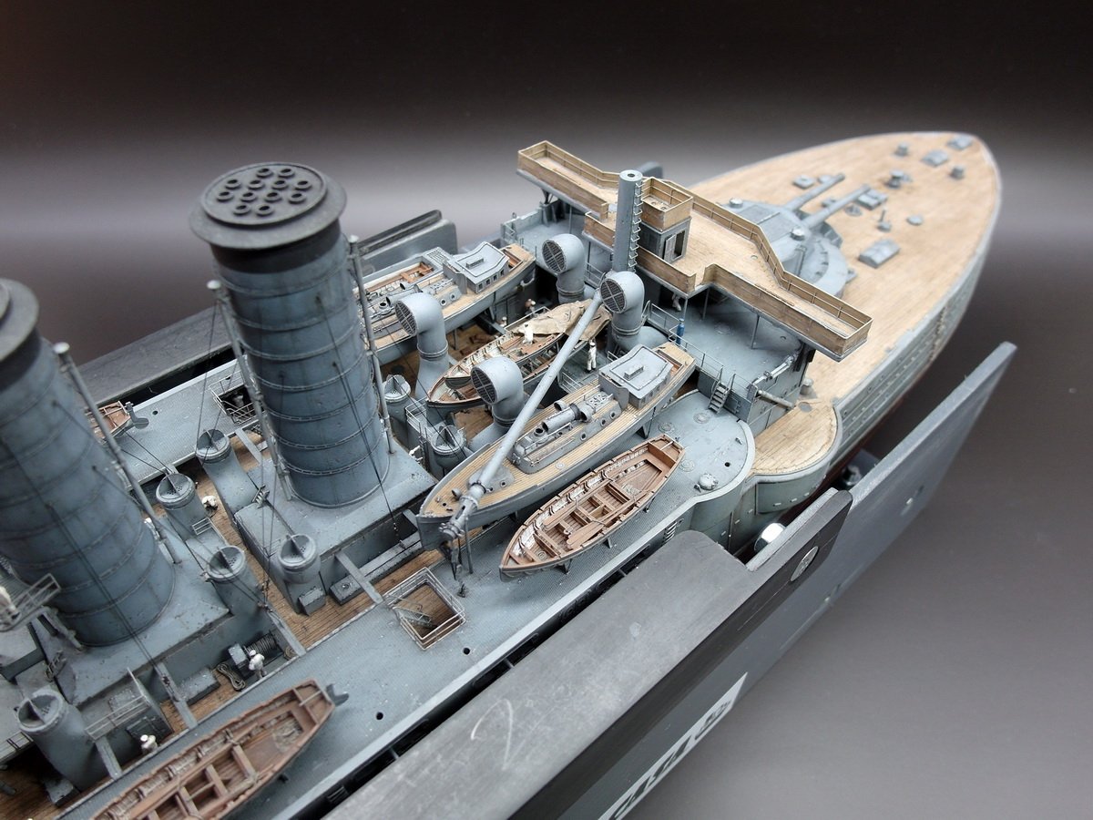
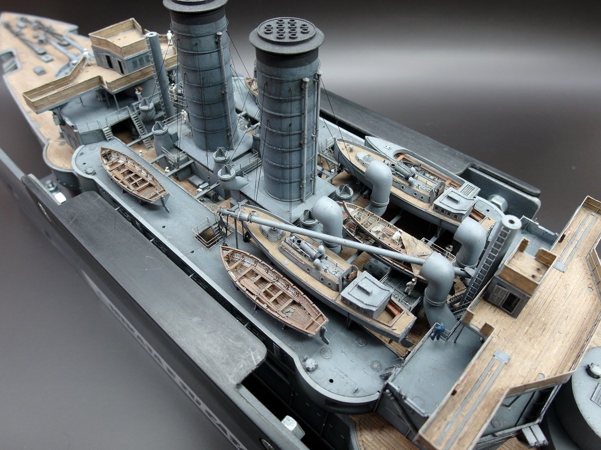
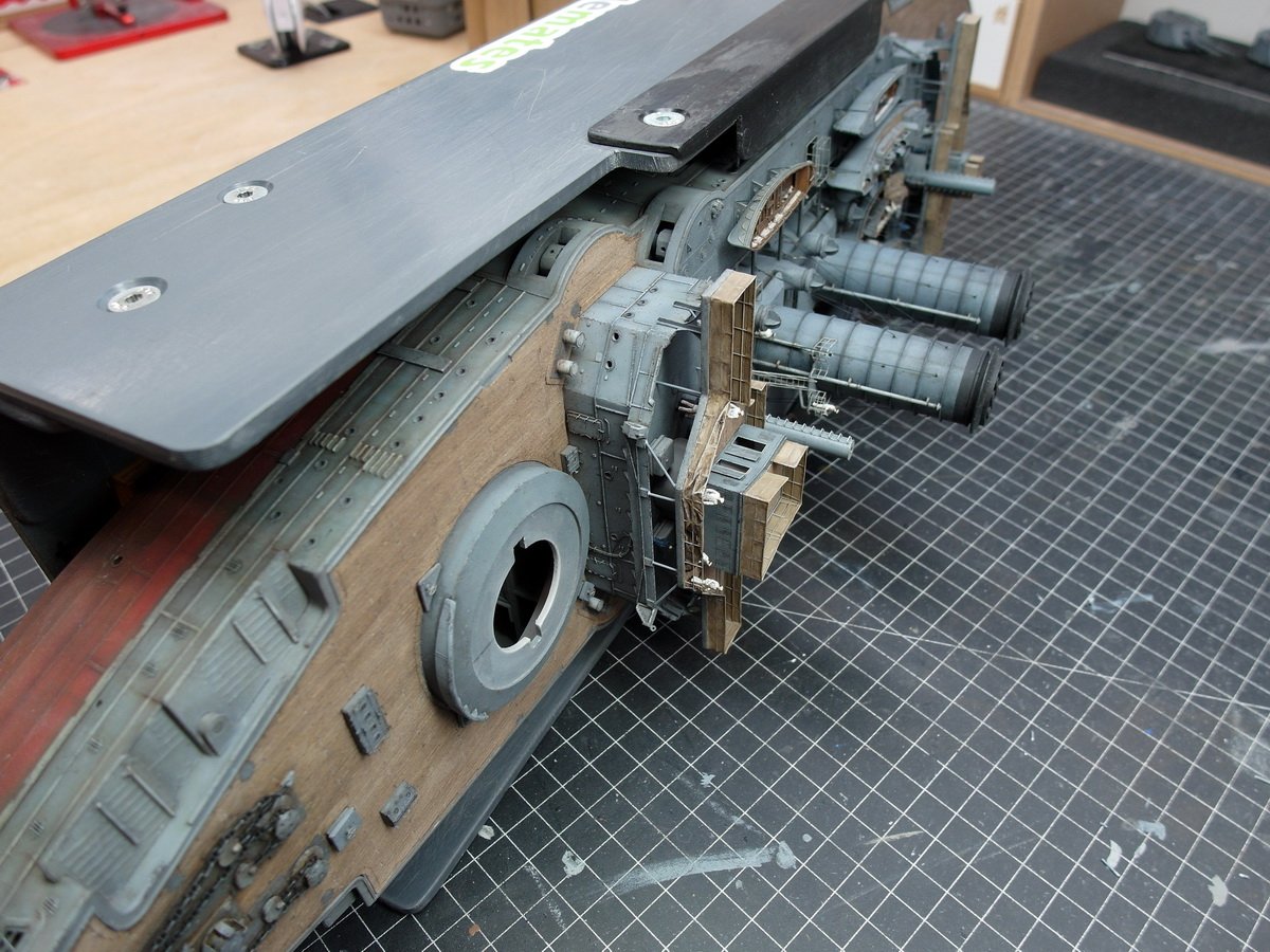
Many thanks, Roel. 😊 Next, I tackled the crane boom and the wind vents. I’m actually installing the crane boom very early on, for two reasons. First, this allows me to finish the work on the amidships deck, and second, I want to put the upper part of the masts in place as late as possible. On the Mikasa, they are much taller and more delicate than on the Bismarck, making the model quite unwieldy. And so I got started. First, I created a mounting for the pulley on the boat deck. This consisted of two deck eyes and a base plate. The nice thing about this was that it gave me a little more leeway when aligning the crane boom. The hook could be moved up and down a bit in the bracket, which simplified things. Then I assembled the missing wind vents. And without further ado, let’s get all that stuff onto the model. The crane boom is placed on a support. And the pulley system can be conveniently parked on the deck. It’s a damn tight fit, but it works.
- 212 replies
-
- 6
-
-
-
- Russo-Japanese War
- Mikasa
- (and 2 more)
-
That's true. It's easier for me at 1:200. And I wasn't sure at first if it would look good either. I only knew I liked it once the paint was on. Take a look at post 20, you can see the result there.
- 23 replies
-
- 2
-
-
- Viribus Unitis
- Trumpeter
- (and 1 more)
-
I do think it's visible through the surface coating. I had initially planned to do the same with my Mikasa, but then I solved it using styrene profiles.
- 23 replies
-
- 1
-
-
- Viribus Unitis
- Trumpeter
- (and 1 more)
-
Today I completed a small but exquisite detail, exactly as written. But let’s start from the beginning. The forward bridge building was still missing some colored lights—the navigation lights. Port… And starboard… Now I could finally get to work on my shelves. First, I cut a lot of profiles to size. Painstakingly glued together and painted brown. I folded long strips of tissue paper using an accordion-like technique, colored the ends, and then cut them off. That’s how each letter was created. Here you can see A to E. I couldn’t get more than five in a row, so in the end there are only 20 letters on the shelf. Please forgive me. 🥲 Then I set it up on the object of my desire to test it out and let it work. I really like it. And I also made the attachment points for the ropes flatter. They were still too high for me. Successful Sunday. 👍


- 212 replies
-
- 7
-
-
- Russo-Japanese War
- Mikasa
- (and 2 more)
-
A beautiful ship. What you're building looks absolutely fantastic; I'd love to come aboard.
- 23 replies
-
- 2
-
-
- Viribus Unitis
- Trumpeter
- (and 1 more)
-
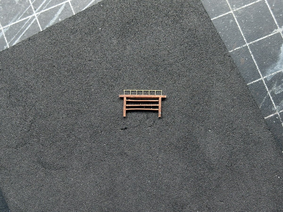
I've finished the bridge and its girder and am now starting to add more details. First, I'll take care of the signal flags. So I created this prototype. For this, I've built a small wooden cabinet out of styrene to store the flags, which I'll probably make from tissue paper. I'm toying with the idea of having a figure here later, holding one of the signal lines to raise a flag, something like this... Now I have to build four of these little cabinets first, I'll keep you posted.
- 212 replies
-
- 6
-
-
- Russo-Japanese War
- Mikasa
- (and 2 more)
-
@Jeff59 Thank you. And once again, thank you for this valuable information, Jeff. You are a wellspring of knowledge. 👏
- 212 replies
-
- 2
-
-
- Russo-Japanese War
- Mikasa
- (and 2 more)
-
Hi Terry. It's very unfortunate that Amati is letting its customers down with such errors. It just goes to show that companies don't think it's necessary to do a little research before launching a product. Especially since the effort required to gather this information is extremely small. Despite everything, you're making a great model out of it. 👍
-
Hi Terry, a beautiful and interesting build.👍 However, there's one thing that's not quite right. DKM submarines don't have a red underwater hull. The hull color corresponds to today's RAL 7016, or anthracite gray. I don't know how historically accurate you want your model to be, but I thought I'd point it out. 😉
-
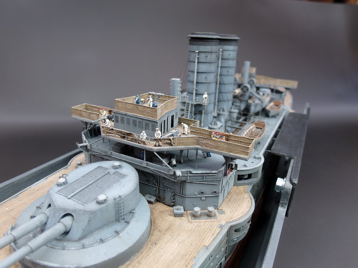
Happy New Year, everyone! Let’s get our glue out again in 2026 and, above all, stay healthy so we can continue our wonderful hobby. I used my day off to tackle another tricky task.You might remember that I wanted to do things differently than planned when mounting the posts that support the bridge on the bridge deck. First, I glued the bridge securely in place yesterday and let it dry thoroughly until this morning.Then I pushed the posts through the holes I had already prepared. The profiles at the top were cut to size, and that was it. A little brown paint, and you can’t see them anymore. Then I attached the support pillars at the front. That was a bit tricky, to be honest, but it worked. Thanks in part to my assembly stand, which allowed me to lay the model on its side again and made the job much easier. And so the bridge and its supports are now in place. It wasn’t easy to align all the support pillars perfectly straight and parallel to each other. I really like working with the team below me. The posts still need to be aged, but I'll do that this weekend.
- 212 replies
-
- 8
-
-
- Russo-Japanese War
- Mikasa
- (and 2 more)
-
Thank you so much for the lovely compliment, Chris. Yes, I plan to take the model to one or two trade fairs. First, the largest plastic model building fair here in Germany, the Euro Model Expo. And then there's one in the Netherlands, the Scale Model Challenge. And every now and then, friends of mine put on a temporary exhibition at the Maritime Museum in Hamburg. I'm also considering taking the Mikasa there. I'm already working on a transport box so it survives the journey undamaged.
- 212 replies
-
- 5
-
-
- Russo-Japanese War
- Mikasa
- (and 2 more)
-
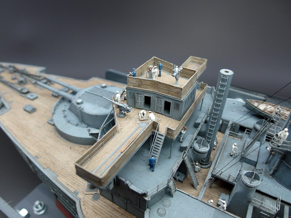
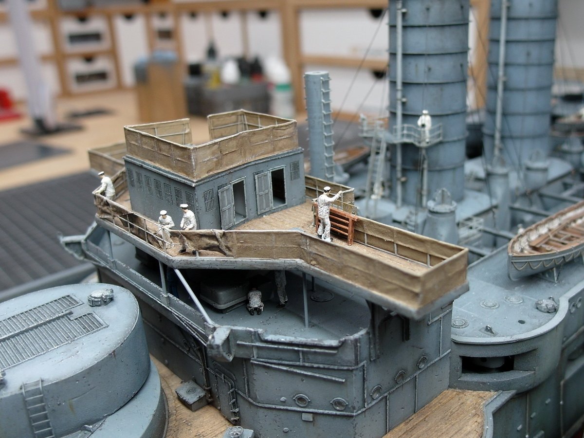
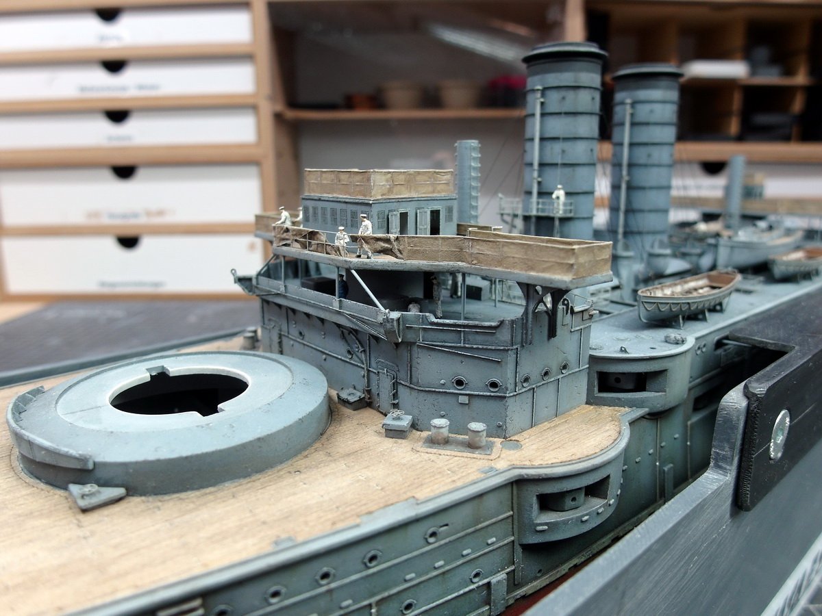
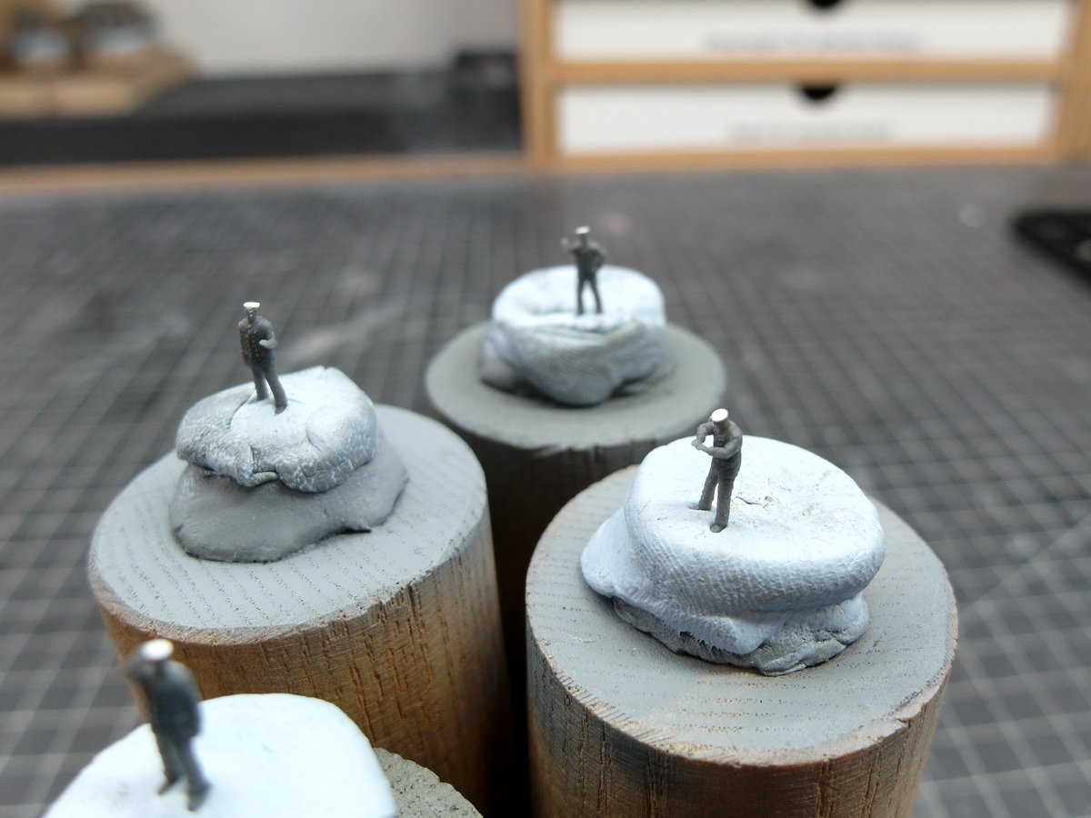
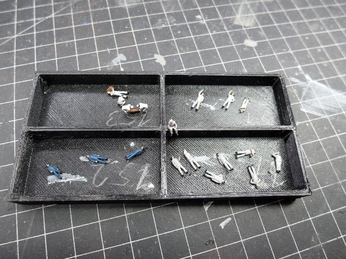
Hello everyone. I used my time off to recruit even more crew. They’re actually members of the German Navy. But as soon as they received a nice new styrene flat cap, they started speaking Japanese. 😁 So I’m further increasing the number of available figures. Everyone dressed up and ready to board the ship. I remembered the words of user dafi from a German forum, who spoke of group formation, and I hope I’ve implemented it adequately. With a group of sailors talking amongst themselves. What could the boys possibly be chatting about as soon as the officer turned his back on them?! Something needs to be repaired on the fan cover, and a sailor is bringing more equipment to the storage lockers. An officer steps out of the armored command post and the sailor gives a brisk salute. At the stern, a sailor goes into the control station, and an officer keeps an eye on the boys working in the pinnace. I’ve already distributed the figures on the lower deckhouse, so now the upper bridge with the cams can finally be installed. I would have difficulty reaching those spots afterwards, so that’s how I did it before. Even these figures are barely visible afterwards, but again they give the model depth and a touch of life. The good thing is that I could easily use the DKM sailors with their incorrect clothing.
- 212 replies
-
- 7
-
-
-
- Russo-Japanese War
- Mikasa
- (and 2 more)
-
You're very welcome, Ferrus. And it seems you've hit the mark. Your tarp turned out great. And on your first try, impressive! 👍
- 17 replies
-
- 1
-

-
- barco rabelo
- 1/75
- (and 2 more)
-
@Ferrus Manus Thank you so much. I use tissue paper that I dye brown. Then I soak it in diluted wood glue and shape it. For example, I lay it over a boat and lift the paper with tweezers, folding it over itself to create an arrangement of folds. Then I let it dry thoroughly. After that, I apply a wash with very diluted dark brown paint. I let it dry again and then drybrush it with a light brown or light gray. I hope you find this helpful.
- 212 replies
-
- 4
-
-
-
- Russo-Japanese War
- Mikasa
- (and 2 more)
-
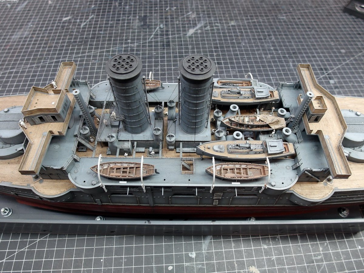
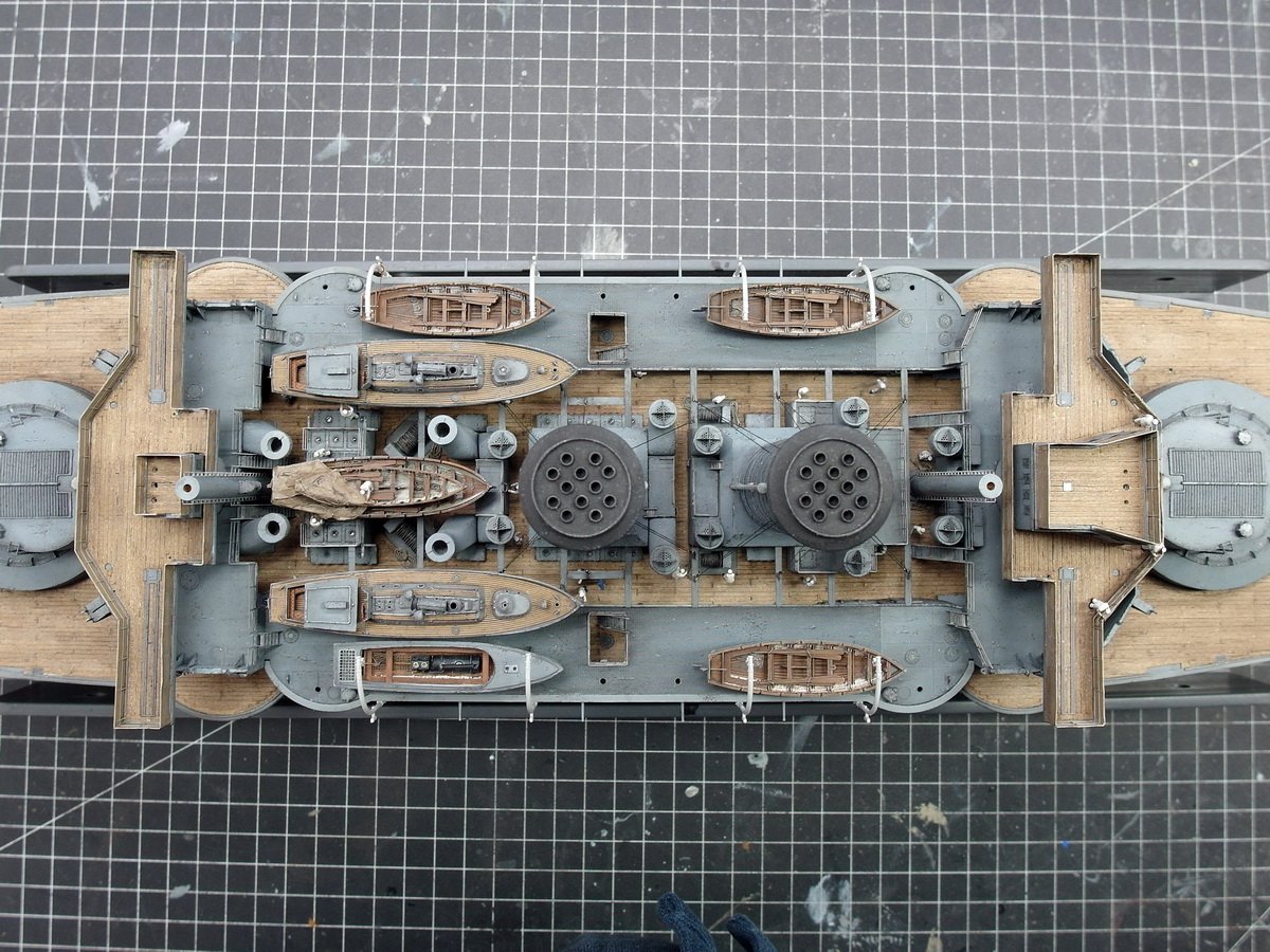
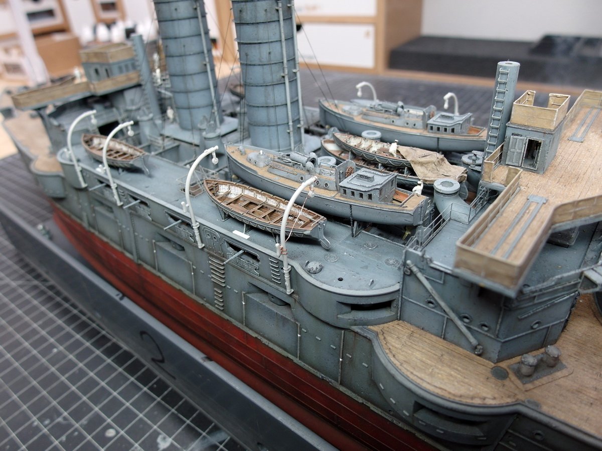
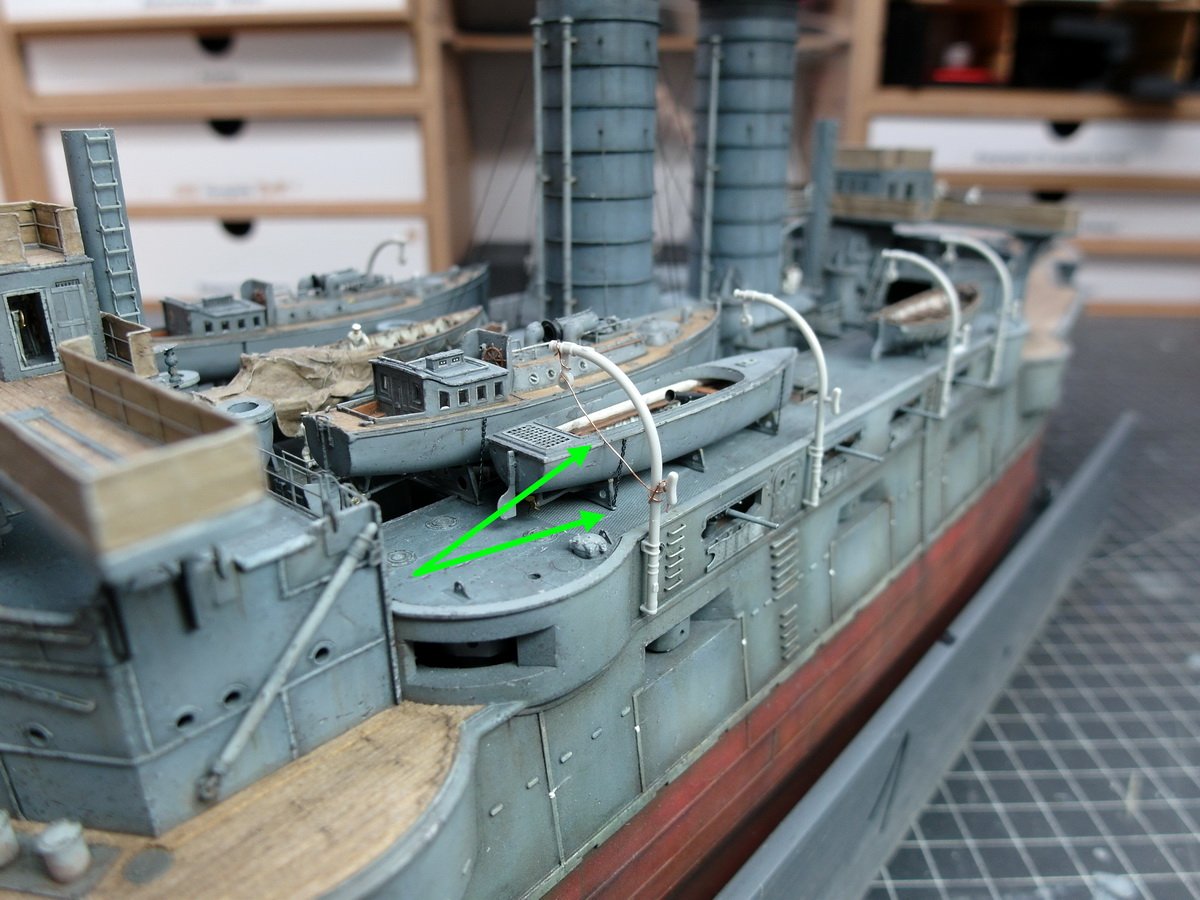
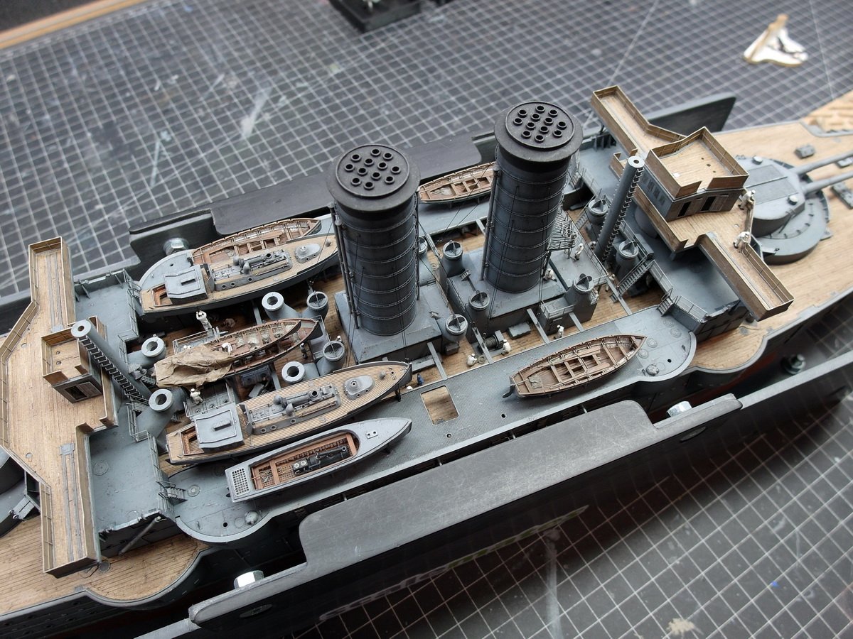
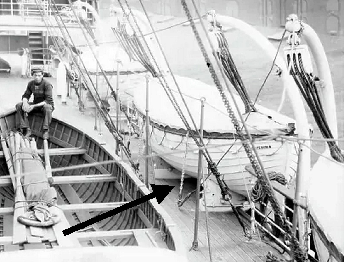
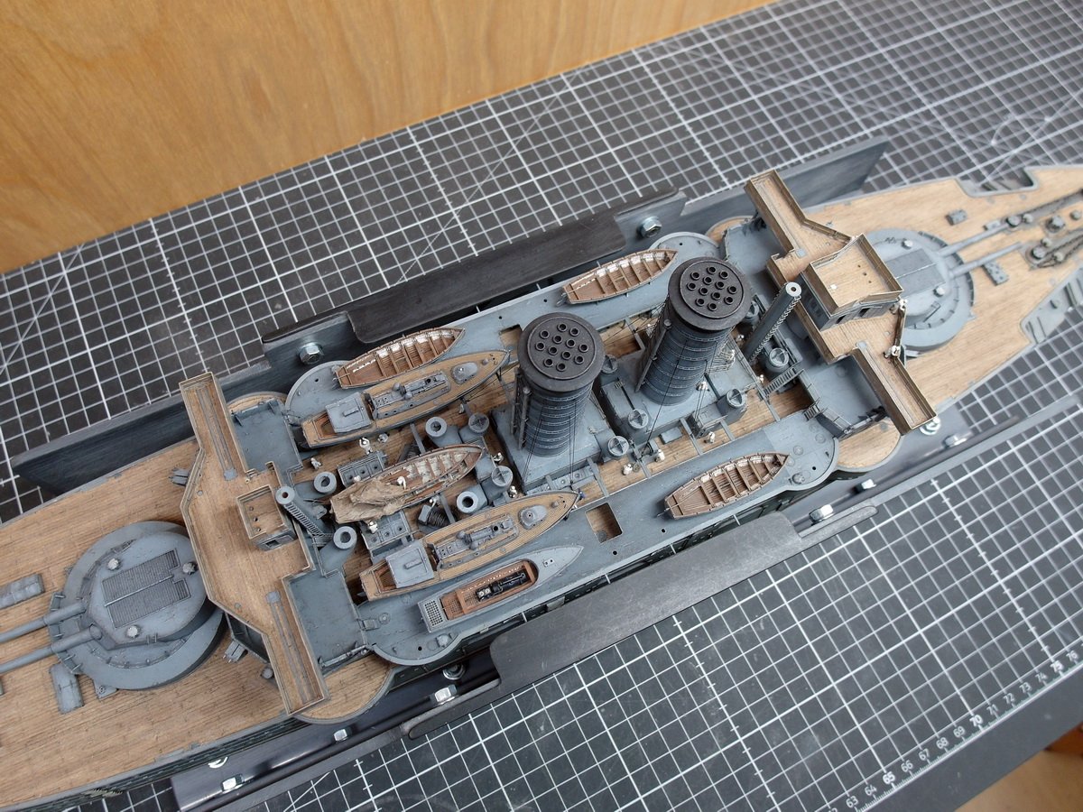
I’ve slightly opened up my assembly jig again to determine the positions of the launch and cutter. To do this, I removed the davits from their injection-molded frames and inserted them into the designated holes. Then, using a small strip of styrene profile, I positioned the boats at the same distance from the outer edge of the hull. So far, it’s looking pretty good. It’s definitely a tight fit, but I can get all the little boats in place. Before I secure them, though, I’ll make sure everything is perfectly aligned. I simulated the rope of the pulley system with a wire, and it fit quite well on the cutters. However, this doesn’t work with the barge. The arrow shows where the rope hits the stop and the barge has shifted backward. Here I need to raise the davits or modify the pulley system. And so the ship continues to take shape.
- 212 replies
-
- 7
-
-
-
- Russo-Japanese War
- Mikasa
- (and 2 more)
-
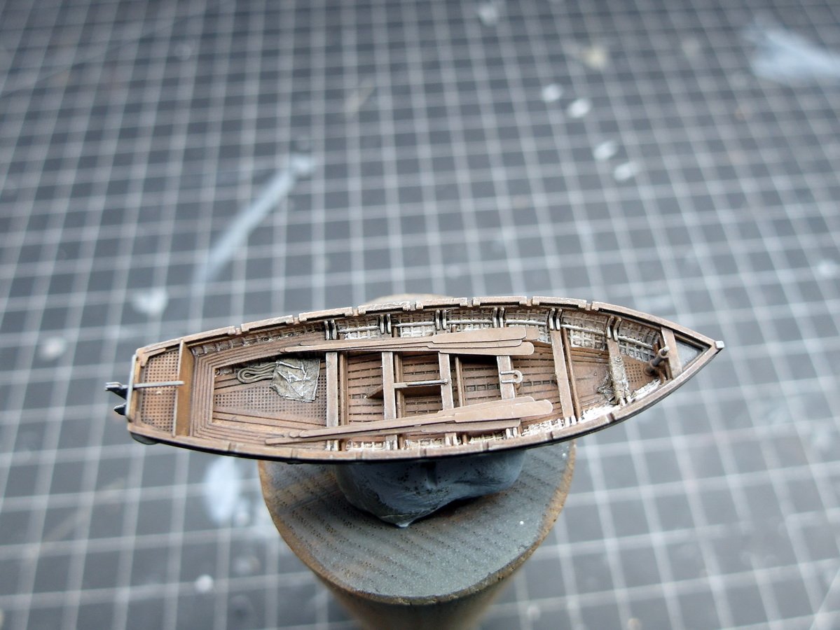
I have a small addendum regarding the cutters. It didn't seem right to me to leave the oars unsecured in the boat. So I secured them with a rope to prevent them from slipping. And this is what it looks like now on the Mikasa. And with that, I wish you all a wonderful and peaceful Christmas. 🎅
- 212 replies
-
- 8
-
-
- Russo-Japanese War
- Mikasa
- (and 2 more)
-
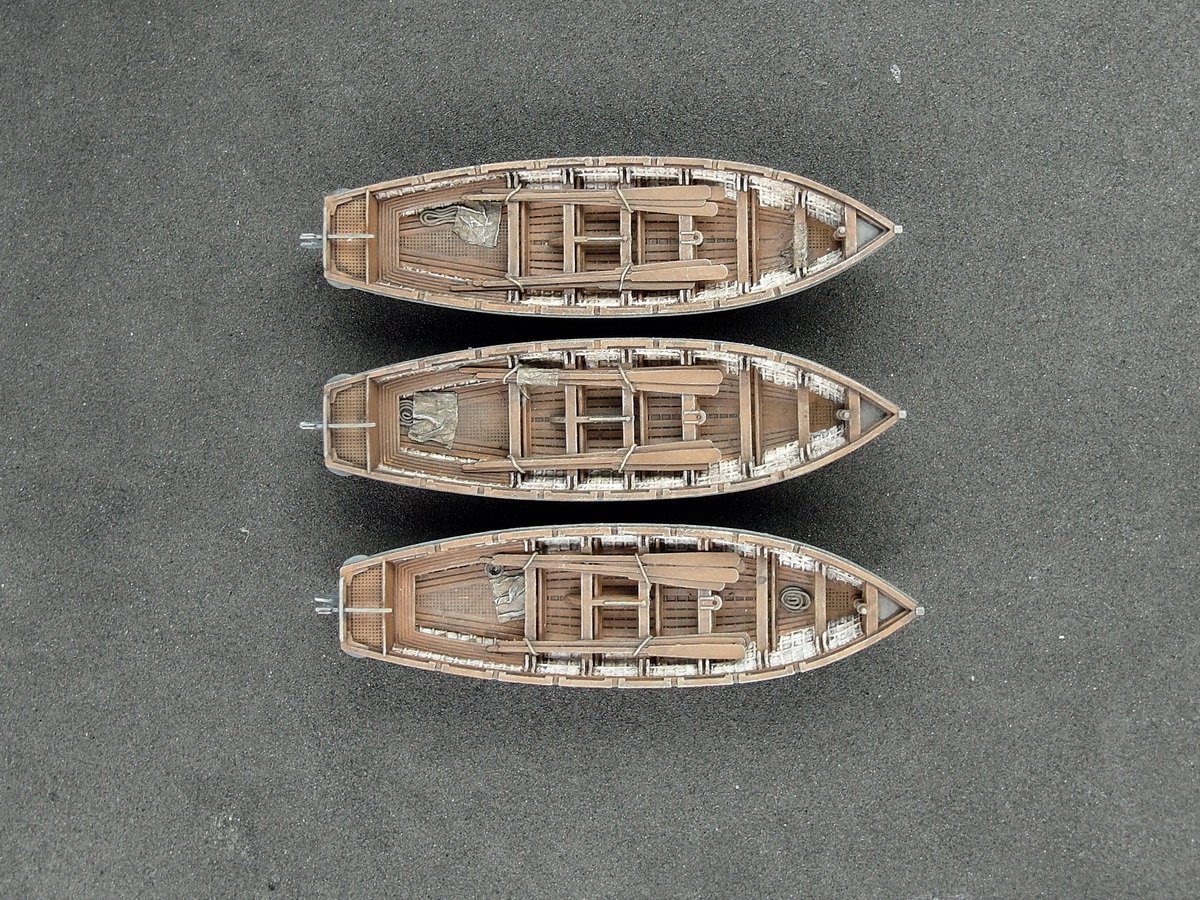
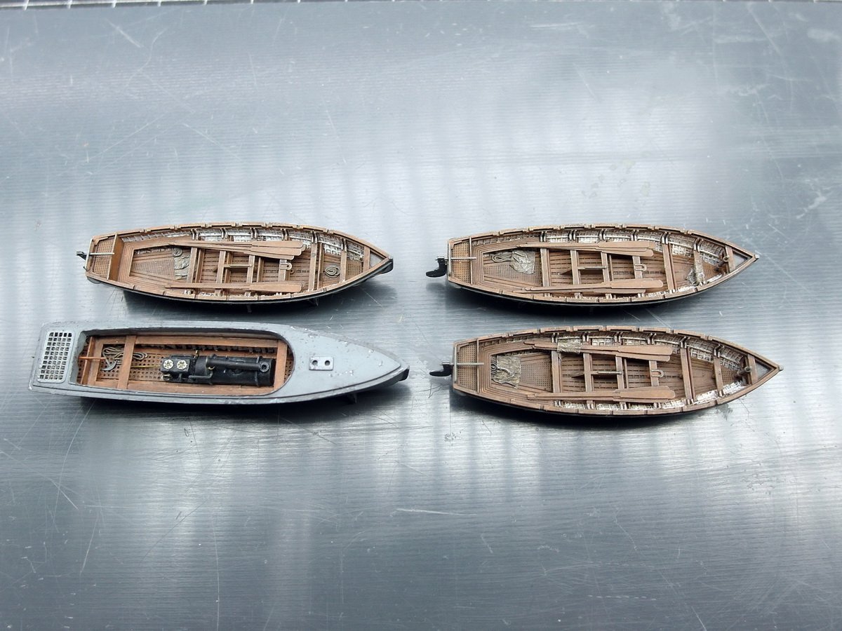
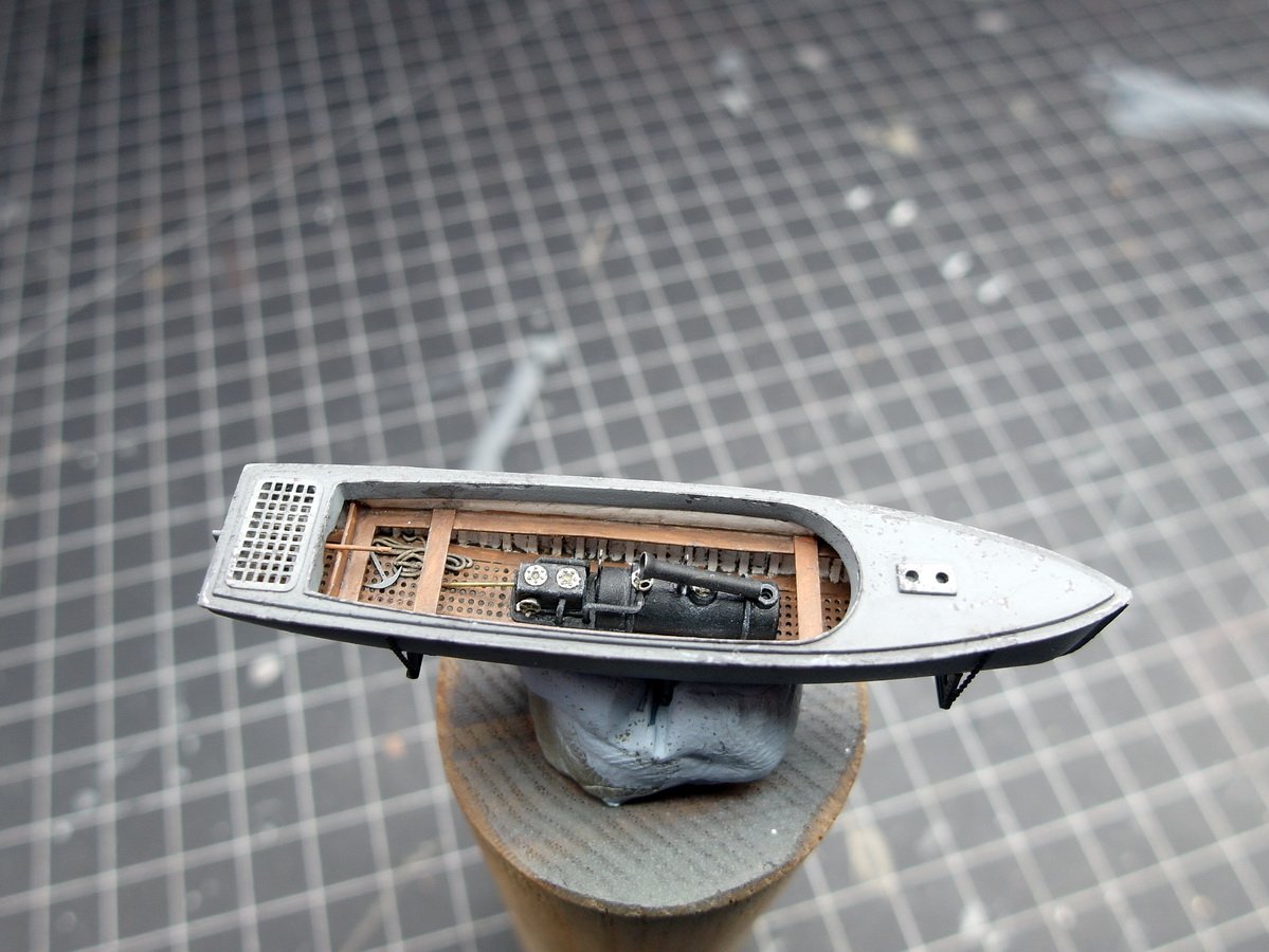
Oh man, how true. 😅 Not much has happened since the last post. But I finally managed to finish the top row of cutters and the steam launch. The oars have been distributed among the cutters. Here are the details again. I’ve distributed some more ropes. And I packed a little bit of tarpaulin into the boats. That’s how I tried to make them a little more varied. The barge has also been given a small anchor. At first, I wasn’t quite sure how to secure the cutters. But then I found a picture showing that even the small boats were secured with a chain hoist. And that’s how I implemented it. And I wish everyone here a Merry Christmas. 🎅

- 212 replies
-
- 12
-
-
-
- Russo-Japanese War
- Mikasa
- (and 2 more)
-
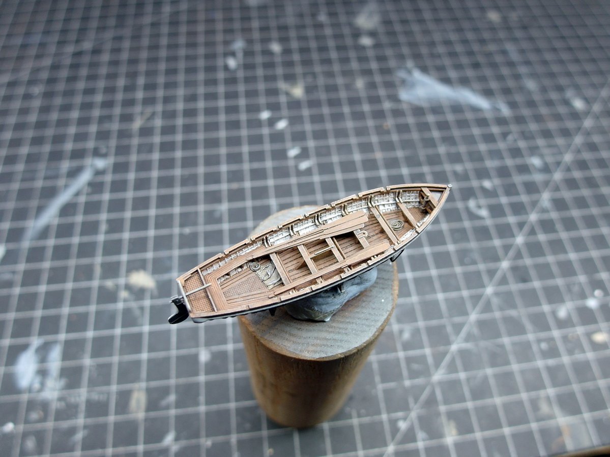
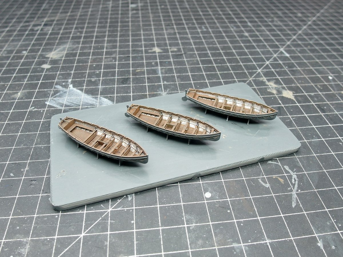
Thank you so much, Jeff, and Merry Christmas to you too! That's right, I've finally finished the little cutters and I'll show them to you in a moment. I'm really looking forward to seeing your display case when you present it here. And I can only return the thanks for the tips and support, Jeff. Here's to a happy new year with lots of glue! And now to the boats. Aged… …and positioned for testing. I definitely like it better than with the white floorboards.
- 212 replies
-
- 8
-
-
-
- Russo-Japanese War
- Mikasa
- (and 2 more)
-
The little mast is absolutely fantastic. What a tiny gem! 🫠 I also have that small vise, by the way, and I think it's great too.
- 40 replies
-
- 3
-
-
-
- Five Star
- Akitsu Maru
- (and 1 more)
-
Thank you for the interesting video of the museum ship, Andy. 👍
- 212 replies
-
- 2
-
-
- Russo-Japanese War
- Mikasa
- (and 2 more)
-
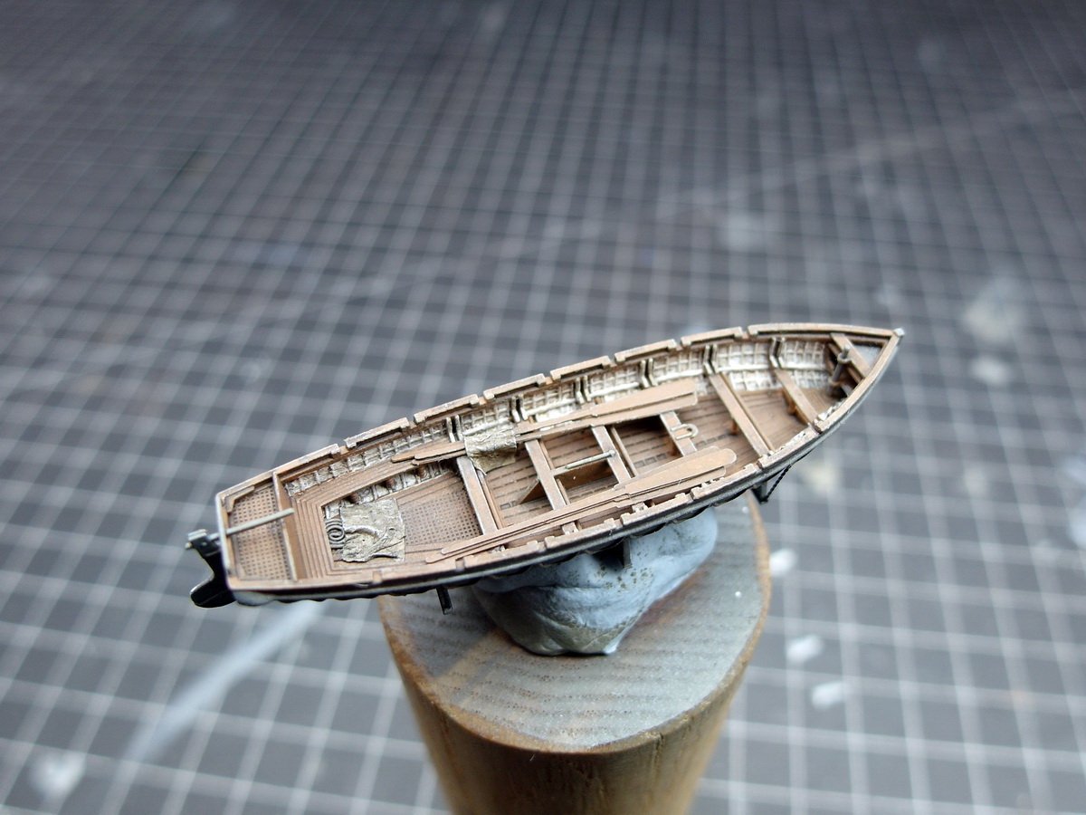
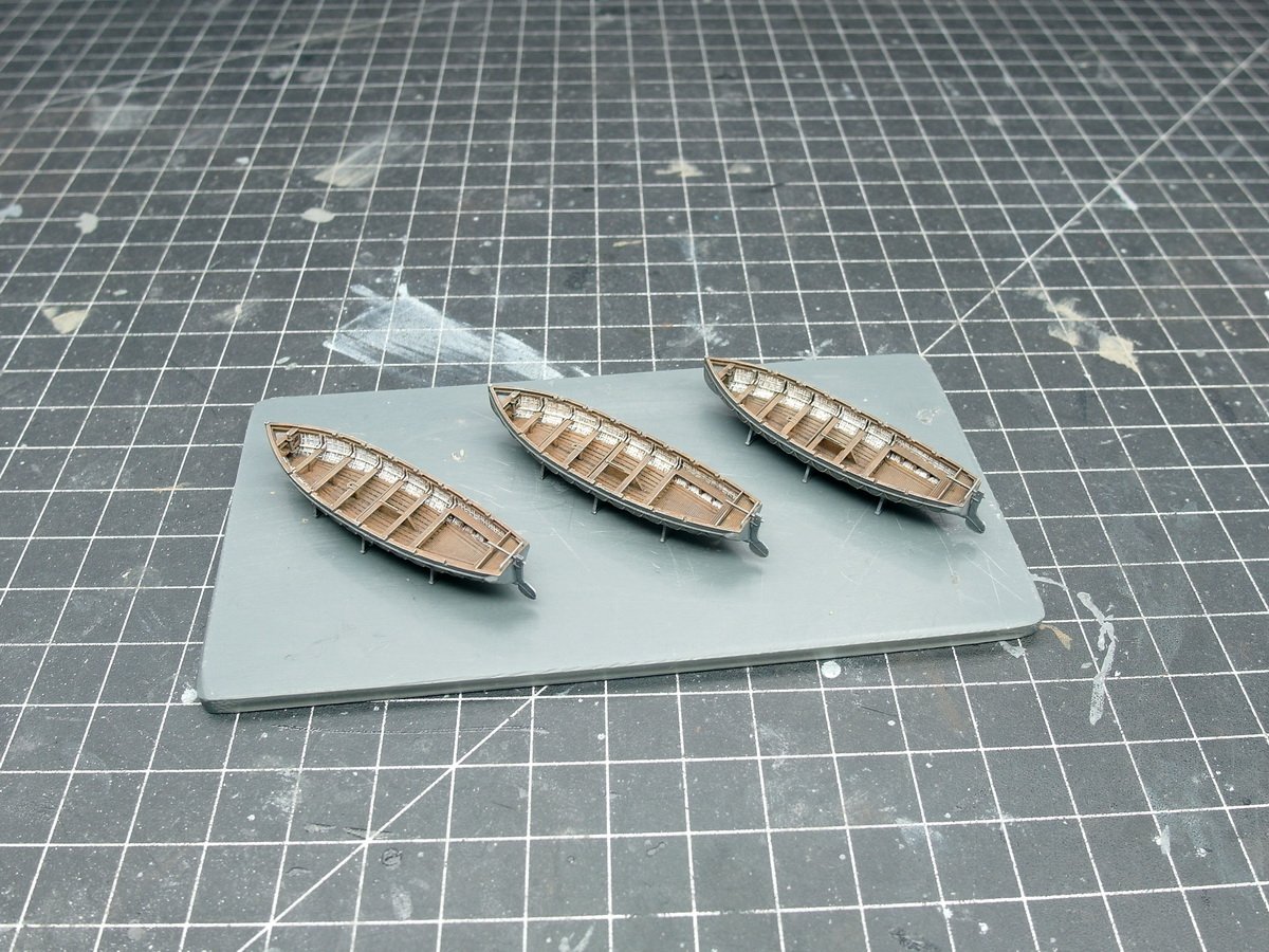
That's so kind of you both, thank you so much. Have you ever heard of this?! Nothing is as constant as change. I was thinking about the 32-foot cutter and its color scheme again this week and simply changed it. It didn’t seem right to me that the tidy Japanese would soil the white floorboards with their feet. I believe it’s generally accepted that the inside of the hull was painted white. But the floor would get dirty very quickly. So I redid it and painted the floor in wood tones. I think it looks much better now. And placed on the deck. Yes, better.


- 212 replies
-
- 8
-
-
-
- Russo-Japanese War
- Mikasa
- (and 2 more)
-
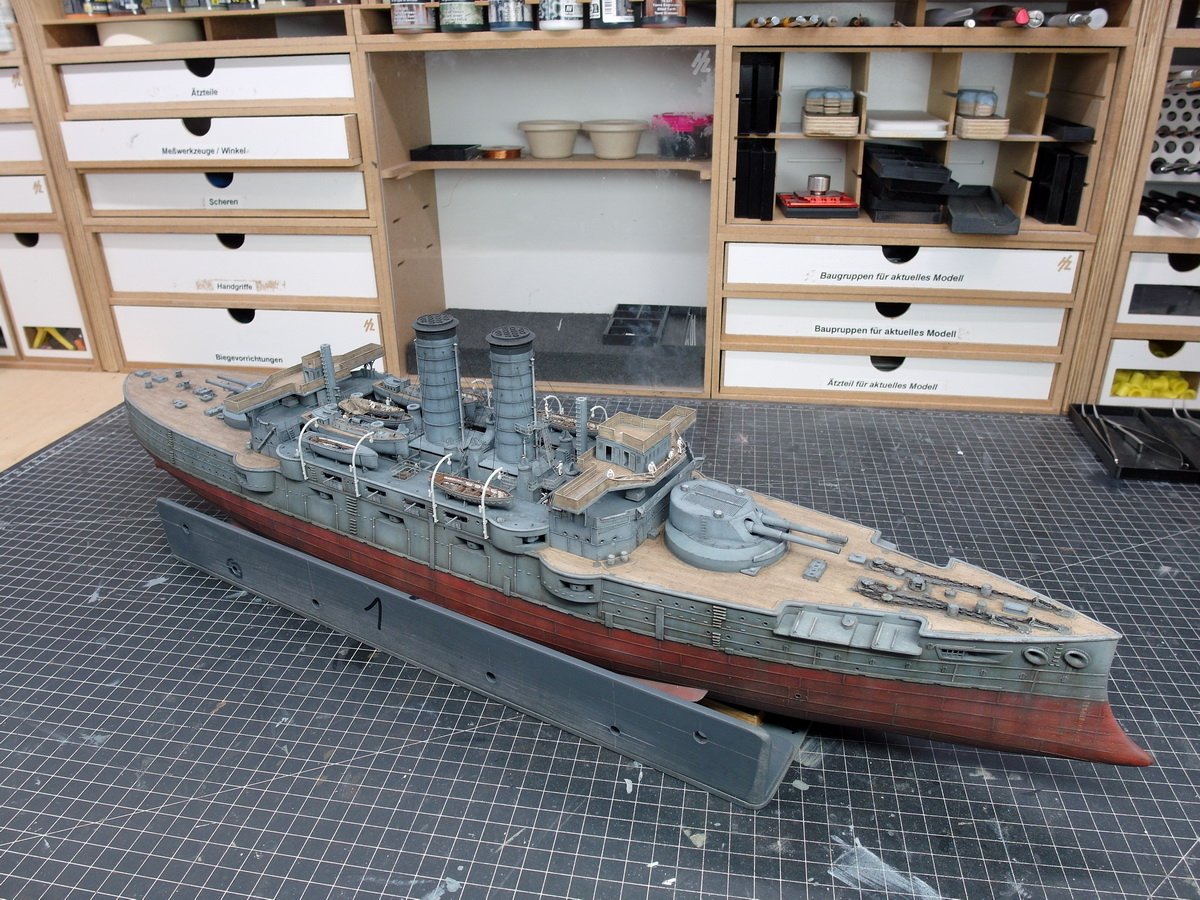
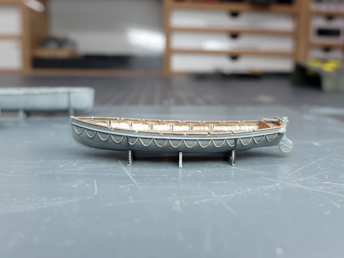
Hello everyone and happy first Advent. I've finally finished installing the tarpaulins on the bridge, completing another delicate task. And here's how it looks now. After consulting with users, the supports on the railing for the sunshade were removed and will be folded up and stored on the deck later. This was likely related to the work being done on the tarpaulin. Since the bridge is roughly finished, I wanted to continue working amidships before attaching it to the Mikasa. So I turned my attention to the three missing lifeboats. And subject them to the usual procedure of painting details and weathering. The first cutter is finished. Micro Master makes truly first-class 3D prints. Painting the rope neatly on the side of the cutter was truly a test of patience. But the middle deck is also slowly filling up. Starboard deck complete.


- 212 replies
-
- 8
-
-
-
- Russo-Japanese War
- Mikasa
- (and 2 more)