


Decoyman
-
Posts
97 -
Joined
-
Last visited
Content Type
Profiles
Forums
Gallery
Events
Posts posted by Decoyman
-
-
I'm considering that. The problem is keeping the cling-film in place and flat.
In actuality (as far as I can see having not tried yet) the main area where glue might get onto the mould is the overlap between floor and futtock. Perhaps a strip of cling-film just there might do. On the other hand it might get in the way.
Because I'm not gluing the floors to the keelson yet the frames should be loose until the planking goes on; that ought to let me loosen them if they get stuck temporarily. On balance lots of opportunities to avoid mishaps, at least in part thanks to Jeronimo's pathfinding!
Rob
-
That's what I'm afraid of!!
-
Thanks Michael.
It probably looks worse than it was. As you say, it's an interesting way of building, particularly at such a large scale. It would be useful if I was mass-producing chaloupes, but for a one-off, it's quite a lot of work which is ultimately redundant. The acid test will be once the planking is finished and I have to try to remove the boat from the mould. I'll admit I'm feeling a certain amount of trepidation at the moment.
Rob
-
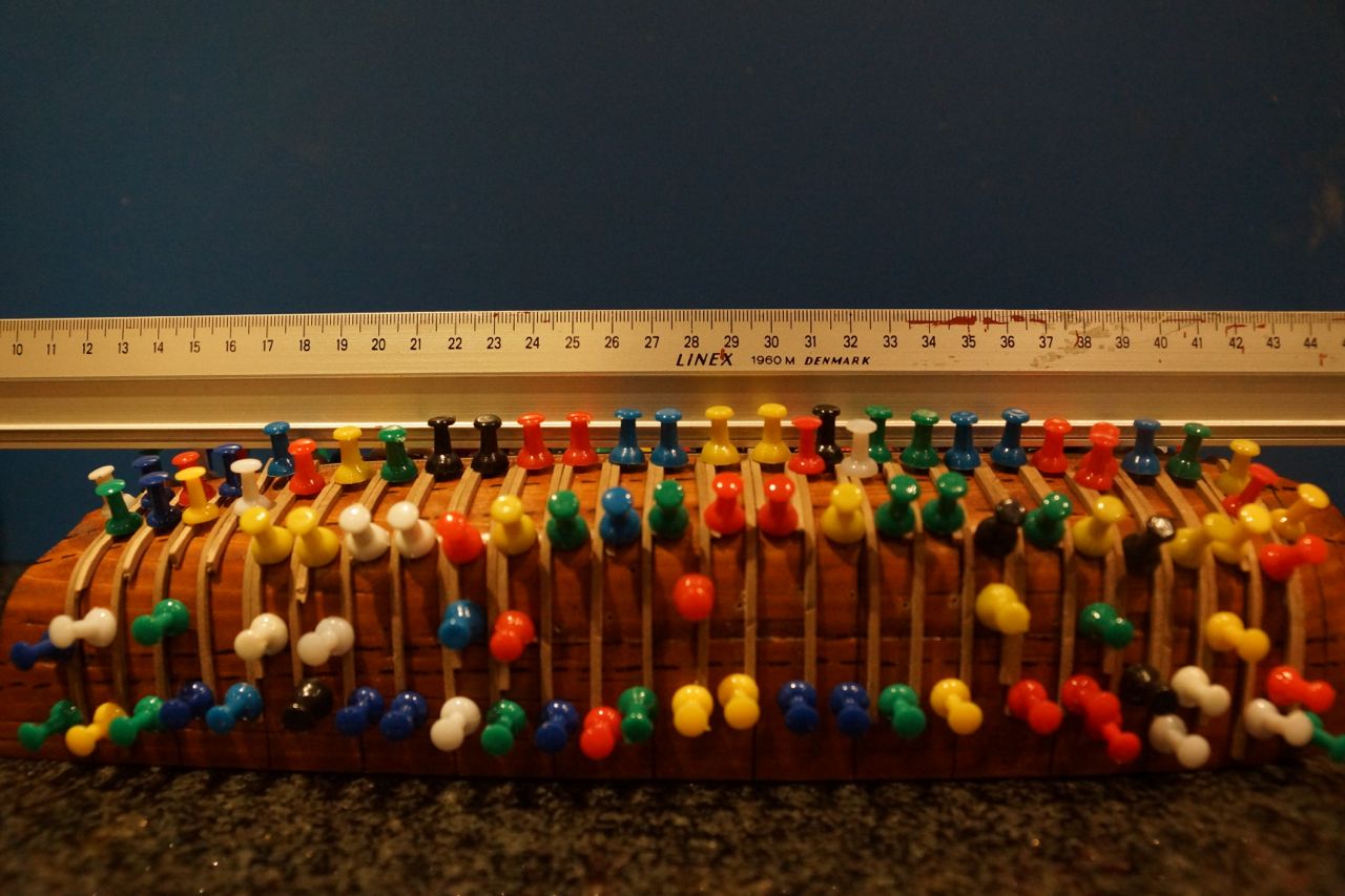
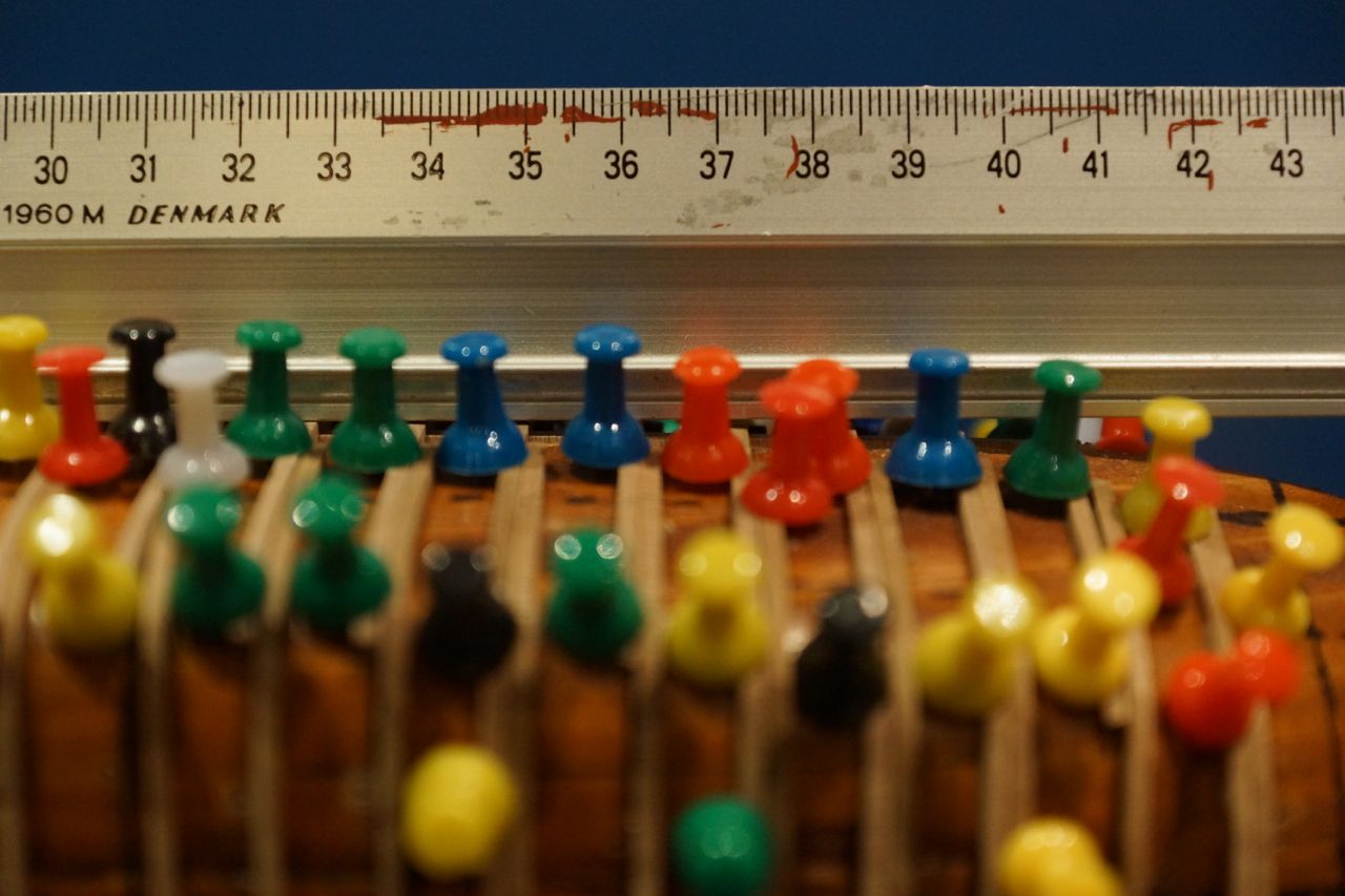
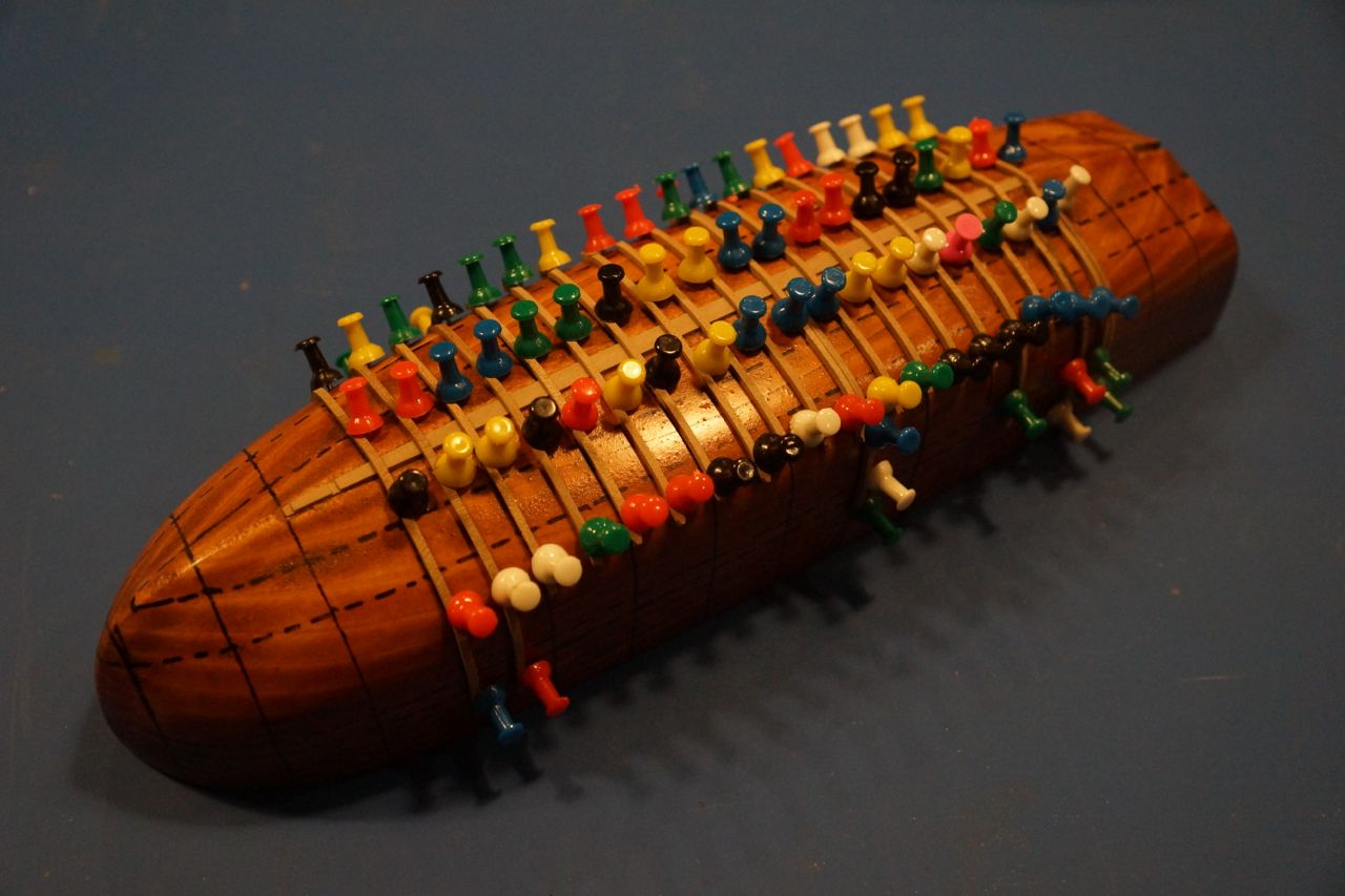
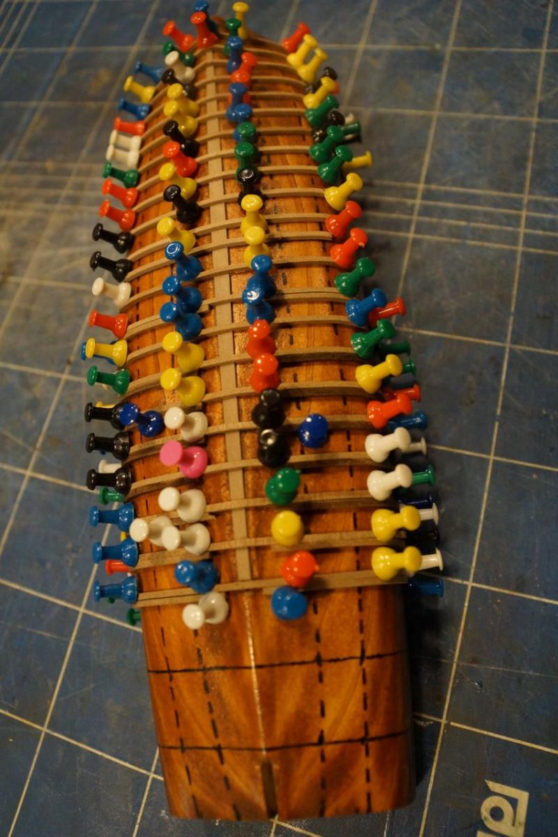
I am getting close to finishing the initial fabrication of the frames. In the next couple of pictures you can see all the frames across the keelson finished and then the futtocks added to the rearmost crutches.


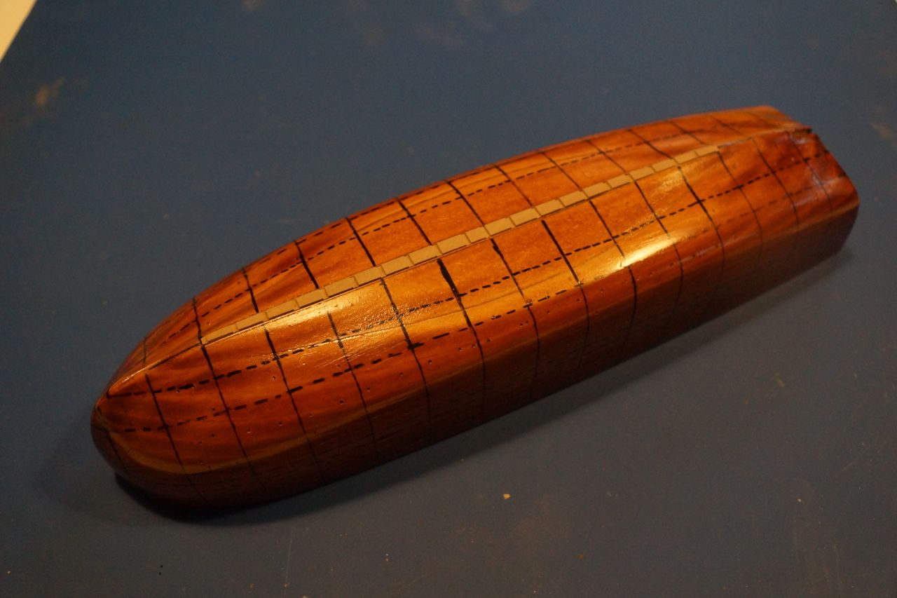
Unfortunately I noticed that the keelson had acquired a pronounced downward curve (upward in the photos since the mould is inverted).


I wasn't happy to leave it like it was, so I stripped off all the frames - they were only pinned in place - and then planed off the first MDF layer from the mould down to the veneer leaf.
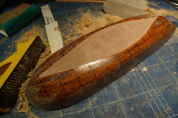
At this point it became clear that the whole mould was slightly curved, probably because I didn't clamp it to a flat surface when it was drying. Nothing serious, just slightly annoying! I was able to sand the veneer slightly more in the middle until the top surface was flat. Then I added a strip of cherry the same plan profile as the keelson, as thick as the distance between the top of the keelson and the lowest waterline and with a curve at the stern end. Once this was glued down I fixed 4 mm deep strips of veneer each side to set clean lines for the bottom of the mould (the MDF tends to flake off). Now I have a straight base for the keelson.

Next I cut a new layer of MDF in two pieces to fit around the keelson trough and, once the glue was dry, planed and sanded it to shape. Another couple of coats of varnish to stop the frame glue sticking and job done! A nice straight keelson ready for the frames to be re-fitted.

Rob
- Elia, Mirabell61, fatih79 and 3 others
-
 6
6
-
-
Jeronimo,
I saw your log and the photos of the finished boat - fantastic work. I hope mine is somewhere near as good (although I have my doubts… we'll see).
Aykutansin,
Thanks for the encouragement - do you have a build log of your own?
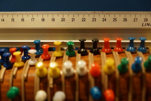
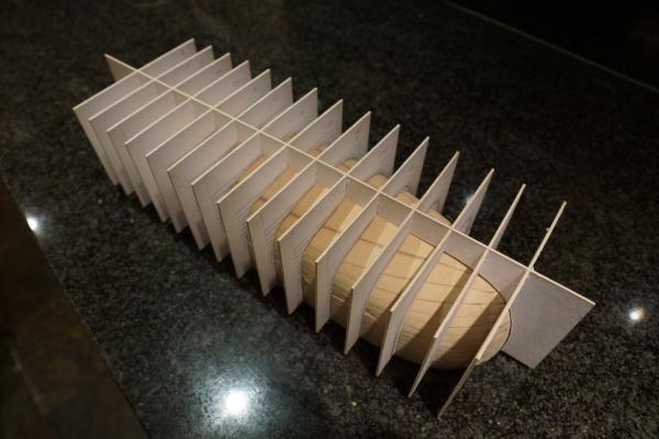
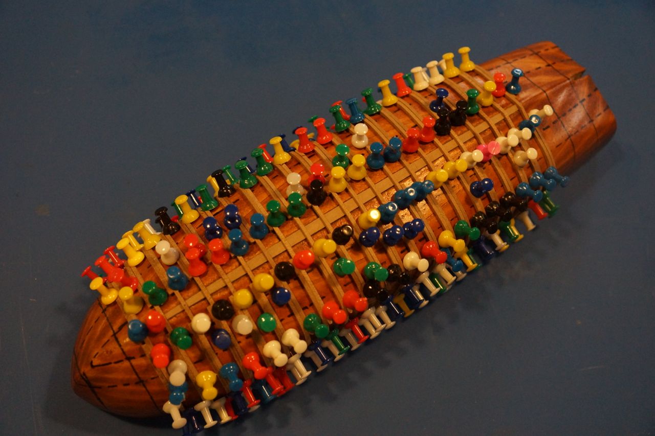
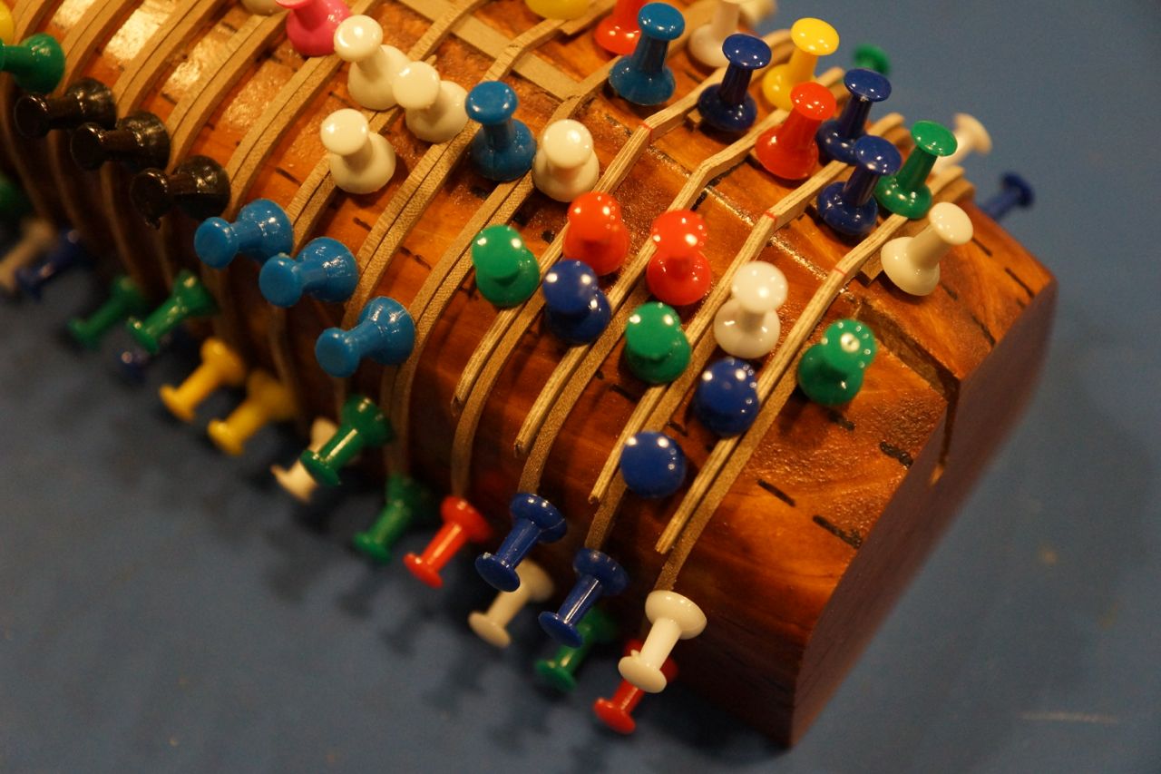
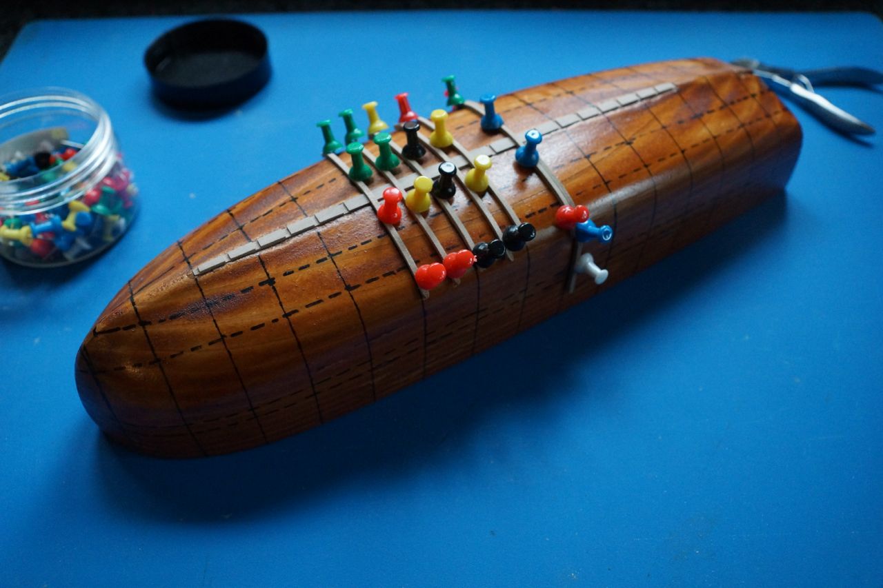
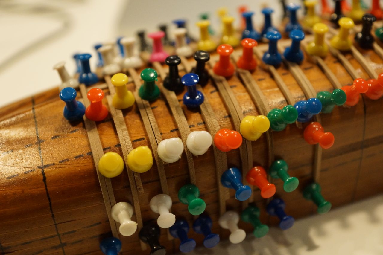
Here are some more photos of progress to date. I've set the keelson in its recess in the mould and started adding the frames. The instructions suggest pinning through the frames. I decided to use push-pins. A big benefit is that they can be removed more easily once the frames are finished (you don't want to miss a pin after adding the planking - removing the shell from the mould would be a bit difficult…). Another advantage is that lifting a pin slightly allows the frame to be adjusted laterally until its position is perfect.
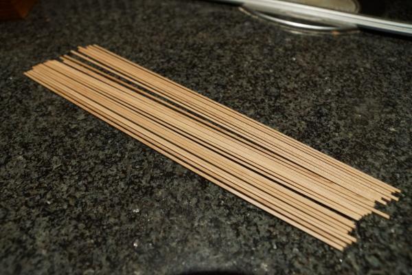

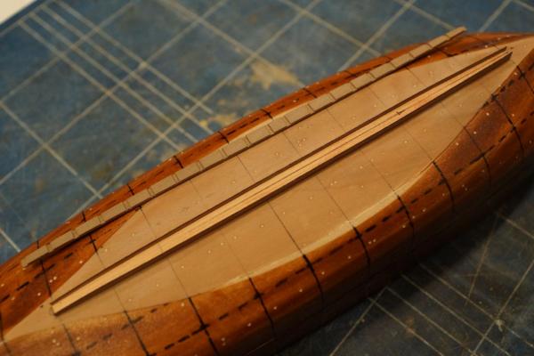
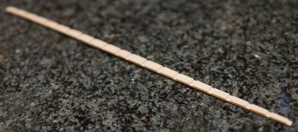
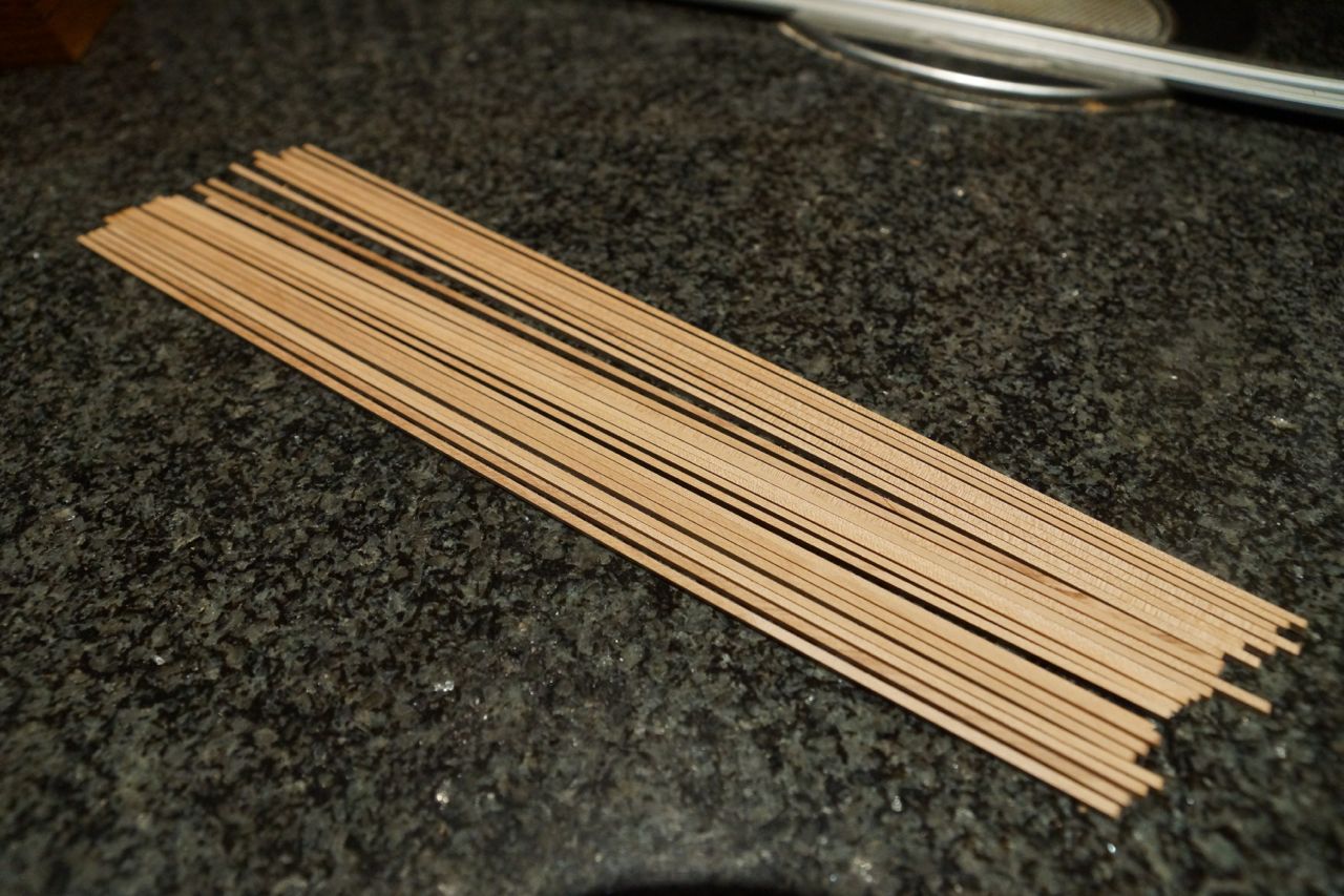
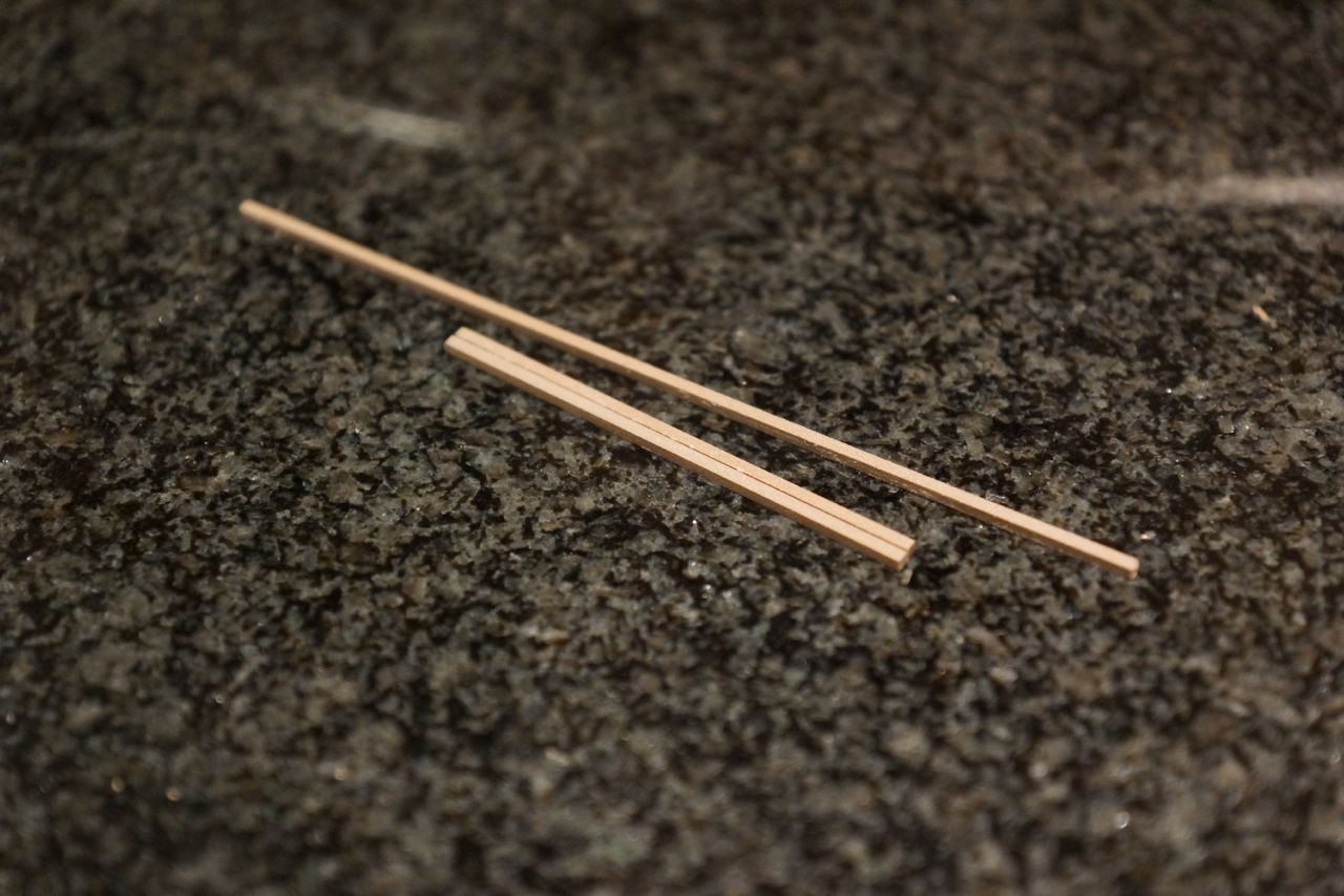
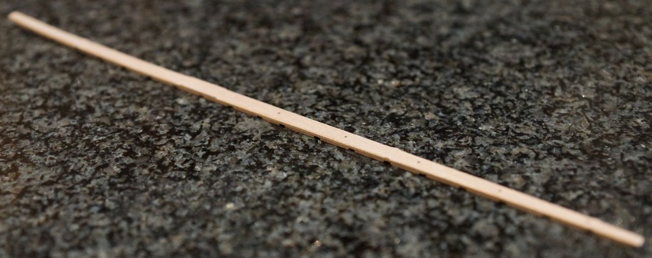
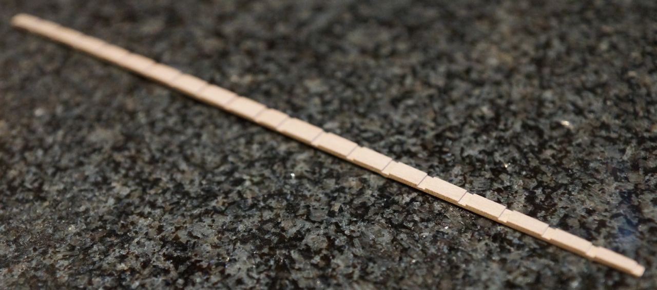
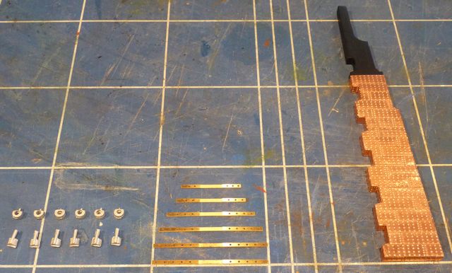
I'm using apple for the frames as well as the keelson. Slicing it up into 2 x 2 mm pieces results in incredibly smooth faces straight from the saw. I give them a rub-down with 400 grit wet and dry used dry then soak them overnight. The first picture above shows all the pieces cut up: there are 30 of them, corresponding to 30 frames, each strip is 300 mm long. The second picture shows a set of timbers for a typical frame - a long piece for the floor and two shorter pieces for the futtocks.
The following pictures show steps in adding the frames to the mould with the keelson in place. Interestingly nothing is glued yet. The keelson is intended to remain loose until the hull is removed from the mould, at which time it will be pinned and glued in place. Initially I soaked the wood in hot water, but I found I broke quite a few pieces trying to bend them round the sharp curve between the floor and the sides, so I added some household ammonia to the water. I am now having more success, but this may be because a] I'm getting better at forming the bends or b] I've left the wood to soak for longer or c] I tried microwaving the container with the ammonia solution before taking the wood out. Anyway it seems to be going OK!

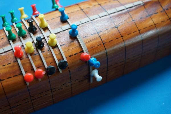


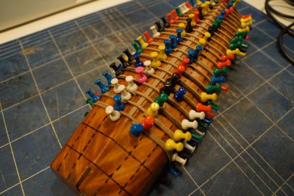
In the first three images the floors are being added; in the last three I am starting to add the futtocks. The darker pieces have been added later and are still wet.
Rob
- yvesvidal, gjdale, Wishmaster and 9 others
-
12
-
Thank you all for your kind words.
Slog: comparing my work with Gil's is praise indeed and I'm not sure I deserve it! I'll take some detail pictures at the weekend at post them in the completed builds gallery. I might also post all the progress photos I took over the years here, even if I haven't got the oomph to re-write all the words.
George: glad I inspired you, keep up the good work. It's a great kit and the end result is very pleasing.
Regards to all.
Rob
-
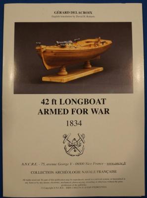
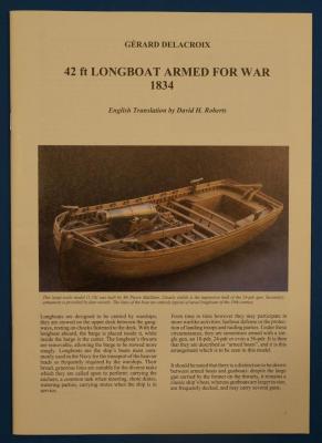
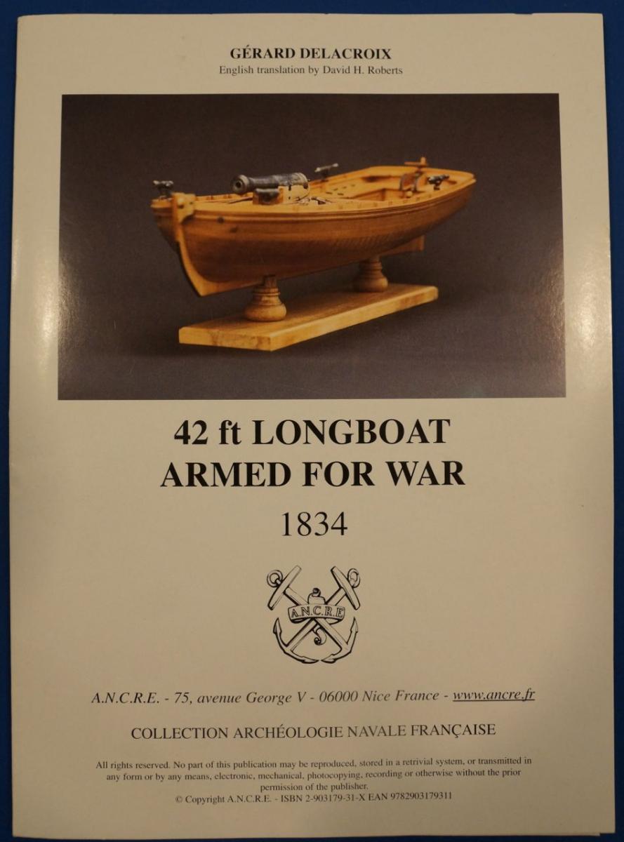
My next project is the Chaloupe Armee en Guerre or Longboat Armed for War. This will be a scratch-built model at a scale of 1:36, from the plans available here: http://www.ancre.fr/vaisso25.htm.
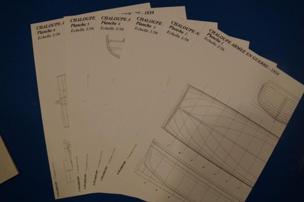
I ordered my copy of the monograph and plans direct from ANCRE and they came speedily and at a very reasonable rate of postage. This is the first publication from ANCRE that I have seen, and I must say I'm impressed. The six sheets of plans are drawn beautifully and the accompanying booklet, which describes the boat and the construction process, is very well laid out. There are many illustrations of the construction process, as well as detail photos of a 1:18 version of the same boat. I should note that the original text was in French and has been translated into English by David H Roberts, who has done an excellent job.
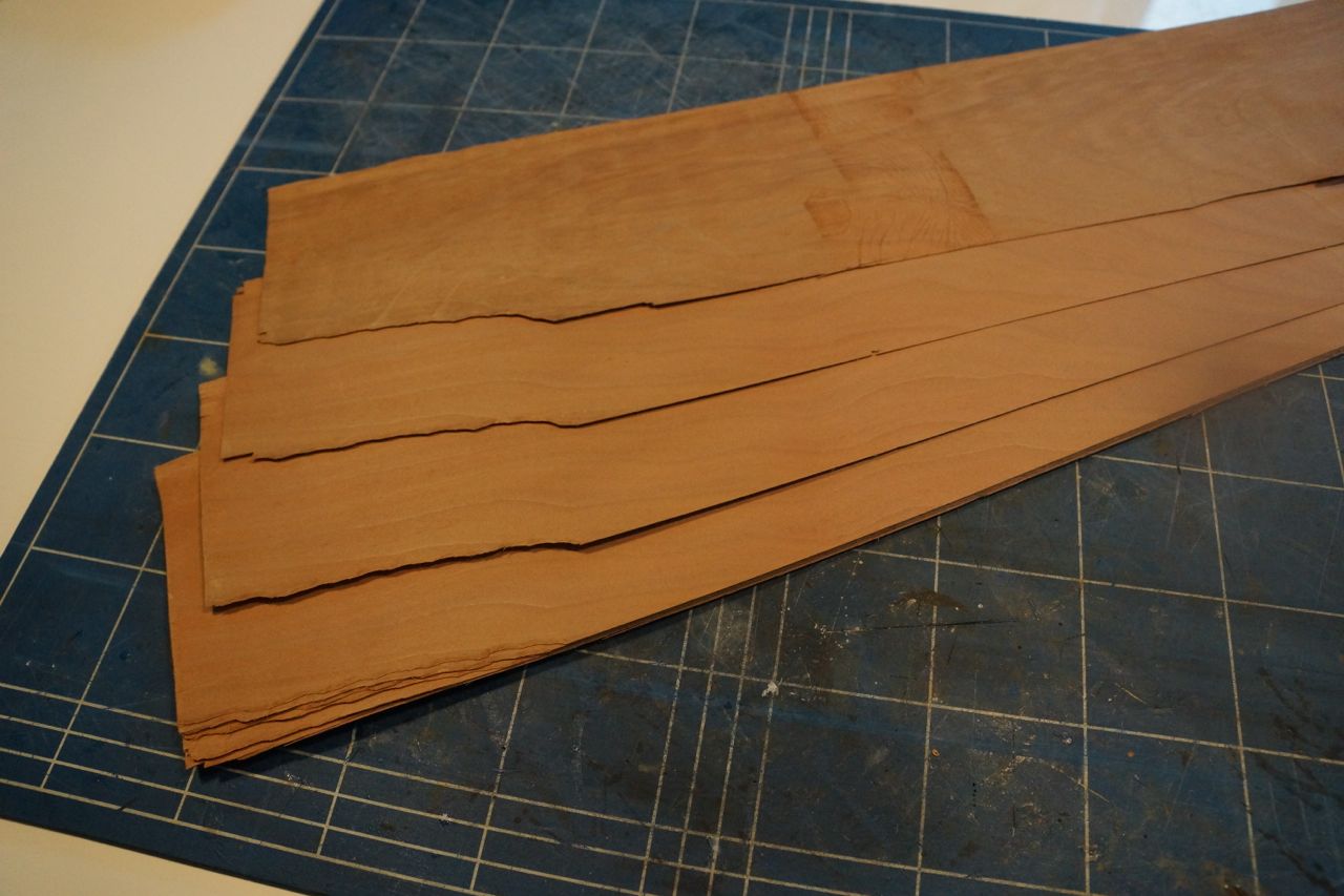
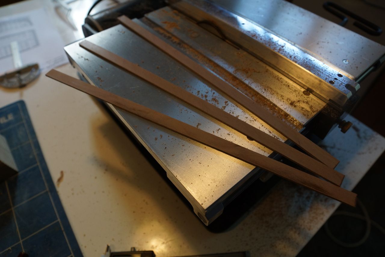
Whilst finishing my Agamemnon (http://modelshipworld.com/index.php?/topic/1115-hms-agamemnon-by-decoyman-caldercraft/) I have been collecting pieces of wood I thought might be useful when scratch-building. I discovered The Toolpost (http://www.toolpost.co.uk), a treasure trove of woodworking equipment, in Didcot, about 15 minutes drive from where I live. They have a good selection of hardwoods and fruitwoods, mostly in turning blanks, as well as a selection of pieces of boxwood of varying sizes. They were also happy to cut every piece I bought into 1" slices on their bandsaw. This means I can now machine them to exact dimensions on my Byrnes table saw, which is a pleasure to use! I haven't finally decided which woods to use where, but I'm starting with apple for the keelson and ribs and will probably use cherry for the planking. I acquired a box full of odd pieces of wood, including a large amount of ebony, from eBay for a very reasonable sum: I might try turning one of the ebony pieces to make the large bow-mounted cannon.
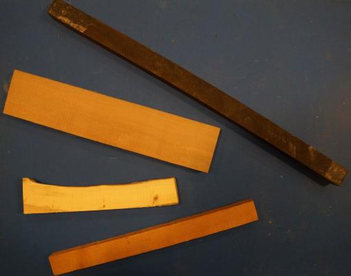
The picture above shows (from the top) ebony, apple, box and cherry.
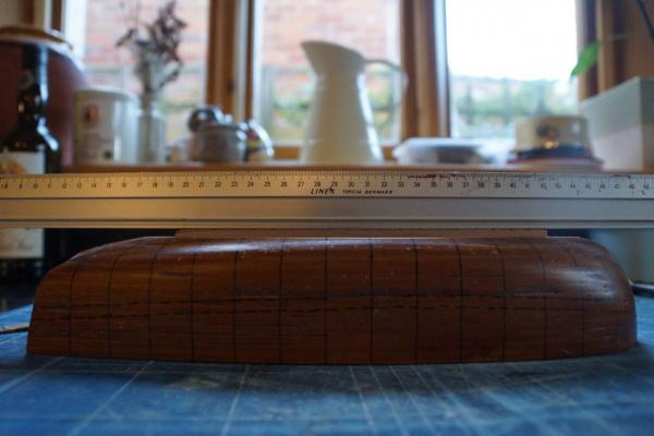
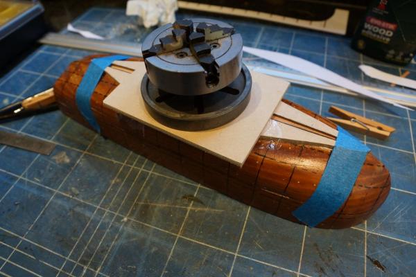
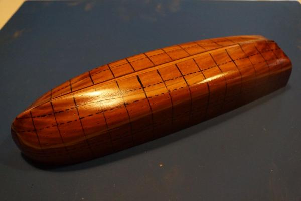
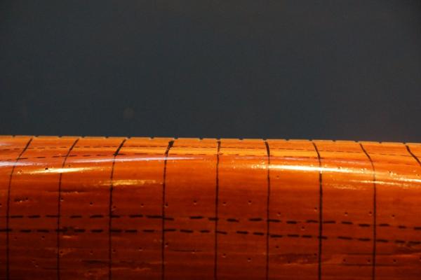
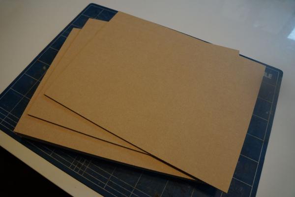
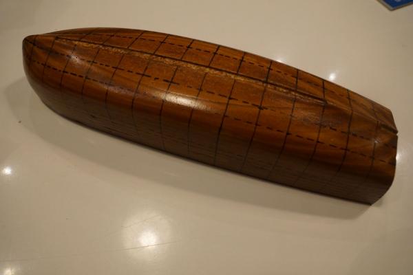
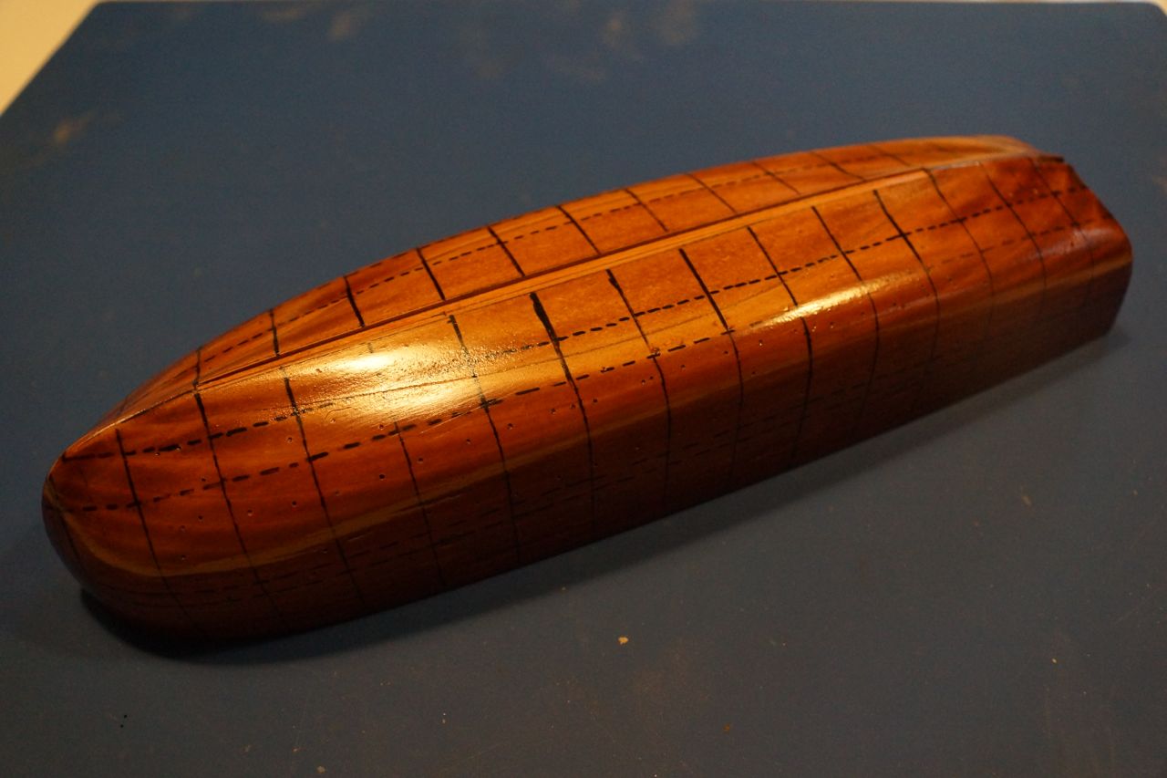
Before I could get going on the good stuff I needed to make a mould, over which the basic hull will be constructed. The instructions say to make this from 5 mm ply, which actually measures nearer to 4.5 mm thick. Unfortunately French plywood is not available in England; here we have 3 mm and 6 mm, which isn't much use. In fact the nearest thing I could find was 4 mm MDF, available on the internet in packets of ten 400 x 300 mm sheets at a reasonable price. This is still not thick enough. The mould is made from layers cut to the shape of the waterlines, if the layers are too thin then the whole boat will end up compressed vertically.
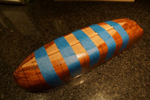
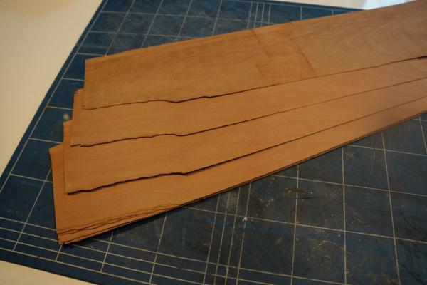
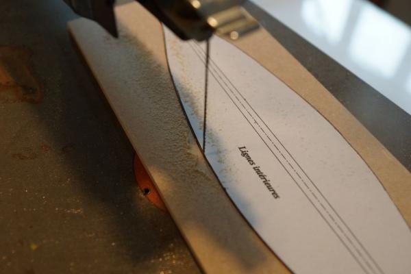
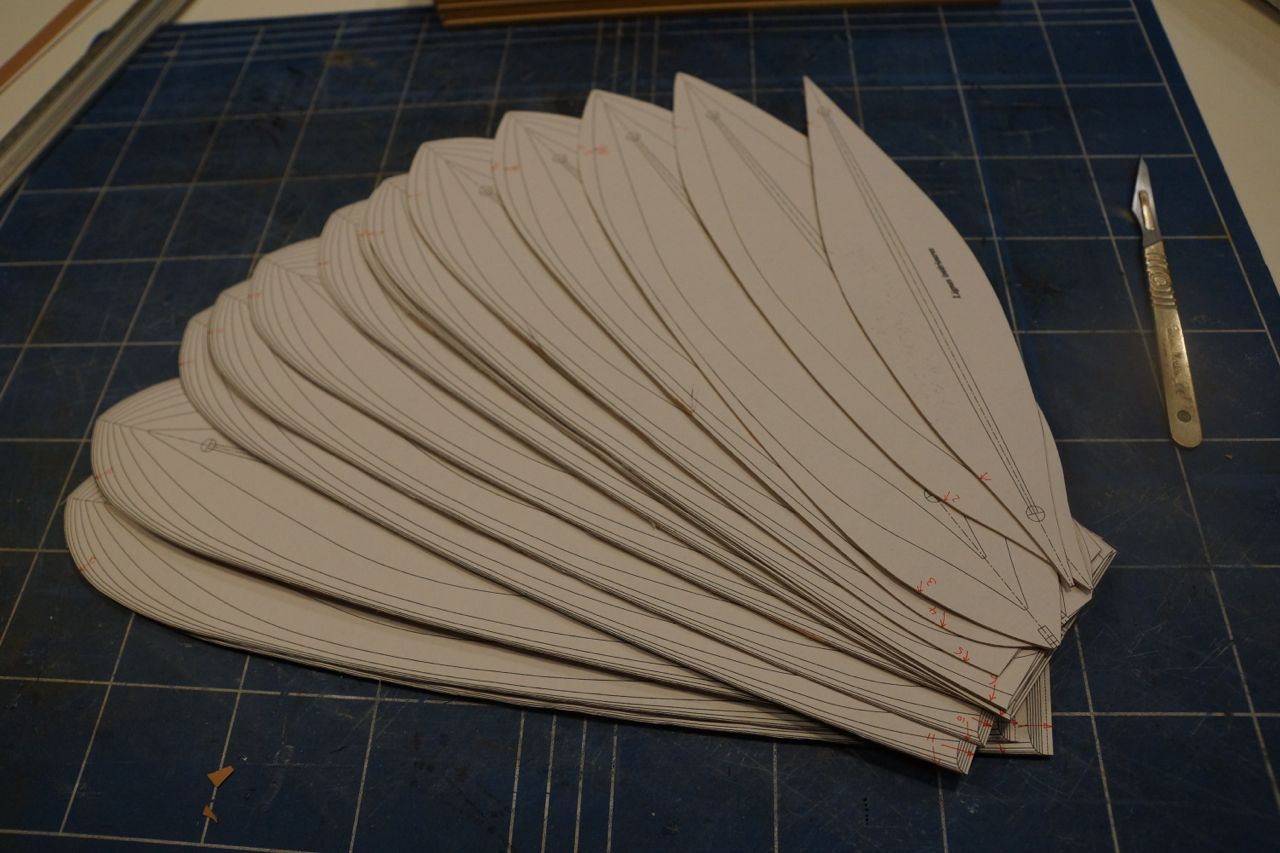
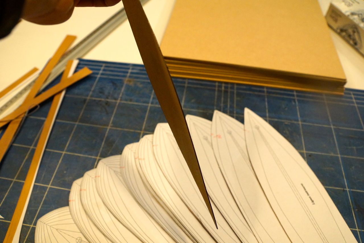
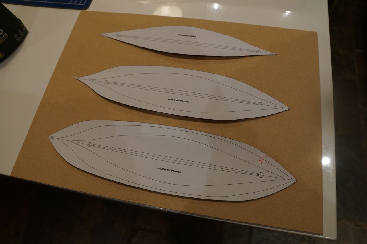
My solution was to interleave the MDF with layers of 0.5 mm cherry veneer, which I happened to have around, so that each layer was 4.5 mm in total. There were some benefits to this method: I could glue photocopies of the plans to each piece of veneer and then cut out each layer accurately using a scalpel. Once that was done I coloured the edges with a black permanent marker. This was so when I sanded the mould to its finished profile I knew that when I reached the black I was nearly there.
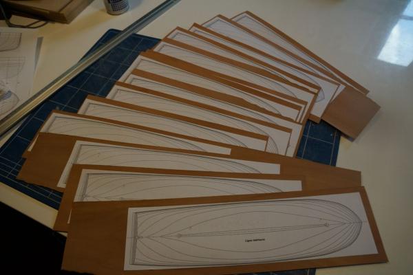
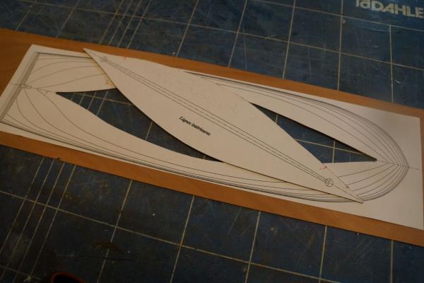
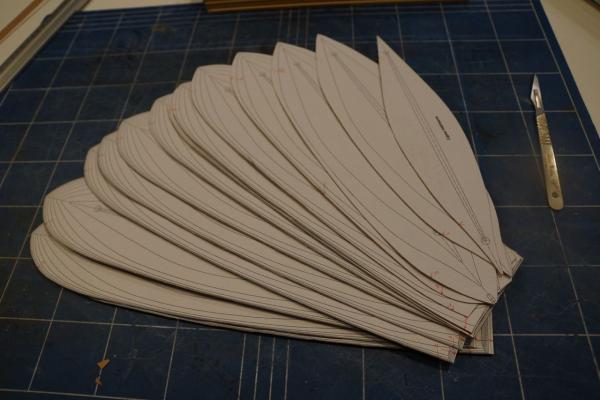

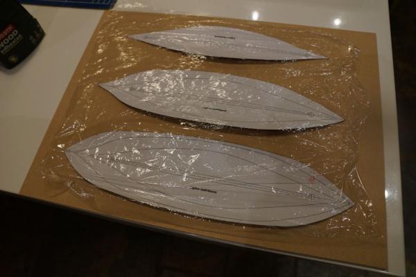
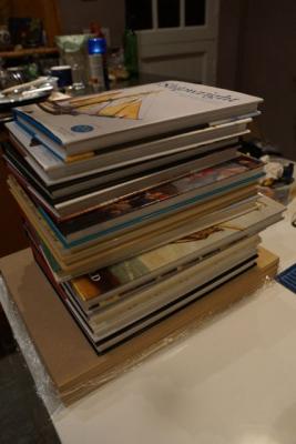
The next step was to glue the veneers to the MDF and remove the photocopies. I left them to dry overnight, interleaved with cling film and weighted down, and then cut each MDF layer out with a fret saw, slightly larger than the veneer stuck to the top. Each layer was drilled on the centreline at stations 5F and 5A and then stacked up and glued in order with dowels in the holes to provide alignment. I used dowels instead of the drill bits because I could sand the dowels along with the MDF.

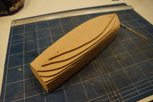
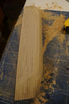
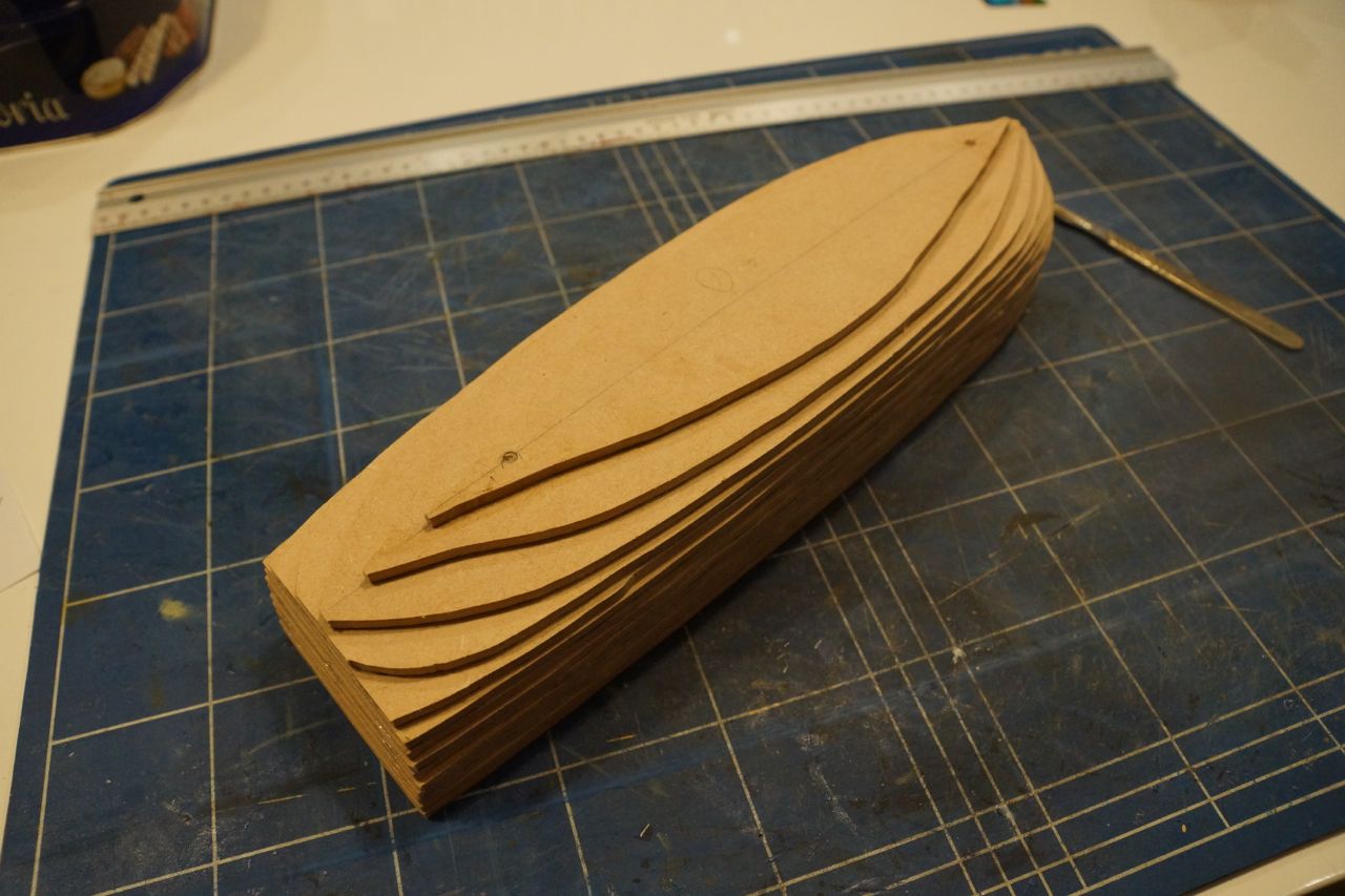
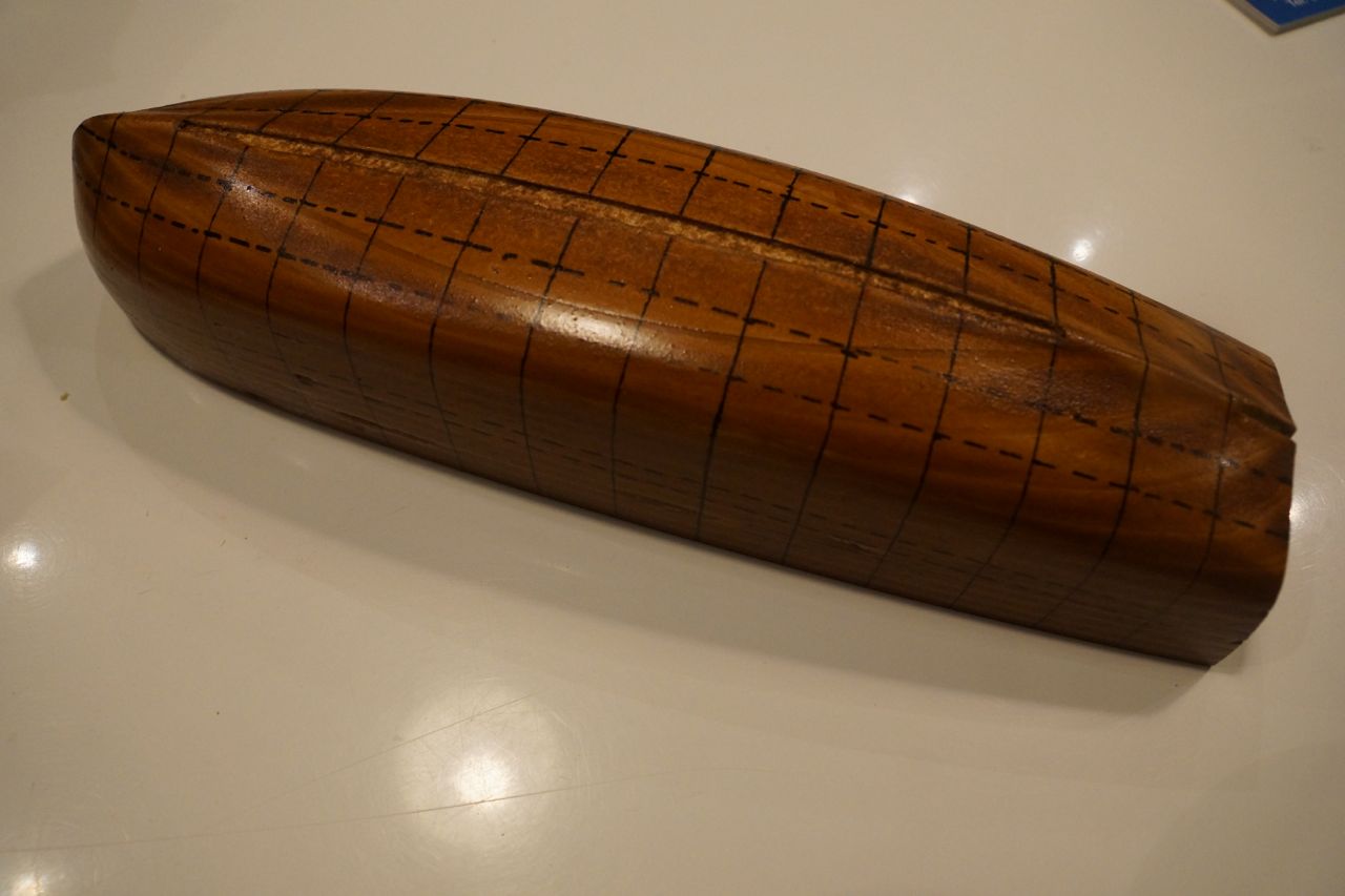
There was a lot of arm-aching sanding to bring the mould to its final form. I used a Surform for quick removal and then coarse sandpaper on a block for accuracy. The end result was pretty accurate but not perfect.
To check the profiles while sanding I glued copies of the frame profiles to 1.2 mm card, as well as the keel. I used these to check I was getting the shape right, but I also cut them so they would slot together. Once the mould fitted all the card frames and the keel I was just about done!
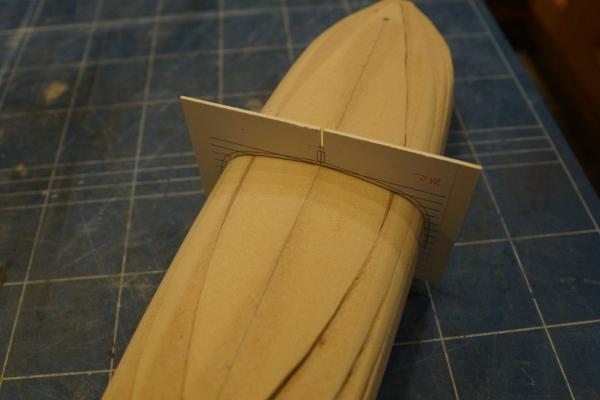
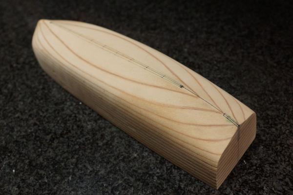
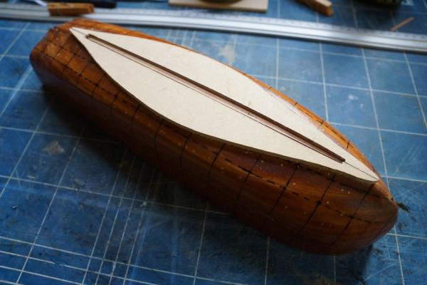
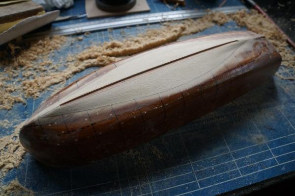
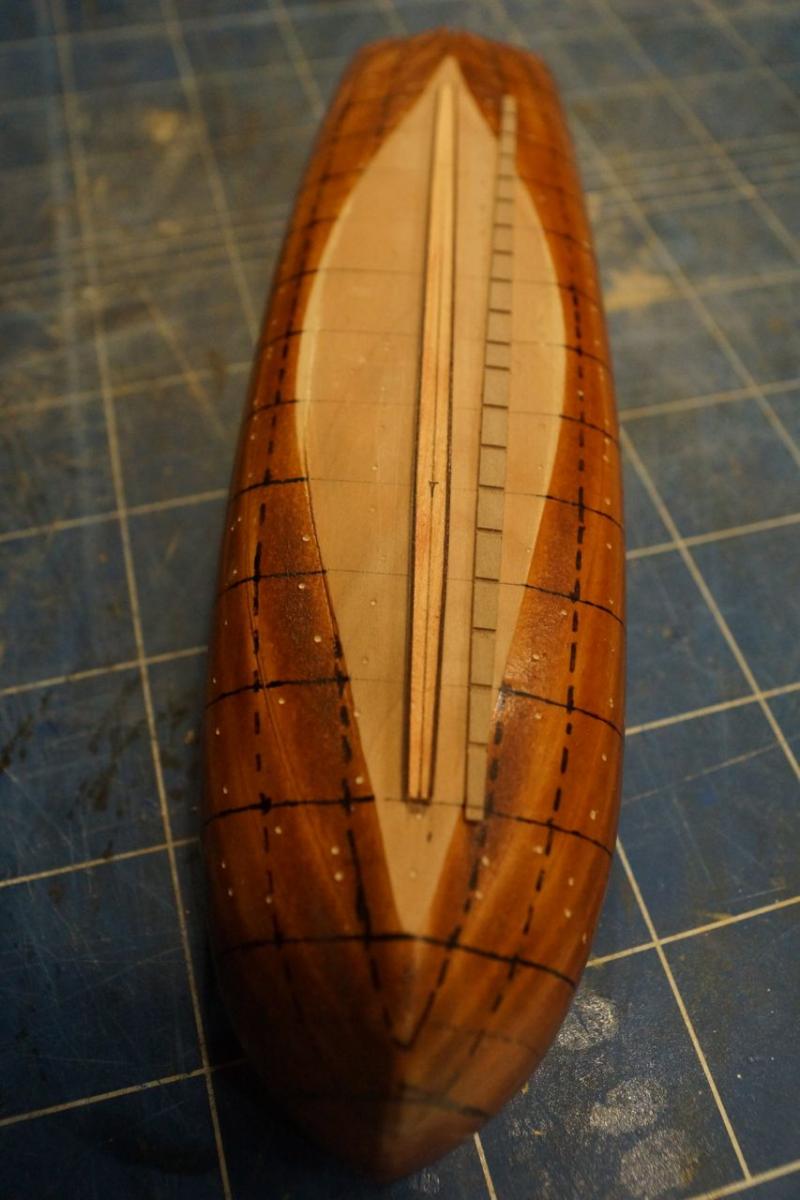
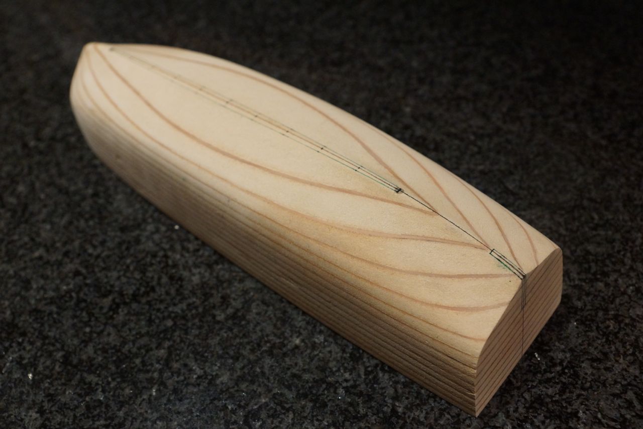
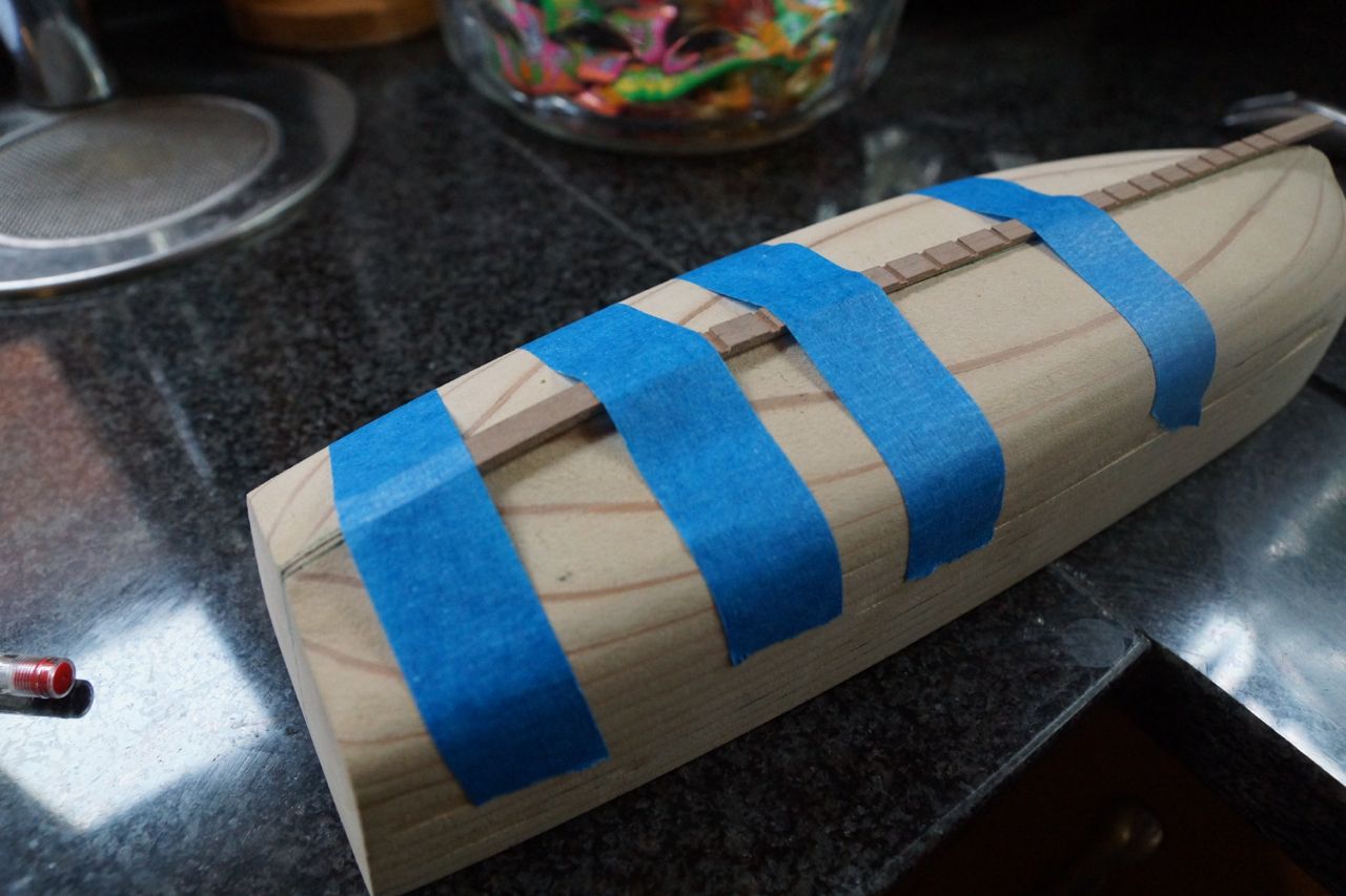
In the last of the photos above you can see marking out for the recesses to take the keelson and the knee of the stern. To ensure the keelson recess was the right size I made a start on this piece. It's cut from a piece of 2.3 x 6 mm apple on the table saw, which I also used to cut the rebates for the frames. It curves up towards the stern so I soaked it in hot water for a while, then taped it to the mould.

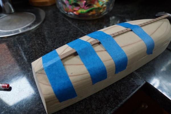

Once the keelson had the correct profile I used it to adjust the recess in the mould. The last thing to finish the mould were two coats of varnish and a polish. The purpose of this is to protect the markings showing the frames and the wales and to try to stop the glue sticking the frames to the mould. We'll see how we get on with this in due course.
In the meantime the next task is to bend the frames round the mould.
More soon!
Rob
- mtaylor, gjdale, aykutansin and 6 others
-
9
-
I think this comment might be fairly obvious, but the fact of the matter is I'm having trouble maintaining my enthusiasm for rebuilding my Agamemnon log.
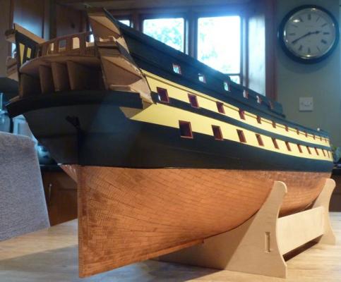
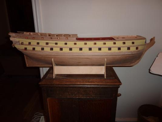
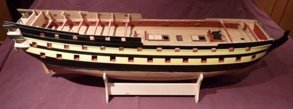
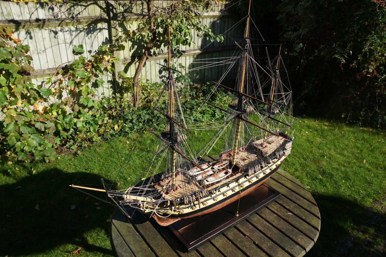
However, despite the lack of evidence and a coherent storyline… I have actually finished! The whole thing!! It's taken me 11 years, 2 months and 3 days exactly. I have no idea how many hours I have spent on it, but it's a lot. The entire build was done on our kitchen table, which meant having to clear away before every meal and share it with my children when they did their homework. There are two lights hung quite low above the table, and when I got to the masting stage I bashed them nearly every time I moved the model from the top of the piano to the kitchen. Nevertheless she's still in one piece. Here are a couple of pictures:
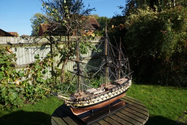

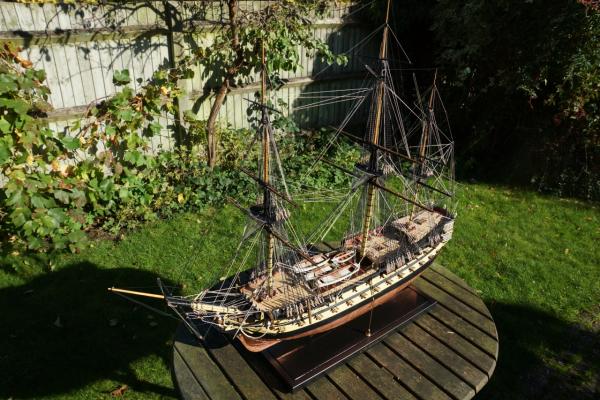
She's very difficult to photograph most of the time because either she's against a wall, which results in an overlay of confusing shadows, or she's on the table with the lights in the picture and the kitchen clutter in the background. I took her out into the garden for the final shots, but even that isn't perfect. I'm considering getting some professional pictures taken in a studio, but for that I'll need a car with a higher roof.
I hope you like it!
Rob
- alangr4, mtaylor, Duanelaker and 13 others
-
16
-
The next step was to fit the dummy cannons on the lower gun deck. I chose to blacken the metalwork using Carrs Metal Black for Brass. I found that, even after cleaning the larger pieces with Surface Conditioner, the blackening wouldn't always take first time, but a second clean and another dip into the blackening bath seemed to work. Here is a picture of progress part way through blackening the dummy barrels.
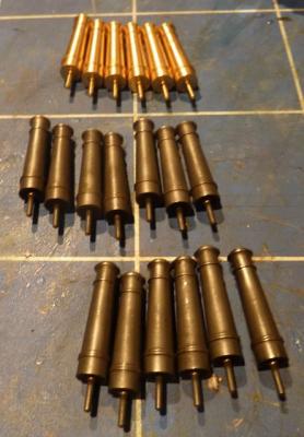
The blackened barrels have been polished with a piece of kitchen towel after cleaning off the solution. They're still a bit uneven and I'm not sure I would choose to blacken them another time. On the other hand I think black paint looks a bit plain, a bit stark and possibly too close in colour to the surrounding planking.
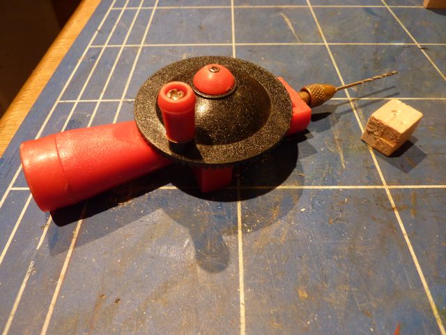
I needed to set the dummy barrels at the same height and horizontal position in each gunport. To help with this I made a guide for my drill. It's only a simple block of balsa of the same height and width as the gun ports, with a hole in the middle for a drill bit. Although the balsa is soft the smooth shank of the bit rubs against it and there are only 28 ports to do, so the hole stays tight enough for the drill not to wander.

The next picture shows some of the dummy barrels in place.

Next the cannons and carriages for the upper gun deck.
Rob
- mtaylor, mobbsie and freewheelinguy
-
3
-
Crackers,
I think your top deadeye is upside-down!
Rob
-
that may be the case - but the point i think they are trying to make is - the work only has to be done once, and once only, then you have mass production of the same thing, no individualityBut that's no different to where we are now, with mass-produced castings. In a kit it's inevitable that mass-produced techniques are needed. With a scratch-build one-offs are needed more often than not, and Seasick is right to point out how much work is involved in creating the computer model before the 3D printed component is produced.
-
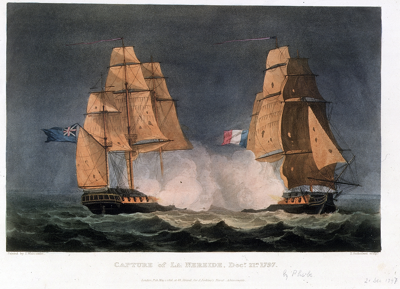
I vote for HMS Phoebe (1795).

She seems to have had her bulwarks raised at some time and there is a model at NMM Chatham (http://collections.rmg.co.uk/collections/objects/66546.html) showing her in this condition, but her original lines look elegant (http://collections.rmg.co.uk/collections/objects/82450.html). There is also a framing drawing available (http://collections.rmg.co.uk/collections/objects/82464.html - useful for the super-detailing?).
She has an interesting and eventful history, including being Nelson's signal ship at Trafalgar (http://en.wikipedia.org/wiki/HMS_Phoebe_(1795)).
Most importantly (for me) she has the same name as my daughter, so I have been toying with making a model of her for some while!
Rob
-
Apologies - I didn't spot that you'd already profiled the gunport lids.
I'm really impressed that all the gunport lids are cut to the correct elevation profile for each opening. That's the way to do it properly!
Rob
-
Great work Chris!
There is an excellent portfolio of Victory photos here: http://picasaweb.google.com/Portchieboy/VictoryReference?authkey=Gv1sRgCOSnmbSV56rtLA. What I noticed in relation to gunport lids is that, although they may in principle be quite thin, in fact the outsides are profiled to follow the profile of the hull. These particular shots illustrate it well:
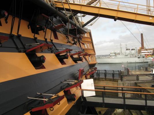
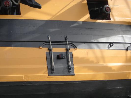
Have you thought about adding timber to the outside to reflect this?
In relation to the gunports I have often wondered if the drip mouldings currently visible over the openings, and which you and others have included in their models, are original or whether they were added once Victory was moved into dry dock to help with the weathering of what are now windows. I don't recall seeing them on contemporary models, but I may be wrong.
Best wishes
Rob
-
For what it's worth I started at the centre of the keel and worked upwards, fore and aft. It worked really well. The best decision I made was to glue a narrow batten around the waterline to finish the plates against.
You can see some photos here: http://modelshipworld.com/index.php?/topic/1115-hms-agamemnon-by-decoyman-caldercraft/page-2
Good luck!
Rob
-
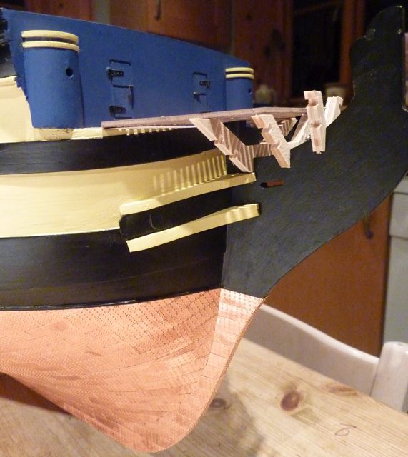
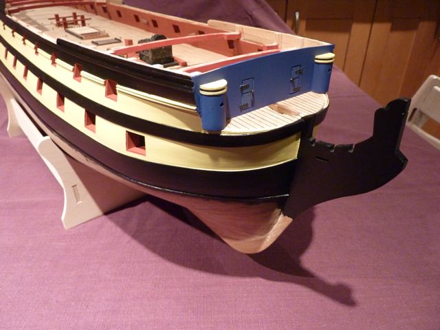
We now get to one of the more interesting parts of the build - the prow. I found this quite fiddly in the way the kit is designed to go together: the V-shaped frames which form the cross-sectional shapes of the headrails are quite clunky, not particularly accurately shaped I suspect, and have quite small details which are cut from a relatively crumbly ply. As a consequence corners tend to fall off. Nevertheless I managed to put everything in place, although I fitted the main head rails too far forward which, once this was pointed out, meant that they had to be redone. In my defence I did follow the plan, but the plan is wrong in this respect. Jotika again came to my rescue by sending me replacement parts.
Here are some progress photos of this area:
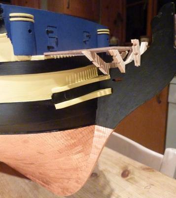
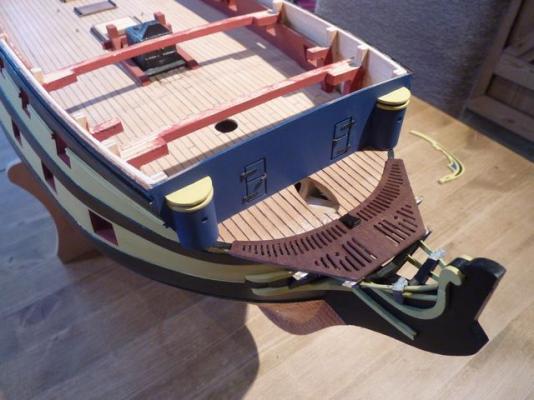
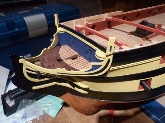
It's not entirely obvious, but the head rails are too far forward in the previous shot. In the next shot you can see more clearly that I have now bevelled off the corner of the beakhead bulkhead and temporarily clamped a replacement rail in place.
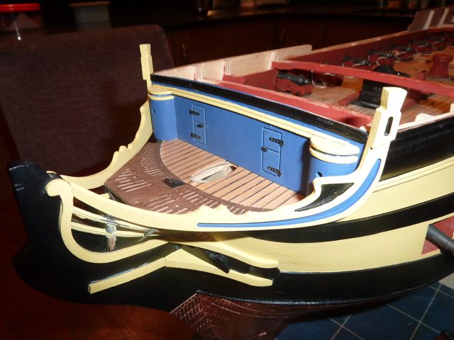
Finally here is a view of the prow with the replacement rails fitted and painted (and looking a lot better). I must say that I have found the constructive criticism offered by the members at MSW very helpful, and I think I am producing a better model as a consequence of their comments. Thank you to everyone who contributed to my previous blog.
I am now off to finish fitting the mizzen topsail yard. More later.
Rob

-
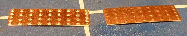
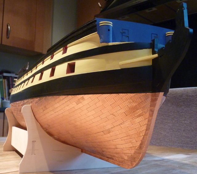
The next stage was the coppering of the hull. The plates supplied with the kit are easy to use, although they are not strictly prototypical as they don't overlap each other. I used thick CA in a blob on the back of the plate which, when the plate was applied to the hull, spread out just enough to stick firmly. It also stayed loose long enough to allow the plate to be slid exactly into position. The relatively small size of the plates meant that smooth lines of plates could be made without generating unsightly gaps as I progressed around the hull.
Some of the plates weren't embossed properly, judging by the way these mostly came stuck together, I suspect they had gone through the embossing machine in pairs. However there were so many spare that this wasn't a problem. In the following photo the one on the right has not come out properly; the one on the left is fine.

Where cuts were necessary I was able to score the plate along a straight-edge and then flex it until the two halves came apart.
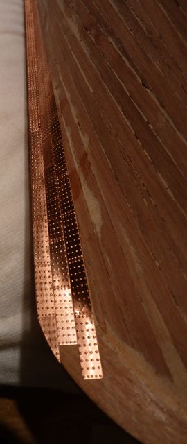
I started along the keel and worked my way up to the waterline.

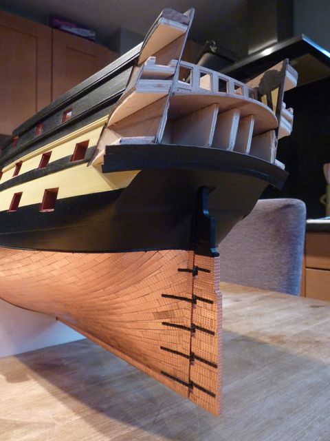
Here are some views of the completed job. You can see how the plates mostly adjusted themselves around the three dimensional shape of the hull; only a couple of rows of stealers were needed at the stem and stern.

I also coppered the rudder and blackened the hinges. I was subsequently told that the straps should be copper, so I will have to paint these using copper paint as part of the final snagging when I am provisionally finished.

- ccoyle, GrandpaPhil and yvesvidal
-
3
-
Ok - I've been stung back into action!
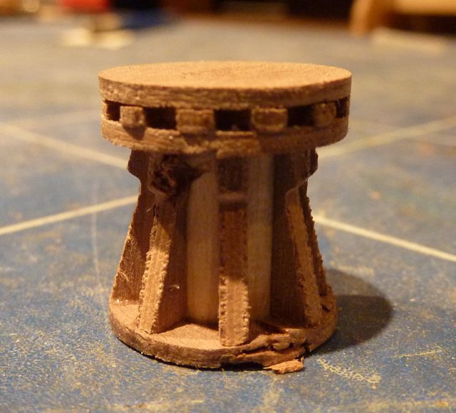
My last post was about the making of the ship's ladders. Fitting these completed most of the work to the 'structure' of the main gun deck. The only other major fixed component was the capstan. The pre-cut components fitted together well, but I rather stupidly decided to spin the completed unit in my lathe to tidy up the edges. Oops! The bit cut into the relatively soft timber and chewed it up in moments. As I recall it looked worse in real life than it does in this photo.
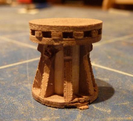
Fortunately a call to Jotika resulted in replacement parts at no cost (thank you Jotika), so I was able to rebuild it, this time successfully.
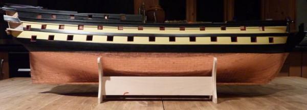
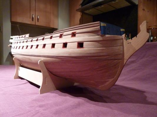
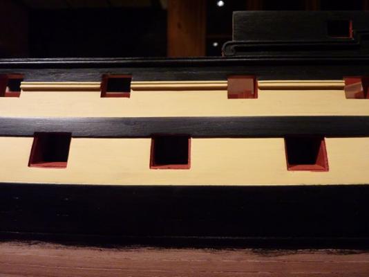
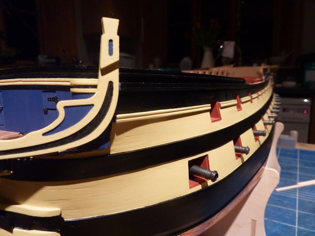
The next stage was to paint the hull as far as was necessary to be able to start the coppering. I installed a thin (0.5 x 0.5 mm walnut) strip at the waterline to make a neat stop for the top edge of the copper plates. I painted the insides of the gun ports red first, then between the wales in yellow. Finally I painted the rest of the exterior satin black. I used Humbol colours exclusively. The yellow is no. 74 - Linen, which is much paler and less orange than the ochre currently used on Victory and which seems very popular elsewhere on this site. Personally I prefer the less strident colour palette achieved with this choice. Others may think differently, of course.
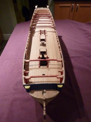
A general view of the upper gun deck (at this stage the first capstan is temporarily in place).
Here you can see the waterline strip and the painting of the gun ports.
This photo shows the yellow bands after the first coat. As I recall it took at least three coats, rubbing down carefully between coats, to get a good, opaque finish.

And finally some shots of the exterior with the rest painted black. There was a small amount of retouching to be done, but by this stage I was pretty pleased with the quality.
-
I'm still here!
Unfortunately (from the MSW point of view) I have rather more stamina for building the model than for resurrecting my build log. I'd better try to put some of that right....
In case anyone is interested I'm currently installing the yards. I've done all the lower ones and am working on the mizzen topsail. This means I've done all the standing rigging and quite a lot of the running rigging. I'm making the yards as I go, which means I have four which I haven't yet started. I also have to make and install the anchors, make all the rope coils and tidy everything up from stem to stern. However I think the end is in sight (nearly eleven years after I started).
Thanks for your interest!
Rob
-
I've long been itching to try out building this particular ship and draw my own bulkheads by re-scaling the AOTS plans to 1/64 and offsetting each station by 1.5mm inward to make up for planking thicknessI don't think you need to offset the lines: as drawn they represent the outside of the frames/inside of the planking.
Rob
-
Michael,
I am impressed! Simple tools with a good result - just what I wanted. I'll be out in the garden this weekend giving it a go - thank you!
Regards
Rob
-
Hi All,
Back in the dim, distant days of MSW 1.0 Jim Byrnes kindly donated one of his table saws, to be sold to the first person who offered the suggested amount. Well, I won!
Last week the saw finally arrived - what a work of art! Can I just say thank you to everyone from Jim to the site moderators.
All I have to do now is find some suitable, decent wood to slice up into small pieces. I can hardly wait!
Best wishes
Rob
-
Hi 42rocker,
I have a small chainsaw and a brand new Byrnes table saw. Also a selection of handsaws of various types and sizes, including a bow saw. However slicing logs lengthways with any of these will be effectively impossible (which is why I contacted the mill). My thoughts were to slice the logs into roughly 25 mm planks, probably quarter-sawn.
Once I have the 25 mm planks I can store them in my loft for a year or so to dry. After that I can slice them to suitable modelling sizes using the Byrnes saw.
I wondered about buying wood in locally, but the only common timber around here is beech, which I don't like for it's grain, hardness and general unsuitability for small pieces. At least that's my opinion.
Perhaps my logs will have to be firewood after all (cutting into small logs is easy with the chain saw)....
Rob


Chaloupe Armee en Guerre by Decoyman - from the Delacroix plans
in - Build logs for subjects built 1801 - 1850
Posted · Edited by Decoyman
Thanks for the advice chaps!
I'm thinking about Ron's test suggestion and, short of making another mould, I haven't thought of a quick way yet.
I don't know if I mentioned it before, but I have polished the surface of the mould with a wax-based spray. Hopefully this will help too, however I don't want it too waxy since it might affect the surface of the ribs.
The instructions suggest that a frame inadvertently glued to the mould can be freed by giving it a sharp tap with a hammer against a block of wood placed alongside the frame. I think this might be my first test.
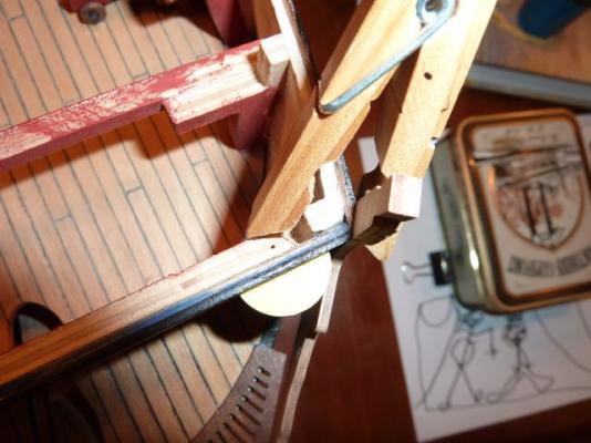
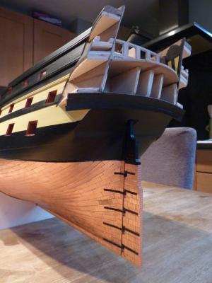
In the meantime I have been making the 'spine' of the boat; that is: the keel, the stem, the sternpost, the apron, the deadwood and the knee. This took two goes: the first keel was too long and I had already cut the rebate for the sternpost, so I couldn't shorten it. I had made the half-lapped joint between the stem and keel, but nothing else. This at least was good practice for the second attempt! I think the keel was too long because the paper pattern, which I glued to the cherry blank, stretched when it was wet with the glue.
The second time I made two changes: I left the keel over length at the stern to start with so it could be cut down later, and I cut a mortice for the sternpost, rather than a rebate since this looked more in line with the prototype illustrations (despite the drawings, which show a rebate).
This project is a big learning exercise for me, especially with the use of my new Byrnes table saw (thank you again MSW!). I have no thicknesser yet, so I am reliant on the fine blade in the saw to get a good, parallel-sided finish on the wood. In practice this means that the widest I can make a plank is about 24 mm, cutting from both sides. Fortunately this is just enough for the curve of the apron.
The first image shows all the blanks rough cut and roughly in the right relationship. As many of the straight cuts as possible have been made with the table saw. The remainder will be cut using a fretsaw.
The next picture shows the stern components after they have been cut and sanded to the right profile. I made a rudimentary 'bobbin' sander with a piece of MDF with a hole fixed to the bed of my pillar drill and a sanding drum in the chuck. It's actually very effective and accurate. I use this for all the concave curves and a hand sanding block with a shooting board for the convex and straight faces.
I fixed the apron to the stem and keel prior to cutting out the inner curve. This was because I thought such a thin piece of partially-crossgrained timber might break when I tried to cut it or sand it. Fixing it to the other members made it stronger.
Finally some shots of all the components assembled and sanded. No too shabby for a beginner!
When the glue was well dried I offered the whole thing up to the mould, only to find that the mould was marginally too long. I assume this was for the same reason as the keel being over-length: the paper patterns stretching when glued. My solution is to sand off the back face of the transom. I'll let you all know how I get on in my next report!
Rob