


Decoyman
-
Posts
97 -
Joined
-
Last visited
Reputation Activity
-

 Decoyman got a reaction from aviaamator in HMS Agamemnon by Decoyman - FINISHED - Caldercraft
The other bit of progress achieved before I started my log was to install and plank the upper gun deck. Since then I have made the various fittings, including gratings, bitts and the stove.
Like most kits the gratings come as notched strips like coarse combs. I found the easiest way to assemble these was to fit them together dry and then to dip them in dilute PVA. Once the glue had set I trimmed off the excess timber and sanded the top, bottom and sides. Here are some step by step photos:
Some of the gratings dry-assembled. A 'grid' is made to suit the overall size of each grating:
Next the gratings were dipped in dilute PVA and then the excess dabbed away using kitchen towel:
Finally each grating was trimmed and sanded smooth:
Once this stage was complete I added the coamings around each hatch, some of which incorporate the openings for the companionways between decks.
Here is an example of one in situ. The corners were cut square and butted. I believe the real ones were half-lapped at the corners, but I didn't think this would be visible at this scale.
And here are a few more. On some of these you can see that i have added shot garlands along the sides.
Rob
-
 Decoyman got a reaction from fatih79 in Chaloupe Armee en Guerre by Decoyman - from the Delacroix plans
As you may have noticed I have not made any posts for a while. Pressure of work and now a new job have all made work on my chaloupe nigh on impossible, sadly. I do have some progress which I have not yet reported on and in which you might be interested.
Since my last post I have faired the frames as far as possible. Here are a couple of photos:
However at this stage I began to think something was wrong.... It took me a while, but after much fiddling trying to get the keel, stem and stern posts aligned to each other and square to the mould, I realised that the mould itself was not true. This photo shows the problem:
I think that the stack of MDF laminates was able to slide sideways at the point while the glue was still wet and I was tightening the clamps. I considered sanding the sides square, but concluded that this would only lead to a misshapen mould. So I made a new one, taking more care this time to ensure everything was aligned properly.
Here are the two moulds side-by-side. The differences are not obvious, but the second one is unquestionably more accurate.
Because I had not glued anything to anything else at this stage (with the exception of the floors and futtocks making up each individual frame) I was able to unpin everything from the old mould and re-fix it to the new one. Although the frames had been made over the old mould they fit the new one well enough, so in the end there was not much other than the mould to redo.
So now I was able to make proper forward progress with the transom. You can see the top piece in the picture with all the frames above. This pinned nicely to the back of the sternpost and square to the mould. The next step was to fix two pieces of thin (1.5 mm) ply, roughly profiled to the shape of half the transom, to each side of the stern post, tucked under the top piece. These were pinned in place until the glue was dry. The outer profile was sanded using a round sanding stick running across the last few frames. The outer surface of each side of the transom was boarded with 5 x 1 mm cherry and again the ends were sanded to the correct profile.
The final pieces of progress are the two wales. These needed spiling to the correct longitudinal shape and then profiling in section using a scraper filed into a piece of scrap brass. Once they were soaked and curved to the right plan form they could be glued in place. At this point the framework is strong enough to remove from the mould as you can see.
And that is nearly as far as I have got to date. I have made the two garboard strakes, but they are not finished yet or fitted. Hopefully I will get some more time soon!
Thanks for reading.
Rob
-
 Decoyman got a reaction from ggrieco in Chaloupe Armee en Guerre by Decoyman - from the Delacroix plans
Thanks for the support and the likes everyone!
I have cut the planking rebates in the side of the keel assembly. I used a couple of different scalpel blades: a small straight to cut the inside of the chase and a large curve-ended one to scrape it clean afterwards. Mostly however I used a small V-profile gouge with a very sharp edge. This cuts beautifully and I'm almost happy with the result. The only disappointment was that my very last cut was a wrong'un! I forgot to stop the rebate on the stem and ran it straight out the top. I haven't shown this in the photos below (still feeling slightly annoyed with myself…). My only thought so far is to cut the profile of the short section of extended rebate as neatly as possible and then piece-in a very small sliver of cherry. If anyone has a better idea I'd be pleased to hear it.
I have also made the last frame components. The crutches are over-deep so they can be sanded to shape once the frames are assembled.
Rob
-
Decoyman got a reaction from ggrieco in Chaloupe Armee en Guerre by Decoyman - from the Delacroix plans
As you may have noticed I have not made any posts for a while. Pressure of work and now a new job have all made work on my chaloupe nigh on impossible, sadly. I do have some progress which I have not yet reported on and in which you might be interested.
Since my last post I have faired the frames as far as possible. Here are a couple of photos:
However at this stage I began to think something was wrong.... It took me a while, but after much fiddling trying to get the keel, stem and stern posts aligned to each other and square to the mould, I realised that the mould itself was not true. This photo shows the problem:
I think that the stack of MDF laminates was able to slide sideways at the point while the glue was still wet and I was tightening the clamps. I considered sanding the sides square, but concluded that this would only lead to a misshapen mould. So I made a new one, taking more care this time to ensure everything was aligned properly.
Here are the two moulds side-by-side. The differences are not obvious, but the second one is unquestionably more accurate.
Because I had not glued anything to anything else at this stage (with the exception of the floors and futtocks making up each individual frame) I was able to unpin everything from the old mould and re-fix it to the new one. Although the frames had been made over the old mould they fit the new one well enough, so in the end there was not much other than the mould to redo.
So now I was able to make proper forward progress with the transom. You can see the top piece in the picture with all the frames above. This pinned nicely to the back of the sternpost and square to the mould. The next step was to fix two pieces of thin (1.5 mm) ply, roughly profiled to the shape of half the transom, to each side of the stern post, tucked under the top piece. These were pinned in place until the glue was dry. The outer profile was sanded using a round sanding stick running across the last few frames. The outer surface of each side of the transom was boarded with 5 x 1 mm cherry and again the ends were sanded to the correct profile.
The final pieces of progress are the two wales. These needed spiling to the correct longitudinal shape and then profiling in section using a scraper filed into a piece of scrap brass. Once they were soaked and curved to the right plan form they could be glued in place. At this point the framework is strong enough to remove from the mould as you can see.
And that is nearly as far as I have got to date. I have made the two garboard strakes, but they are not finished yet or fitted. Hopefully I will get some more time soon!
Thanks for reading.
Rob
-
 Decoyman got a reaction from edmay in HMS Agamemnon by Decoyman - FINISHED - Caldercraft
The other bit of progress achieved before I started my log was to install and plank the upper gun deck. Since then I have made the various fittings, including gratings, bitts and the stove.
Like most kits the gratings come as notched strips like coarse combs. I found the easiest way to assemble these was to fit them together dry and then to dip them in dilute PVA. Once the glue had set I trimmed off the excess timber and sanded the top, bottom and sides. Here are some step by step photos:
Some of the gratings dry-assembled. A 'grid' is made to suit the overall size of each grating:
Next the gratings were dipped in dilute PVA and then the excess dabbed away using kitchen towel:
Finally each grating was trimmed and sanded smooth:
Once this stage was complete I added the coamings around each hatch, some of which incorporate the openings for the companionways between decks.
Here is an example of one in situ. The corners were cut square and butted. I believe the real ones were half-lapped at the corners, but I didn't think this would be visible at this scale.
And here are a few more. On some of these you can see that i have added shot garlands along the sides.
Rob
-
 Decoyman got a reaction from Wishmaster in Chaloupe Armee en Guerre by Decoyman - from the Delacroix plans
As you may have noticed I have not made any posts for a while. Pressure of work and now a new job have all made work on my chaloupe nigh on impossible, sadly. I do have some progress which I have not yet reported on and in which you might be interested.
Since my last post I have faired the frames as far as possible. Here are a couple of photos:
However at this stage I began to think something was wrong.... It took me a while, but after much fiddling trying to get the keel, stem and stern posts aligned to each other and square to the mould, I realised that the mould itself was not true. This photo shows the problem:
I think that the stack of MDF laminates was able to slide sideways at the point while the glue was still wet and I was tightening the clamps. I considered sanding the sides square, but concluded that this would only lead to a misshapen mould. So I made a new one, taking more care this time to ensure everything was aligned properly.
Here are the two moulds side-by-side. The differences are not obvious, but the second one is unquestionably more accurate.
Because I had not glued anything to anything else at this stage (with the exception of the floors and futtocks making up each individual frame) I was able to unpin everything from the old mould and re-fix it to the new one. Although the frames had been made over the old mould they fit the new one well enough, so in the end there was not much other than the mould to redo.
So now I was able to make proper forward progress with the transom. You can see the top piece in the picture with all the frames above. This pinned nicely to the back of the sternpost and square to the mould. The next step was to fix two pieces of thin (1.5 mm) ply, roughly profiled to the shape of half the transom, to each side of the stern post, tucked under the top piece. These were pinned in place until the glue was dry. The outer profile was sanded using a round sanding stick running across the last few frames. The outer surface of each side of the transom was boarded with 5 x 1 mm cherry and again the ends were sanded to the correct profile.
The final pieces of progress are the two wales. These needed spiling to the correct longitudinal shape and then profiling in section using a scraper filed into a piece of scrap brass. Once they were soaked and curved to the right plan form they could be glued in place. At this point the framework is strong enough to remove from the mould as you can see.
And that is nearly as far as I have got to date. I have made the two garboard strakes, but they are not finished yet or fitted. Hopefully I will get some more time soon!
Thanks for reading.
Rob
-
Decoyman got a reaction from aviaamator in Chaloupe Armee en Guerre by Decoyman - from the Delacroix plans
Thanks for the support and the likes everyone!
I have cut the planking rebates in the side of the keel assembly. I used a couple of different scalpel blades: a small straight to cut the inside of the chase and a large curve-ended one to scrape it clean afterwards. Mostly however I used a small V-profile gouge with a very sharp edge. This cuts beautifully and I'm almost happy with the result. The only disappointment was that my very last cut was a wrong'un! I forgot to stop the rebate on the stem and ran it straight out the top. I haven't shown this in the photos below (still feeling slightly annoyed with myself…). My only thought so far is to cut the profile of the short section of extended rebate as neatly as possible and then piece-in a very small sliver of cherry. If anyone has a better idea I'd be pleased to hear it.
I have also made the last frame components. The crutches are over-deep so they can be sanded to shape once the frames are assembled.
Rob
-
 Decoyman got a reaction from coxswain in Chaloupe Armee en Guerre by Decoyman - from the Delacroix plans
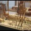
My next project is the Chaloupe Armee en Guerre or Longboat Armed for War. This will be a scratch-built model at a scale of 1:36, from the plans available here: http://www.ancre.fr/vaisso25.htm.
I ordered my copy of the monograph and plans direct from ANCRE and they came speedily and at a very reasonable rate of postage. This is the first publication from ANCRE that I have seen, and I must say I'm impressed. The six sheets of plans are drawn beautifully and the accompanying booklet, which describes the boat and the construction process, is very well laid out. There are many illustrations of the construction process, as well as detail photos of a 1:18 version of the same boat. I should note that the original text was in French and has been translated into English by David H Roberts, who has done an excellent job.
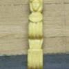
Whilst finishing my Agamemnon (http://modelshipworld.com/index.php?/topic/1115-hms-agamemnon-by-decoyman-caldercraft/) I have been collecting pieces of wood I thought might be useful when scratch-building. I discovered The Toolpost (http://www.toolpost.co.uk), a treasure trove of woodworking equipment, in Didcot, about 15 minutes drive from where I live. They have a good selection of hardwoods and fruitwoods, mostly in turning blanks, as well as a selection of pieces of boxwood of varying sizes. They were also happy to cut every piece I bought into 1" slices on their bandsaw. This means I can now machine them to exact dimensions on my Byrnes table saw, which is a pleasure to use! I haven't finally decided which woods to use where, but I'm starting with apple for the keelson and ribs and will probably use cherry for the planking. I acquired a box full of odd pieces of wood, including a large amount of ebony, from eBay for a very reasonable sum: I might try turning one of the ebony pieces to make the large bow-mounted cannon.
The picture above shows (from the top) ebony, apple, box and cherry.
Before I could get going on the good stuff I needed to make a mould, over which the basic hull will be constructed. The instructions say to make this from 5 mm ply, which actually measures nearer to 4.5 mm thick. Unfortunately French plywood is not available in England; here we have 3 mm and 6 mm, which isn't much use. In fact the nearest thing I could find was 4 mm MDF, available on the internet in packets of ten 400 x 300 mm sheets at a reasonable price. This is still not thick enough. The mould is made from layers cut to the shape of the waterlines, if the layers are too thin then the whole boat will end up compressed vertically.
My solution was to interleave the MDF with layers of 0.5 mm cherry veneer, which I happened to have around, so that each layer was 4.5 mm in total. There were some benefits to this method: I could glue photocopies of the plans to each piece of veneer and then cut out each layer accurately using a scalpel. Once that was done I coloured the edges with a black permanent marker. This was so when I sanded the mould to its finished profile I knew that when I reached the black I was nearly there.
The next step was to glue the veneers to the MDF and remove the photocopies. I left them to dry overnight, interleaved with cling film and weighted down, and then cut each MDF layer out with a fret saw, slightly larger than the veneer stuck to the top. Each layer was drilled on the centreline at stations 5F and 5A and then stacked up and glued in order with dowels in the holes to provide alignment. I used dowels instead of the drill bits because I could sand the dowels along with the MDF.
There was a lot of arm-aching sanding to bring the mould to its final form. I used a Surform for quick removal and then coarse sandpaper on a block for accuracy. The end result was pretty accurate but not perfect.
To check the profiles while sanding I glued copies of the frame profiles to 1.2 mm card, as well as the keel. I used these to check I was getting the shape right, but I also cut them so they would slot together. Once the mould fitted all the card frames and the keel I was just about done!
In the last of the photos above you can see marking out for the recesses to take the keelson and the knee of the stern. To ensure the keelson recess was the right size I made a start on this piece. It's cut from a piece of 2.3 x 6 mm apple on the table saw, which I also used to cut the rebates for the frames. It curves up towards the stern so I soaked it in hot water for a while, then taped it to the mould.
Once the keelson had the correct profile I used it to adjust the recess in the mould. The last thing to finish the mould were two coats of varnish and a polish. The purpose of this is to protect the markings showing the frames and the wales and to try to stop the glue sticking the frames to the mould. We'll see how we get on with this in due course.
In the meantime the next task is to bend the frames round the mould.
More soon!
Rob
-
 Decoyman got a reaction from Allanon in HMS Agamemnon by Decoyman - FINISHED - Caldercraft
I think this comment might be fairly obvious, but the fact of the matter is I'm having trouble maintaining my enthusiasm for rebuilding my Agamemnon log.
However, despite the lack of evidence and a coherent storyline… I have actually finished! The whole thing!! It's taken me 11 years, 2 months and 3 days exactly. I have no idea how many hours I have spent on it, but it's a lot. The entire build was done on our kitchen table, which meant having to clear away before every meal and share it with my children when they did their homework. There are two lights hung quite low above the table, and when I got to the masting stage I bashed them nearly every time I moved the model from the top of the piano to the kitchen. Nevertheless she's still in one piece. Here are a couple of pictures:
She's very difficult to photograph most of the time because either she's against a wall, which results in an overlay of confusing shadows, or she's on the table with the lights in the picture and the kitchen clutter in the background. I took her out into the garden for the final shots, but even that isn't perfect. I'm considering getting some professional pictures taken in a studio, but for that I'll need a car with a higher roof.
I hope you like it!
Rob
-
Decoyman got a reaction from aviaamator in Chaloupe Armee en Guerre by Decoyman - from the Delacroix plans
As you may have noticed I have not made any posts for a while. Pressure of work and now a new job have all made work on my chaloupe nigh on impossible, sadly. I do have some progress which I have not yet reported on and in which you might be interested.
Since my last post I have faired the frames as far as possible. Here are a couple of photos:
However at this stage I began to think something was wrong.... It took me a while, but after much fiddling trying to get the keel, stem and stern posts aligned to each other and square to the mould, I realised that the mould itself was not true. This photo shows the problem:
I think that the stack of MDF laminates was able to slide sideways at the point while the glue was still wet and I was tightening the clamps. I considered sanding the sides square, but concluded that this would only lead to a misshapen mould. So I made a new one, taking more care this time to ensure everything was aligned properly.
Here are the two moulds side-by-side. The differences are not obvious, but the second one is unquestionably more accurate.
Because I had not glued anything to anything else at this stage (with the exception of the floors and futtocks making up each individual frame) I was able to unpin everything from the old mould and re-fix it to the new one. Although the frames had been made over the old mould they fit the new one well enough, so in the end there was not much other than the mould to redo.
So now I was able to make proper forward progress with the transom. You can see the top piece in the picture with all the frames above. This pinned nicely to the back of the sternpost and square to the mould. The next step was to fix two pieces of thin (1.5 mm) ply, roughly profiled to the shape of half the transom, to each side of the stern post, tucked under the top piece. These were pinned in place until the glue was dry. The outer profile was sanded using a round sanding stick running across the last few frames. The outer surface of each side of the transom was boarded with 5 x 1 mm cherry and again the ends were sanded to the correct profile.
The final pieces of progress are the two wales. These needed spiling to the correct longitudinal shape and then profiling in section using a scraper filed into a piece of scrap brass. Once they were soaked and curved to the right plan form they could be glued in place. At this point the framework is strong enough to remove from the mould as you can see.
And that is nearly as far as I have got to date. I have made the two garboard strakes, but they are not finished yet or fitted. Hopefully I will get some more time soon!
Thanks for reading.
Rob
-
 Decoyman got a reaction from Jason in Chaloupe Armee en Guerre by Decoyman - from the Delacroix plans
As you may have noticed I have not made any posts for a while. Pressure of work and now a new job have all made work on my chaloupe nigh on impossible, sadly. I do have some progress which I have not yet reported on and in which you might be interested.
Since my last post I have faired the frames as far as possible. Here are a couple of photos:
However at this stage I began to think something was wrong.... It took me a while, but after much fiddling trying to get the keel, stem and stern posts aligned to each other and square to the mould, I realised that the mould itself was not true. This photo shows the problem:
I think that the stack of MDF laminates was able to slide sideways at the point while the glue was still wet and I was tightening the clamps. I considered sanding the sides square, but concluded that this would only lead to a misshapen mould. So I made a new one, taking more care this time to ensure everything was aligned properly.
Here are the two moulds side-by-side. The differences are not obvious, but the second one is unquestionably more accurate.
Because I had not glued anything to anything else at this stage (with the exception of the floors and futtocks making up each individual frame) I was able to unpin everything from the old mould and re-fix it to the new one. Although the frames had been made over the old mould they fit the new one well enough, so in the end there was not much other than the mould to redo.
So now I was able to make proper forward progress with the transom. You can see the top piece in the picture with all the frames above. This pinned nicely to the back of the sternpost and square to the mould. The next step was to fix two pieces of thin (1.5 mm) ply, roughly profiled to the shape of half the transom, to each side of the stern post, tucked under the top piece. These were pinned in place until the glue was dry. The outer profile was sanded using a round sanding stick running across the last few frames. The outer surface of each side of the transom was boarded with 5 x 1 mm cherry and again the ends were sanded to the correct profile.
The final pieces of progress are the two wales. These needed spiling to the correct longitudinal shape and then profiling in section using a scraper filed into a piece of scrap brass. Once they were soaked and curved to the right plan form they could be glued in place. At this point the framework is strong enough to remove from the mould as you can see.
And that is nearly as far as I have got to date. I have made the two garboard strakes, but they are not finished yet or fitted. Hopefully I will get some more time soon!
Thanks for reading.
Rob
-
 Decoyman got a reaction from tadheus in Chaloupe Armee en Guerre by Decoyman - from the Delacroix plans
As you may have noticed I have not made any posts for a while. Pressure of work and now a new job have all made work on my chaloupe nigh on impossible, sadly. I do have some progress which I have not yet reported on and in which you might be interested.
Since my last post I have faired the frames as far as possible. Here are a couple of photos:
However at this stage I began to think something was wrong.... It took me a while, but after much fiddling trying to get the keel, stem and stern posts aligned to each other and square to the mould, I realised that the mould itself was not true. This photo shows the problem:
I think that the stack of MDF laminates was able to slide sideways at the point while the glue was still wet and I was tightening the clamps. I considered sanding the sides square, but concluded that this would only lead to a misshapen mould. So I made a new one, taking more care this time to ensure everything was aligned properly.
Here are the two moulds side-by-side. The differences are not obvious, but the second one is unquestionably more accurate.
Because I had not glued anything to anything else at this stage (with the exception of the floors and futtocks making up each individual frame) I was able to unpin everything from the old mould and re-fix it to the new one. Although the frames had been made over the old mould they fit the new one well enough, so in the end there was not much other than the mould to redo.
So now I was able to make proper forward progress with the transom. You can see the top piece in the picture with all the frames above. This pinned nicely to the back of the sternpost and square to the mould. The next step was to fix two pieces of thin (1.5 mm) ply, roughly profiled to the shape of half the transom, to each side of the stern post, tucked under the top piece. These were pinned in place until the glue was dry. The outer profile was sanded using a round sanding stick running across the last few frames. The outer surface of each side of the transom was boarded with 5 x 1 mm cherry and again the ends were sanded to the correct profile.
The final pieces of progress are the two wales. These needed spiling to the correct longitudinal shape and then profiling in section using a scraper filed into a piece of scrap brass. Once they were soaked and curved to the right plan form they could be glued in place. At this point the framework is strong enough to remove from the mould as you can see.
And that is nearly as far as I have got to date. I have made the two garboard strakes, but they are not finished yet or fitted. Hopefully I will get some more time soon!
Thanks for reading.
Rob
-
 Decoyman got a reaction from archjofo in Chaloupe Armee en Guerre by Decoyman - from the Delacroix plans
As you may have noticed I have not made any posts for a while. Pressure of work and now a new job have all made work on my chaloupe nigh on impossible, sadly. I do have some progress which I have not yet reported on and in which you might be interested.
Since my last post I have faired the frames as far as possible. Here are a couple of photos:
However at this stage I began to think something was wrong.... It took me a while, but after much fiddling trying to get the keel, stem and stern posts aligned to each other and square to the mould, I realised that the mould itself was not true. This photo shows the problem:
I think that the stack of MDF laminates was able to slide sideways at the point while the glue was still wet and I was tightening the clamps. I considered sanding the sides square, but concluded that this would only lead to a misshapen mould. So I made a new one, taking more care this time to ensure everything was aligned properly.
Here are the two moulds side-by-side. The differences are not obvious, but the second one is unquestionably more accurate.
Because I had not glued anything to anything else at this stage (with the exception of the floors and futtocks making up each individual frame) I was able to unpin everything from the old mould and re-fix it to the new one. Although the frames had been made over the old mould they fit the new one well enough, so in the end there was not much other than the mould to redo.
So now I was able to make proper forward progress with the transom. You can see the top piece in the picture with all the frames above. This pinned nicely to the back of the sternpost and square to the mould. The next step was to fix two pieces of thin (1.5 mm) ply, roughly profiled to the shape of half the transom, to each side of the stern post, tucked under the top piece. These were pinned in place until the glue was dry. The outer profile was sanded using a round sanding stick running across the last few frames. The outer surface of each side of the transom was boarded with 5 x 1 mm cherry and again the ends were sanded to the correct profile.
The final pieces of progress are the two wales. These needed spiling to the correct longitudinal shape and then profiling in section using a scraper filed into a piece of scrap brass. Once they were soaked and curved to the right plan form they could be glued in place. At this point the framework is strong enough to remove from the mould as you can see.
And that is nearly as far as I have got to date. I have made the two garboard strakes, but they are not finished yet or fitted. Hopefully I will get some more time soon!
Thanks for reading.
Rob
-
 Decoyman got a reaction from tlevine in Chaloupe Armee en Guerre by Decoyman - from the Delacroix plans
As you may have noticed I have not made any posts for a while. Pressure of work and now a new job have all made work on my chaloupe nigh on impossible, sadly. I do have some progress which I have not yet reported on and in which you might be interested.
Since my last post I have faired the frames as far as possible. Here are a couple of photos:
However at this stage I began to think something was wrong.... It took me a while, but after much fiddling trying to get the keel, stem and stern posts aligned to each other and square to the mould, I realised that the mould itself was not true. This photo shows the problem:
I think that the stack of MDF laminates was able to slide sideways at the point while the glue was still wet and I was tightening the clamps. I considered sanding the sides square, but concluded that this would only lead to a misshapen mould. So I made a new one, taking more care this time to ensure everything was aligned properly.
Here are the two moulds side-by-side. The differences are not obvious, but the second one is unquestionably more accurate.
Because I had not glued anything to anything else at this stage (with the exception of the floors and futtocks making up each individual frame) I was able to unpin everything from the old mould and re-fix it to the new one. Although the frames had been made over the old mould they fit the new one well enough, so in the end there was not much other than the mould to redo.
So now I was able to make proper forward progress with the transom. You can see the top piece in the picture with all the frames above. This pinned nicely to the back of the sternpost and square to the mould. The next step was to fix two pieces of thin (1.5 mm) ply, roughly profiled to the shape of half the transom, to each side of the stern post, tucked under the top piece. These were pinned in place until the glue was dry. The outer profile was sanded using a round sanding stick running across the last few frames. The outer surface of each side of the transom was boarded with 5 x 1 mm cherry and again the ends were sanded to the correct profile.
The final pieces of progress are the two wales. These needed spiling to the correct longitudinal shape and then profiling in section using a scraper filed into a piece of scrap brass. Once they were soaked and curved to the right plan form they could be glued in place. At this point the framework is strong enough to remove from the mould as you can see.
And that is nearly as far as I have got to date. I have made the two garboard strakes, but they are not finished yet or fitted. Hopefully I will get some more time soon!
Thanks for reading.
Rob
-
 Decoyman got a reaction from 42rocker in Chaloupe Armee en Guerre by Decoyman - from the Delacroix plans
As you may have noticed I have not made any posts for a while. Pressure of work and now a new job have all made work on my chaloupe nigh on impossible, sadly. I do have some progress which I have not yet reported on and in which you might be interested.
Since my last post I have faired the frames as far as possible. Here are a couple of photos:
However at this stage I began to think something was wrong.... It took me a while, but after much fiddling trying to get the keel, stem and stern posts aligned to each other and square to the mould, I realised that the mould itself was not true. This photo shows the problem:
I think that the stack of MDF laminates was able to slide sideways at the point while the glue was still wet and I was tightening the clamps. I considered sanding the sides square, but concluded that this would only lead to a misshapen mould. So I made a new one, taking more care this time to ensure everything was aligned properly.
Here are the two moulds side-by-side. The differences are not obvious, but the second one is unquestionably more accurate.
Because I had not glued anything to anything else at this stage (with the exception of the floors and futtocks making up each individual frame) I was able to unpin everything from the old mould and re-fix it to the new one. Although the frames had been made over the old mould they fit the new one well enough, so in the end there was not much other than the mould to redo.
So now I was able to make proper forward progress with the transom. You can see the top piece in the picture with all the frames above. This pinned nicely to the back of the sternpost and square to the mould. The next step was to fix two pieces of thin (1.5 mm) ply, roughly profiled to the shape of half the transom, to each side of the stern post, tucked under the top piece. These were pinned in place until the glue was dry. The outer profile was sanded using a round sanding stick running across the last few frames. The outer surface of each side of the transom was boarded with 5 x 1 mm cherry and again the ends were sanded to the correct profile.
The final pieces of progress are the two wales. These needed spiling to the correct longitudinal shape and then profiling in section using a scraper filed into a piece of scrap brass. Once they were soaked and curved to the right plan form they could be glued in place. At this point the framework is strong enough to remove from the mould as you can see.
And that is nearly as far as I have got to date. I have made the two garboard strakes, but they are not finished yet or fitted. Hopefully I will get some more time soon!
Thanks for reading.
Rob
-
 Decoyman got a reaction from Mirabell61 in Chaloupe Armee en Guerre by Decoyman - from the Delacroix plans
As you may have noticed I have not made any posts for a while. Pressure of work and now a new job have all made work on my chaloupe nigh on impossible, sadly. I do have some progress which I have not yet reported on and in which you might be interested.
Since my last post I have faired the frames as far as possible. Here are a couple of photos:
However at this stage I began to think something was wrong.... It took me a while, but after much fiddling trying to get the keel, stem and stern posts aligned to each other and square to the mould, I realised that the mould itself was not true. This photo shows the problem:
I think that the stack of MDF laminates was able to slide sideways at the point while the glue was still wet and I was tightening the clamps. I considered sanding the sides square, but concluded that this would only lead to a misshapen mould. So I made a new one, taking more care this time to ensure everything was aligned properly.
Here are the two moulds side-by-side. The differences are not obvious, but the second one is unquestionably more accurate.
Because I had not glued anything to anything else at this stage (with the exception of the floors and futtocks making up each individual frame) I was able to unpin everything from the old mould and re-fix it to the new one. Although the frames had been made over the old mould they fit the new one well enough, so in the end there was not much other than the mould to redo.
So now I was able to make proper forward progress with the transom. You can see the top piece in the picture with all the frames above. This pinned nicely to the back of the sternpost and square to the mould. The next step was to fix two pieces of thin (1.5 mm) ply, roughly profiled to the shape of half the transom, to each side of the stern post, tucked under the top piece. These were pinned in place until the glue was dry. The outer profile was sanded using a round sanding stick running across the last few frames. The outer surface of each side of the transom was boarded with 5 x 1 mm cherry and again the ends were sanded to the correct profile.
The final pieces of progress are the two wales. These needed spiling to the correct longitudinal shape and then profiling in section using a scraper filed into a piece of scrap brass. Once they were soaked and curved to the right plan form they could be glued in place. At this point the framework is strong enough to remove from the mould as you can see.
And that is nearly as far as I have got to date. I have made the two garboard strakes, but they are not finished yet or fitted. Hopefully I will get some more time soon!
Thanks for reading.
Rob
-
 Decoyman got a reaction from Michiel in Chaloupe Armee en Guerre by Decoyman - from the Delacroix plans
As you may have noticed I have not made any posts for a while. Pressure of work and now a new job have all made work on my chaloupe nigh on impossible, sadly. I do have some progress which I have not yet reported on and in which you might be interested.
Since my last post I have faired the frames as far as possible. Here are a couple of photos:
However at this stage I began to think something was wrong.... It took me a while, but after much fiddling trying to get the keel, stem and stern posts aligned to each other and square to the mould, I realised that the mould itself was not true. This photo shows the problem:
I think that the stack of MDF laminates was able to slide sideways at the point while the glue was still wet and I was tightening the clamps. I considered sanding the sides square, but concluded that this would only lead to a misshapen mould. So I made a new one, taking more care this time to ensure everything was aligned properly.
Here are the two moulds side-by-side. The differences are not obvious, but the second one is unquestionably more accurate.
Because I had not glued anything to anything else at this stage (with the exception of the floors and futtocks making up each individual frame) I was able to unpin everything from the old mould and re-fix it to the new one. Although the frames had been made over the old mould they fit the new one well enough, so in the end there was not much other than the mould to redo.
So now I was able to make proper forward progress with the transom. You can see the top piece in the picture with all the frames above. This pinned nicely to the back of the sternpost and square to the mould. The next step was to fix two pieces of thin (1.5 mm) ply, roughly profiled to the shape of half the transom, to each side of the stern post, tucked under the top piece. These were pinned in place until the glue was dry. The outer profile was sanded using a round sanding stick running across the last few frames. The outer surface of each side of the transom was boarded with 5 x 1 mm cherry and again the ends were sanded to the correct profile.
The final pieces of progress are the two wales. These needed spiling to the correct longitudinal shape and then profiling in section using a scraper filed into a piece of scrap brass. Once they were soaked and curved to the right plan form they could be glued in place. At this point the framework is strong enough to remove from the mould as you can see.
And that is nearly as far as I have got to date. I have made the two garboard strakes, but they are not finished yet or fitted. Hopefully I will get some more time soon!
Thanks for reading.
Rob
-
Decoyman got a reaction from archjofo in Chaloupe Armee en Guerre by Decoyman - from the Delacroix plans
Thanks for the support and the likes everyone!
I have cut the planking rebates in the side of the keel assembly. I used a couple of different scalpel blades: a small straight to cut the inside of the chase and a large curve-ended one to scrape it clean afterwards. Mostly however I used a small V-profile gouge with a very sharp edge. This cuts beautifully and I'm almost happy with the result. The only disappointment was that my very last cut was a wrong'un! I forgot to stop the rebate on the stem and ran it straight out the top. I haven't shown this in the photos below (still feeling slightly annoyed with myself…). My only thought so far is to cut the profile of the short section of extended rebate as neatly as possible and then piece-in a very small sliver of cherry. If anyone has a better idea I'd be pleased to hear it.
I have also made the last frame components. The crutches are over-deep so they can be sanded to shape once the frames are assembled.
Rob
-
 Decoyman got a reaction from Aussie048 in Chaloupe Armee en Guerre by Decoyman - from the Delacroix plans
As I suggested in my last post I needed to sand off the end of the mould so that the keel assembly fits properly. This was hard work, but pretty straightforward. As you can see in the following pictures the keel now drops over the frames with no problem.
The next issue was how to stop the frames sticking to the mould when the components were glued together. I took all the frame parts off the mould and gave it another good polish. Then, starting at the MC position, I assembled each frame over the mould, glueing the futtocks to the floors with medium cyano and using the pushpins again to hold everything in the correct relationship. Once the glue was reasonably dry I removed the pins and then the frame. If the frame was stuck I held a piece of wood against the side of the joint and tapped gently until it popped off. Once or twice a frame became glued quite firmly and a bit of the mould came away stuck to the inside. The MDF is actually quite soft, so can be removed easily, and it is certainly better for a bit of the mould to be stuck to the frame rather than a bit of frame stuck to the mould. Occasionally the futtock/floor joint was a bit dry and came apart, in which case I just put everything back on the mould and re-glued the joint.
The small dots on the sides of the floor and futtocks mark the glued faces.
The next step was to drill through the frame joints twice each and insert short lengths of 0.5 mm brass wire. These represent the bolts used on the prototype and also strengthen the joint because they are glued in. Once these were dry I trimmed the over-length floors and futtocks using a razor saw and then rounded off the upper corners in each case. Finally I sanded all the exposed faces, making sure there were no traces of glue left around the joints and the ends of the bolts.
The finished frames were put back onto the mould and pinned in place, making sure the sides were vertical.
I made every other frame to start with so that I had more working room.
I haven't quite finished the frames yet - there are three still to do.
Next time: making the rebates in the sides of the keel and finishing the frames preparatory to fitting the keel.
Rob
-
 Decoyman got a reaction from hexnut in Chaloupe Armee en Guerre by Decoyman - from the Delacroix plans
As you may have noticed I have not made any posts for a while. Pressure of work and now a new job have all made work on my chaloupe nigh on impossible, sadly. I do have some progress which I have not yet reported on and in which you might be interested.
Since my last post I have faired the frames as far as possible. Here are a couple of photos:
However at this stage I began to think something was wrong.... It took me a while, but after much fiddling trying to get the keel, stem and stern posts aligned to each other and square to the mould, I realised that the mould itself was not true. This photo shows the problem:
I think that the stack of MDF laminates was able to slide sideways at the point while the glue was still wet and I was tightening the clamps. I considered sanding the sides square, but concluded that this would only lead to a misshapen mould. So I made a new one, taking more care this time to ensure everything was aligned properly.
Here are the two moulds side-by-side. The differences are not obvious, but the second one is unquestionably more accurate.
Because I had not glued anything to anything else at this stage (with the exception of the floors and futtocks making up each individual frame) I was able to unpin everything from the old mould and re-fix it to the new one. Although the frames had been made over the old mould they fit the new one well enough, so in the end there was not much other than the mould to redo.
So now I was able to make proper forward progress with the transom. You can see the top piece in the picture with all the frames above. This pinned nicely to the back of the sternpost and square to the mould. The next step was to fix two pieces of thin (1.5 mm) ply, roughly profiled to the shape of half the transom, to each side of the stern post, tucked under the top piece. These were pinned in place until the glue was dry. The outer profile was sanded using a round sanding stick running across the last few frames. The outer surface of each side of the transom was boarded with 5 x 1 mm cherry and again the ends were sanded to the correct profile.
The final pieces of progress are the two wales. These needed spiling to the correct longitudinal shape and then profiling in section using a scraper filed into a piece of scrap brass. Once they were soaked and curved to the right plan form they could be glued in place. At this point the framework is strong enough to remove from the mould as you can see.
And that is nearly as far as I have got to date. I have made the two garboard strakes, but they are not finished yet or fitted. Hopefully I will get some more time soon!
Thanks for reading.
Rob
-
 Decoyman got a reaction from sonicmcdude in HMS Agamemnon by Decoyman - FINISHED - Caldercraft
The other bit of progress achieved before I started my log was to install and plank the upper gun deck. Since then I have made the various fittings, including gratings, bitts and the stove.
Like most kits the gratings come as notched strips like coarse combs. I found the easiest way to assemble these was to fit them together dry and then to dip them in dilute PVA. Once the glue had set I trimmed off the excess timber and sanded the top, bottom and sides. Here are some step by step photos:
Some of the gratings dry-assembled. A 'grid' is made to suit the overall size of each grating:
Next the gratings were dipped in dilute PVA and then the excess dabbed away using kitchen towel:
Finally each grating was trimmed and sanded smooth:
Once this stage was complete I added the coamings around each hatch, some of which incorporate the openings for the companionways between decks.
Here is an example of one in situ. The corners were cut square and butted. I believe the real ones were half-lapped at the corners, but I didn't think this would be visible at this scale.
And here are a few more. On some of these you can see that i have added shot garlands along the sides.
Rob
-
 Decoyman got a reaction from tharris in Bomb Vessel Granado by Rustyj - FINISHED - 1:24 - cross-section
No rich uncle I'm afraid. If there was one I'd be first in the queue.
You don't need to turn the blank down to fit in the chuck - just drill a hole in the centre, run a screw in and cut the head off. You can hold the smooth part of the shank of the screw in the chuck.
Rob
-
 Decoyman got a reaction from NMBROOK in Simulated caulking
Haven't you guys got your scale conversation in the wrong topic?
-
Decoyman got a reaction from 42rocker in Chaloupe Armee en Guerre by Decoyman - from the Delacroix plans
Thanks for the support and the likes everyone!
I have cut the planking rebates in the side of the keel assembly. I used a couple of different scalpel blades: a small straight to cut the inside of the chase and a large curve-ended one to scrape it clean afterwards. Mostly however I used a small V-profile gouge with a very sharp edge. This cuts beautifully and I'm almost happy with the result. The only disappointment was that my very last cut was a wrong'un! I forgot to stop the rebate on the stem and ran it straight out the top. I haven't shown this in the photos below (still feeling slightly annoyed with myself…). My only thought so far is to cut the profile of the short section of extended rebate as neatly as possible and then piece-in a very small sliver of cherry. If anyone has a better idea I'd be pleased to hear it.
I have also made the last frame components. The crutches are over-deep so they can be sanded to shape once the frames are assembled.
Rob
-
Decoyman got a reaction from Wishmaster in Chaloupe Armee en Guerre by Decoyman - from the Delacroix plans
As I suggested in my last post I needed to sand off the end of the mould so that the keel assembly fits properly. This was hard work, but pretty straightforward. As you can see in the following pictures the keel now drops over the frames with no problem.
The next issue was how to stop the frames sticking to the mould when the components were glued together. I took all the frame parts off the mould and gave it another good polish. Then, starting at the MC position, I assembled each frame over the mould, glueing the futtocks to the floors with medium cyano and using the pushpins again to hold everything in the correct relationship. Once the glue was reasonably dry I removed the pins and then the frame. If the frame was stuck I held a piece of wood against the side of the joint and tapped gently until it popped off. Once or twice a frame became glued quite firmly and a bit of the mould came away stuck to the inside. The MDF is actually quite soft, so can be removed easily, and it is certainly better for a bit of the mould to be stuck to the frame rather than a bit of frame stuck to the mould. Occasionally the futtock/floor joint was a bit dry and came apart, in which case I just put everything back on the mould and re-glued the joint.
The small dots on the sides of the floor and futtocks mark the glued faces.
The next step was to drill through the frame joints twice each and insert short lengths of 0.5 mm brass wire. These represent the bolts used on the prototype and also strengthen the joint because they are glued in. Once these were dry I trimmed the over-length floors and futtocks using a razor saw and then rounded off the upper corners in each case. Finally I sanded all the exposed faces, making sure there were no traces of glue left around the joints and the ends of the bolts.
The finished frames were put back onto the mould and pinned in place, making sure the sides were vertical.
I made every other frame to start with so that I had more working room.
I haven't quite finished the frames yet - there are three still to do.
Next time: making the rebates in the sides of the keel and finishing the frames preparatory to fitting the keel.
Rob