HOLIDAY DONATION DRIVE - SUPPORT MSW - DO YOUR PART TO KEEP THIS GREAT FORUM GOING! (Only 72 donations so far out of 49,000 members - Can we at least get 100? C'mon guys!)
×


cdrusn89
-
Posts
1,915 -
Joined
-
Last visited
Content Type
Profiles
Forums
Gallery
Events
Everything posted by cdrusn89
-
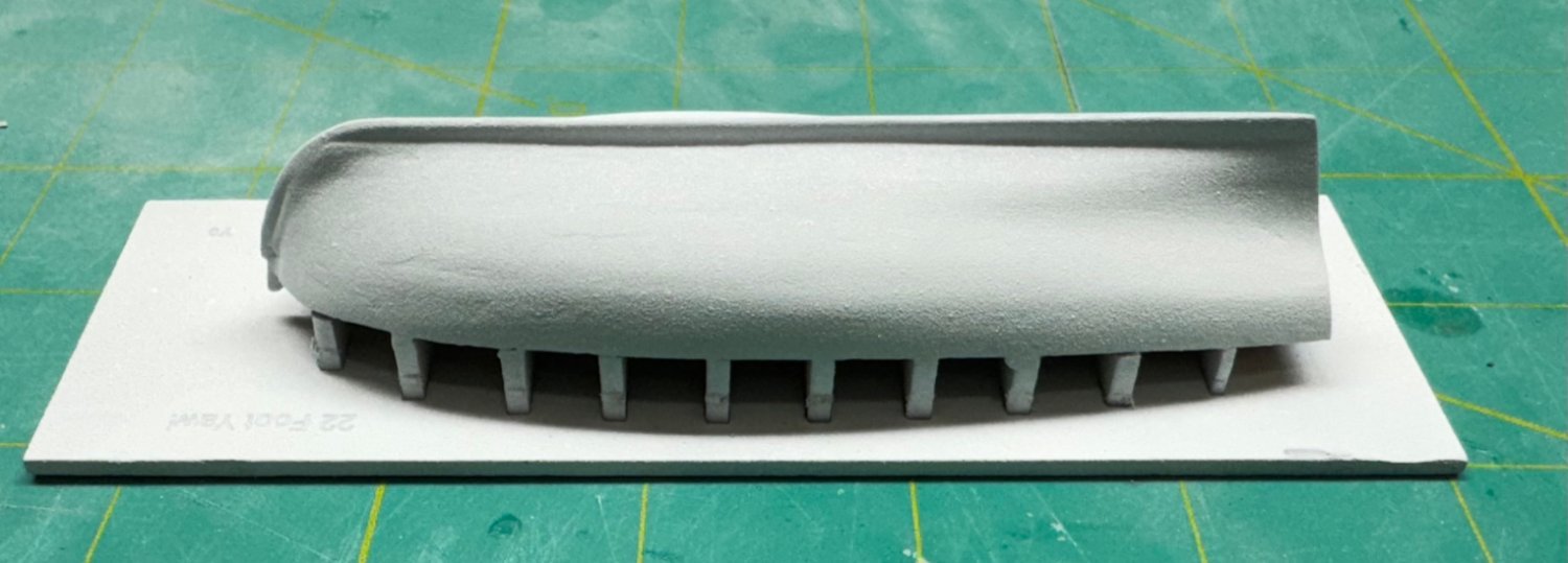
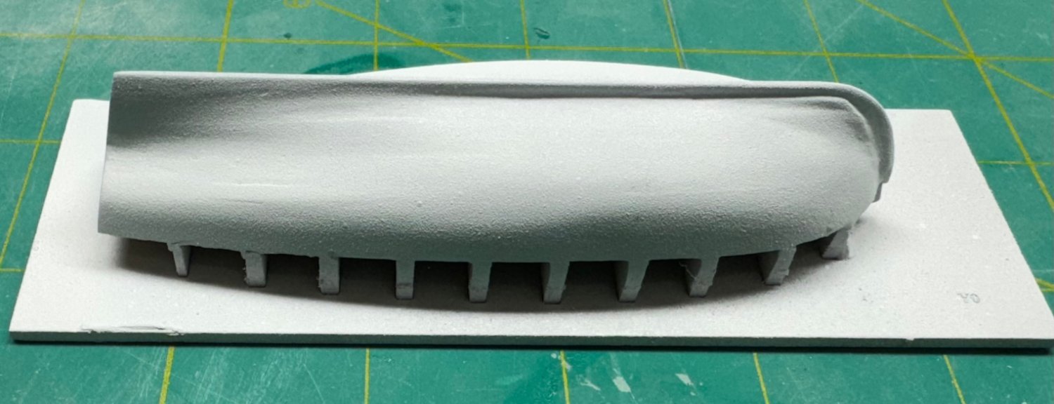
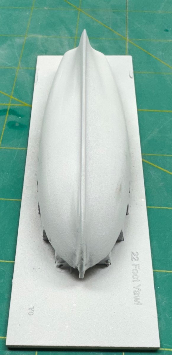
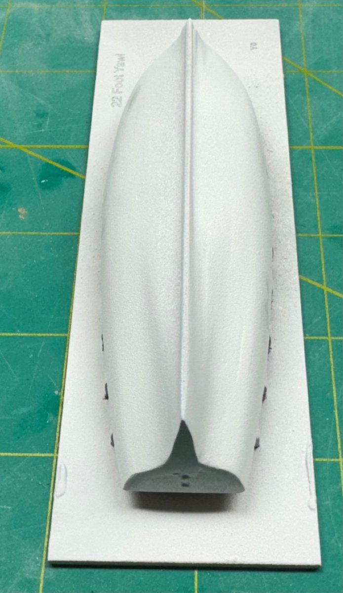
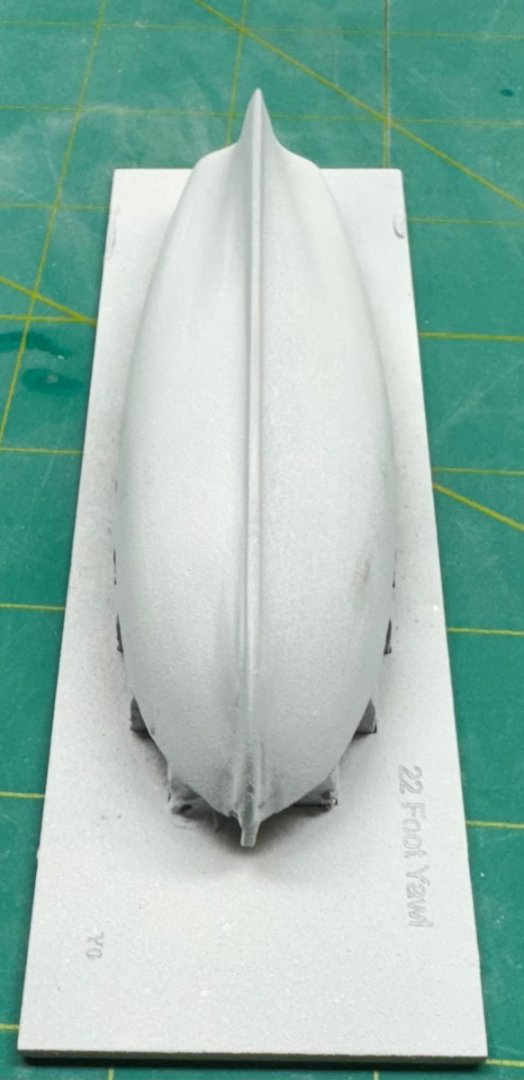
 Back to the yawl. I finally got to a point where I was ready to try a "finish" coat; at least the finish color; flat white. It needs some fine sanding and then another coat but I think it is getting close to time to get it off the building bard and work on the interior.


- 422 replies
-
- 3
-

-
- Vanguard Models
- Sphinx
- (and 1 more)
-
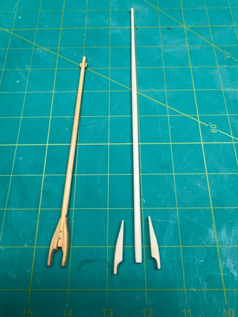
It all started when I broke the gaff during the "dowelerizing" and then could not manage a repair that looked "good enough" since the gaff is going to be quite visible (at least com to the boom). So I cut a new square "blank" from the carrier sheet and proceeded to dowelerize it and then taper to match the drawing. Which leaves the jaws. Although I have only limited personal experience I have seen several gaff rigged sailing vessels at full scale and I believe most (if not all) had the gaff (and boom) jaws as separate pieces rather than the single piece provided in the kit. Easier and cheaper this way no doubt. So I cut the jaws from the provided gaff and cut them as close to in half as I could manage and then sanded the inside to get a very small section at the rear. I cut the new gaff pole to the length shown on the drawing, min us the jaws then flattened two opposing sides and glued (after several rounds of adjustments so they were as nearly symmetrical I as I could get them) the two jaw halves to the gaff. I will add some simulated bolt head (using 30# black monofilament fishing line) before the gaff is mounted. I was so enamored with the process that I decided to do the same thing for the boom. Here is the completed gaff and the boom before final assembly, stain and vanish.
- 88 replies
-
- 4
-
-
- Muscongus Bay Lobster Smack
- Finished
- (and 1 more)
-
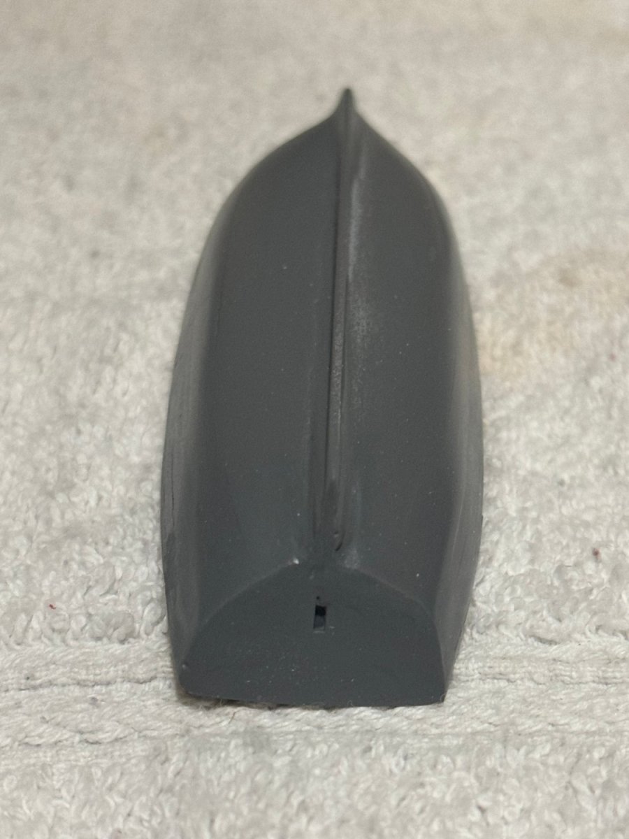
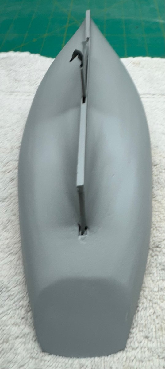
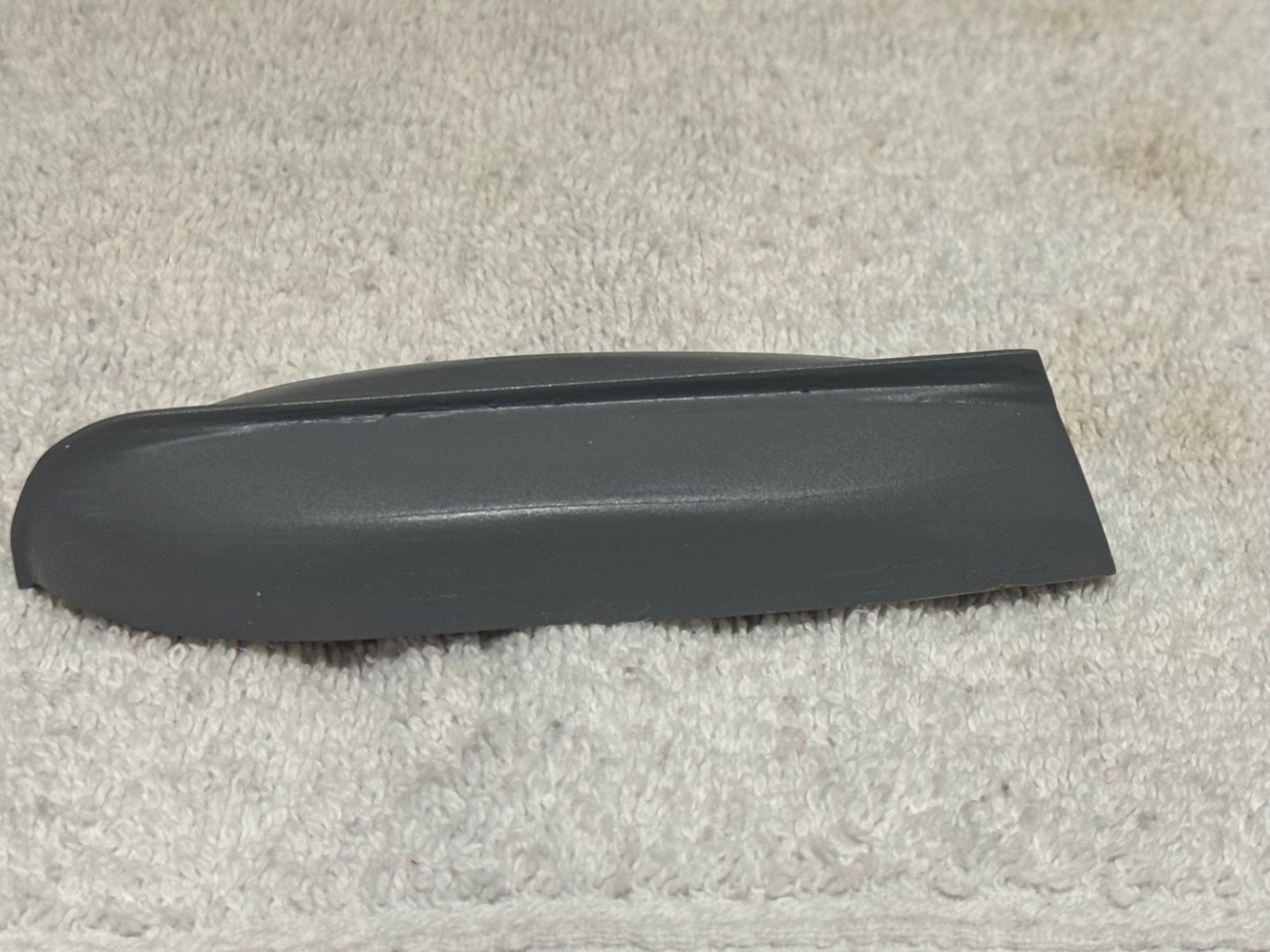
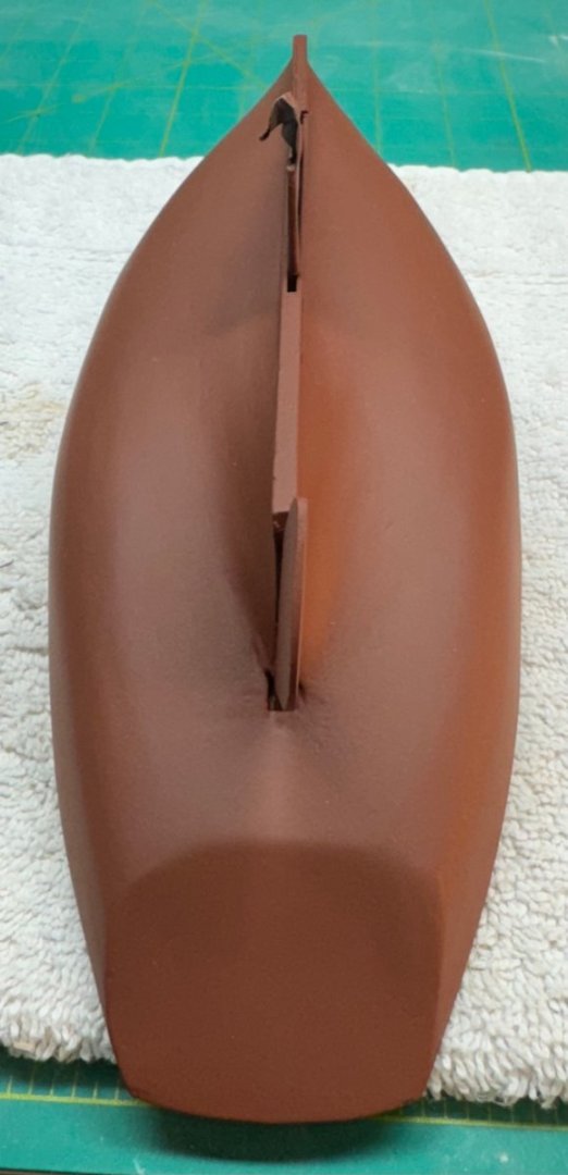
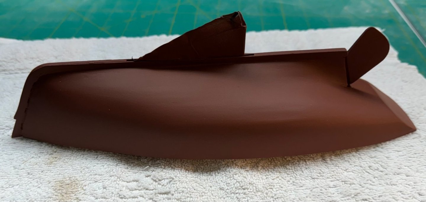
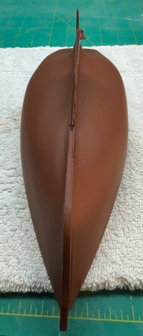
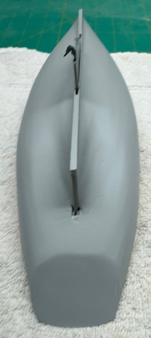
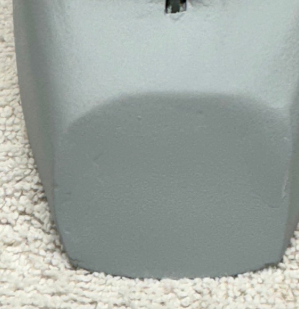
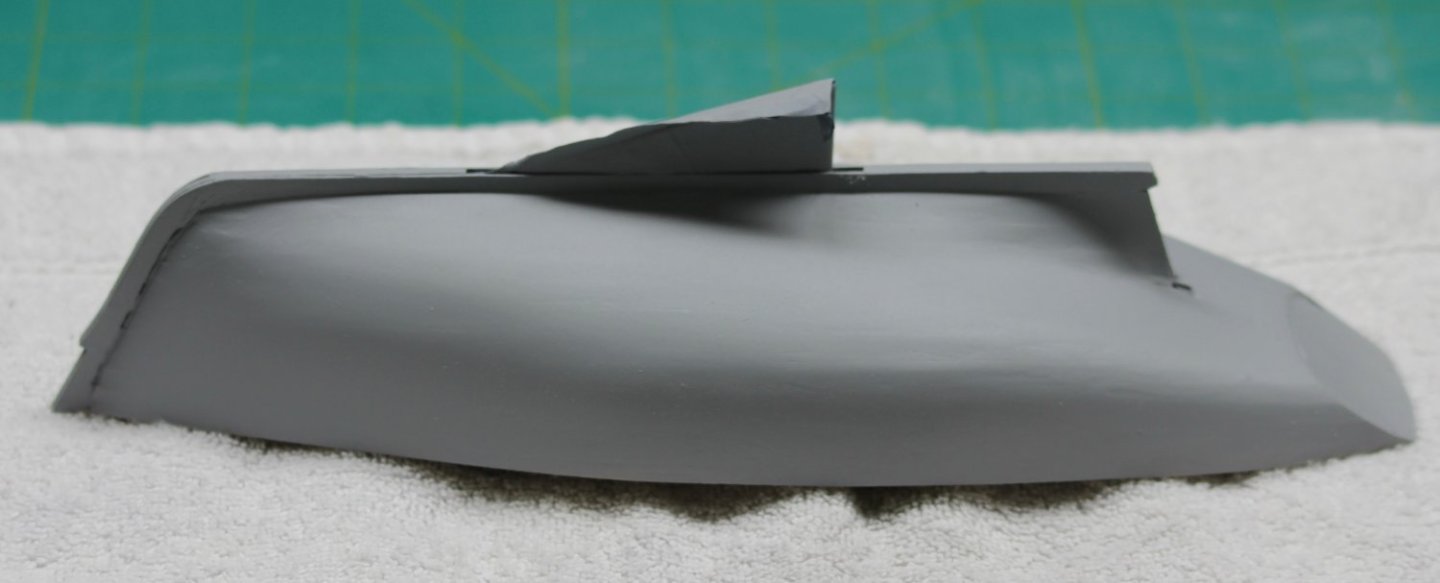
I got the yawl hull planking done and the first set of fill & sand. Here is what it looks like after a brush coat of Badger gray primer. Plenty of work to get done for Fill & Sand #2. After breaking the stem off the pinnance and getting what I hope will be a satisfactory repair I got the first plank on the port side in place and noticed that the transom is a bit too flexible for my liking. This turned out to be a significant problem on the 24' launch as it now has a somewhat deformed stern. To avoid a repeat I installed a "stopper" to keep the transom from flexing (I hope) and (I really hope) will not interfere with the planking operations until the transom is fixed in place by the planking. I used the disk sander to set the angle where the stopper meets the build board in hopes of getting very good contact and then I covered the side of the stopper contacting the transom with scotch tape to keep any glue that might seep up the stopper from gluing it to the transom. I used an adequate" amount of thin CA to glue the stopper to the build board. On to more planking and filling and sanding.


- 422 replies
-
- 5
-
-
- Vanguard Models
- Sphinx
- (and 1 more)
-
The fun never ends. While trying to fit the first two planks on the NEW pinnance I managed to break off the most forward section of the keel. It has a slot in it to presumably engage the first two rows of planks but not on this boat now. So I cut a piece out of the keel carrier sheet, sanded until it just fit and CAed it into place. I am tempted to glue it to the build board too but have not done that yet. Hopefully I will be bit more careful fitting the planks but without the slot it actually may be easier. Trying to get that little plank half way through a 1mm wide slot probably made the task harder than it should be. IMHO it is easier to mate the plank to a solid stem.

- 422 replies
-
- 4
-
-
- Vanguard Models
- Sphinx
- (and 1 more)
-
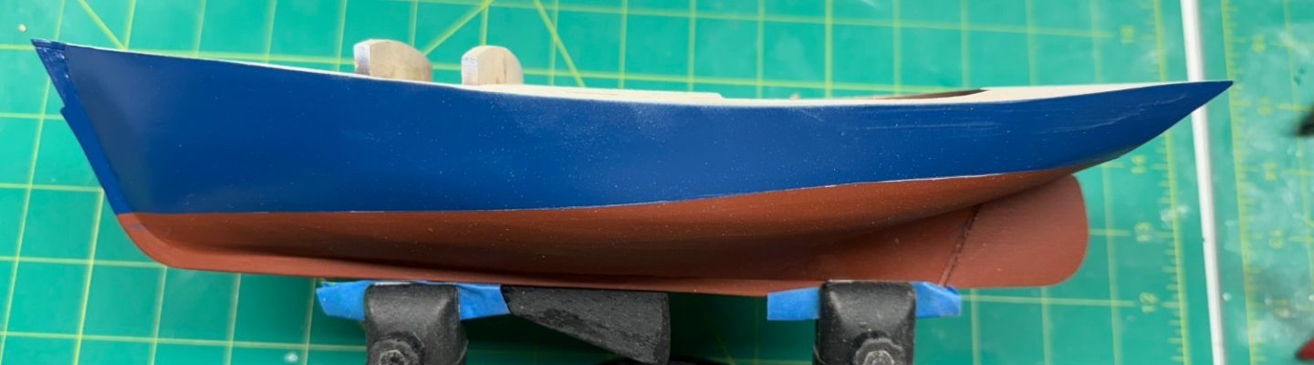
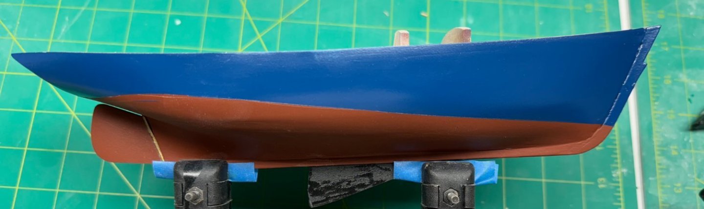
So I painted the entire hull the flat red (spray can of Red Primer from Walmart) then when that was dry I sprayed a coat on clear flat on the lower hull, marked and masked the waterline and sprayed the flat dark blue on the upper hull area. Speaking of the waterline since there is no drawing of the hull I guess you are supposed to use the marker provided with the hull on the display strand to get the waterline. I tried this without much success so I put the hull back in the Amati holder, measured and replicated as best I could the angle produced by the display stand and used my own waterline marker. Looking at the pictures below I am not really sure I got it right but "it is where it is". No particular problems, the Tamiya masking tape kept the blue out of the red. There is one area near the stern on the port side where it looks like it got neither color (still grey). I may add a white tape strip to the waterline to cover this. Not really interested in trying to "fix" this by hand. When I am sure this is completely dry another coat of clear flat and the mask off the entire hull to keep it "clean" as we move forward.
- 88 replies
-
- 5
-
-
- Muscongus Bay Lobster Smack
- Finished
- (and 1 more)
-
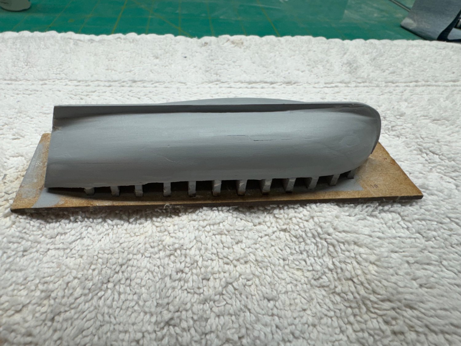
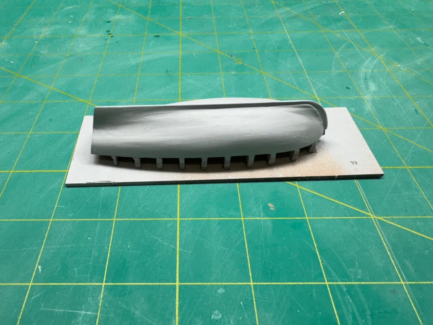
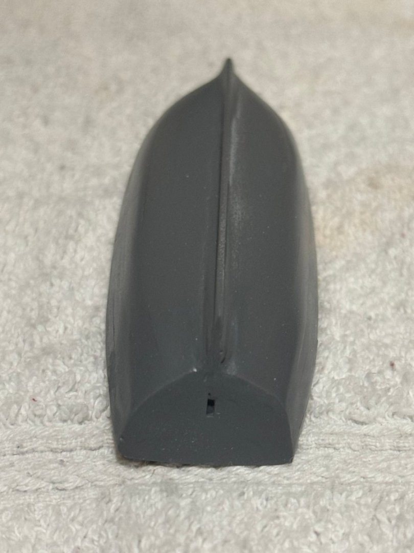
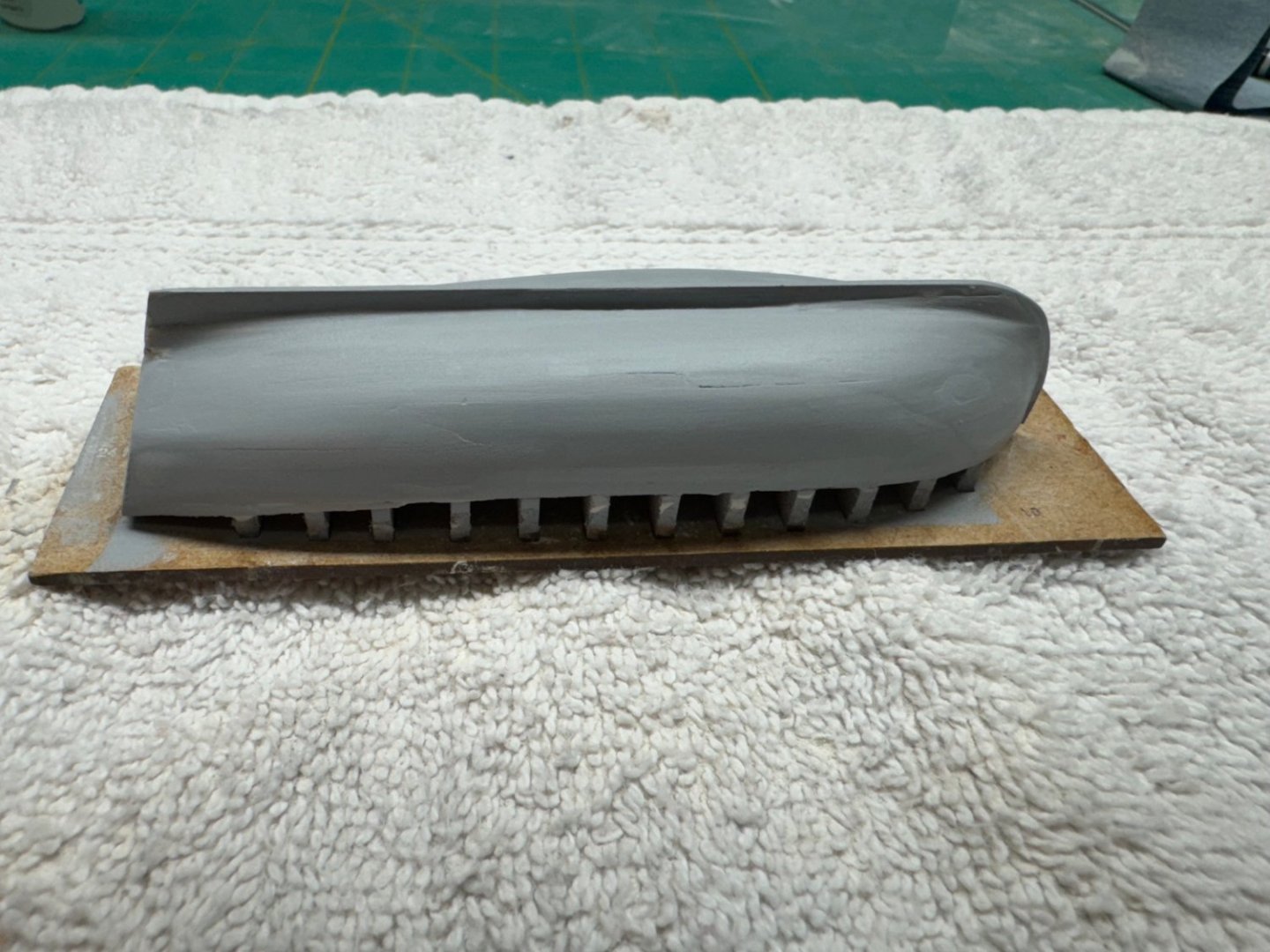
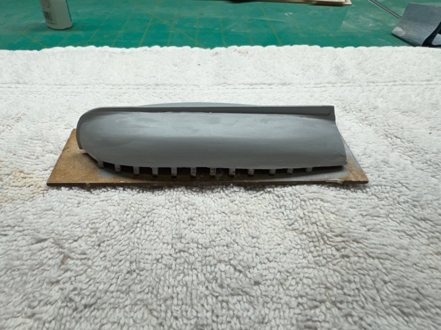
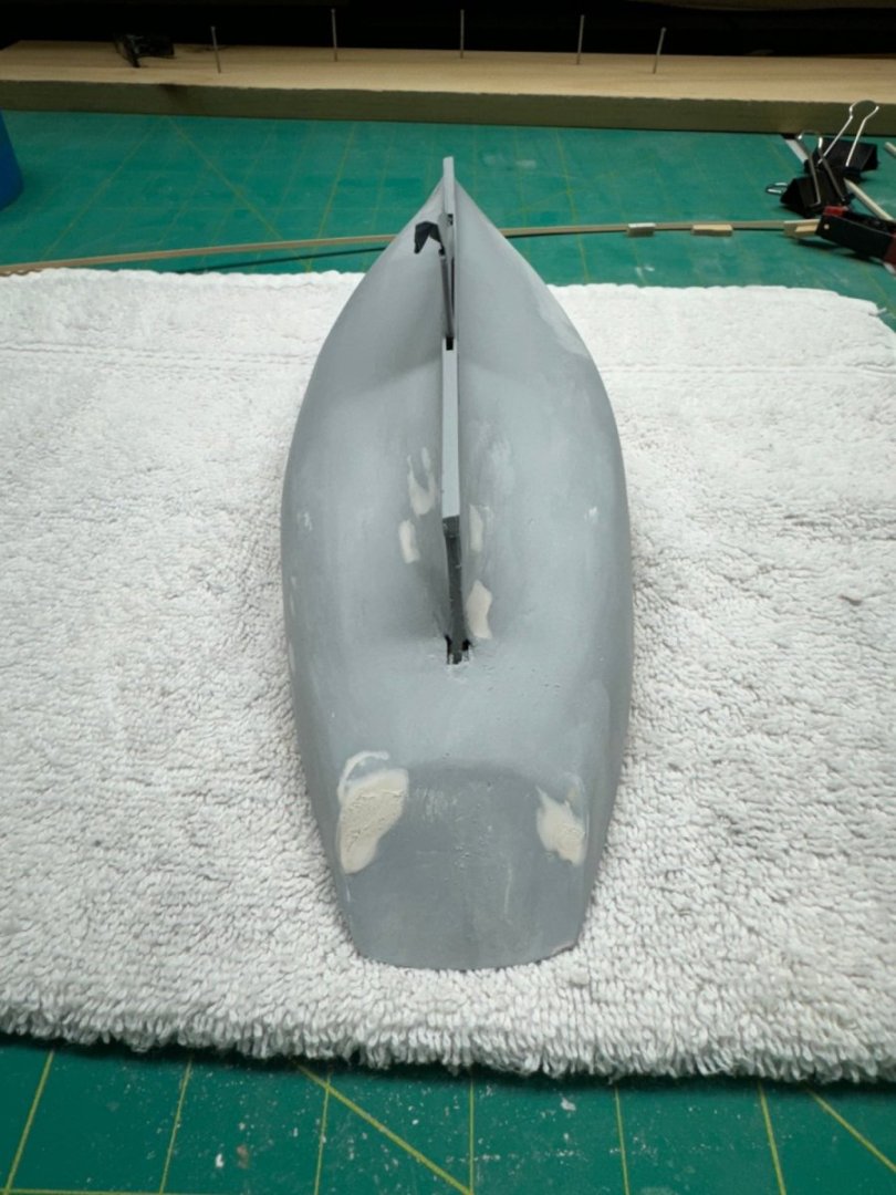
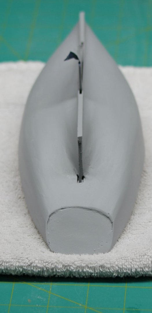
24' launch hull after a coat of grey primer (no filler, just primer). There are a few areas near the keel that could just some additional attention but since they will be "invisible" when on the model I will not worry about them now and press on with the interior details. The plan is to paint the entire hull flat white, the interior MS 4820 H. Cream (I cannot seem to get the interior of the planking "clean" enough to leave it "natural") with the seats and other topside features varnished pear wood, and add a black band of hull planking above the bulwarks per the instructions.

- 422 replies
-
- 5
-
-
- Vanguard Models
- Sphinx
- (and 1 more)
-
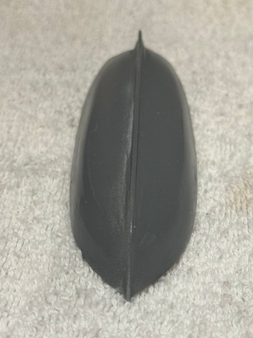
With the launch and yawl hulls more or less (yawl more than launch) it is time to take another try at the pinnance. So here is the hull structure ready for another attempt at a reasonable planking job. I did use thin CA on each of the bulkhead/keel joints. The transom was attached to the P12 with PVA.
- 422 replies
-
- 3
-
-
- Vanguard Models
- Sphinx
- (and 1 more)
-
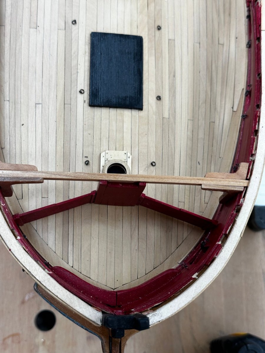
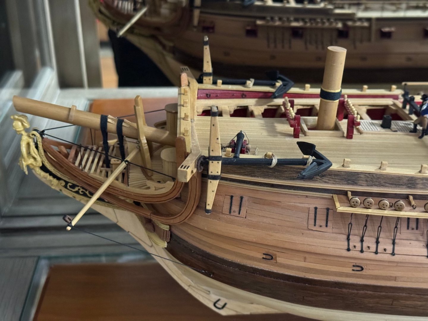
Old Rentner - Thanks but there are other examples of Winchelsea on MSW much better than mine. As to your questions - there is not an intentional gap between the lodging knee (the one running parallel to the beams) and the bulwark - there is a piece of bulwark planking between the outboard end of the knee and the exterior framing. Part of what looks like a gap is the shadow of the bulwark. Here is a picture showing the bulwark sheathing with only one beam and set (one lodging knee - aft of the beam and one hanging knee-forward of the beam) of knees added. You can see the edge of the sheathing extends inboard of the exterior framing. The lodging knee in this case is up against the bulwark sheathing and that was my intent for all of them, although I probably did a better job on some than others. The mark on the hull is the forward edge of an additional layer of planking that is placed there (and shaped the way it is) to add extra protection to the hull while the anchors are being raised (fished is the nautical term). The anchor cables passed into the hull through the one of the two holes (ships typically carried two anchors on each side so that is why two holes) at the left edge of the picture and were raised (or lowered) from the "cat head" which is the wood colored item (with three slots in the upper surface) just above and a little forward of the closed gun port. As the anchor was raised if it moves aft of the cat head (like if the ship is moving forward, even slowly )then it is possible (maybe likely) that while trying to raise the anchor it would impact the ship's side possibly doing damage. Here is a picture showing the anchor stowage position on the USF Confederacy - it is easy (for me at least) to see how getting the anchor up to this position could put some parts of the ship's sides "at risk" of being gouged by the anchor flukes. Hope these answers help and I would be happy to answer any others you may have.

- 389 replies
-
- 2
-
-
- winchelsea
- Syren Ship Model Company
- (and 1 more)
-
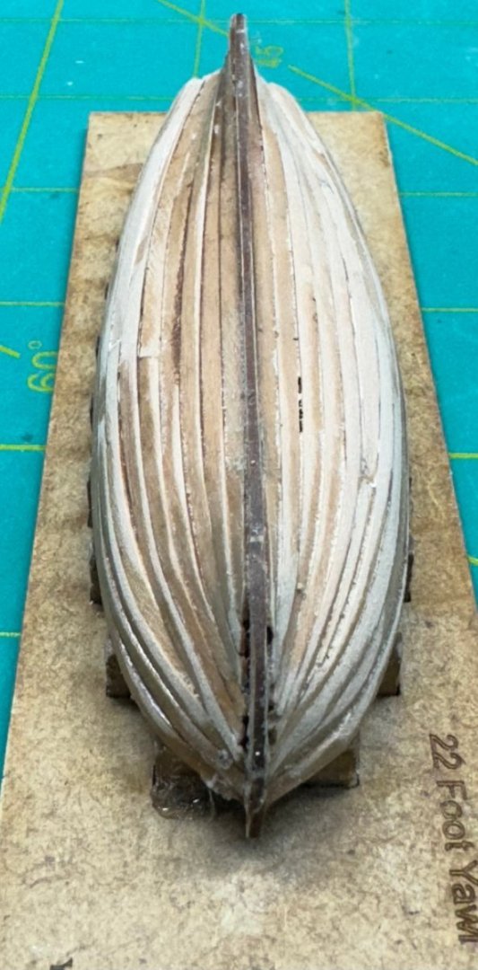
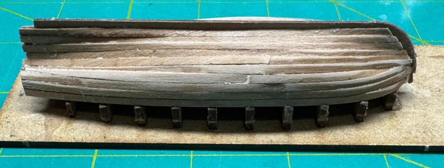
I finished planking the yawl. Here it is after a preliminary sanding before the first fill and sand session. I actually had a drop plank planned out at the bow but the plank broke right where the "notch" was cut so I took that as a bad omen and just made it two planks; well actually three as you can see below about midway between the sheer and garboard strakes. IMHO this was a better job than on the Launch but it will still need a session or two of fill and sand. We will soon see if my gluing the front and back bulkheads to the board will cause problems beyond my having to saw off the "tabs" on each one.

- 422 replies
-
- 3
-
-
- Vanguard Models
- Sphinx
- (and 1 more)
-
Thanks - easy fix, I glued the brass rod with the long part on the wrong side. Should probably have noticed myself or made up some rational like getting all the rudder edges painted- it is REALLY obvious.
- 88 replies
-
- 4
-
-
- Muscongus Bay Lobster Smack
- Finished
- (and 1 more)
-
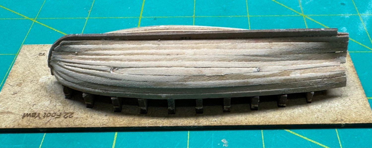
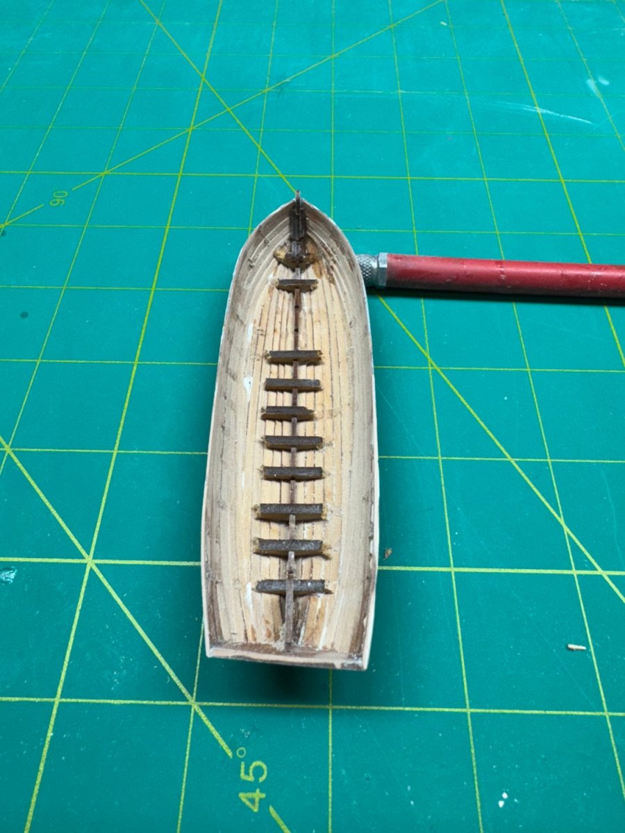
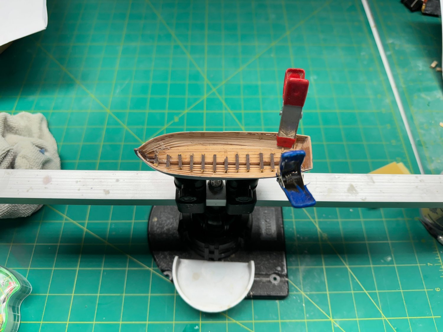
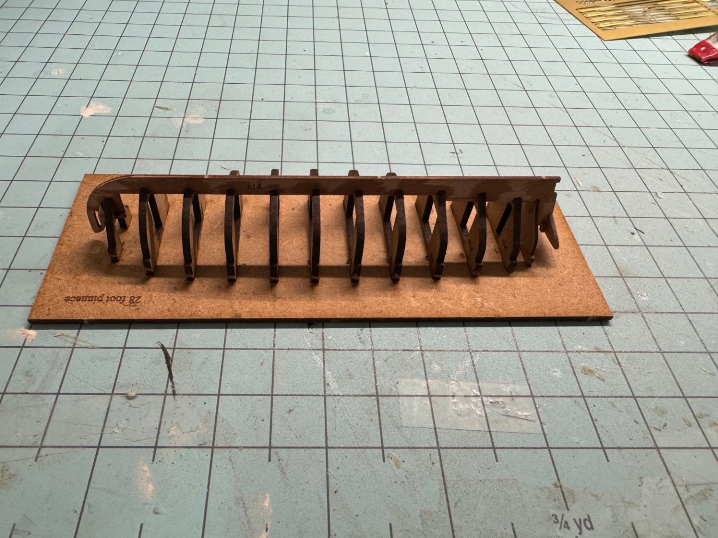
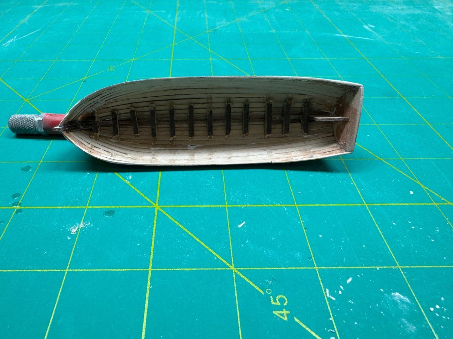
I made one more pass with the filler and primer and then cut the MDF bulkheads out. As you can see in two case the entire bulkhead came out. Probably reinforces my tactic on the yawl of putting a drop of thin CA at each bulkhead/keel intersection. I salvaged the missing pieces and glued them back in. Here you can see that the stern is not completely symmetrical but there is little that can be done about it now. It is very easy (IMHO) to get in this comdition as the transom piece is quite thin and displaces with little effort. And it is harder to see this with the hull upside down. I also noticed here that there is a section of the keel at the very stern that has to be removed now. Maybe I should have done this before (no mention in the instructions) but it came out without drama and I think helped support the keel where the transom attaches. So now on to the ribs. I put the hull in my "keel holder" and can install two at a time. I considered doing a pair at each end but given my obvious lack of planning skills decided this way it will be harder to mess up the spacing.


- 422 replies
-
- 3
-
-
- Vanguard Models
- Sphinx
- (and 1 more)
-
Thanks Reg and Jeff - I have tried most of the commercial brass blackening products over the years and have not found them as effective as paint. I will try the vinegar wash and some flat black spray paint for those items that need to be black - which is most of them.
- 422 replies
-
- 1
-
-
- Vanguard Models
- Sphinx
- (and 1 more)
-
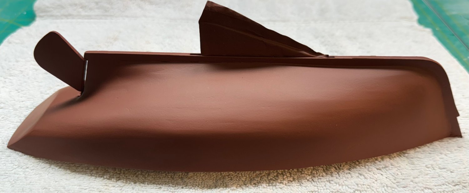
First (and final) coat of hull red. I added the rudder since it will be the same color as below the waterline. Although it is not called out in the instructions I reduced the rudder thickness in a taper towards the stern. I doubt the real rudder was the same thickness along its entire length. I am going to let this "cure" overnight then give it a coat of clear flat before proceeding to mark the waterline in preparation for painting the upper hull.

- 88 replies
-
- 5
-

-
-
- Muscongus Bay Lobster Smack
- Finished
- (and 1 more)
-
This is 24' launch after a dose of filler and primer paint. Not looking too bad especially considering the photos above. Filler can cover..... The 22' yawl is progressing smoothly (relatively speaking) and should have to planking completed in a day or two (maybe three; girl friend's birthday is tomorrow so shipyard time may be very limited).
- 422 replies
-
- 3
-
-
- Vanguard Models
- Sphinx
- (and 1 more)
-
Alan - At this scale there is no physical rabbet. Since the meeting point of the planks at the stem is accomplished by thinning/beveling the planks I find it easier (for me) to accomplish this at least partially after the planks are in place. The lack of taper to keep the planks from ending in points is mostly a lack of planning on my part. As I have said, filler can cover a multitude of planking sins and these boats are all painted rather than "natural" so I think it will work out okay in the end. Thankfully the Sphinx hull is double planked so I will get to practice before planking "for score".
- 422 replies
-
- 2
-
-
- Vanguard Models
- Sphinx
- (and 1 more)
-
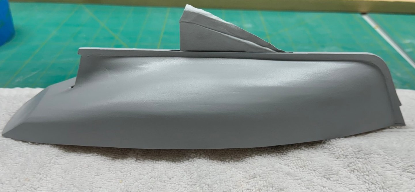
I think I finally got the transom smoothed out. And the rest of the hull looks pretty good as well. I intend to go over the entire hull (lightly) with some 800 grit paper and then put the flat red on (bottom paint) the entire hull. Put a coat of clear flat on the bottom part, mark the waterline, mask and paint the upper hull a flat dark blue. And then several coats of clear flat followed (when dry of course) with the purple delicate surface masking tape to protect the hull moving forward. Which brings up the question of the toe rail. I am going to leave the toe rail off until I get the hull painted. I plan on mimicking the instructions (painted toe rail to look like mahogany) except I am going to use varnished boxwood for the toe rail. It will provide a nice contrast with the dark blue hull. It is also my intent to use varnished boxwood for the rub rail.
- 88 replies
-
- 5
-
-
- Muscongus Bay Lobster Smack
- Finished
- (and 1 more)
-
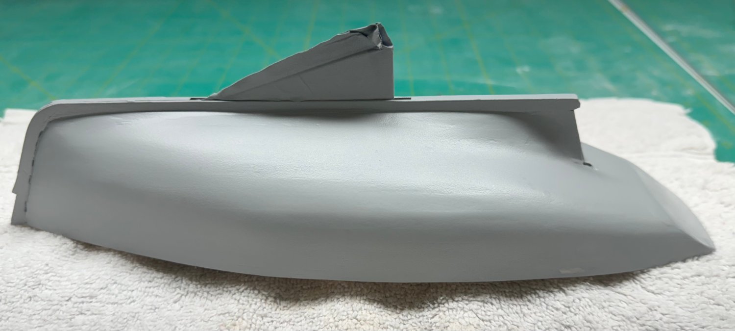
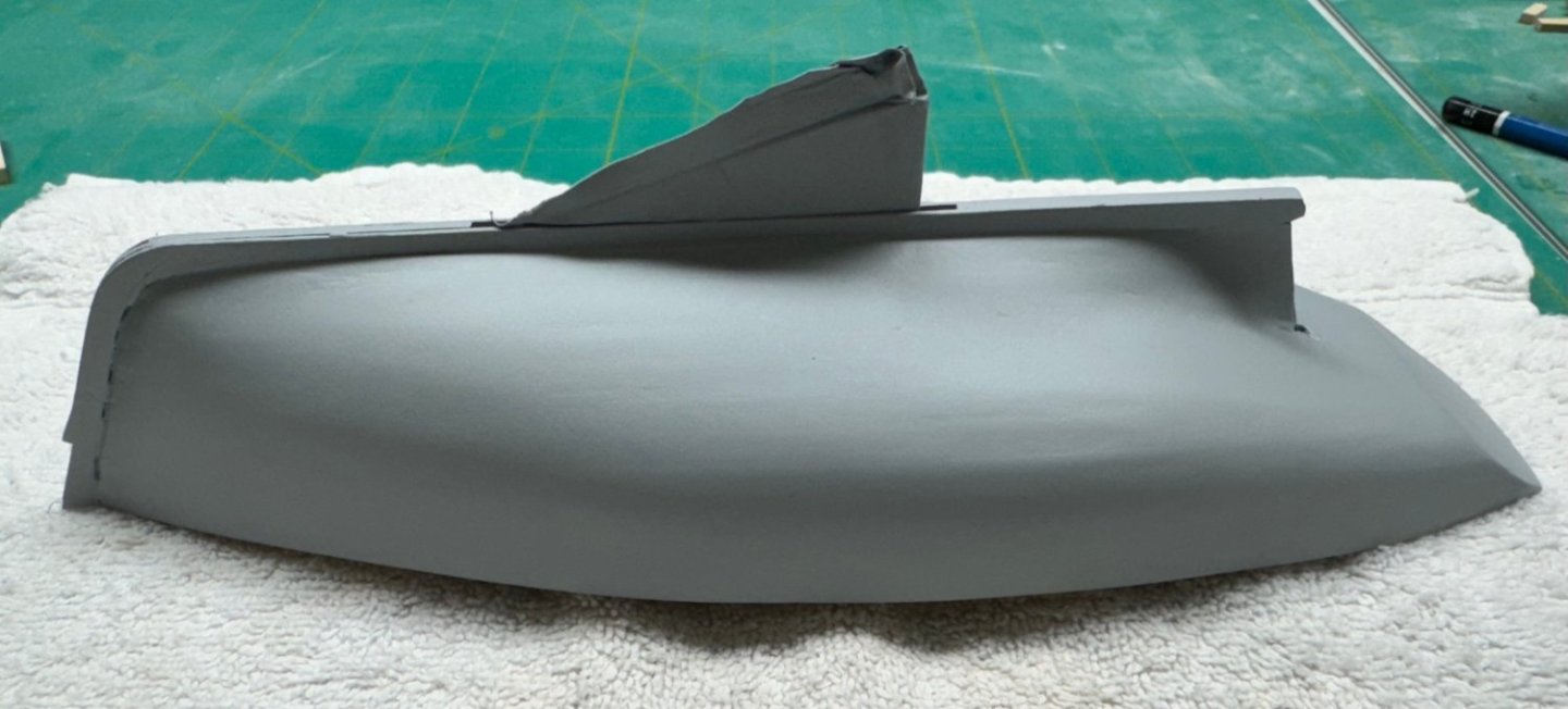
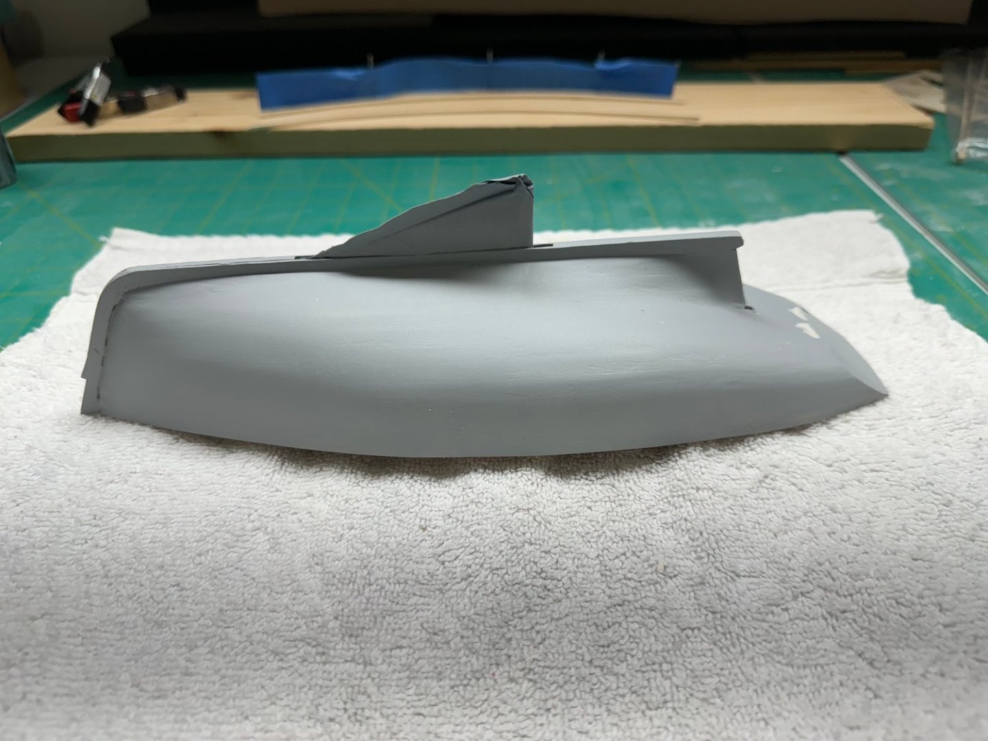
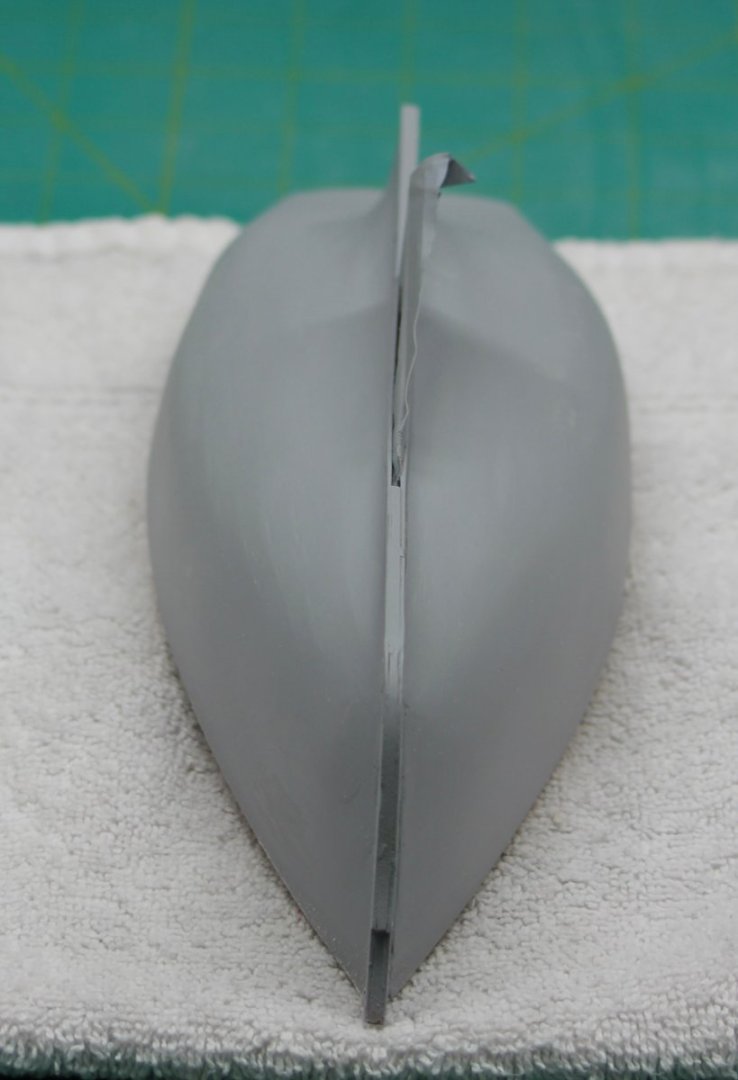
I think I got the transom this time and both sides look pretty good in the photos. Filler is still wet so I need to review again in a few hours after I am sure it is dry.

- 88 replies
-
- 6
-
-
-
- Muscongus Bay Lobster Smack
- Finished
- (and 1 more)
-
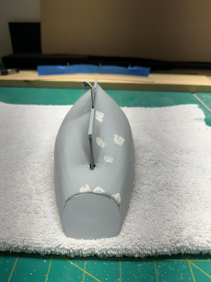
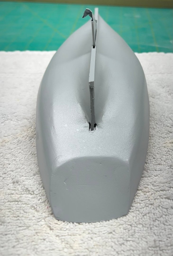
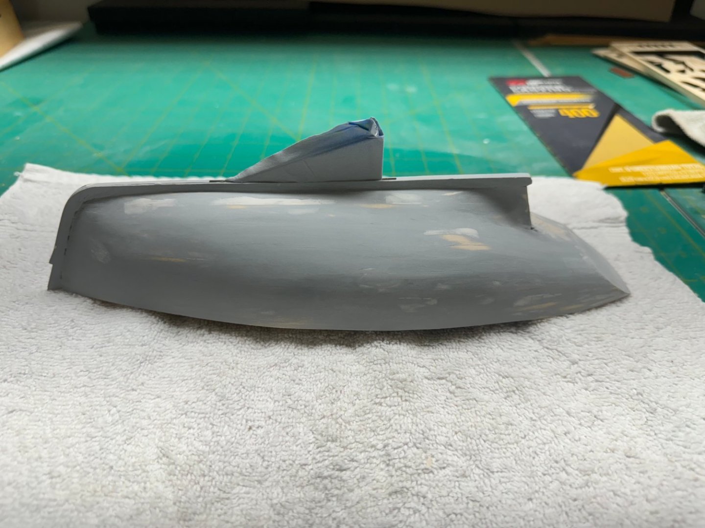
Transom is proving to be more difficult than I had hoped. I think the tapered ends of the hull planking are making getting a smooth finish a challenge. Nothing more filling and sanding can't solve but it may take a few more "rounds".
- 88 replies
-
- 5
-
-
- Muscongus Bay Lobster Smack
- Finished
- (and 1 more)
-
I got one side of the Launch finished - the planking part anyway. After about 7 strakes were complete I gave up any pretense on finishing using stealers and dropped planks. Just too hard (for me) to do that with such small planks. And the pictures in the manual whuch are suoppposed to illustrate where the plank taper was done are next to useless. So I finished off with three rows of planks pointed on both ends. I will finish the other side in a similar manner. Filler/putty can cover a variety of sins.
- 422 replies
-
- 5
-
-
- Vanguard Models
- Sphinx
- (and 1 more)
-
Thanks Eric - my bending jig worked just fine although they were none to generous in length for the toe rail. I think there is less than an .5 inches to spare. What I hope will be the final round of fill and sand. The starboard side looks "okay" while there are a few spots on the port side and at the stern that hopefully some thin filler and 600 grit sandpaper will take care of.

- 88 replies
-
- 5
-
-
- Muscongus Bay Lobster Smack
- Finished
- (and 1 more)
-
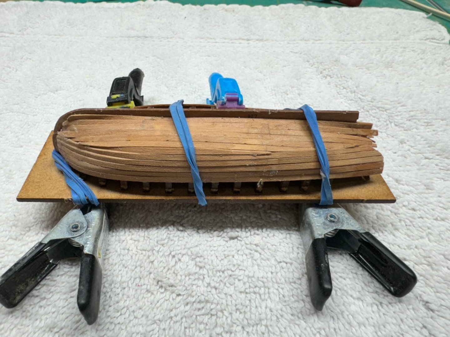
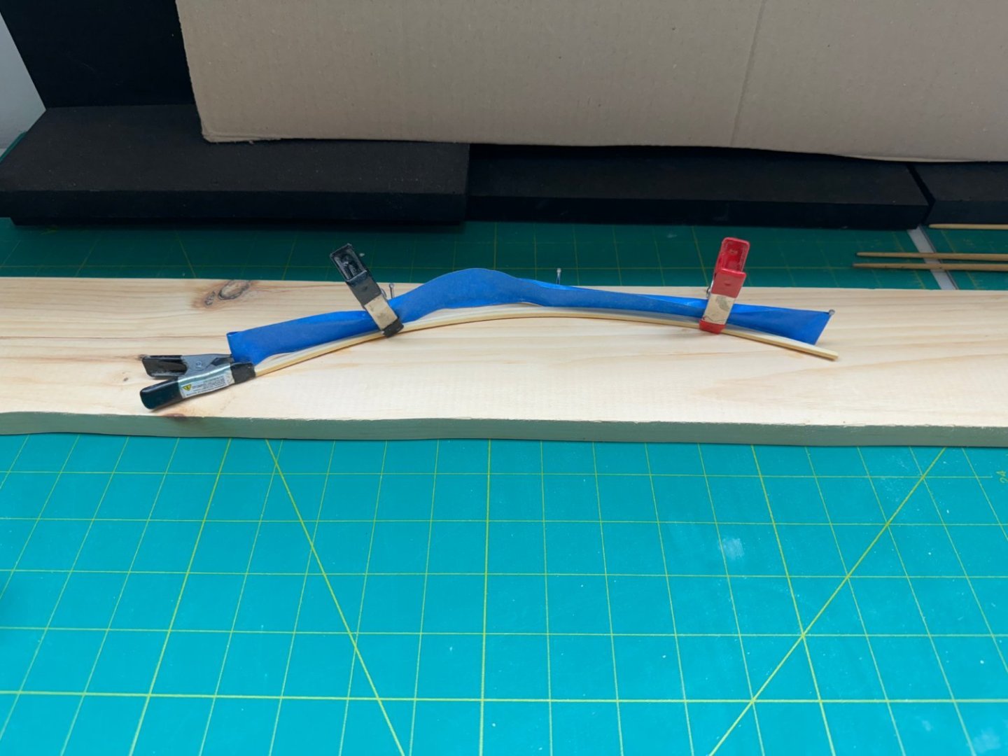
The toe rail will be next whether or not I finish paint the hull now or wait. Instructions say use steam to bend the 3/32" square stock for the toe rail. but I think water alone will work so I laid the hull on a piece of 1 X 4 and traced the deck edge (could have used the deck carrier sheet as well) and then put some nails along the line and clamped the wet stock to the nails. I used the masking tape to make sure the nails do not rust overnight although even if they did the toe rail is painted so maybe the masking tape is overkill.
- 88 replies
-
- 5
-
-
- Muscongus Bay Lobster Smack
- Finished
- (and 1 more)
-
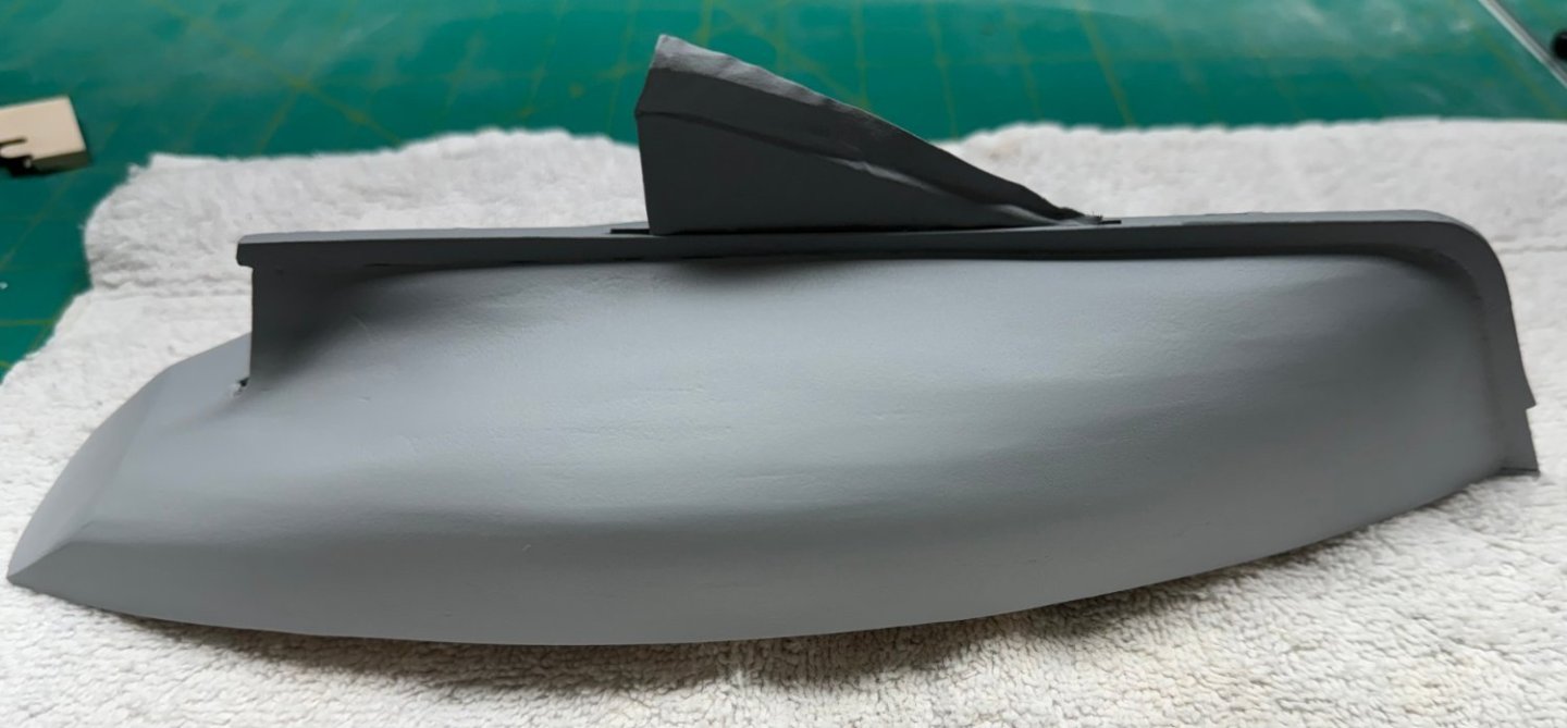
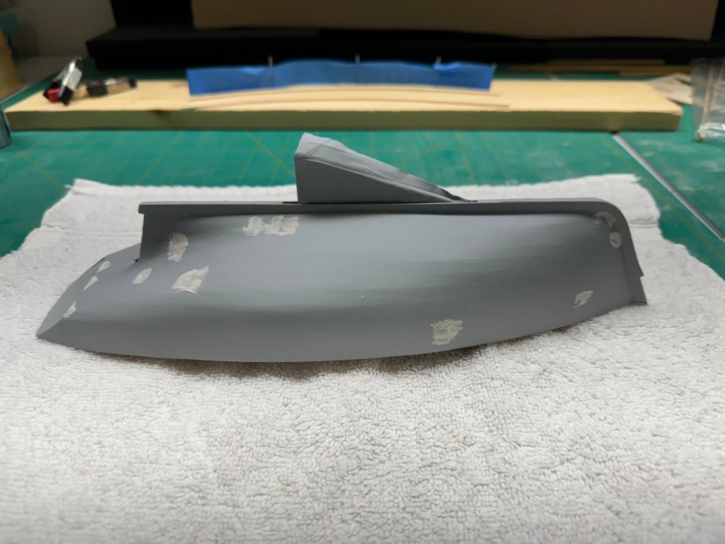
Here is the hull after the second coat of the primer/filler but no sanding (yet). I am considering leaving the transom "as is" because I do not want to "run out of plank" trying to remove all of the "border around the transom. I know there was plenty of plank overhanging the transom but given the very acute angles involved I do not to get to the end of the transom and then have the planking lose its grip and all the filling and sanding would start over again. I will not try and remove the several "edges" that you can see on the sides. Again I do not want to sand through the planking (again) especially where any repairs will be highly visible. I am considering painting the hull now rather than follow the instructions and wait until all of the "other" work on the deck, cabin, etc. is done. My plan is to paint the entire hull a flat red then mark the waterline and paint the upper hull flat dark blue. Then add a couple of coats of clear flat and cover the hull with delicate surface masking tape (the purple stuff). Hopefully this will keep the hull from damage and save a bunch of masking in the future. It also allows the rub rail to be a different color from the hull without having to mask off a 1/16" wide strip along the side. Here are the other sides of the hull as it stands now - one more round of at least sanding then a coat of gray primer (no filler) then the finish coats.
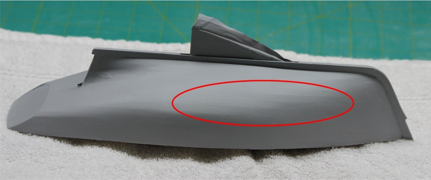
- 88 replies
-
- 4
-
-
- Muscongus Bay Lobster Smack
- Finished
- (and 1 more)
-
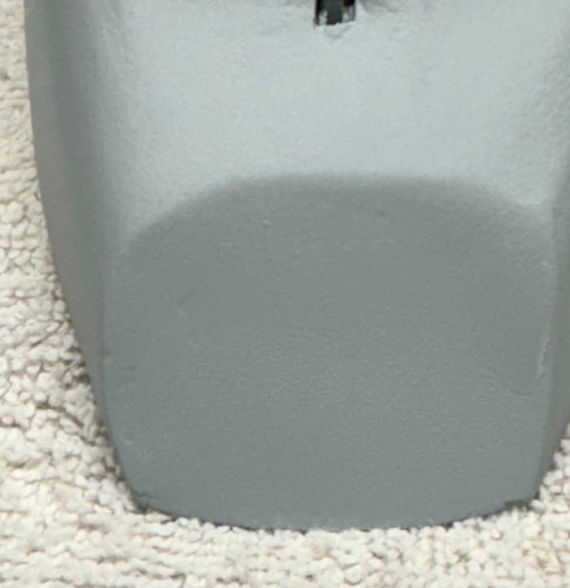
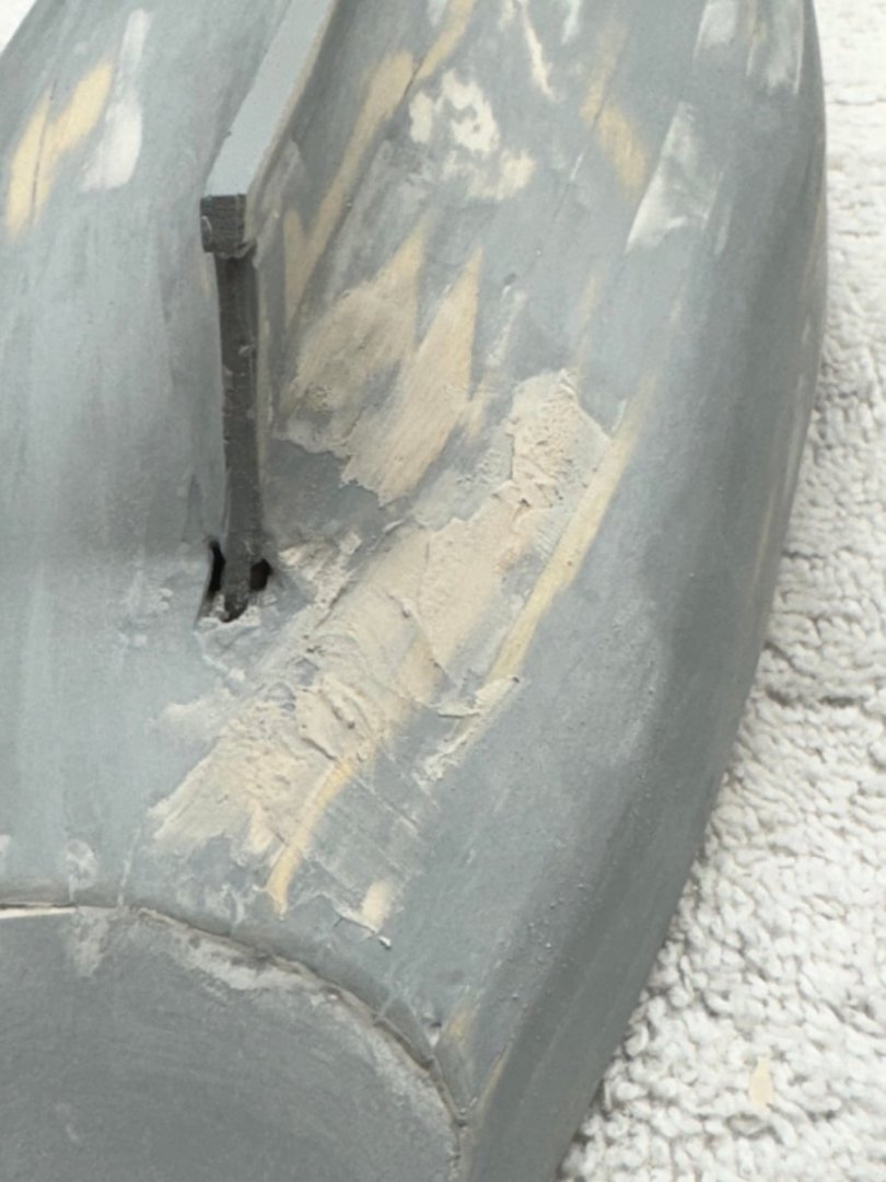
Sanding the problem spots with 400 grit paper. Don't ask me how I know but it really is possible to sand all the way through the planking even with 400 grit paper

- 88 replies
-
- 4
-
-
- Muscongus Bay Lobster Smack
- Finished
- (and 1 more)
-
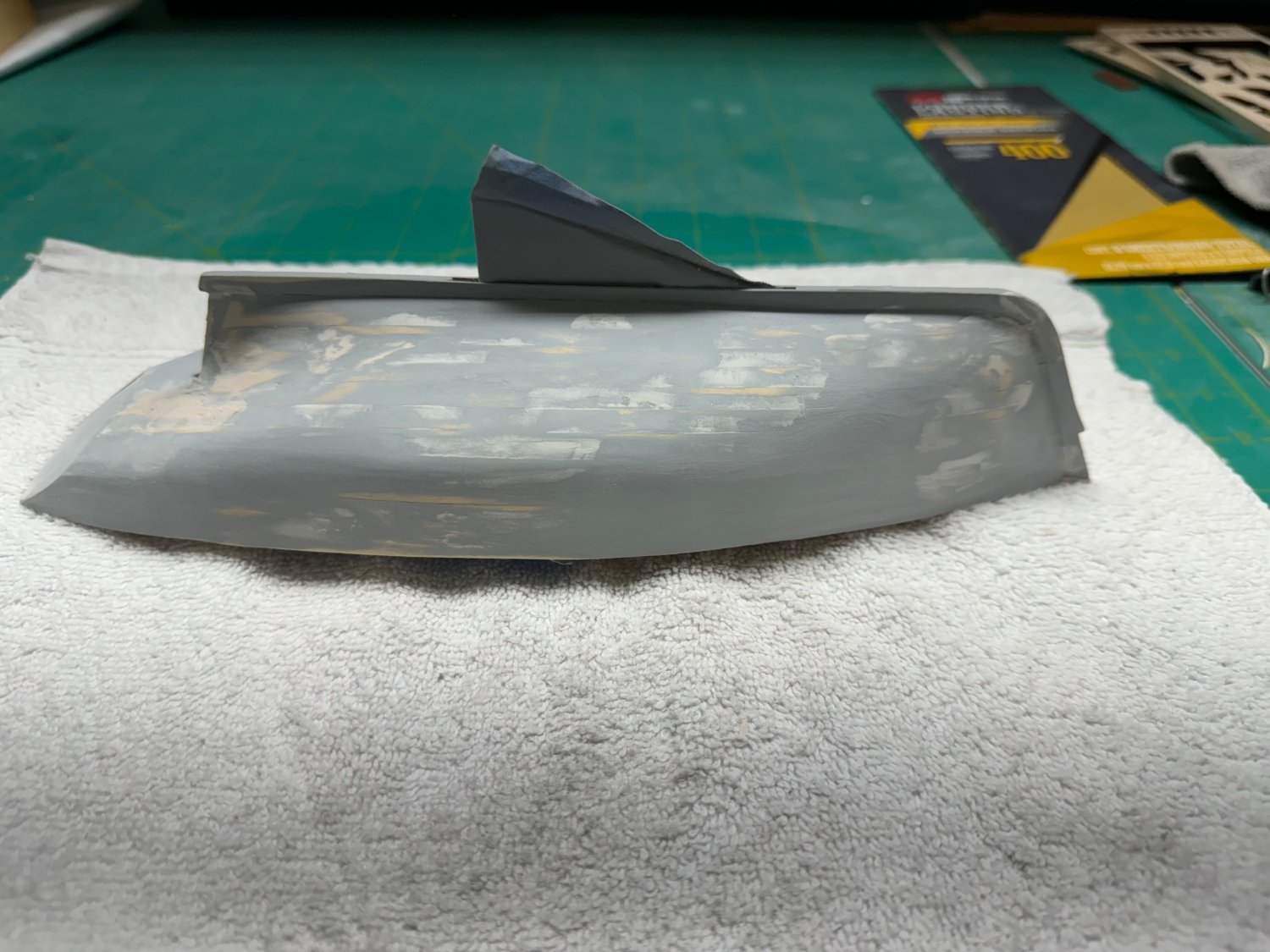
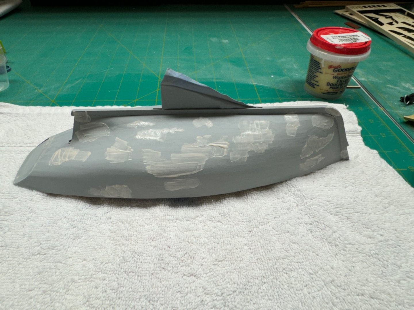
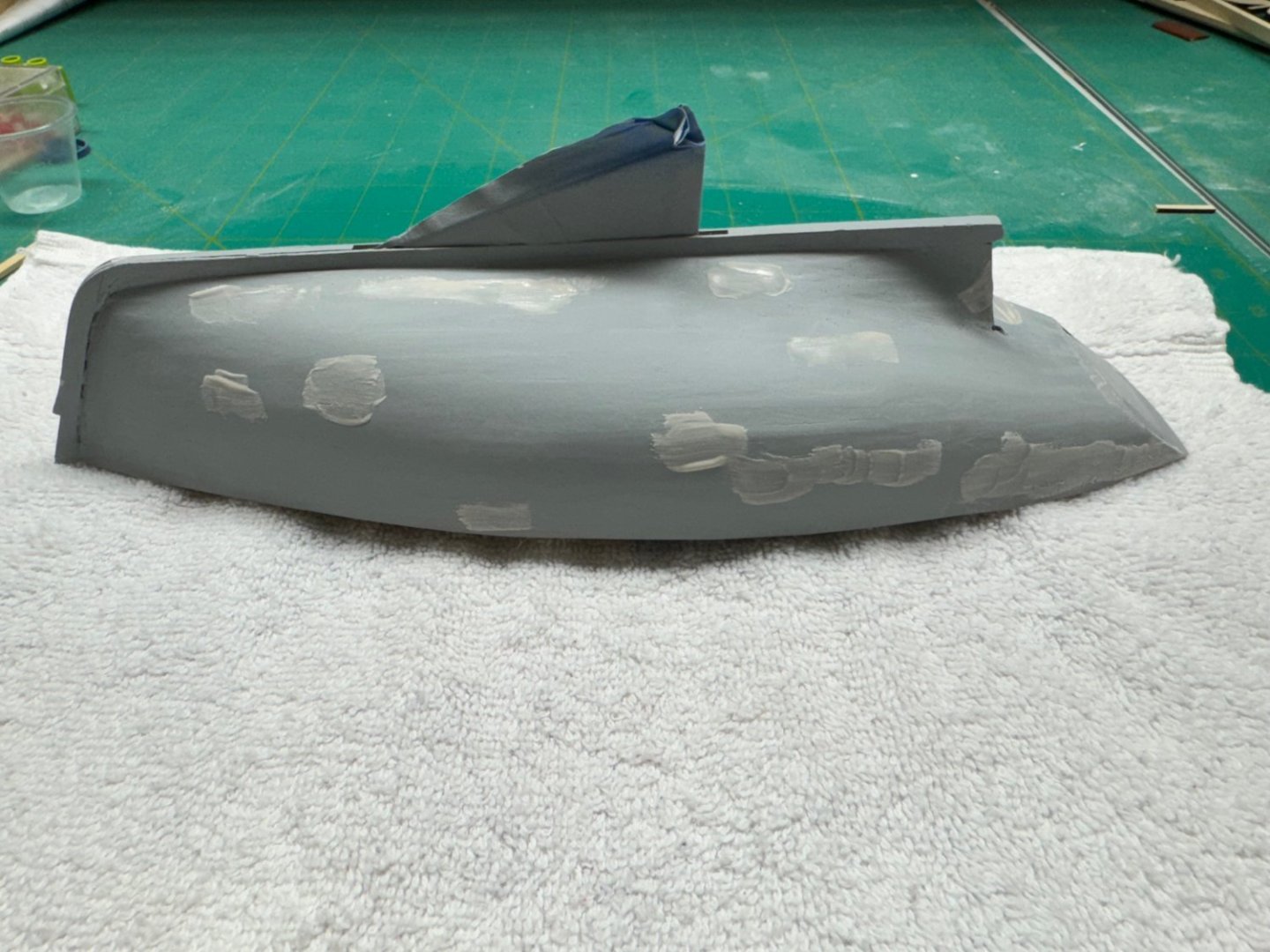
Round 3 of the filler/sand repeat as necessary. This round is 400 grit paper. The next and hopefully last round is 600 grit or maybe 800 depending on how much filler is requiured after this round. The beauty of the filler/primer is it dries in less than an hour so you can get half a dozen runs in a Saturday and still have time for a few odd jobs in between. Hopefully one more pass will do the job here.
- 88 replies
-
- 5
-
-
- Muscongus Bay Lobster Smack
- Finished
- (and 1 more)