cdrusn89
-
Posts
1,923 -
Joined
-
Last visited
Content Type
Profiles
Forums
Gallery
Events
Everything posted by cdrusn89
-
 I started looking at the deck houses and found some inconsistencies on Sheet 3. The overhead view and the side views do not match up dimensionally. The sides are all noticeably (2-4mm) shorter than the overhead. And then I realized the overhead includes the roof overhang. So the drawings are correct as drawn - I should have known.
 -
The quarterdeck was even easier- cut strips to five inches and glue them on. Once dry trim to match transom and forward edge. No issues (at least that I have noticed so far). Here is the completed cherry decking after 220 grit sanding and wiped with paint thinner.

- 166 replies
-
- 3
-

-
- fannie a gorham
- finished
- (and 1 more)
-
Using 1/32 X 3/32 cherry strips from Northeastern Scale Lumber I planked the fore deck. When I got to the outboard area I had to use a 17 Xacto blade (heavy chisel) to square off the junction between the bulwark and deck. Apparently I did not do too good a job the first time around. I used graphite from a carpenters marker (you know the orange ones they sell at Home Depot) to darken one edge of each plank before installation. I tried to pay attention to the junction with the quarterdeck as there is only a 1/32" sheathing on the face to hid any gaps between the deck and the bulkhead. At the bow there is at least the 3/16" waterway to cover up any errors and the bowsprit will cover the center part too. Anyway, there were no surprises in getting the deck planked. I used full length strips every where (no plank butt junctions) as there is quite a bit of the deck hidden under deck furniture and such so that it did not seem worth the effort. I also cut and fitted the waterway for the fore deck. It is just laying in place in the picture. It will be painted white and installed after the deck is sanded and finished (Wipe-on-Poly satin). I put one coat of Wipe-on-Poly on the waterways - hopefully this will keep the wood grain from standing up when it is painted. I am trying to avoid it looking like my cross trees on the Fore Mast. What ever became of the sanding sealer they sold for use on balsa wood airplanes? So here is the sanded foredeck with and without the water ways.

- 166 replies
-
- 2
-
-
- fannie a gorham
- finished
- (and 1 more)
-
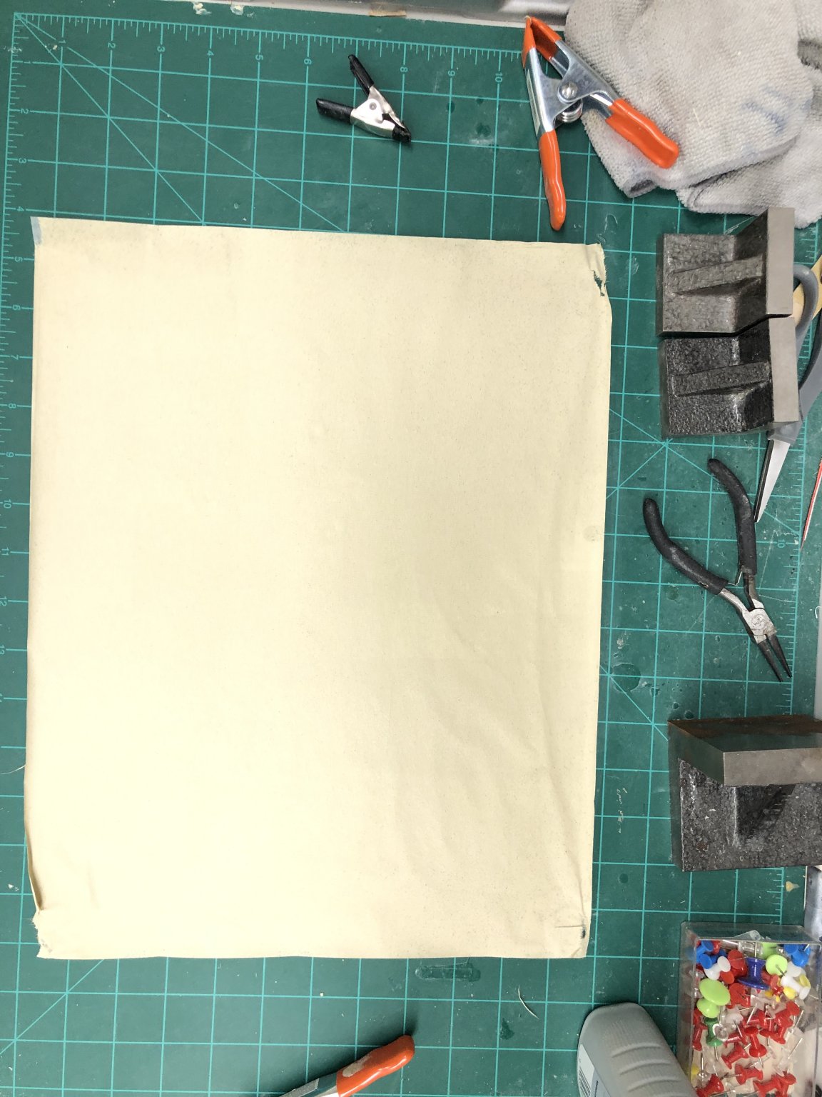
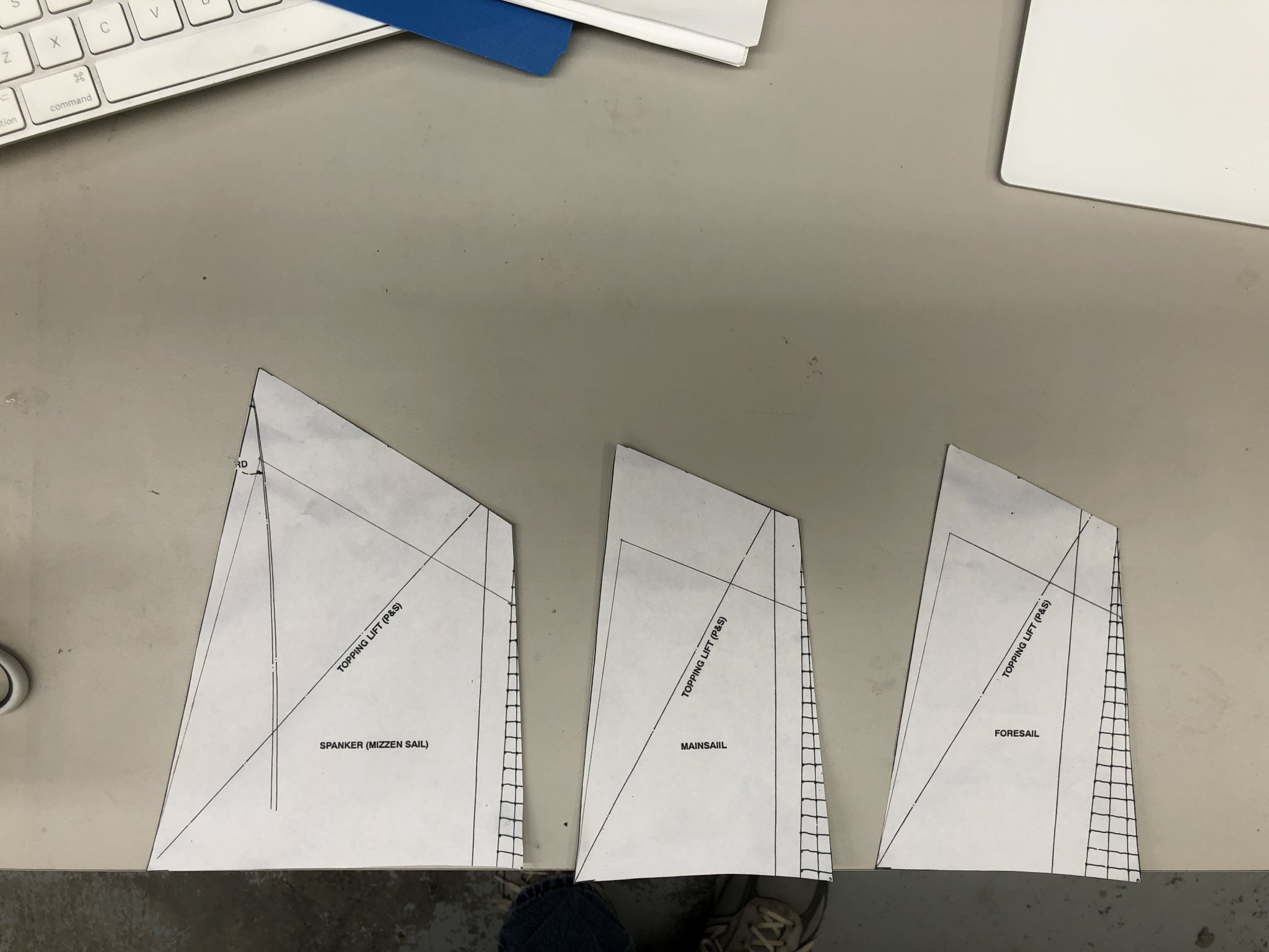
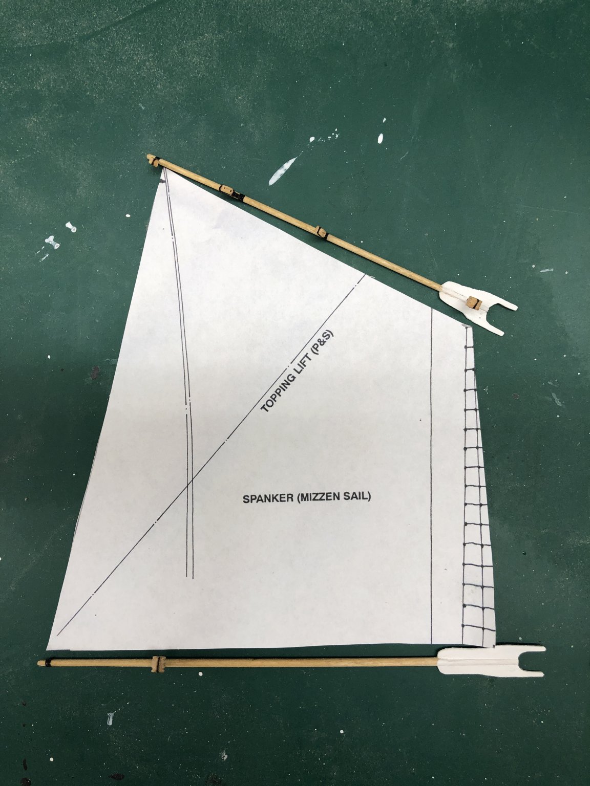
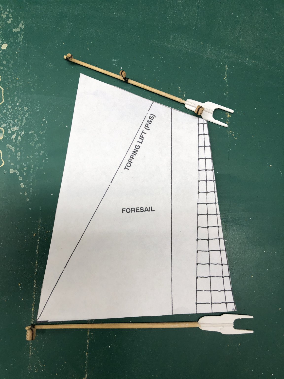
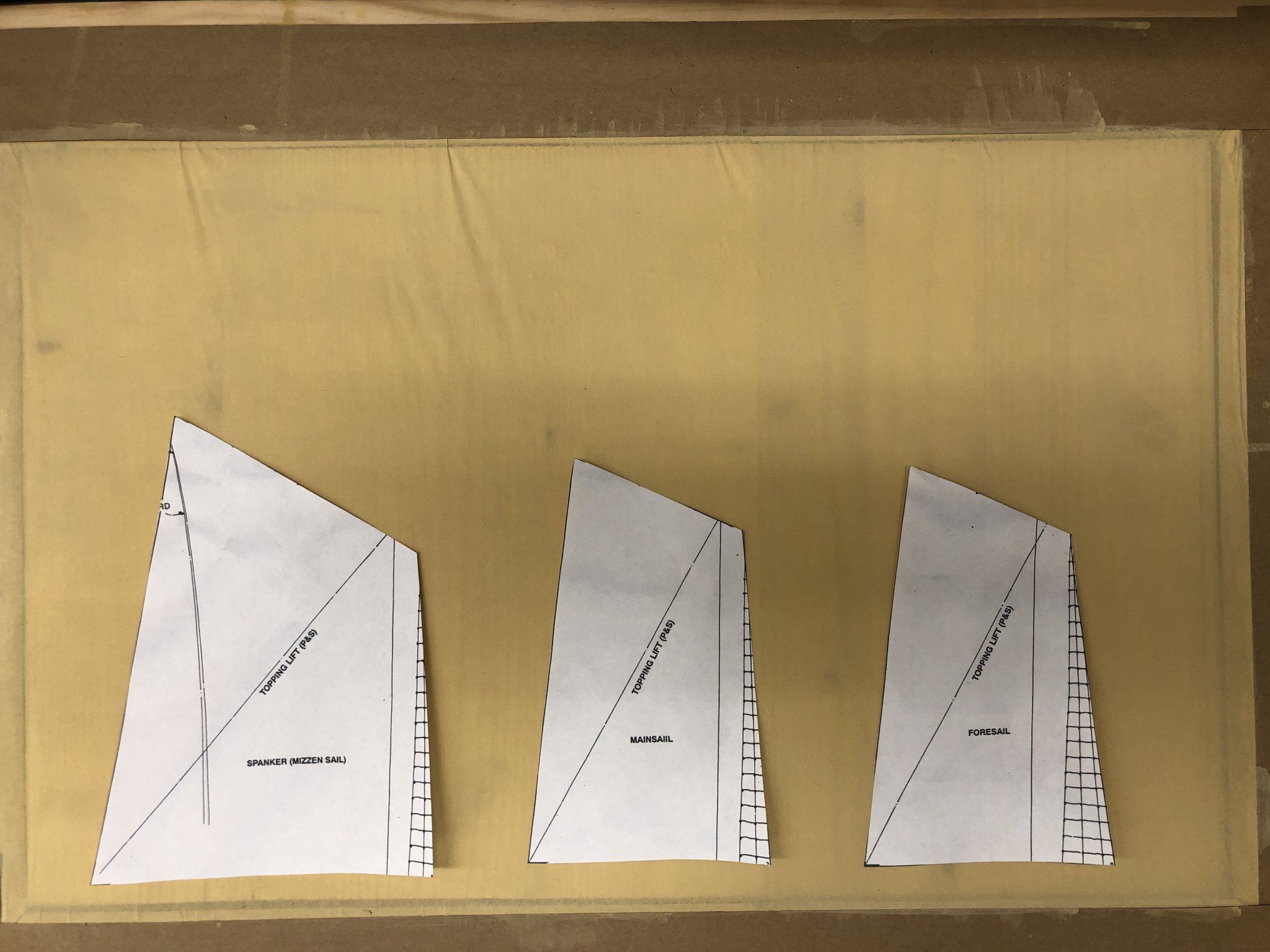
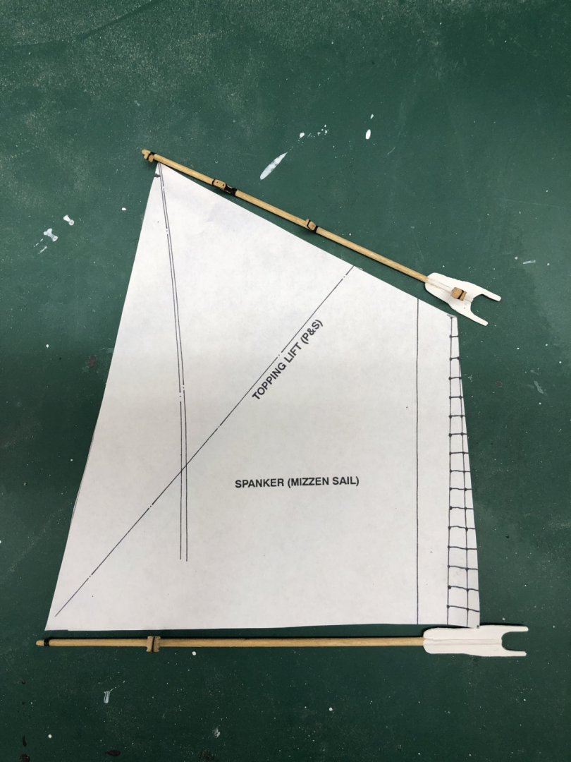
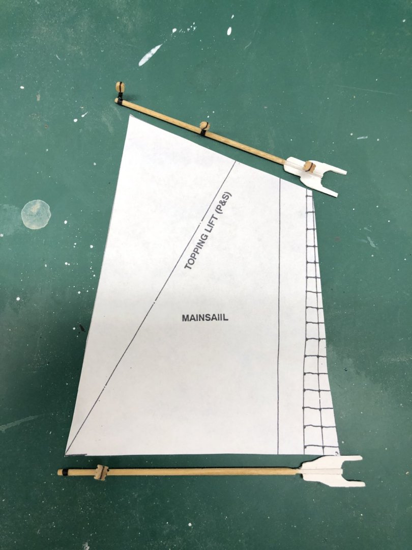
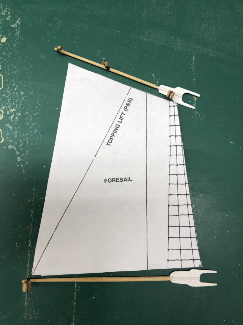
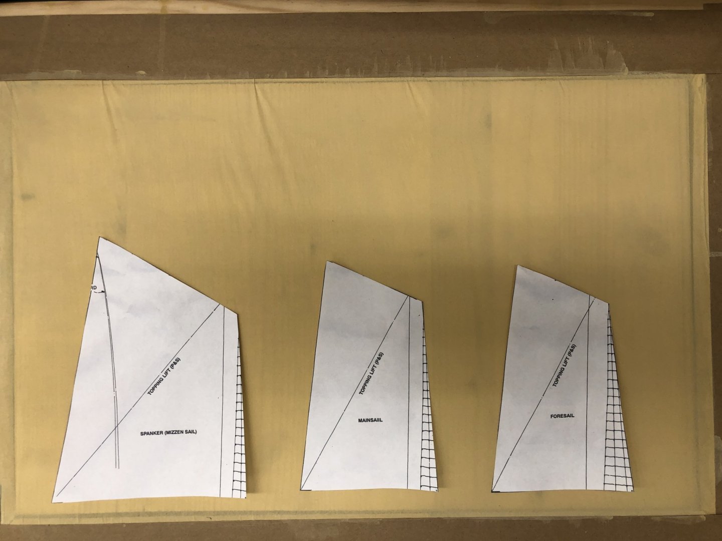
I read somewhere that there is a U-Tube video on making sails from silk span. I watched it last night. My previous experience (based on an Admiralty Models class given in 2014) prepared the silk span by repeatedly applying a very dilute mixture of artists acrylic paint (out of the tube) and water, letting the silk span dry between applications. This takes a considerable period of time (at least for me) as it took 5 - 7 applications to get the silk span almost opaque and an acceptable color. The U-Tube applies the paint full strength using a foam paint roller. It dries in about 4 hours and you have a piece of silk span read to lay out the sail. Much faster and since I plan to have the sails furled the quality of the paint job (although this looks to provide a more even color than my previous method) is not of primary importance. Below is a picture of the first piece of silk span I made using the U-Tube process. Based on my experience with the Latham's sails I decided to reduce the height of the sails to 4" (from 5.25 approx) to reduce the amount of material that has to be furled. I modified the sail plans that I had cut from copies of the drawing to shorten the leech but maintain the length at the head so it will still fit the gaff. I then cut out the new sail outline and laid it out with the appropriate boom and gaff to make sure there would be no issues once it came time to actually mount the sails on the spars. I was somewhat apprehensive about this issue because the sail plan does not explicitly show where the forward edge of the sails are located. The shrouds and mast lines all run together and the offset you would expect between the mast and the sail is not obvious. From the pictures below the mizzen appears to be "okay" (I have to boom to far forward so there should be enough room at the aft end of the boom). The main appears to have a small issue - I need to make the sail a little shorter at them foot. Similarly on the fore. I need to check the dimension on the fore gaff (or the Foresail) - the gaff looks to be too long.


- 166 replies
-
- 4
-
-
- fannie a gorham
- finished
- (and 1 more)
-
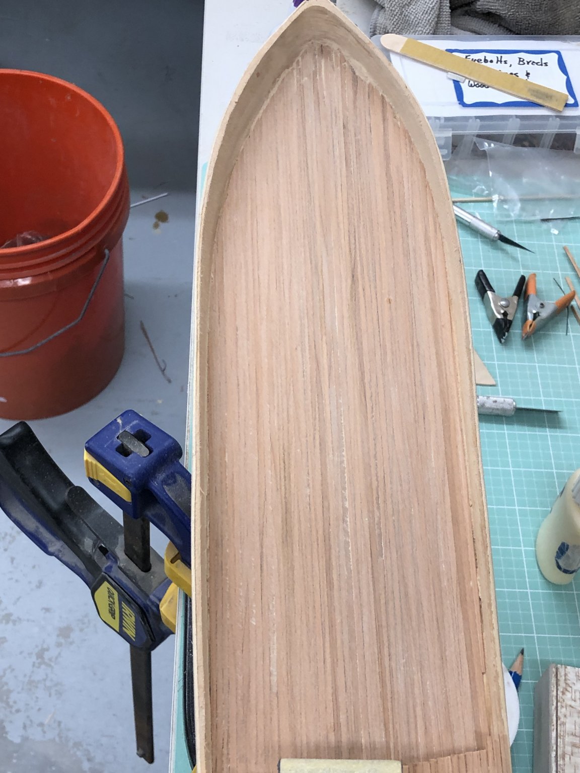
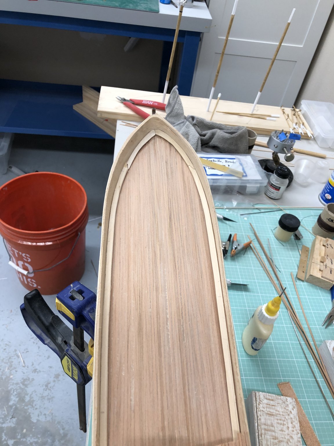
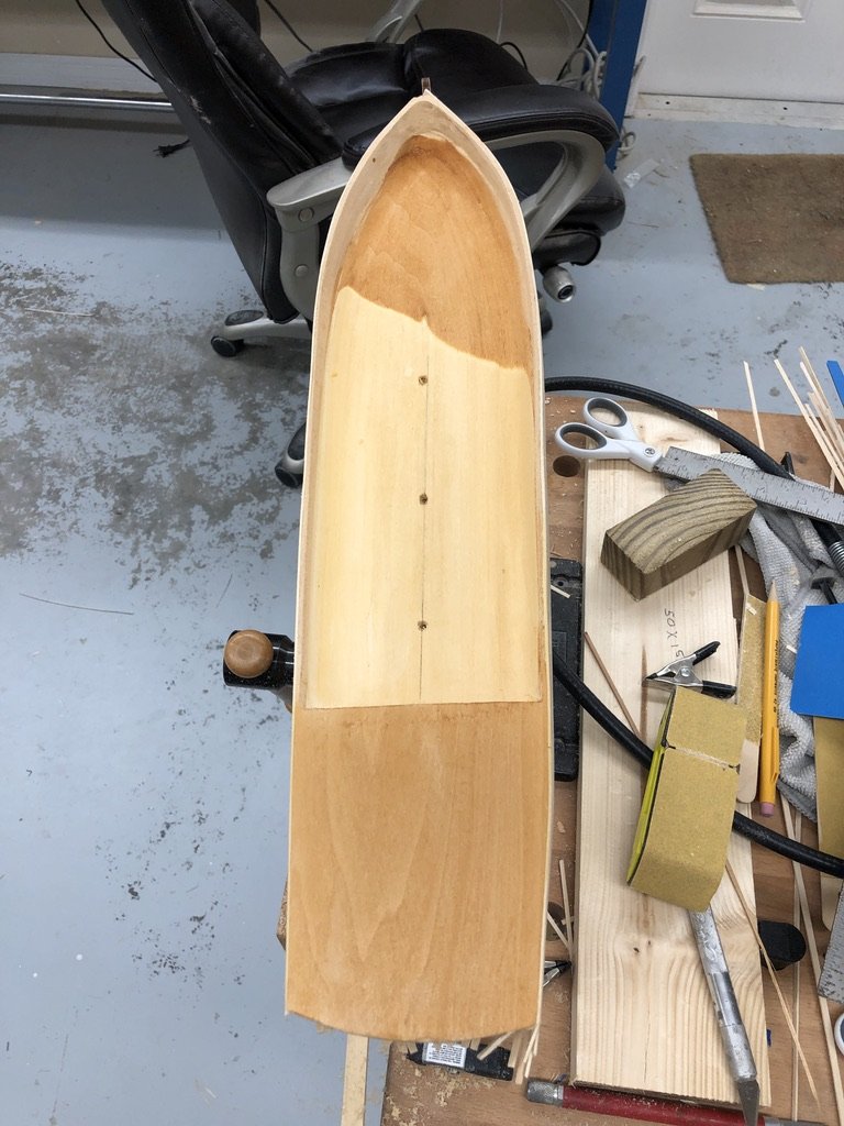
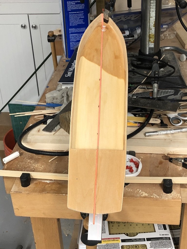
I finished thinning the bulwarks and putting some (but not all) the camber on the deck. The plans only give you the cross section at the forward end of the quarterdeck where you can see how much camber is at that point. I doubt it is that way all the way forward. Anyway I sanded in as much as seemed reasonable and called it a day. I put a coat of Wipe-on-Poly on the hull and got out my laser level. I used the level to get a straight line from the stem to the measured center at the stern and then laid a thin line of wood glue down that line. I am using 1/32" X 3/32" cherry to plank the deck so I used the laser line to get a piece down the center of both decks. Planks that thin will wander all over the place if you do not have some reference. Once these dry I will continue planking the deck. I am still on the fence about whether or not to simulate the caulk between planks. All the previous decks I have done the decking was lighter than this cherry and the caulk showed up pretty well. I am not sure it would be worth the effort here. My previous experience was with using pencil lead on the plank edge to simulate the caulk but that was all on planks at least 1/16" thick. At 1/32 getting enough graphite on the edge to show up may be an issue. So here is the hull with the poly applied and with the centerline deck planks installed.
- 166 replies
-
- 2
-
-
- fannie a gorham
- finished
- (and 1 more)
-
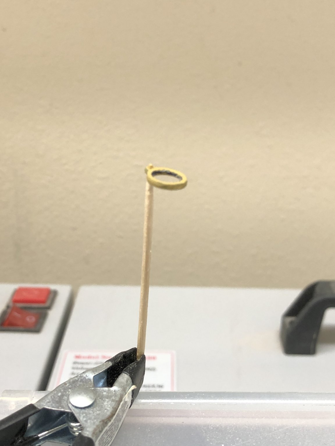
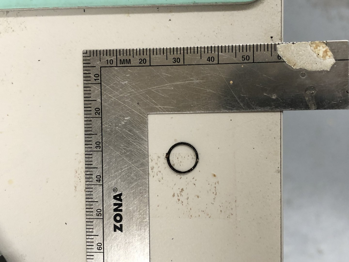
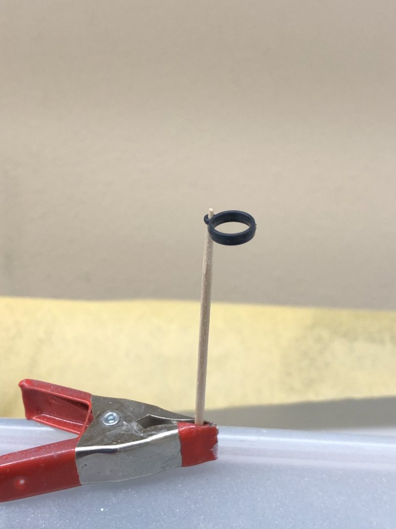
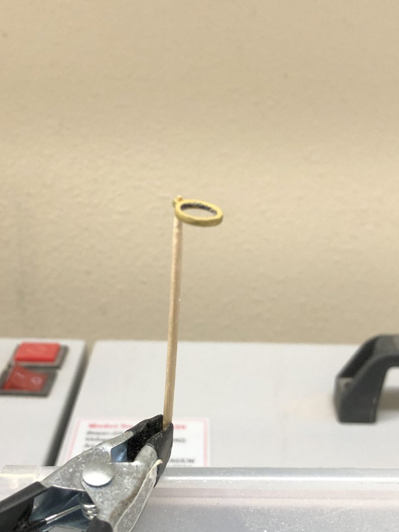
Since I have started getting serious about adding furled sails (and thinning the bulwarks is going soooo slowly) I decided to see about mast hoops. I got an order from BlueJackets of their hoops in 1/4" and 5/32" both of which are 1/32" thick. They may not work out - I broke three of the first four 5/32" ones getting them out of the carrier sheet. They are VERY fragile. I broke the one I successfully got out of the carrier trying to sand off the the area where it connected to the carrier. Assuming I can get 30+ successfully off the carrier and the nubs sanded off I still think they are too fragile to survive being attached to the sail. Here is a picture of the one (second picture actually) I successfully removed before I tried to sand off the "nub". So I looked through my "boxes of parts" and came across plastic mast hoops that are 7mm (inside) diameter which is pretty close to 1/4" (.275 to three decimal places). And it has a ring where the sail would attach. Probably not what the Fannie used but much of the detail of the attachment is covered up by the furled sail. That is the good news - the bad news is the plastic hoops come is a color that is somewhere between blue and gray, close to a Navy blue color and are 3/32" thick. (first picture) So I took one and ran it across a sanding stick a dozen times on each side and painted it a buff color and I think this will work. I order 40 more (just to be on the safe side) from Billings Boats. They have them in brass also but I do not think thinning the brass ones will be as easy as the plastic ones - and the brass ones are not completely closed. (you can probably figure out which picture this is)
- 166 replies
-
- 3
-
-
- fannie a gorham
- finished
- (and 1 more)
-
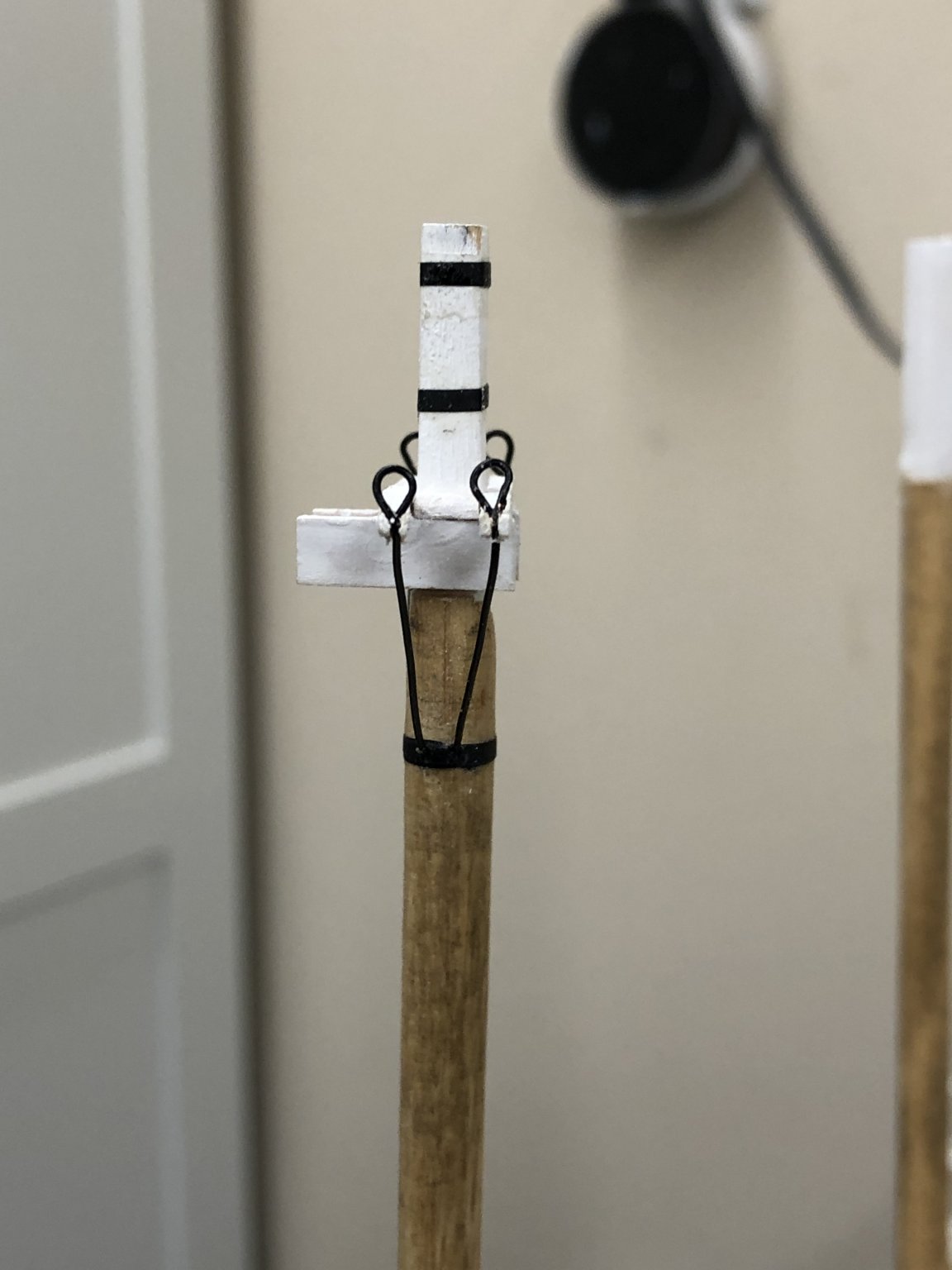
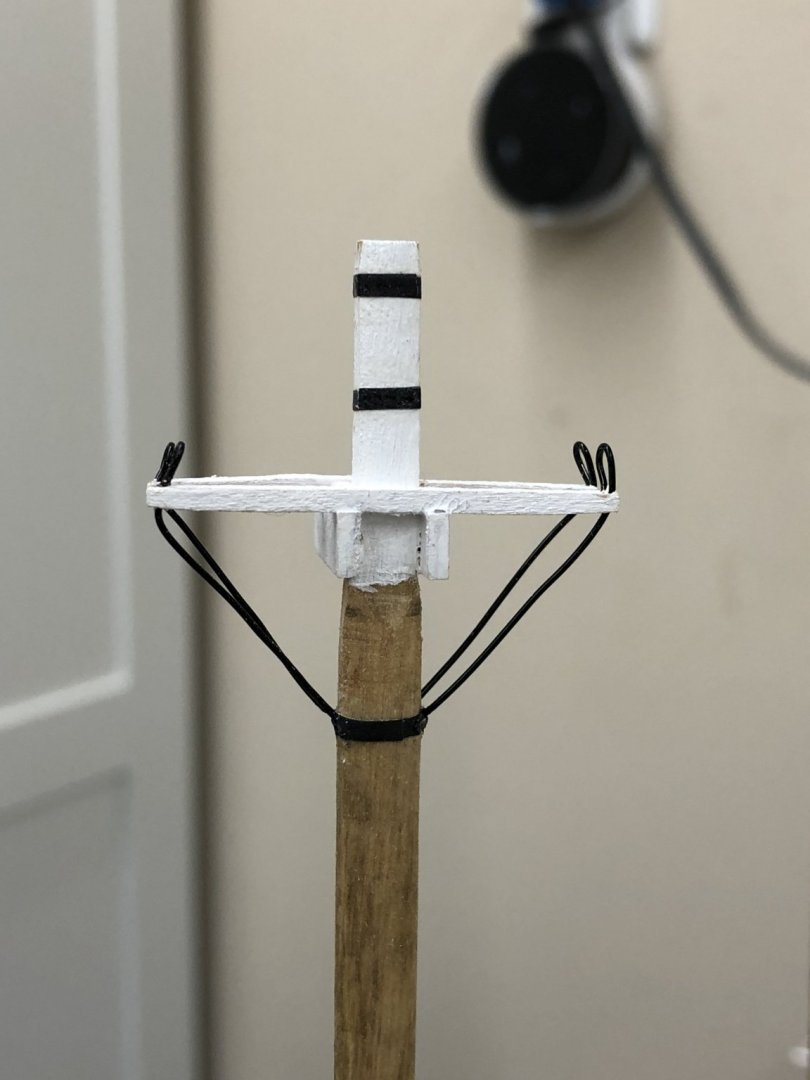
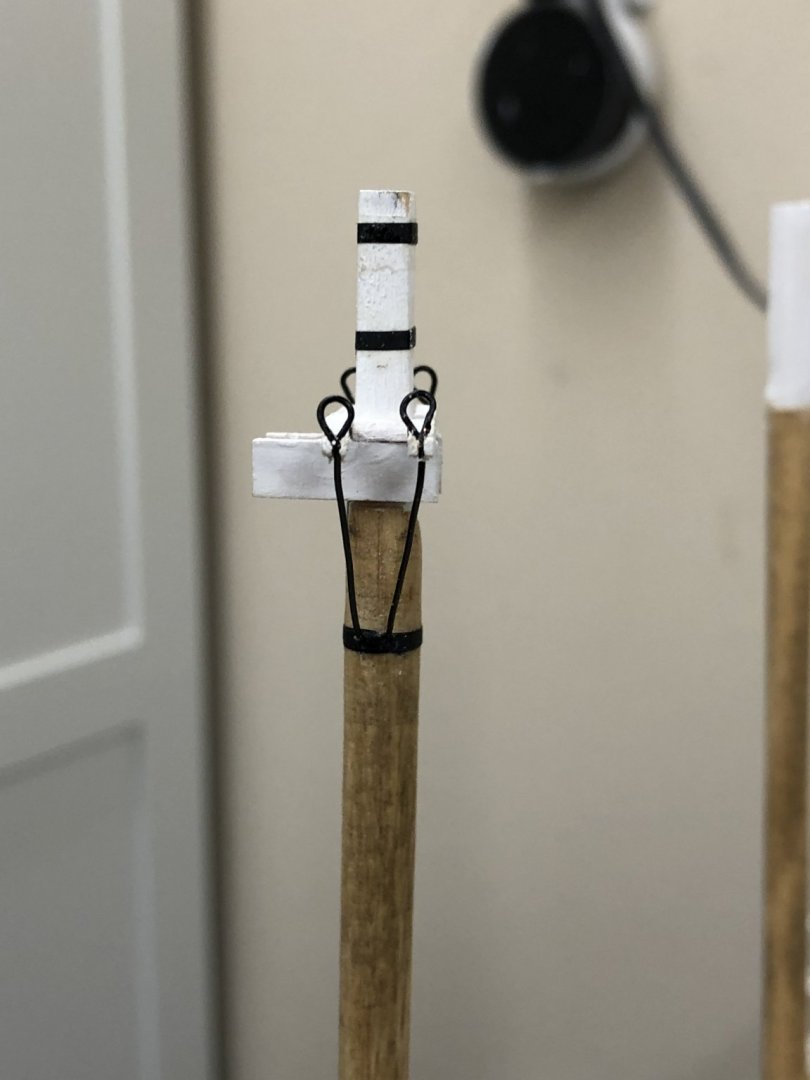
My original plan for the Futtock shrouds was to have eyebolts on the mast with wire leading up through holes in the cross trees with an eye formed in the end of the wire to be the belay point for the top mast shrouds. No plan survives first contact with the enemy as they say. The first problem was getting the correct size wire. I started with 30 gauge (.013") black wire from a craft shop. I was never able to get a really satisfactory eye in the end that went above the cross trees - it was always too long, with the wrapping extending well below the cross trees or the wrappings were too uneven and too long. That and I was unable to figure out a way to attach the wire to the eyebolt in the mast while tensioning the wire straight. Soooo. I pulled the eyebolts out of the mast and used the black striping tape I used on the spars to make a simulated metal band where the eyebolts had been. I switched to 24 gauge (.020") wire and form a simple eye in the upper end. That and instead of a hole in the cross tree, I cut a slot from the outer end to the hole i had already drilled so the wire can slide in. I drilled holes through the striping tape (puncture a hole through the tape with something sharp first - do not try and drill through the tape directly unless you are using a really small (#76 or 78) drill bit; don't ask me how I know. Here is what it looks like now. Wire could be straighter and the eyes look a little on the large side but I think these will do. Now for the other two masts.
- 166 replies
-
- 5
-
-
- fannie a gorham
- finished
- (and 1 more)
-
I seem to recall somewhere a "rule of thumb" of 3 or 4 times the diameter of the deadeye for the space between them. That looks pretty close to me.
- 90 replies
-
- 2
-
-
- finished
- Midwest Products
- (and 1 more)
-
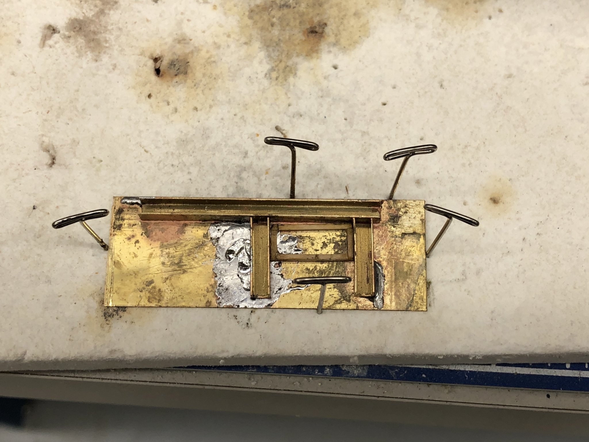
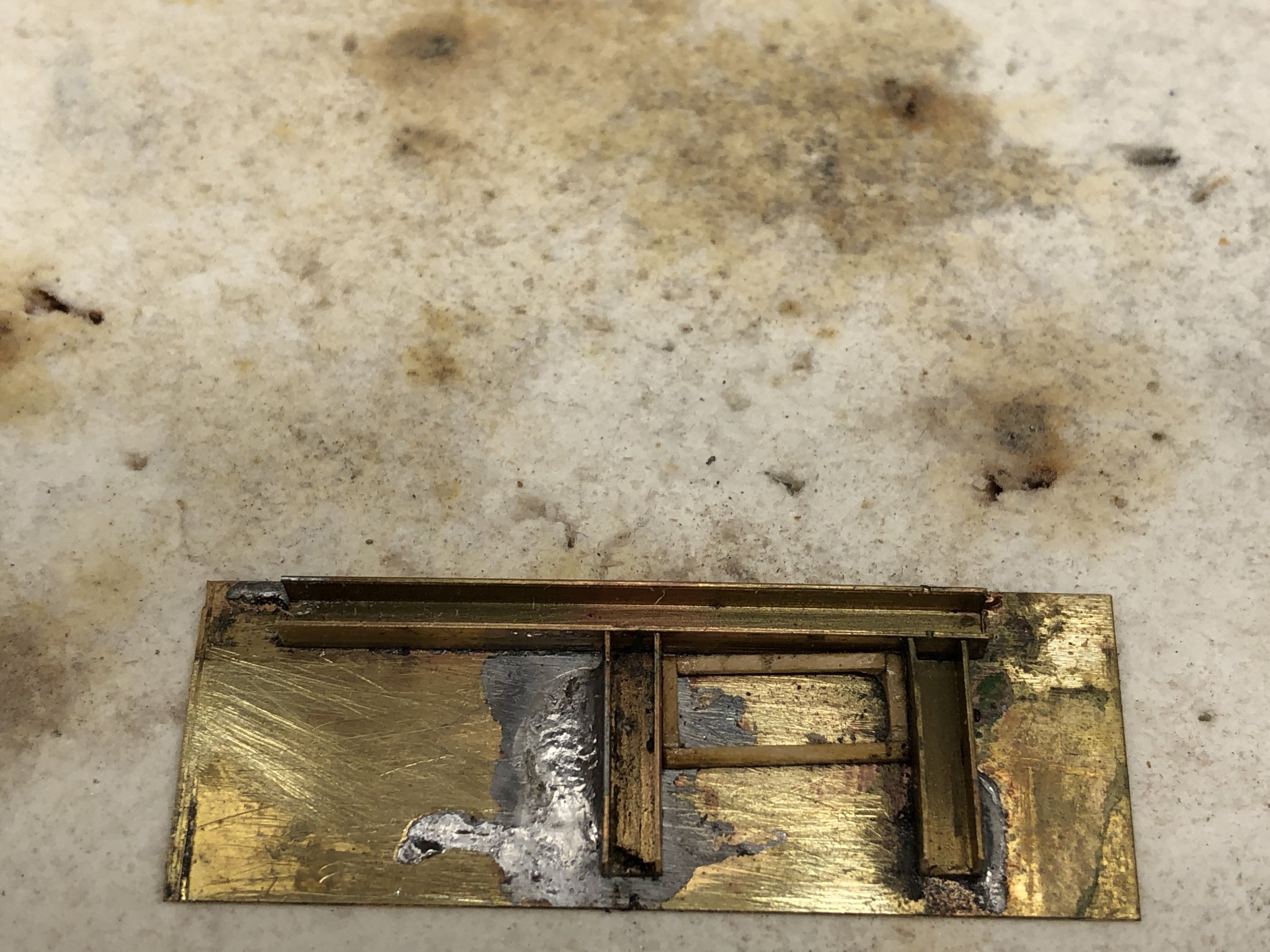
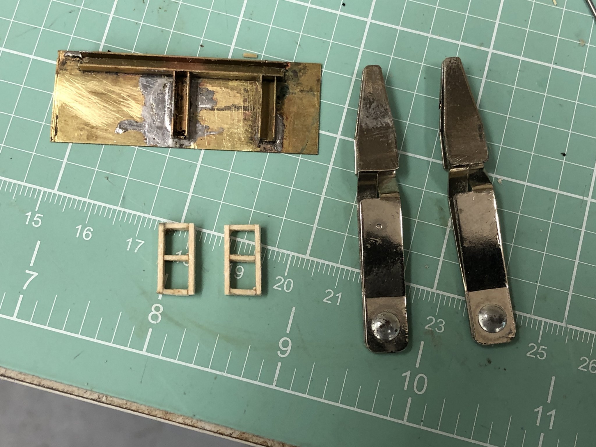
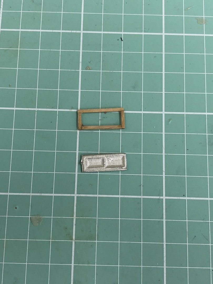
Also while waiting for glue to dry I started looking at the deckhouses. I was not impressed with the kit provided windows as I do not see how (short of cutting the "glass" out and just using the "frame") they could be made "presentable". Someone with a steadier hand and more patience than I could paint the frames white and the "glass" black but I think I can do better. My first attempt at making a window frame is shown below. I used 1/32 X /32 boxwood for the frame and had a devil of a time gluing the joints together. There is just not much contact area for the glue to grab. Since this was the third attempt at a frame and there are eight required I thought I better search for a better solution. I used some scrap brass to solder up a "form" to hold three sides of the frame together. I also decided to use the 3/32 X 1/32 planks from the hull as the sides of the window frame. I did this because I am going to build the deckhouses from 1/32" sheets rather than use the kit provided wooden blocks. I plan to use an additional 1/32" sheet for the siding on the deckhouses. If I mount the window frame flush with the inside of the deckhouse then the 3/32" thick frame will extend outside the siding by 1/32", similar to using the kit provided windows on the solid deckhouse. Here are pictures of the jig assembly and the first two frames.


- 166 replies
-
- 2
-
-
- fannie a gorham
- finished
- (and 1 more)
-
I have also been making preps to at least attempt to fit furled sails (for the fore, mail and mizzen sails only). I used the jig I built to put furled sails on the Latham and the same silk span material. Here is the colored (acrylic paint in a tube diluted with water - five coats applied so far) material with the full size sails. My plan is to cut the sails about 2/3rds of the full height to reduce the amount of material that has to be furled. Since the plans do not show any reinforcing or panel lines I am going to have to do some research (or find my Latham plans) to see how large the panels should be. On the Latham I used 1/16" (or maybe it was 3/32s or 1/8 since the Latham was 1/48 scale) masking tape to simulate the sail seams. That worked okay but I am going to try using colored pencils here first. I have both 3/64 and 1/32 masking tape on hand so I can revert to that if colored pencils does not prove satisfactory. Based on my Latham experience very little of the seams actually shows. There are not mast hoops included with the kit (unusual considering BlueJackets has mast hoops for sale on their site). I ordered enough to put 12 on each mast although I will probably break a few along the way. The BlueJackets hoops are 1/32" thick which would be 3" at scale which seems reasonable but will see how they look on the mast. The sails are just over 5" tall (~ 40' at scale) so a hoop every four feet (10 per mast) does not seem unreasonable. That means a hoop every half inch or so on the model. I have not decided how to attach them yet. On the latham I used .005" line but think I might give white glue a try here. Another thing I had thought of was actually attaching every other hoop since much of that detail is covered up by the sails. Much to ponder.
- 166 replies
-
- 3
-
-
- fannie a gorham
- finished
- (and 1 more)
-
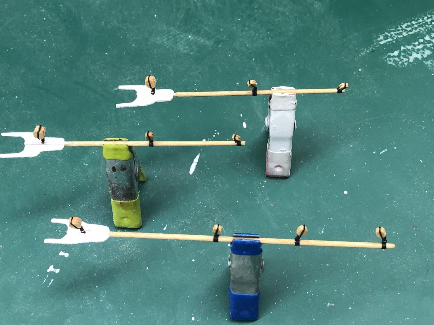
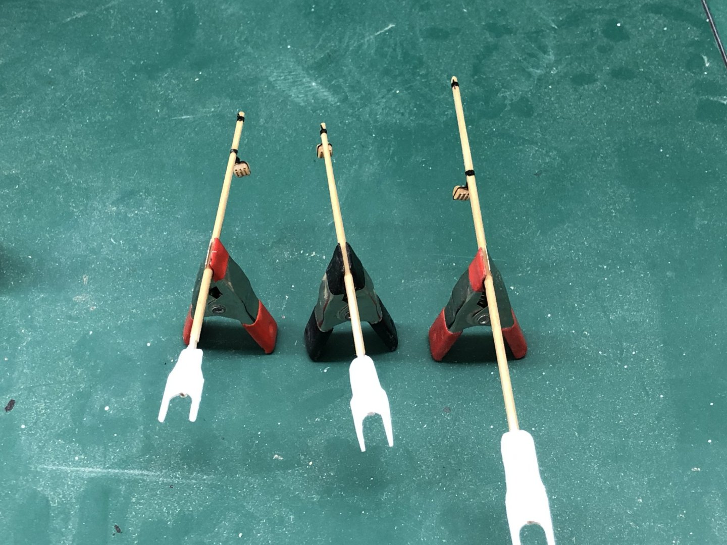
While finishing up the planking I also added the eyebolts and blocks to the gaffs. The instructions say that the blocks on the gaffs should be 3/16" which (IMHO) seems pretty big. Since the instructions provide no (as far as I can tell) guidance on the line size to be used I think 3/16" is pretty big (18" block at scale). I tried using 1/8" (the other size specified in the kit) but that did not look "right" so I compromised and used 5/32" blocks from Syren Ship Model. I will use the same size on the masts as I can see no reason to change sizes. As I understand things, the block size is mostly determined by the line size that will pass through it. The heavier the line the bigger the block since the bend radius of the line is a function of line size and the bend radius required is defined by the size of the block. Trying to bend a thick line around a too small block leads to all kinds of problems. So here are the three gaffs ready for mounting, except for the parrels.
- 166 replies
-
- 2
-
-
- fannie a gorham
- finished
- (and 1 more)
-
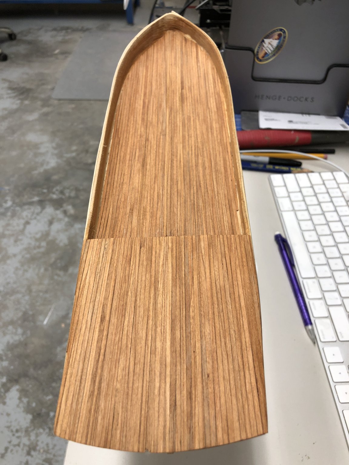
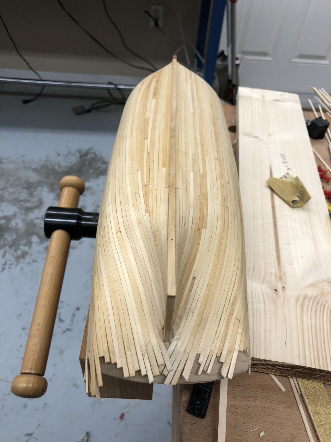
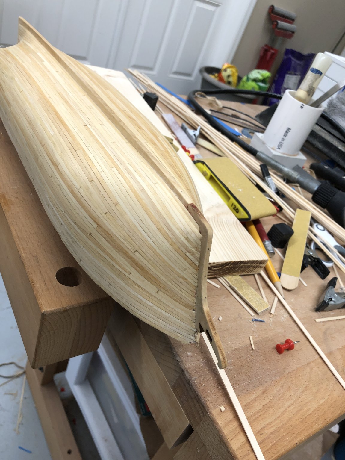
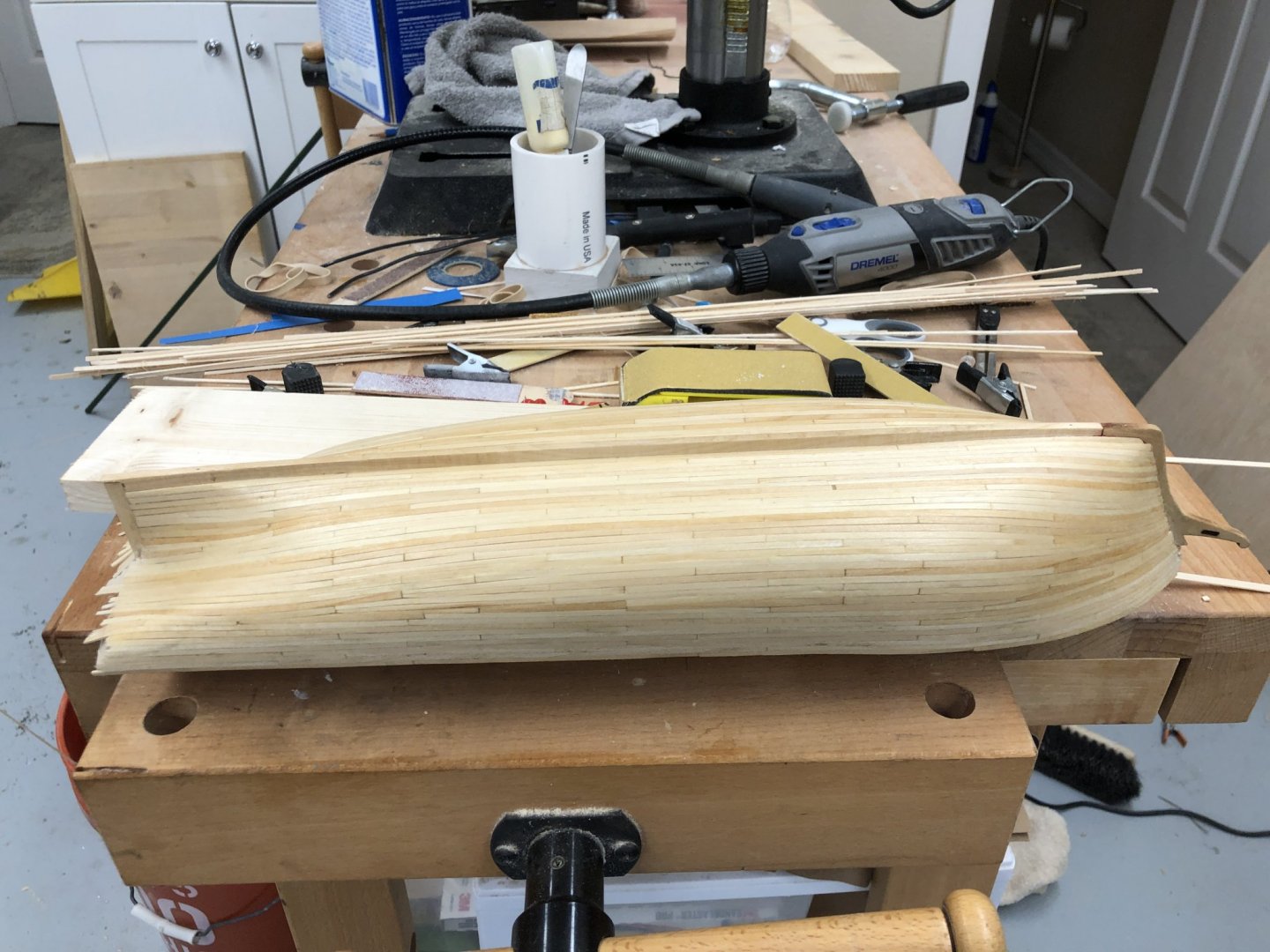
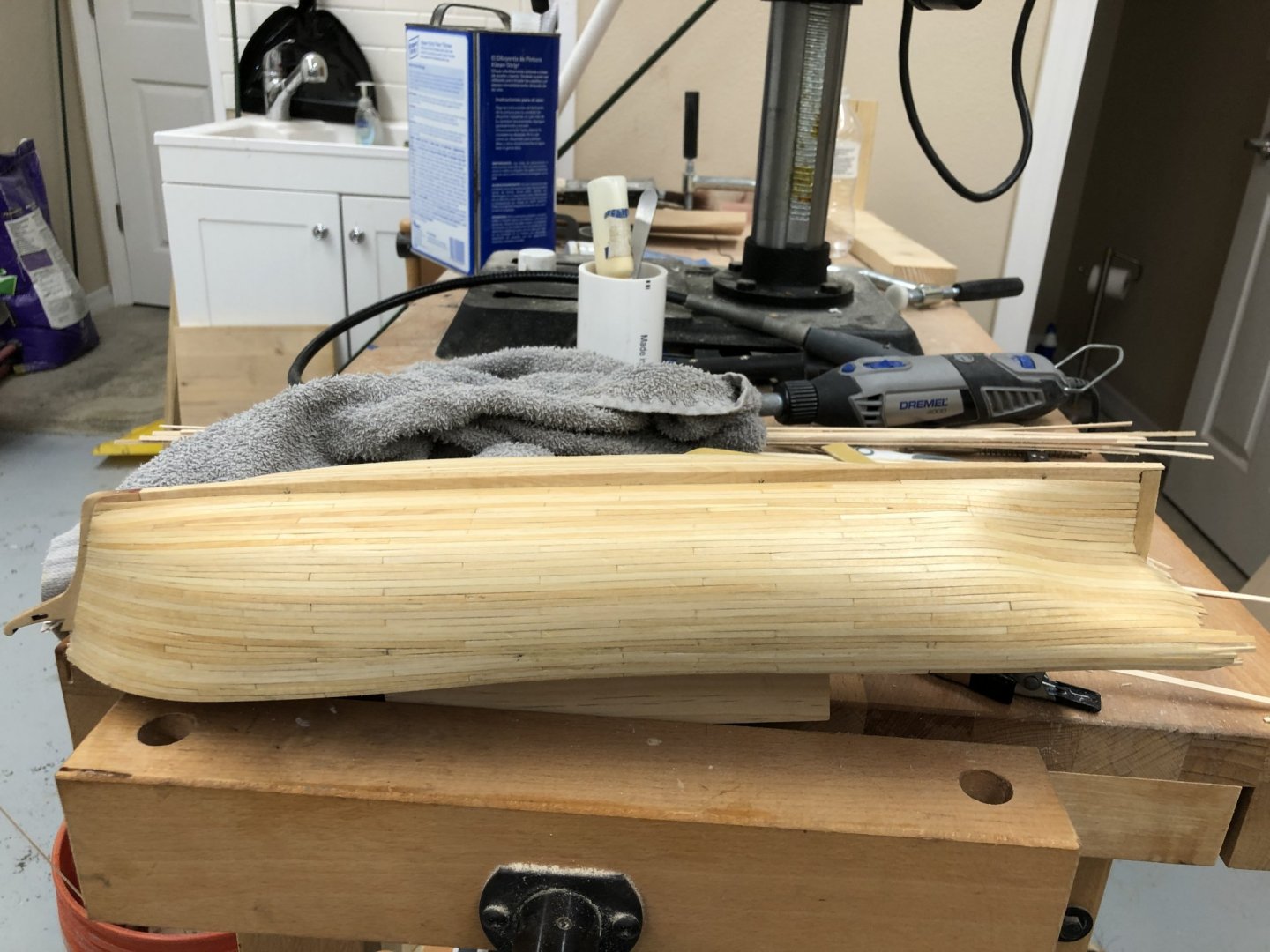
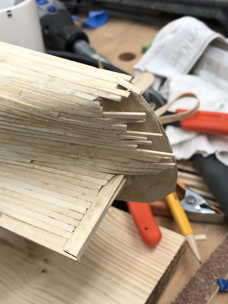
Hull planking is complete. I left the stern planks extra long as I think the transom installation is not done until much later. I will have to give some thought to how to protect the planks sticking out. Maybe I will need to amend the order of installation. Here is what the hull looks like after an initial sanding with 120 grit and a wipe down with paint thinner.


- 166 replies
-
- 6
-
-
- fannie a gorham
- finished
- (and 1 more)
-
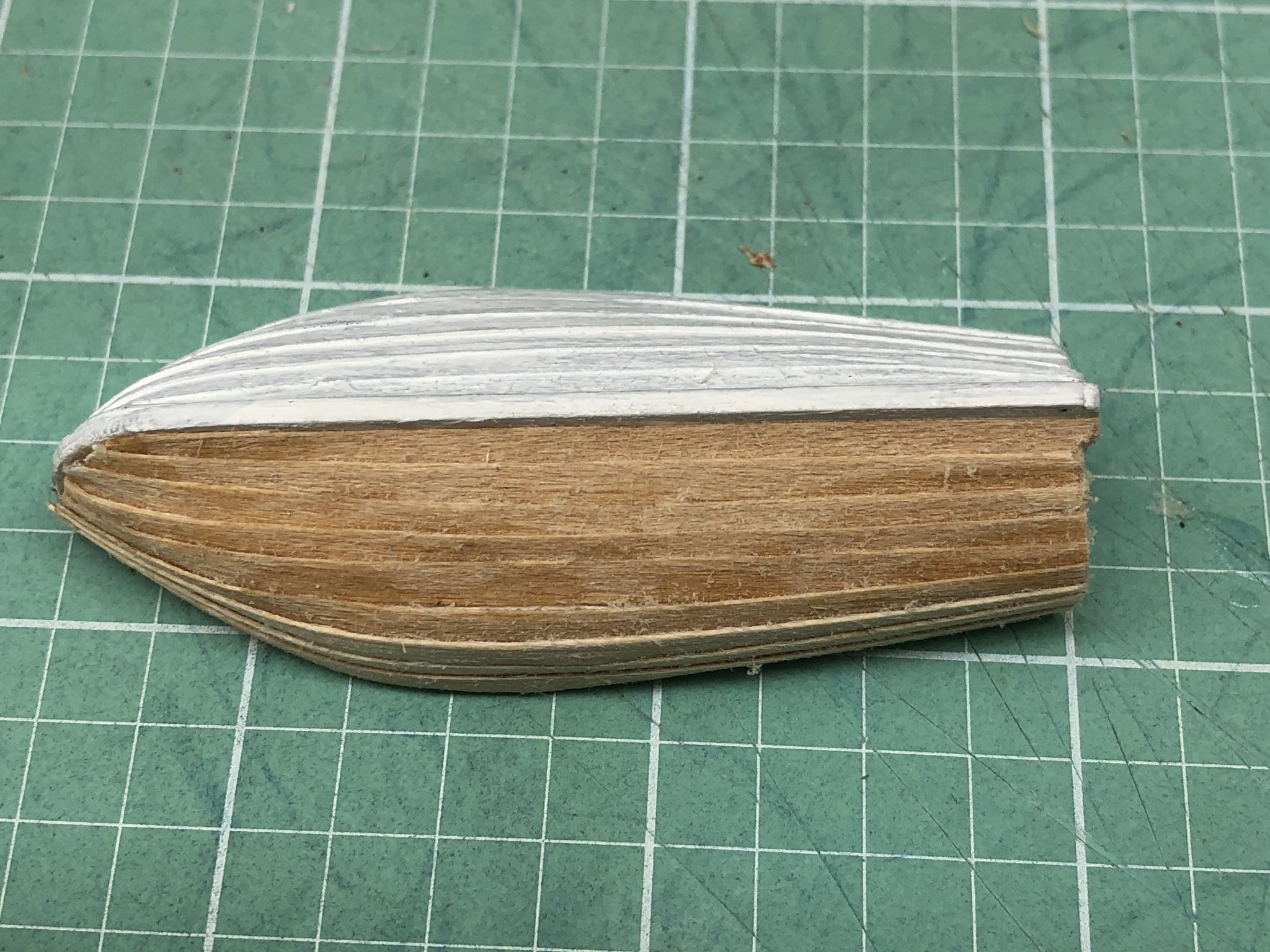
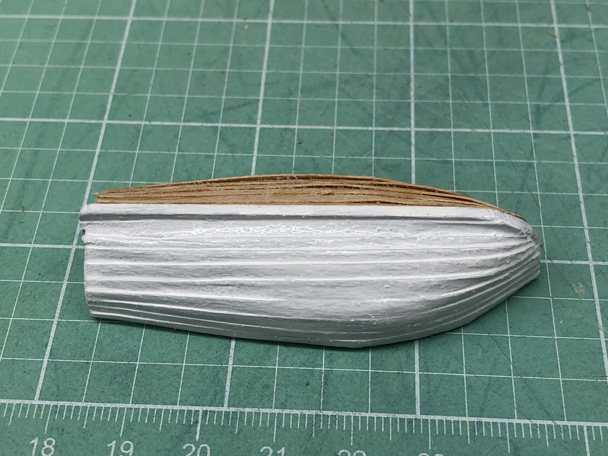
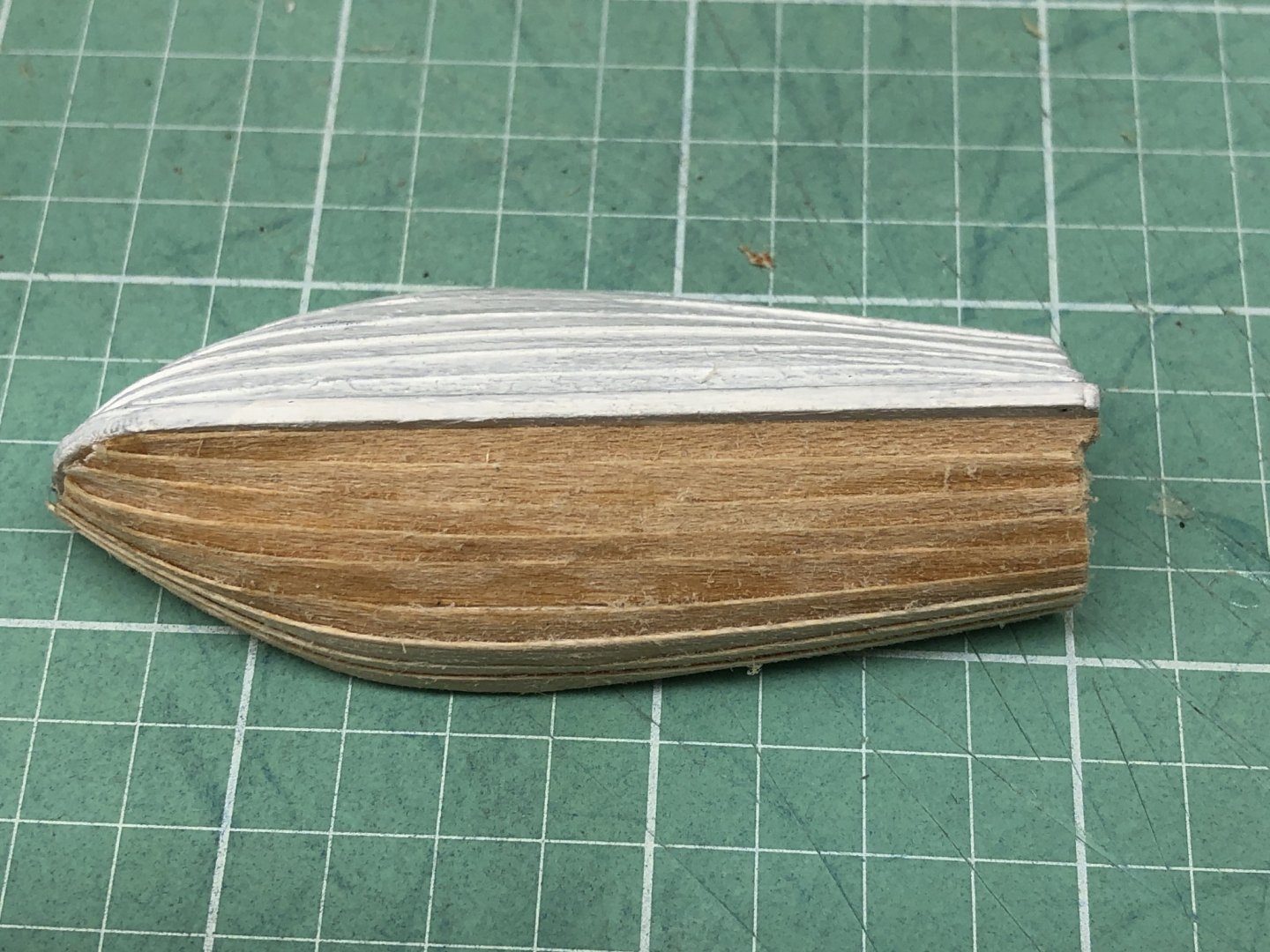
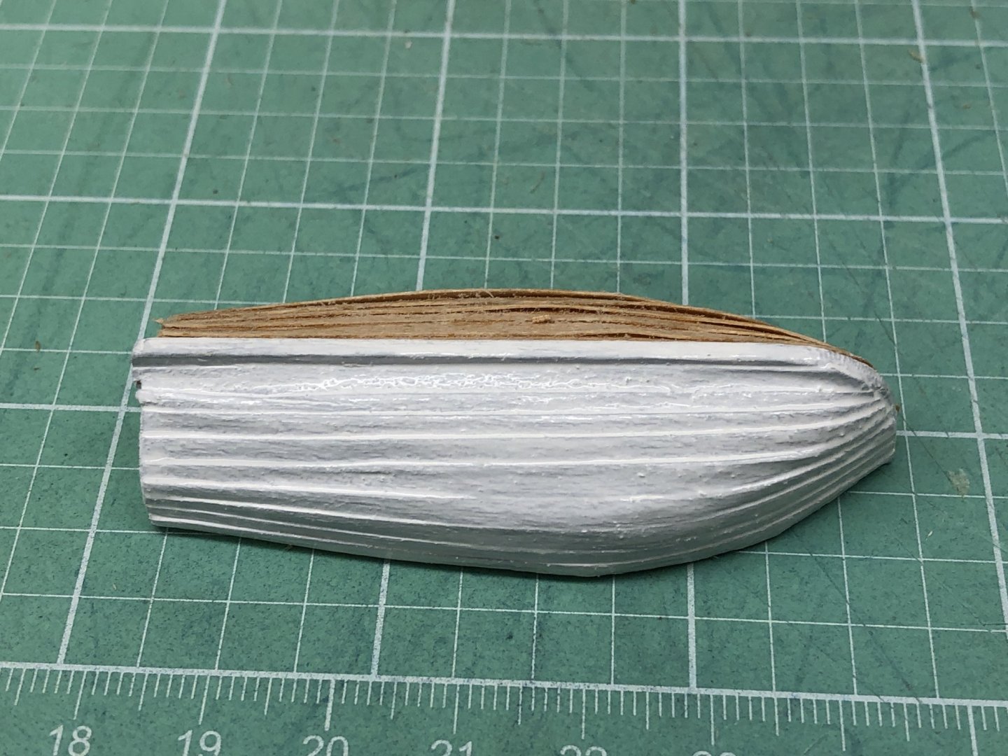
I decided that the ship's boat I built from the Model Shipways kit did not have enough "character". I had attempted to getn the "clinker" look to the yawl on the Niagara I built without success so decided to try it again. I used HO scale 1" X 8" (they come in 11" lengths) from Northeastern Scale Lumber for the planks. I reality it is really thin, probably just over 1" at 1/96 scale (since HO is 1/87) but close to 1/64" in use. Here is how it looks with one side painted and the other bare. I will paint the other side in due course. It needs a bit of sanding - 400 grit or less. As I said it is really thin. I also need to fab the cradle, eyebolts and tie downs but that is all on the "To Do" list with a myriad of other tasks.
- 166 replies
-
- 3
-
-
- fannie a gorham
- finished
- (and 1 more)
-
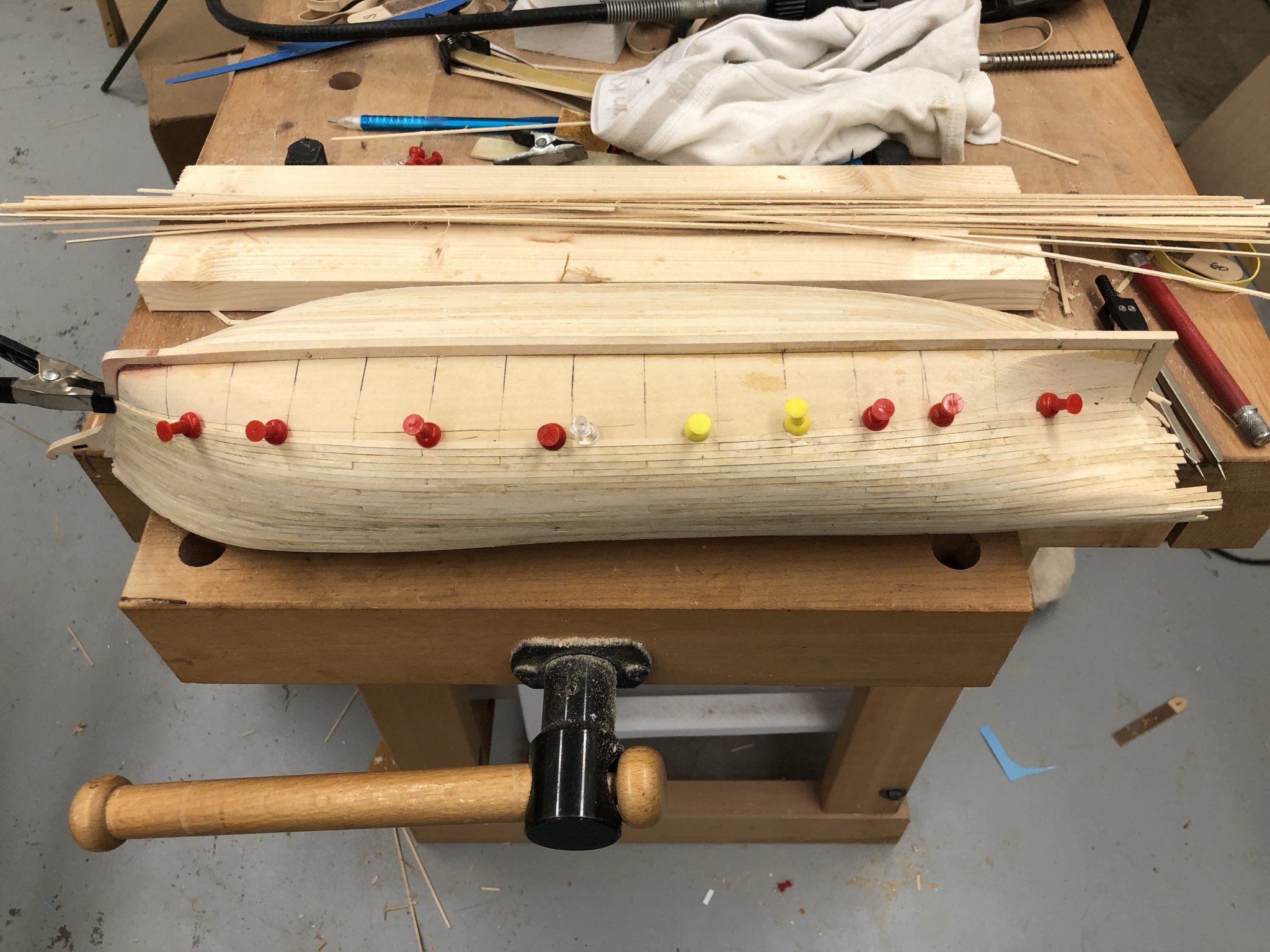
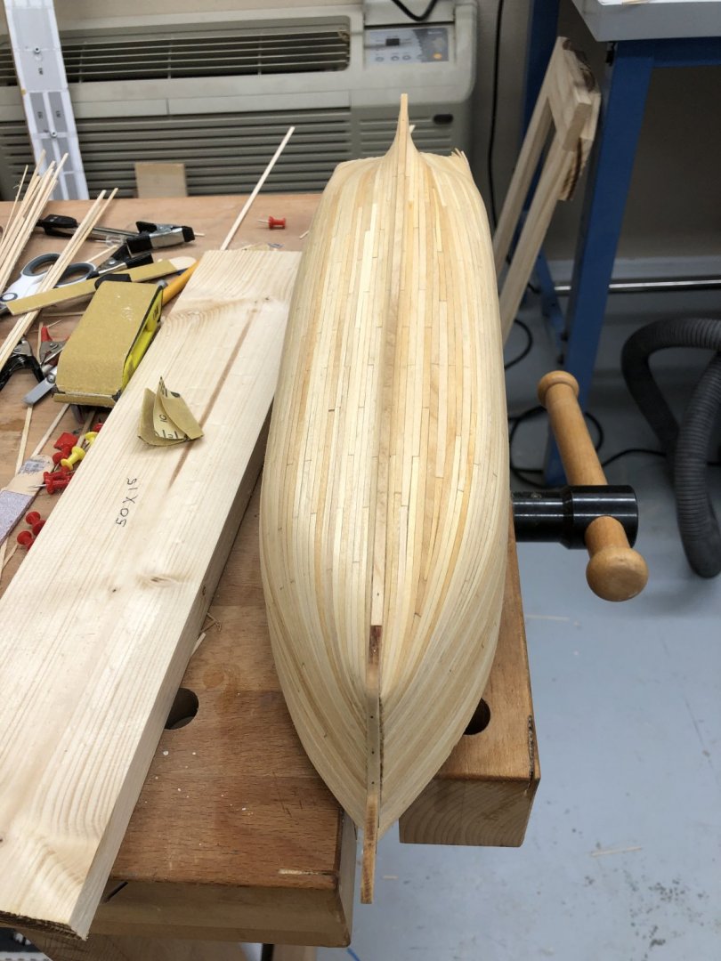
With 22 rows completed I turned the hull over and will start planking from the garboard strake up to meet just below the turn of the bilge (where any "extraordinary" measures will not be too easy to observe). One of the advantages of the shallow draft hull.

- 166 replies
-
- 3
-
-
- fannie a gorham
- finished
- (and 1 more)
-
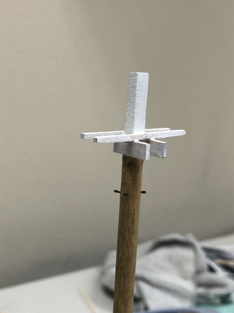
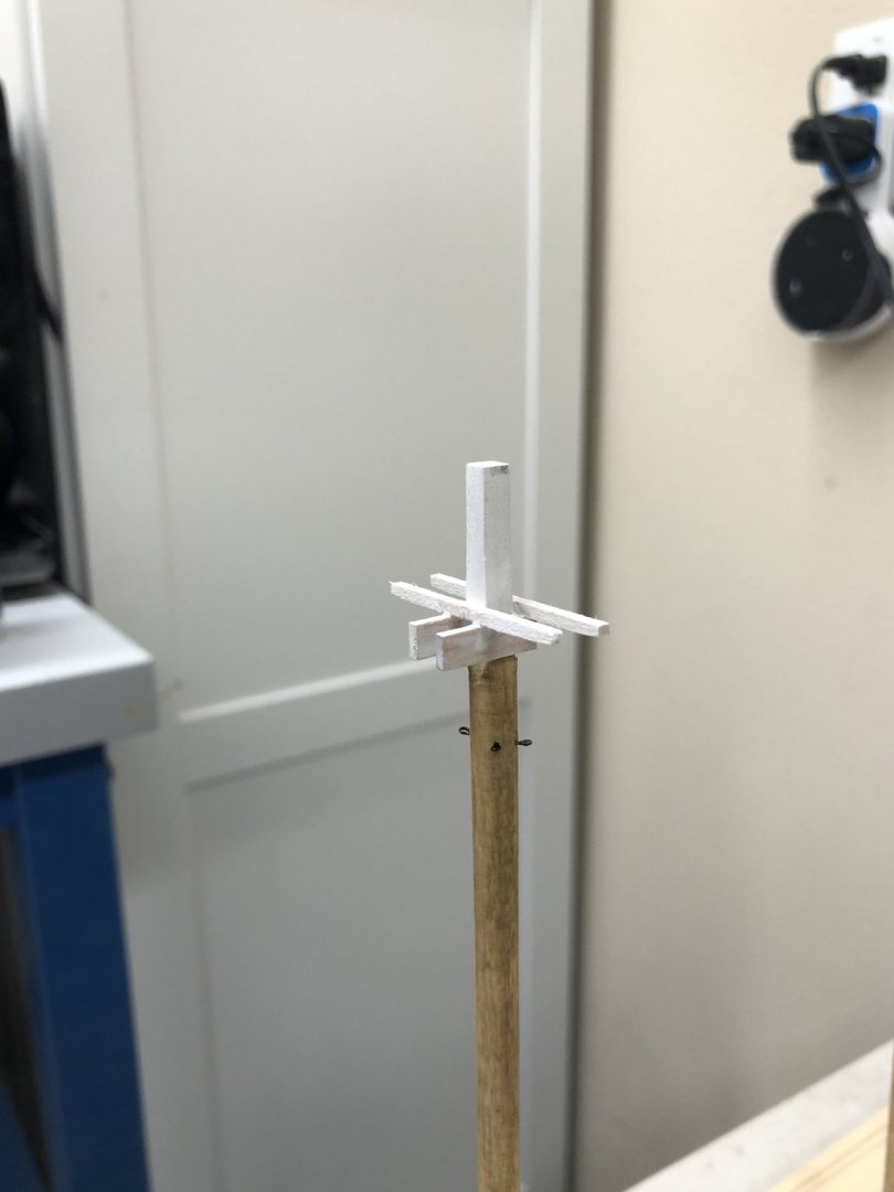
Waiting for glue to dry - added cross and trestle trees to Fore Mast. Futtock shroud attachment eyebolts and holes drilled in cross trees. Attempting to form eyes in .013 wire, pass through holes in cross trees then secure (somehow) to eyebolts on mast. Keeping wire straight will prove a challenge. Added white paint to mast top and when that dries will see how the wire rigging goes. Clearly another coat of paint and some fine sanding is required.
- 166 replies
-
- 3
-
-
- fannie a gorham
- finished
- (and 1 more)
-
After looking at the hull with the top band planked and taking some measurements I decided to try a few rows of full size planks to see how things went. I got five more rows done and noticed things getting a little close at the bow so I started to taper the planks forward of about station 5. Here is what it looks like with 17 rows completed. I am going to do a few more from the top and then start with the garboard strake and work up.
- 166 replies
-
- 2
-
-
- fannie a gorham
- finished
- (and 1 more)
-
While waiting for Santa to arrive I managed to get band 1 of the stbd side completed. Going forward I will use my proportional dividers rather than trying to match tick marks on the hull. I also made up a simple jig to assist in cutting the planks to size. Given where I am now it might have been a better idea to start with 1/8" rather than 3/32" planks. Even though 1/8" would be 12" at scale it seems that the max width is only "in play" in fairly short sections.

- 166 replies
-
- 3
-
-
- fannie a gorham
- finished
- (and 1 more)
-
Alternating between hull planking and spars. Have the three booms completed with sheet block (3/16" Triple) and an eyebolt at the end for the topping lift. I suppose the topping lift lines might be just fastened around the boom with an eye but an eyebolt will make things easier and they might have been that way also. I am going to add the holes in the jaws for the belaying pins for the topsail lines even though I have not decided yet whether to include those lines in the model.

- 166 replies
-
- 2
-
-
- fannie a gorham
- finished
- (and 1 more)
-
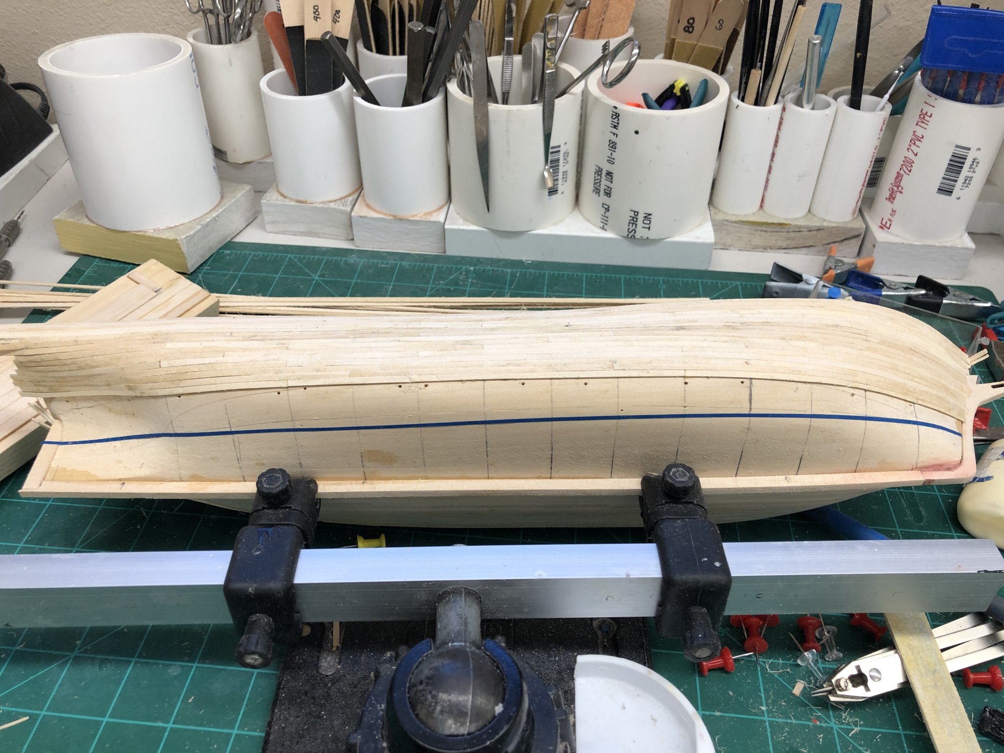
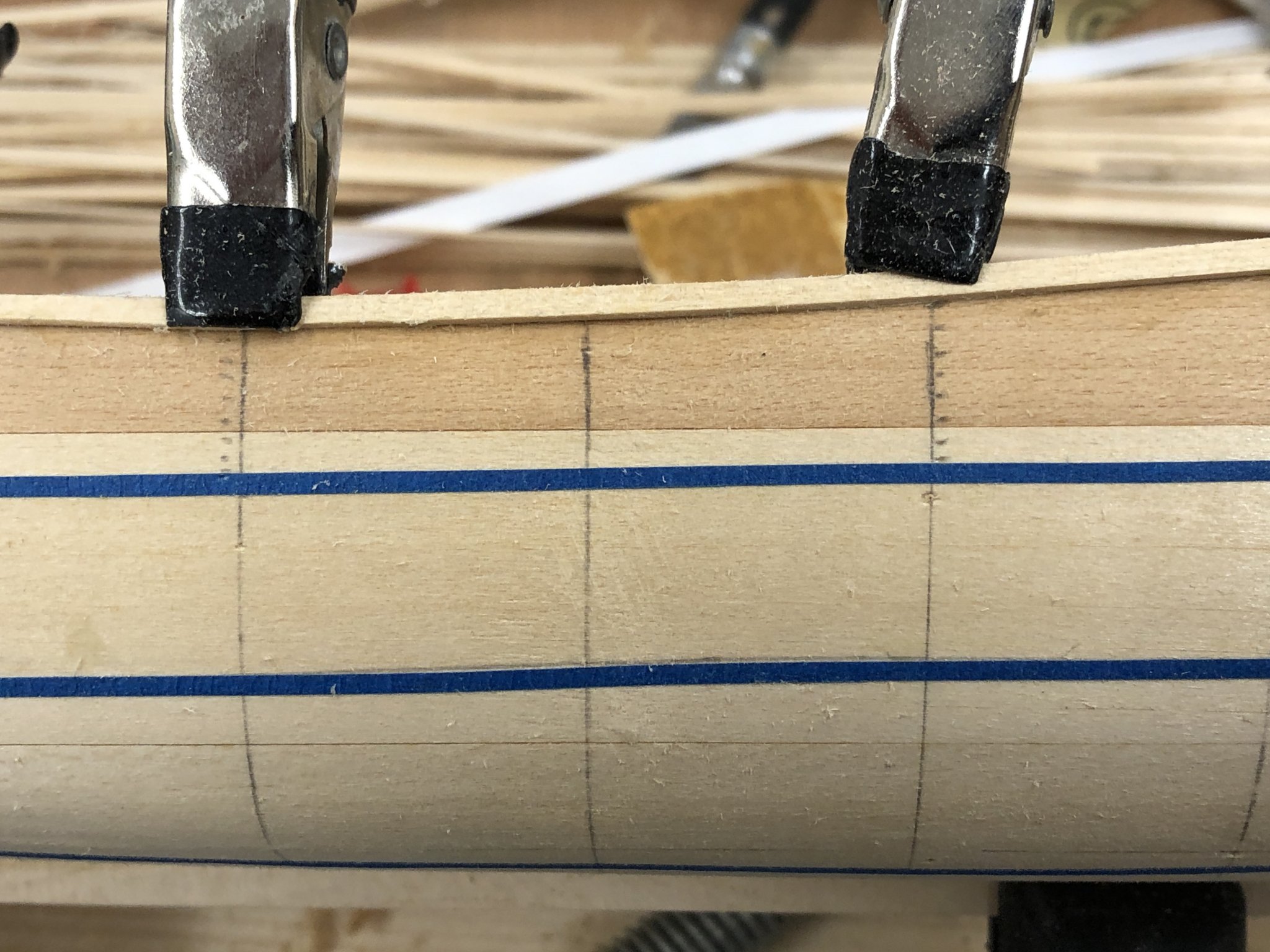
For the starboard side I am following the more conventional approach that is outlined in several places (including here:http://modelshipworldforum.com/resources/Framing_and_Planking/Lining Off your hull for planking). The starting point is determining the number of rows of planking required. At the widest point (which is a bit forward of amidships due to the rising bulwarks) it is 3 1/2" which will take 38 planks 3/32" each. So the total, number of planks is 38. Two (the top two) bands of 9 and two bands of 10 (bottom two - based on an eyeball estimate of which are the widest of the four). Now to determine the plank widths at each "bulkhead" (which is this case is every other station line). I decided to only do one band at a time, starting with the top one. This way I have a known starting point for the next band - I am not sure I can "hit the marks" every time so I need some "wiggle room" about exactly where the next band will start. After marking the plank widths I got the top row of the upper band in place. Based on measurements the planks are full width until about the fourth station then taper to about 2/3 the width amidships and just over half at the stern. At the bow I am just butting the planks into the ones sticking out from the other side. This will have to be cleaned up later and the hole for the bowsprit fits in here too somewhere.

- 166 replies
-
- 2
-
-
- fannie a gorham
- finished
- (and 1 more)
-
Mark - I will try and do a better job of explaining what I did for the starboard side. Before I installed the keel and stem pieces I sanded a small bevel where the pieces would meet the hull to get a rabbit for the planks to fit. I did not make the bevel very large as the planks are only 1/32" thick. As far as a bearding line goes, I sanded the stern area to 1/16" (evenly distributed on each side) less than the 1/8" stern post width. Doing this by working toward the stern along the hull pretty much defined a bearding line although I did not do anything explicit to define one. With a 1/32" gap between the solid hull and the stern post on both sides the planking would be flush with the stern post.
-
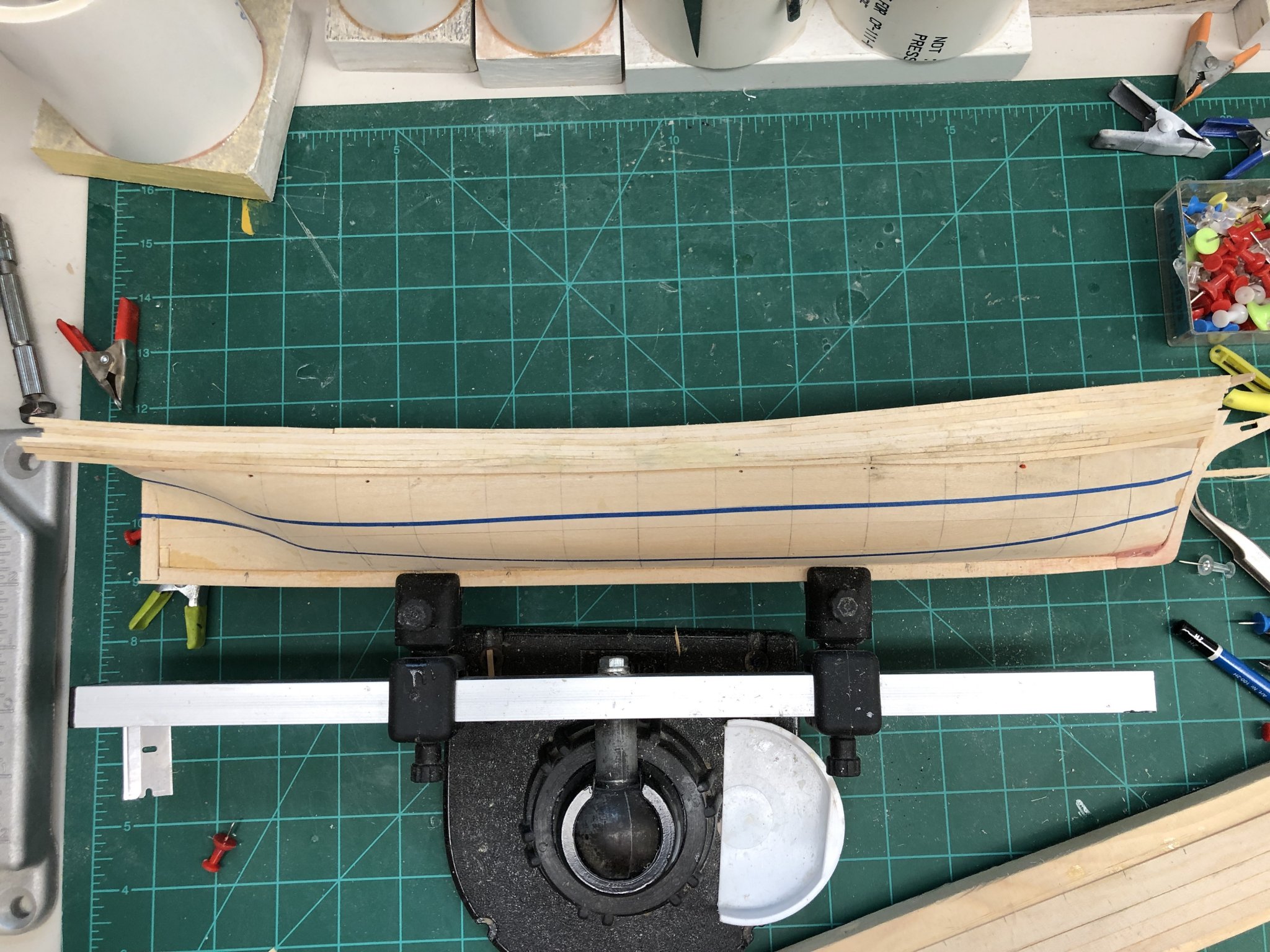
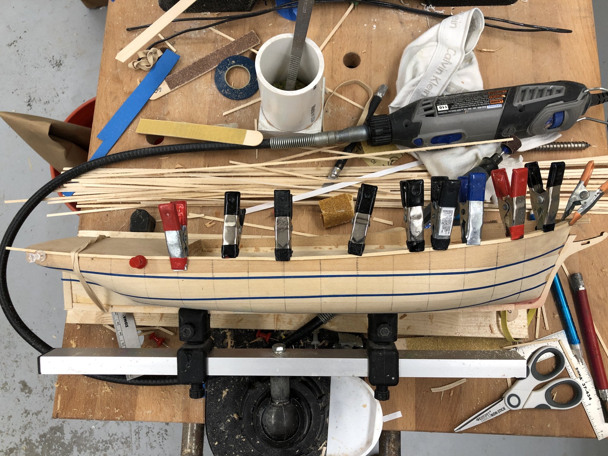
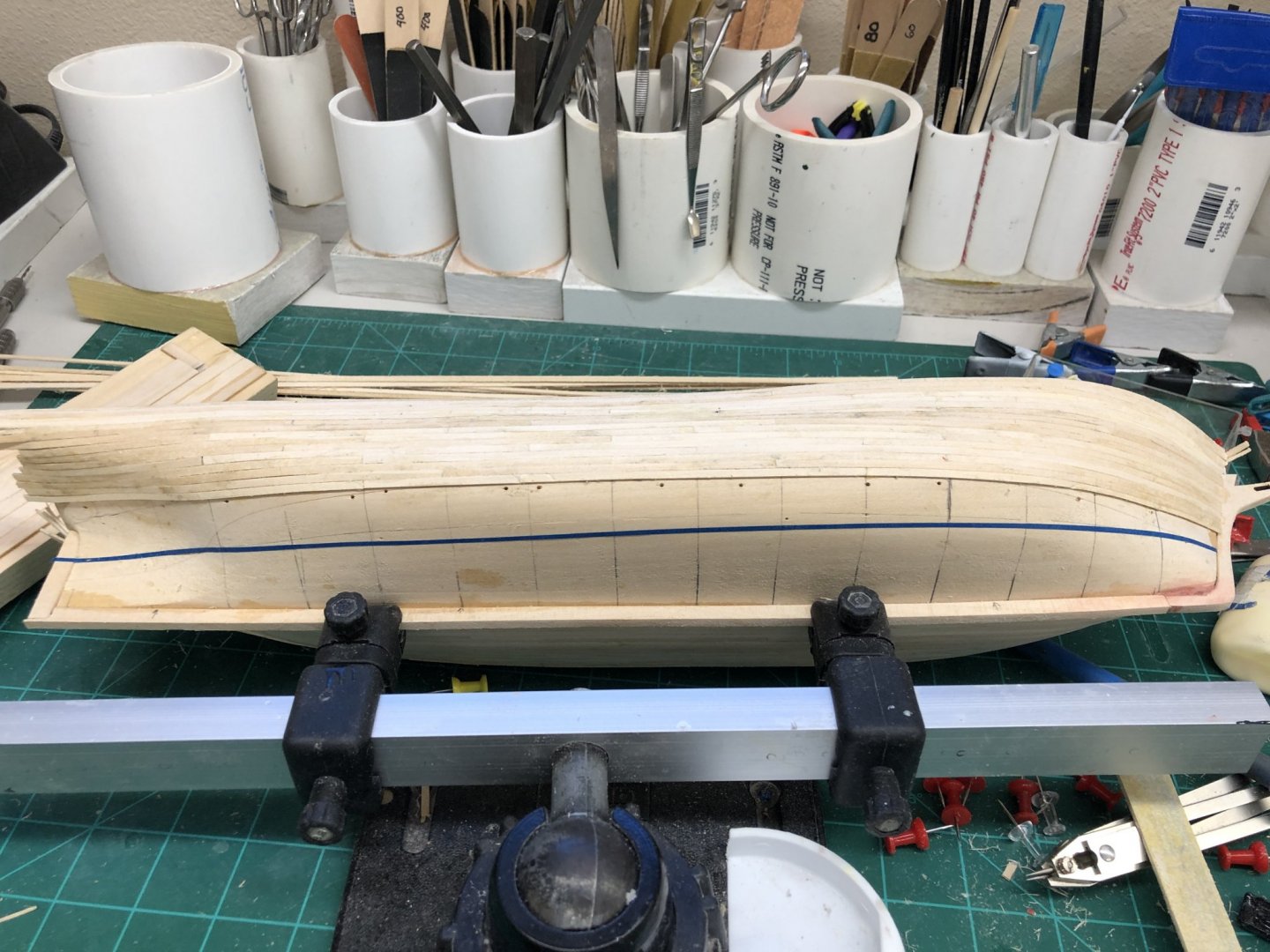
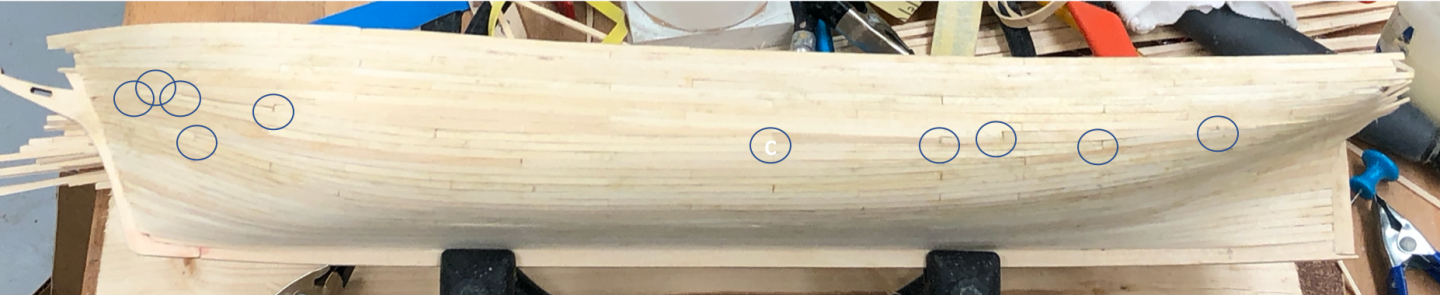
Back from cruise (weather was pretty rough last two days - of seven so overall pretty nice). Just as I was going out the door I got the planking on the port side finished. Not the best job I ever did. I ended up with a bunch (see blue circles below) of dropped planks in the middle where the two belts came together and had to use a few 1/8" wide planks to avoid other issues. I was just "laying planks" and tapering where it seemed "right" as I moved along. Probably not the best approach but I wanted to see just how difficult the planking would be. (On Endeavour this approach worked perfectly - the only tapered planks were the last ones on each side but you only get that lucky once a lifetime I think - too bad I was not gambling at the time.) The stern is still a work in progress. I do not plan on doing anything more there until both sides are done and I see where the laser cut transom piece "fits in". For the stbd side I am going to proceed in a more conventional manner, laying out planking bands and calculating plank widths as I go along. More or less what you would do for a POB hull. Not sure it is going to look all that much better than the port side once both are sanded and a few small areas patched but we shall see. My major intend with planking over the solid hull is to get as much of the planking to show through the paint as I can without any grievous errors in the planking showing as well. Probably will not know how well I accomplished that goal until much later. I plan to sand (lightly) the hull (both sides) starting with 100 grit and going to 220 and 320 before I put on the primer. What I do after that will probably depend on how it looks after the primer. I gave some thought to colors while on the cruise and since I already have two models with black hulls (Bluenose and Ben Latham) and two dark green (Niagara and Pride of Baltimore) I think I am going to paint this hull a medium gray (with anti-fouling red below the waterline). I think I will do the cabin roofs in a lighter gray and the bulwarks in white. I just got the wood to plank the decks in cherry and probably will do the main rail in cherry as well.
- 166 replies
-
- 4
-
-
- fannie a gorham
- finished
- (and 1 more)
-
Signing off for a week to go cruising toward Central America. And then it will almost be Christmas.... Probably not much is going to get done before the 27th or so.
- 166 replies
-
- 1
-
-
- fannie a gorham
- finished
- (and 1 more)
-
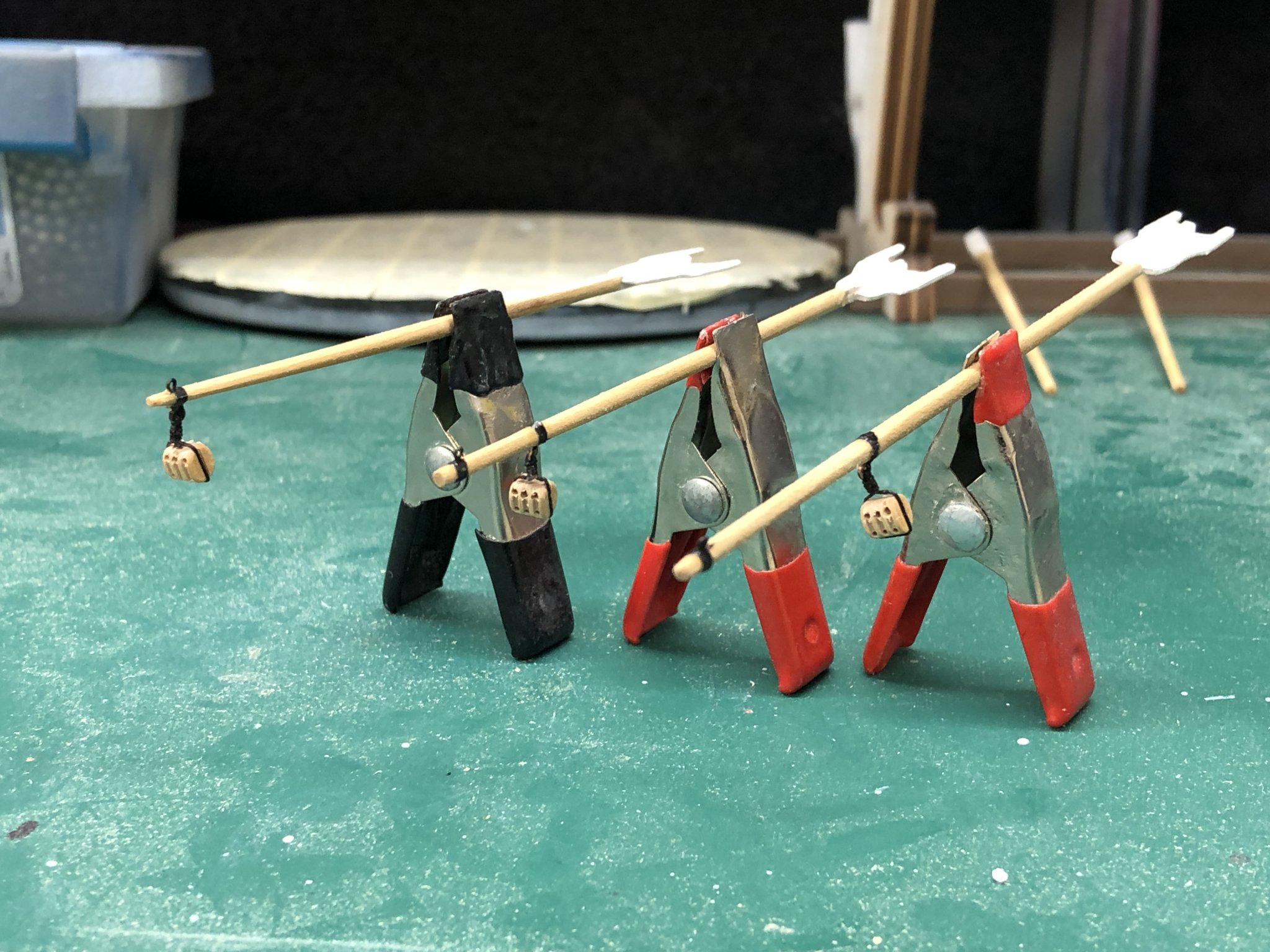
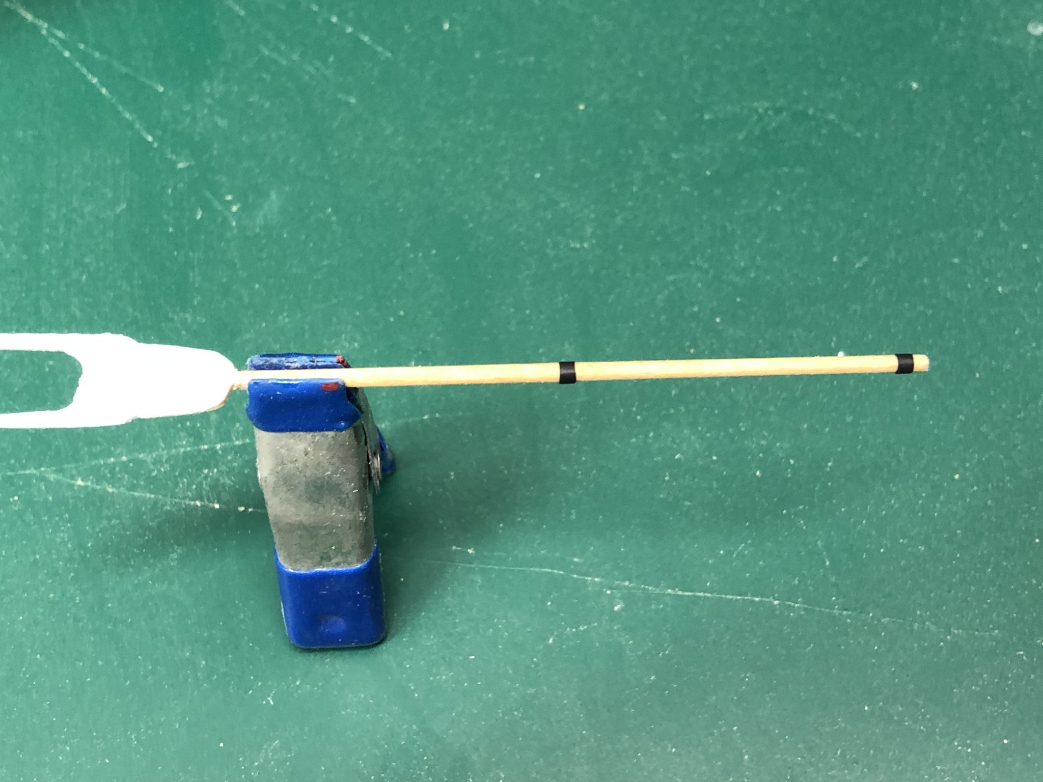
Speaking of striping tape used for the spar bands - the adhesive on the tape does not last forever sitting in the shop. Likewise it probably will not last forever especially on these very thin spars like the gaffs. I put some flat clear acrylic over the tape to seal the edges and hopefully keep it from peeling up in the near future. And it takes the shine off the tape. So far the tape does not appear to any the worse for the experience but I am going to give it a few days before I do the rest of them.

- 166 replies
-
- 2
-
-
- fannie a gorham
- finished
- (and 1 more)
-
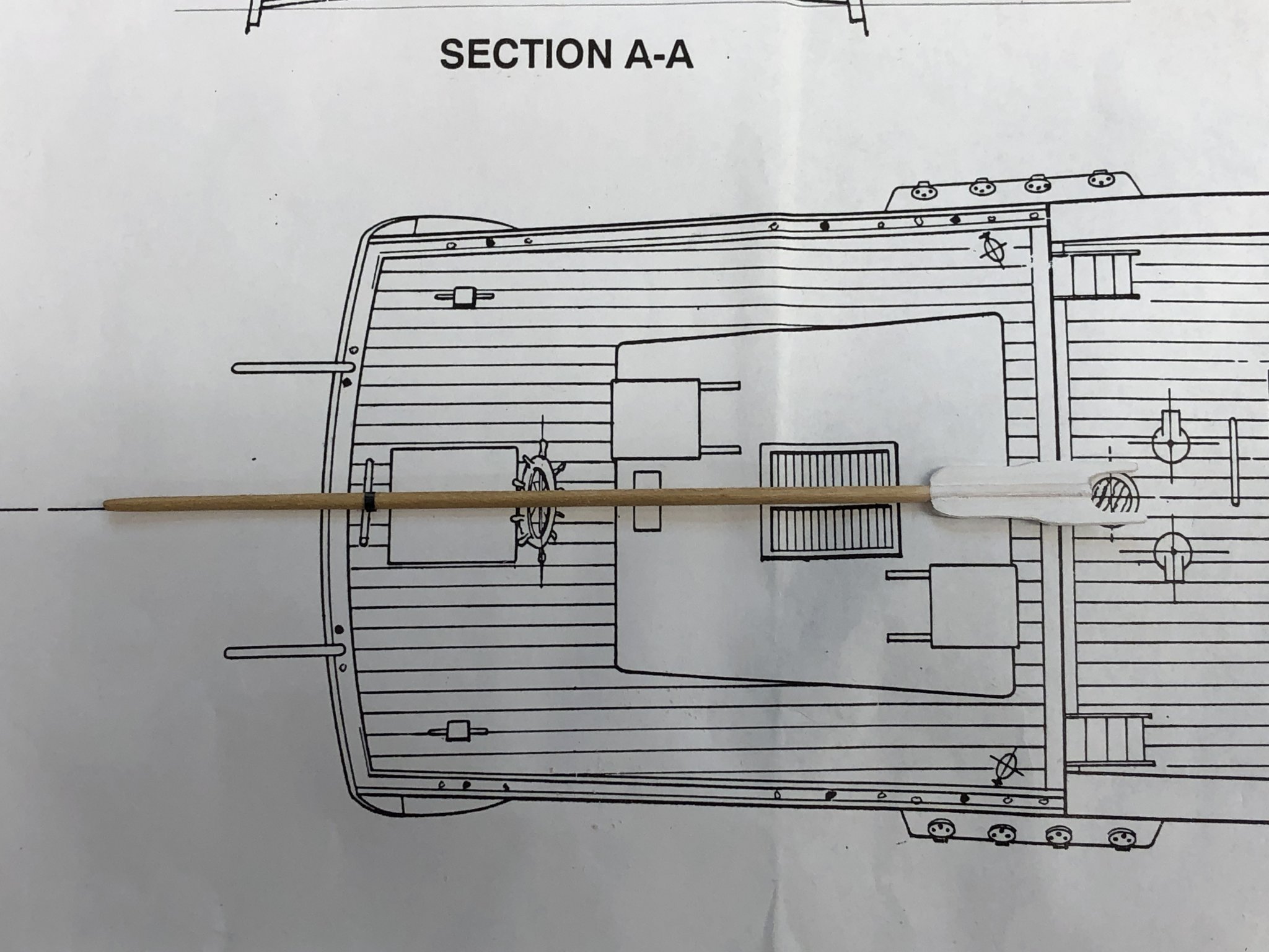
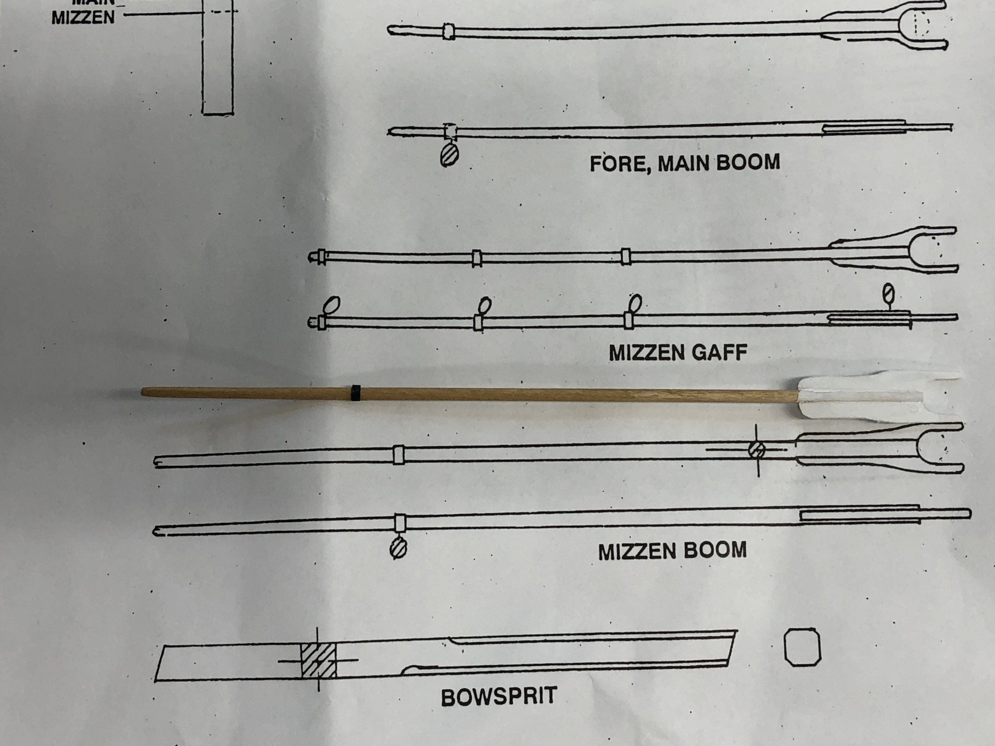
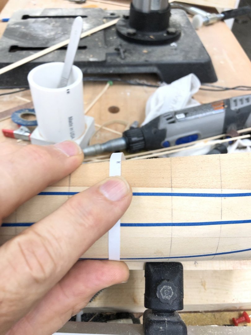
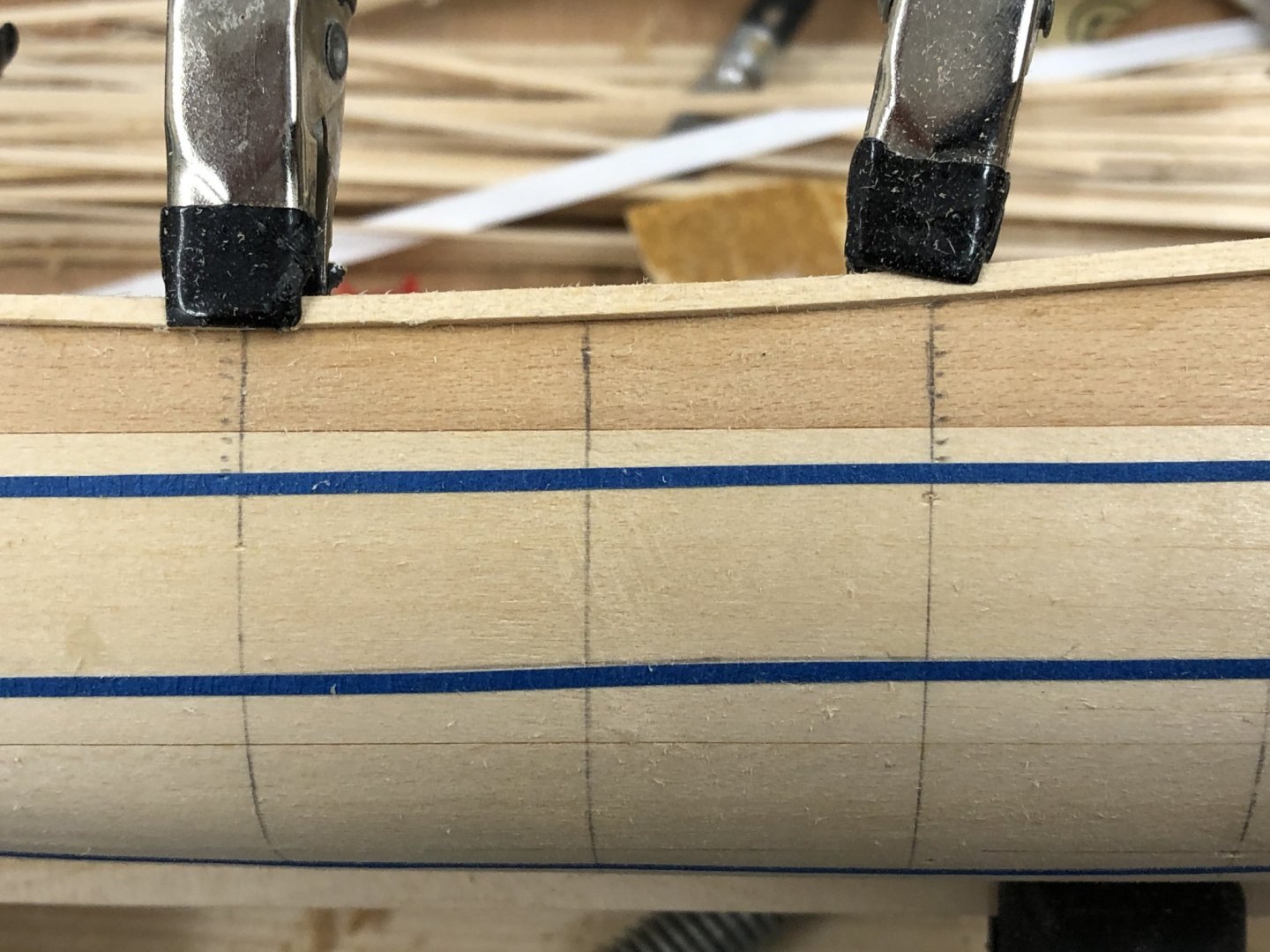
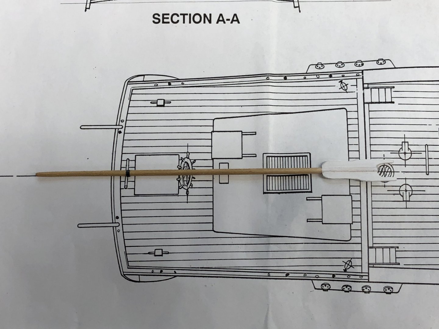
Working the spars for a break from planking - hull is nearing completion on the port side. Spars have been fabed per sheet 3 of the drawings. I was starting to put the striping tape on to simulate the metal bands where the eyebolts will be located when I came across some inconsistencies in the drawings. Below are parts of sheets 1 and 3 showing the mizzen boom. On sheet 1 is the quarterdeck and I put the Mizzen Boom where is appears it should go. The black band on the spar is the tape that I put on based on this drawing. The second picture shows my Mizzen Boom on sheet three which has the spar details. Clearly the band is incorrectly located on one of these - I looked at the hull and placed my bet on sheet 1. There is a similar issue with sheet 2 and 1 with respect to the boom tackle locations. Sheet 2 shows the Fore and Main Sail sheet tackle at the very end of the boom but the spar detail drawing shows the main sheet (and fore sheet) tackle some distance forward of the end. In this case sheet 2 is probably correct as the main sheet traveler is shown on sheet 1 to be forward of the bilge pumps which are close to the end of the main boom. However, it appears that for the Fore Boom sheet 2 is incorrect as it appears that tackle should be very near the end of the boom. Hopefully the next person to build this kit can take advantage of these issues rather than find out when installing the running rigging. Probably not really significant issues - have the tackle lead a bit forward (or aft) of vertical would not even be noticeable as we are o nly talking a small fraction of an inch.

- 166 replies
-
- 2
-
-
- fannie a gorham
- finished
- (and 1 more)