


SJSoane
-
Posts
1,641 -
Joined
-
Last visited
Content Type
Profiles
Forums
Gallery
Events
Posts posted by SJSoane
-
-
I would add that cutting the thin piece on the fence side means that you cannot easily use a push stick. I use one that hooks over the fence, and has some sandpaper on the bottom surface to grip the stock. It keeps the stock flat on the table, and tight against the fence. this helps avoid any vibration in the cut. But this needs enough stock between the blade and the fence to give clearance for the push stick. Much easier and safer to cut the thin piece off the blade side, and then index the fence over with the stop for the next cut.
Mark
-
Michael,
I keep forgetting that you are actually going to sail this. A whole new set of complexities!
Mark
-
-
Beautiful work on the stern framing, Mark. I guess that if we knew how the old shipwrights did it, we could duplicate their methods and make modeling a bit easier on ourselves.

Thanks, Mark, don't you sometimes feel you are channeling model builders from the 18th century, when you make exactly the same piece you know they made 2 ½ centuries ago?
Just perfect, it looks better and better. Great work on the wood frame.
My admiration to your craftsmanship.
Kind regards
DorisThank you Doris, coming from you who is one of the very best builders on this site, this is a very high compliment!
-
Michael,
Just scale up those metal fitting to full size, and you could open a boat chandler shop. Can you do a line in flotation devices? ;-)
Forging--beyond my comprehension how you do it, and do it so well.
Mark
-
Thanks, Michael. I don't know how I would have pulled this off without a jig. Each piece depends upon several other pieces to locate it, so everything is floating around without something to anchor it at least temporarily. And now the most important part--equal spacing of the window frames--is guaranteed by the original spacing in the jig.
I can only imagine how the original shipwrights located these two story tall counter timbers. There must have been lot of shoring and propping...
Mark
-
Beautiful, Alex, exceptional craftsmanship.
Mark
-
Hi Michael,
Your metal parts are so well done they look full scale; until I see your hand in the photo. Exceptionally well done!
Mark
-
-
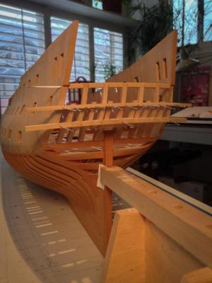
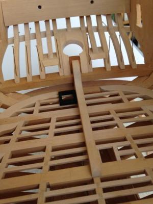
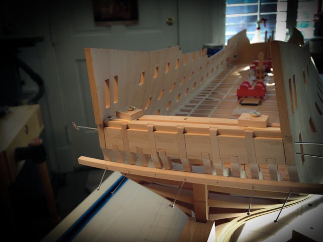
Hi everyone,
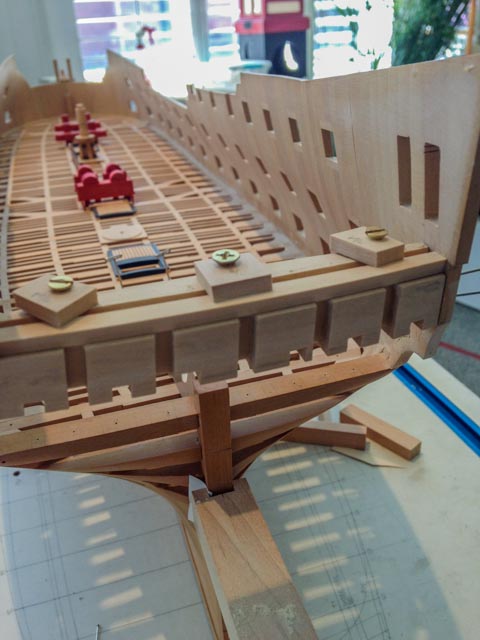
After many months, I was finally able to remove the jig today, and see the stern in all its glory.
I still have to trim the short pieces in the window sill area, and fair inside and out before finally gluing up and starting the transoms inboard. But it is definitely looking more like a real stern.
The whole thing is shockingly fragile. No wonder a broadside into the stern would just about finish the day....
Best wishes,
Mark

- Erebus and Terror, Elia, druxey and 18 others
-
 21
21
-
-
Michael,
Perfection! Your skills are astounding.
Mark
-
Hi Gaetan,
I had heard of those Gary Fong light diffusers, but didn't know how it would help with photograph of models. Now I see. Thanks!
Mark
-
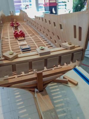
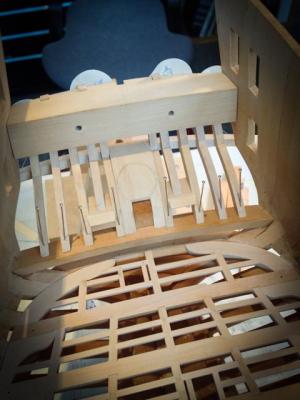
Hi everyone,
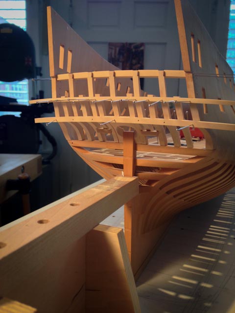
A little more progress. I used the jig to shape the quarterdeck transom, by gluing sandpaper on the upper surface of the jig to fair the transom to it. I also fitted three clamps to hold the transom in place while I marked the dovetails with the vertical counter timbers. The first photo shows the transom before dovetailing, set forward from the aft face of the counter timbers so the frames for the lights can fit flush between the vertical timbers. The original Bellona model shows this offset between counter timber and transom, and it took me sometime to figure out; perhaps I'll do a drawing later to show this.
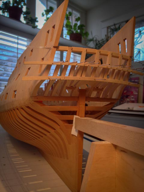
The second photo shows the counter timbers dovetailed into the quarterdeck transom. I only have to make the upper counter moulding, fair the faces of the counter timbers, and it is time to glue up! That will be another month at my current rate....
Mark

-
-
Beautiful work, Michael, as usual. And every step makes it look even better!
Mark
-
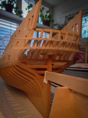
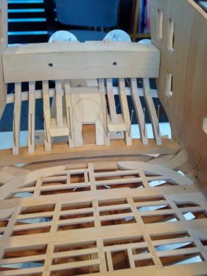
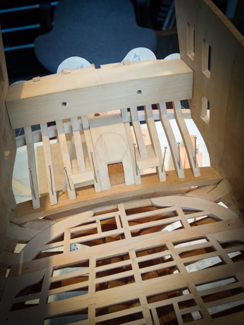
Hi everyone,
Quick update. I roughed in the helm port, which will be refined in size once I have a rudder to check against it. Getting this port shaped meant I could finally fit the center counter timber, which mortised into it. I don't know if this is the right joint here, but it made sense when I looked at it all. All pieces are now shaped and fitted. Time to cut the dovetails at the tops of the counter timbers, and fit the quarterdeck transom....
Mark

- garyshipwright, alangr4, mtaylor and 17 others
-
20
-
Thank you Adam, Sailor and Doris, for your kind comments. This really does turn out to be the most challenging part of the build so far, keeping track of so many parts all having to align to different angles and curves in three dimensions. I thought I had a good ability to visualize in 3 dimensions and to understand 2 dimensional drawings that represent 3 dimensions; but this stern goes entirely beyond my skill to visualize it. I had to start building to understand the interrelationship of the parts in 3 dimensions. All part of the fun!
And Doris, I appreciate your comment about wooden frame. Your build in card continues to amaze me; I am sure you have the more difficult material to work in, and you do it so exceptionally well.
Best wishes,
Mark
-
-
Michael, it is a joy to see your craftsmanship.
When I read your weather updates, I know what is coming our way down south...
Mark
-
Very nice, Remco, a level of detail not seen before. You will need to have a book of photos beside your ship when it is done, to show off all of the details...
Mark
-
Gary,
Beautiful, as always. I noticed the tubes between the pump cisterns. I hadn't seen that before. Very nice!
I still don't know where my helm port transom is going. I'll keep looking at yours very carefully as a source of inspiration.
Best wishes,
Mark
-
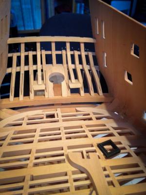
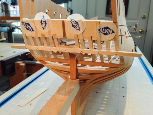
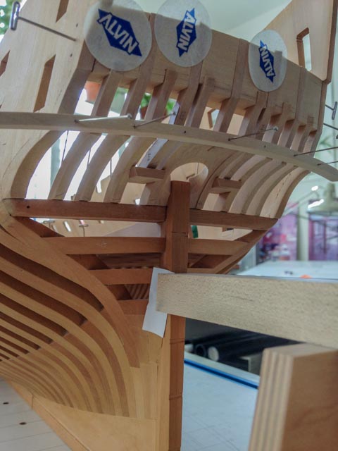
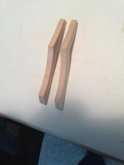
Hi everyone,
A quick update on the Bellona's stern. I don't get much time in the shop these days, so it is going very slowly.
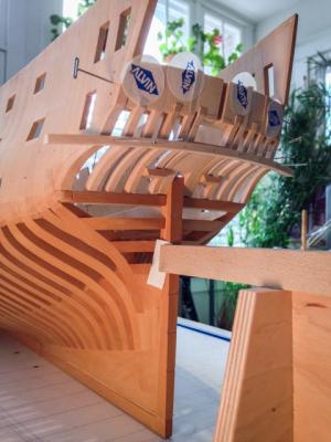
Fitting the counter timbers is trickier than I ever would have imagined. The counters round back and up, and the vertical timbers taper to point some distance above the hull. But not all taper. The ones on either side of the stern post are vertical; and the ones on the outboard side of the gunports are vertical alongside the gunport and then crank to align with the taper of the others above the gunport. I have shown these cranked timbers in the first photo.
Everything is loosely fitted right now, and not yet sanded to final fairing. I haven't yet figured out the rudder port shape, so it is just a slab sitting in the place where chocks will have to go, with a penciled in shape of the port. I may build the rudder next to see what the shape of the port will be.
It is pretty thin construction here. I can see why a broadside raking the stern would devastate the decks.
Good thing I am not in a hurry, and don't have any raking broadsides coming my way yet...
Mark

- daHeld73, harvey1847, WackoWolf and 18 others
-
21
-
It is always a pleasure to see your work under construction....
Mark


Bristol Pilot Cutter by michael mott - 1/8 scale - POF
in - Build logs for subjects built 1851 - 1900
Posted
Hi Michael,
I am not getting much time away from work to check on the website lately, but I did stop in to see your progress. Looking great!
Mark