
MORE HANDBOOKS ARE ON THEIR WAY! We will let you know when they get here.
×


captainbob
-
Posts
3,498 -
Joined
-
Last visited
Reputation Activity
-

 captainbob got a reaction from Bedford in Maine three-masted schooner by Bedford - 1:54 - RADIO
Making RC sail boats work rigth usualy requires thinking outside the box. Sounds like you have a winner.
Bob
-
 captainbob got a reaction from Don9of11 in Draftsight Question
For many years, I used both AutoCad and SolidWorks when I was working. Now I run DraftSight on a cheap Toshiba laptop with Win7 and have no problems. If you want to continue with DraftSight you should contact their tech support.
Bob
-
captainbob reacted to Omega1234 in Ingomar by Omega1234 - FINISHED - 1/278 - Hereshoff designed schooner
Thanks Elmer Cornish and everyone else!
Here are some of the latest photos. The first few show the hull with the deck template and the side of the hull being prepared for opening up, so that the internal accommodation can be eventually viewed. The rest of the photos show the hull after the frames have been cutaway. Luckily the hull is structurally strong enough to withstand the hull's side being cut open in such a way. Not for the faint hearted, because, once it's cut, there's no turning back!
Anyhow, enjoy the photos.
Cheers
-
captainbob reacted to Bedford in Maine three-masted schooner by Bedford - 1:54 - RADIO
Ahh so that's a clapper. I was thinking of lining the rubbing edge of the yolk with a brass wire to reduce friction but my son and I put some thought into it and came to the conclusion that the best way to reduce friction is to reduce the number of items causing friction so I removed half of the hoops so now there is one every 40mm instead of every 20mm and this has helped the sail itself go up and down the mast.
Then instead of running the lazy jack through loops every 20mm on the sail I reduced it to just three loops, this dramatically reduced friction there and while the sail is not as controlled as it is hauled down it is still managable. You will see that I also moved the point of attachment on the gaff forward to a point that equalises the down pull so it happens smoothly without the outboard end of the gaff heading down first which caused the yolk to jam on the mast.
The other step was to add a lanyard from the master block on the gaff halyard to the yolk on the gaff, this ensures the gaff pulls up at the correct angle, again, preventing it from jamming on the mast.
The result is a sail that can be raised ad lowered very easily.
-
captainbob reacted to pete48 in Muscongus Bay Sloop by pete48 - FINISHED - SMALL
Today I decided to work on the Cockpit Floor for Keel # 4 , I first laid out the Cockpit Floor so that the Bildge could be accessed, Then figured out where the Bench would go . I then cut out strips of 1/64" Birch ply and roughed in the Pieces. Then fine tuned them Painted the edges Black ( I got a little sloppy ) and glued it up . This is the First one I have done like this . I will do the same for the Fish well Deck . I did start to cut out the bench sides and proped them up for the Photo. Here are the results
-
captainbob reacted to Jim Lad in Francis Pritt by Jim Lad - FINISHED - Scale 1:48 - Australian Mission Ship
Well, it's been a lonnnnnnnnnnng time since I've posted an update. This is partly due to the fact that not a lot of progress has been made, partly because I've missed a couple of days at the museum and also partly due to the fact that I keep forgetting to take my camera with me when I go in to the museum!
A few more frames have been raised and hopefully the framing will go a little more quickly from now on. I'm finally at the stage where the remainder of the frames are rough cut, so while I'm waiting for glue to dry on one frame I can be finishing the next one ready for fitting.
A couple of frames are going to need adjustment at the fairing stage as, for some unknown reason they're slightly too long - but too long is easy to cut down at the final fairing stage.
John
-
captainbob reacted to pete48 in Muscongus Bay Sloop by pete48 - FINISHED - SMALL
Today I finally got the final coats of paint on Keel # 3 for a total of 9 including 2 coats of primer, I got that fiberglass gloss that I was hoping for, I then shaped the rudder and sprayed 2 coats of primer. I then turned my attention to Keel # 4 I first installed the winow glass . ( I use the plastic from X-Acto blade refill packages ) I then made the cabin top, the hatch rails ( I found a unique knot in the wood that I used for the inside face of the inside hatch rail ) and installed them I then took some Birch ply for the cabin face then installed some Mahogany for the drop board rails . Here are the results
-
 captainbob got a reaction from edmay in Lettie G Howard by captainbob - FINISHED - 1:48 - POB - schooner
When the Lettie was discovered after being abandoned the masts, bowsprit, and the windlass had been taken off the boat and mostly disassembled so I am not completely sure this is the correct windlass. I got this design from Chapelle’s “The American Fishing Schooner”. I think it will do. It is mounted on a temporary base and I will be taking it all apart and painting some of the parts before mounting it on the boat. I have to admit I had a lot of fun with the linkage. I wish I had kept time on this I figure somewhere between 12 and 20 hours.
Bob
-
 captainbob got a reaction from VACorsair in Lettie G Howard by captainbob - FINISHED - 1:48 - POB - schooner
Michael you asked, way back in #170 <, if I was going to be adding any support at the edges where the planks but up to the cover board. The answer turned out to be yes and no. In most cases the deck beams were sufficient support but at the master beam the planks were so short I had to put in little pieces for support.
Anyway now the deck is finished and I can move on to deck furniture, masting and rigging.
Bob
-
 captainbob got a reaction from Elmer Cornish in Lettie G Howard by captainbob - FINISHED - 1:48 - POB - schooner
Ah, the problems we create for ourselves in this joyous game we call ship modeling.
Now I needed to make the chain plates and deadeye straps to go with the deadeyes I made last week. That was the problem. I tried to soft solder the wires for the deadeye straps, but as I bent the wire around the deadeye the solder joint broke. I needed to silver solder. I had not silver soldered since I was a teenager. So I dug out a torch, some silver solder and some flux and melted a few inches of wire. Finally, like riding a bicycle, the memories returned and I soldered the rings. I bent the wire with the solder spot in the wrong place. Placed the wire around the deadeyes and fastened them to the chain plates. The more I looked at them the more I didn’t like them. The solder spots were harder than the wire and did not bend the same and as I forced them around the deadeyes the deadeyes started to fall apart. What a mess! So, as I had told so many others, it was time to start over.
I went back to the start and made a new jig to drill the deadeye holes. Rather than evenly spaced I placed the holes, two on the diameter and one at right angle to them. I also made them out of harder wood. This time when I soldered the wire I used less solder. And when I bent the wires I was more careful as to where the solder spot was. These were much better. These I can use. So I did. I mounted them with only one pin at this time so they can pivit to the correct angle when I do the rigging. Then I will put in the second pin.
The first two pictures are of the bad parts.
Bob
Solder spots in the wrong place.
You can see the flats on the wires crushing into the deadeyes.
Good parts
Jig for shaping straps
Good assemblies
Mounted
-
captainbob got a reaction from Elmer Cornish in Lettie G Howard by captainbob - FINISHED - 1:48 - POB - schooner
Thanks Paul. It’s nice to see you back on the forum.
As for bending the brass I mainly use three tools.
A pair of Jeweler’s pliers with a smooth clamping face so it does not mar the brass. A pair of round nose pliers that I modified by filing down one side to a smaller diameter. I made a hammer from a 3/4” diameter piece of delrin plastic. Bob
-
captainbob got a reaction from Elmer Cornish in Lettie G Howard by captainbob - FINISHED - 1:48 - POB - schooner
So now it’s time to attach the chain plates and deadeyes. To do that, I will need sixteen 1/8” (about 3mm) deadeyes. Yes, I could buy them but where’s the fun in that? Some time ago I remember seeing a jig a forum member had made to make deadeyes. So working from memory this is my, I think, third jig. You don’t want to see the first two.
First on a .005” brass strip I used for a template, I drew a 1/8” diameter circle and located three .020” holes. My second try looked OK. I had a scrap of hard wood, (I don’t know woods but I think it is rosewood.) 1/16” thick, I drilled a tight fit 1/8” hole in it to hold the deadeye while drilling the lanyard holes. All this was mounted to a piece of scrap wood.
The first wood I tried for the deadeyes was too soft and fell apart after drilling. So I turned a piece of straight grained walnut (I do know some woods) before my lathe quit, to 1/8” and it worked fine. Being held together by a single screw you drop in the blank, pivot the holder over the base and drill one hole. Then, I found out the hard way, put a pin in that first hole to hold the deadeye in place as you drill the other two holes.
That’s it, and now I have to do it again. I need four .09” diameter deadeyes. Oh well.
Bob
-
captainbob got a reaction from Elmer Cornish in Lettie G Howard by captainbob - FINISHED - 1:48 - POB - schooner
Ah Keith, now you’re getting into the physics and design aspects of ships.
First, the placement of the masts and sails are a balancing act with the underwater shape of the ship. Let’s take the profile of the ship hull below the waterline, and let’s find the center of area of that shape. We will pretend that our ship is a wind vane and place the mounting post at this center of area point. Now it is time to place the sails. It becomes obvious that if the sails are too far forward the bow turns away from the wind and if the sails are too far astern the bow turns up into the wind. This same thing happens to a ship in the water. The locations of the sails have to be balanced with the underwater shape of the hull or the ship will turn into or away from the wind like the weather vane. It becomes a little more complicated than that when the sails have to be shortened in a storm and the captain needs to know which sails can be reefed and how much to maintain this balance.
“Was this a developmental stage of the pilot boats evolution into schooners, aside from the hulls reshaping?” Every new design of any type of boat is an evolutionary experiment in that the designer really doesn’t know if the new design is good or not until the boat is in the water and sailing.
Back again on sails, the wind pressure on a sail can be great. A breeze of 30 MPH produces a force of 3.5 lbs. per square foot on the sail. Concerning a jib sail this force is taken by the jib stay that tries to bend away from the wind. The force on the jib stay will lift the bowsprit right off the ship. So they tied the bow sprit down at the bow of the ship and placed the sampson post at the heal of the bowsprit to keep it from pushing down through the deck. The fore end of the bowsprit still lifted so they put chains under the jib stay location to hold the bowsprit down and also lines on the sides to stop the sideways motion.
The sail plan you were looking at was the plan as the Lettie was when bought. I want to build it as it was originally. The diagram below shows the sails and rigging I will follow.
If you still have questions feel free to ask. I love discussing ship and boat design.
Bob
-
captainbob got a reaction from Elmer Cornish in Lettie G Howard by captainbob - FINISHED - 1:48 - POB - schooner
OK, if we’re through name calling we can go on. So moving right along. I want to do everything necessary to the hull before I finish the deck. I put down the seven planks that make up the king plank. Why it is raised above the other planks I do not know. The bowsprit is mortised into the sampson post and just set in place. I mounted the staples that nothing is attached to. Also the bowsprit chain plates (is that the correct name?) have been mounted.
raised king planks.
The sampson post doubles as the crutch for the jib boom.
-
 captainbob got a reaction from canoe21 in Lettie G Howard by captainbob - FINISHED - 1:48 - POB - schooner
As I said before, “SHE wants GOLD”. Now I come to the cove that should be gold. I looked into gold leaf but not only is it expensive but I don’t need near that much. Yellow paint isn’t the same and I’ve never seen a gold paint that came close. Besides with my hands I could never paint a straight line. So here comes brass. All I have to do is fasten a strip of brass . . . but I read topics here saying how do you fasten brass to wood? There are probably many ways but here is how I did it.
The stripe goes in the cove line or in my case where the thin bulwark strake and the wide strake meet.
My plan was to solder .188” of the tip of several .024” brass plank nails to a .032” brass rod. This is still up in the bulwark area so fasteners had to be placed where the stations are. I drilled .020” holes into the stations. I measured the hole locations and soldered the nail tips at the same distances and found out that if you are off by even that little the brass rod doesn’t fit properly.
On to plan B. I placed the nail tips in the holes leaving about .06” exposed. Then I soldered on the brass rod and pushed it tight against the wood. I then filed a flat on the exposed part of the brass to catch the light.
Thanks for the help Nils.
Bob
Drilling for the nail tips.
A nail tip pressed in, waiting for solder.
Rod soldered to nail tip
-
captainbob got a reaction from canoe21 in Lettie G Howard by captainbob - FINISHED - 1:48 - POB - schooner
So now it’s time for the hawse holes and hawse pipes.
One of the old pictures is looking straight down the hawse holes and it is taken from the top of the sampson post. I placed a yolk at the sampson post location and used it to guide the drill. I enlarged the holes to accept a brass tube 9” scale diameter. After flaring the outside, the tube was cut to length and an oval washer soldered to the inside. The last two photos show the bow sprit temporarily in place. I have to admit there was a problem the old picture was of the Lettie after the fore deck was raised. But my model has the fore deck lowered. So I drilled the hole in the wrong place and had to raise it to put it into the correct location. All good now.
Next the chain plates.
Bob
-
captainbob got a reaction from canoe21 in Lettie G Howard by captainbob - FINISHED - 1:48 - POB - schooner
Popeye, I wish that would work. The hawsehole goes through the bulwarks almost parallel to the keel, so the outside shape will have to be an oval. You can also see the wood that will have to be added above the hawsehole.
Bob
-
 captainbob got a reaction from JerseyCity Frankie in Lettie G Howard by captainbob - FINISHED - 1:48 - POB - schooner
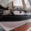
Finally it’s painted. Filler, sand, filler, sand and sand and sand, then paint, mask and more paint . . . finally. Well here it is.
Oh, yes. I still need to add that gold stripe.
Bob
-
captainbob reacted to Chuck Seiler in Gunboat PHILADELPHIA 1776 by Chuck Seiler - Scale 1:48 - from Model Shipways plans
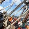
I flew some Sailors in to square away the lubberly rigging. Here is where I am as of now.
The swabbies thought the ladder rungs, in lieu of ratlines, were cute, so they left them on. Once I get the starboard gun installed, the rigging will go very fast. Once that is done, the forward railings and awning structure...as well as cats and dogs like anchors, rope coils, sweeps, etc.
I had taken several pics during our Guild meeting Wednesday, but all except this ended up being out of focus. More pics this weekend...if I can see thru the smoke and ash.
-
captainbob got a reaction from Elmer Cornish in Lettie G Howard by captainbob - FINISHED - 1:48 - POB - schooner
John I didn't measure mine either. Oh well.
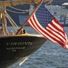
Lawrence, I am not that famiilar with the Annie M. Parker but In a quick look around on the web the schooner American Eagle at 97 feet and its plumb bow seems very similar.
Bob
-
captainbob got a reaction from JerseyCity Frankie in Lettie G Howard by captainbob - FINISHED - 1:48 - POB - schooner
Bedford, I don’t know why I ever doubt the force? It always comes through.
The planking is finished, the keel and the stern post are in place and the rail around the stern is on. There’s a lot of cleanup to do but the parts are there. Next its finish the rail and paint the hull and bulkheads, then the deck goes on.
Bob
-
-
captainbob got a reaction from JerseyCity Frankie in Lettie G Howard by captainbob - FINISHED - 1:48 - POB - schooner
First off I need to say thank you to all those who look in and click on the like button. It’s so nice to log on to MSW and see that red signal that says someone likes what you said or did. Again thank you.
Now to get on with the boat. The planking is almost done. A little more clean-up in the stern and mount the transom and keel. Also the planksheer so I can mount the stanchions and the bulwarks and then paint. Wow, I shouldn’t list things like that it makes it sound like a lot of work. Anyway here’s the pictures.
Bob
-
 captainbob got a reaction from Nirvana in J Boat Endeavour by fnkershner - Amati - 1:35
Yes, I used 91% isopropyl alcohol. The vodka was being used elsewhere.
Bob
-
 captainbob got a reaction from pete48 in Herreshoff Buzzards Bay 14' by pete48 - FINISHED - 3/4" = 1' - SMALL
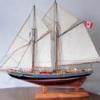
Ah yes, we're begining to see Herreshoff's beautiful lines come to life.
Bob