


wefalck
-
Posts
6,642 -
Joined
-
Last visited
Content Type
Profiles
Forums
Gallery
Events
Everything posted by wefalck
-

I made some shrouds for 1/450 Victory.
wefalck replied to modeller_masa's topic in Masting, rigging and sails
I was not aware of this and always had a good contact with him ... -
I made some shrouds for 1/450 Victory.
wefalck replied to modeller_masa's topic in Masting, rigging and sails
If you have access to pre-tinned copper wire, you could use this to good effect as Bob Wilson does. Check out his Blog, where he also various downloads and ebooks for sale: http://miniatureships.blogspot.com/ BTW, why does the rainy season prevent you from modelling ? Over here in Europe it would be just the opposite - or is it the high humidity plus high temperatures ? -
Beginning to look the thing ! As I said earlier, one should ascertain, whether the sails were furled underneath the spar or above it. The latter is probably associated with jack-stays, but I am not sure, that these were already used on the BOUNTY.
-
The problem, however, is that these dictionaries do not cater very well for the vernacular terms associated with lateen-rigged craft. When I wrote an article for NEPTUNIA (in French) and the LOGBUCH (in German) about a special kind of lateen-rigged craft from the Albufera-region south of Valencia/Spain, I had to compile for myself a special glossary in Valenciano/Catalan - Castillano (Spanish) - French - English-German. The terms in French and Catalan/Valenciano are quite similar, but the Castillano (Spanish) terms can be rather different. Another 'standard' dictionary is also PAASCH's 'From Keel to Truck', in its original edtion of 1885 comprising English, French and German. It was later enlarged to include also Spanish and Italian. However, it also not good on lateen-rigs. Not sure, whether there is a digital version of it. On the Net you can also find: ANONYM (1859): Dictionnaire universel théorique et pratique du commerce et de la navigation. Vol. I: A-G.- 1438 p., Paris (Guillaumin et Cie.). ANONYM (1861): Dictionnaire universel théorique et pratique du commerce et de la navigation. Vol. II: H-Z.- 1828 p., Paris (Guillaumin et Cie.). BONNEFOUX, P.-M.-J. DE, PÂRIS, E.F. (1859): Dictionnaire de Marine à Voiles et à Vapeur.- 2 Vols., 740+16 p., 17 pl., Paris (Artus Bertrand). Lorenzo, J. de, Murga, G. de, Ferreiro, M. (1865): Diccionario Marítimo Español, que además de us voces de navegación y maniobra en los buques de vela, contiene las equivalencias en Francés, Inglés y Italiano, y las mas usadas buques de vapor, formado con presencia de los majores datos publicados hasta el día.- 576 p., Madrid (Establecimiento Tipográfico De T. Fortanet). Reehorst, K.P. ter (1850): The Mariner's and Merchant's Polyglot Technical Dictonary. Upwards of Five Thousand Nautical, Steam, and Ship-Building Terms, Commercial and Scientific Expressions, in Ten Different Languages, English, Dutch, German, Danish, Swedish, French, Italian, Spanish, Portuguese and Russian, with a Precise Explanatory Key to the Pronunciation of These Languages, and a Comparative Table of the Money, Weights and Measures of Sea Ports.- 520 p., London (Williams and Norgate).
- 72 replies
-
- 3
-

-
- fishing boat
- Barco Catalan
- (and 1 more)
-
Yes, there is a thin line between an authentic worn look and a messy model, at least in the eyes of an unintiated beholder.
-
Personally, I would use a clear varnish or sanding filler (both organic solvent-based !) to stiffen the material - a dab of thinner allows you to re-arrange the sail even after the varnish has dried. CA or acrylics cannot be easily softened without destroying everything. Also at this small scale, real cloth is most likely too thick and coarse. For set sails the lightest silk-span might do, but for clewed-up or furled sails tissue paper is a better option. In the case of furled sails, you may also find that a full-size sail will result in too much sail on the yard, just shorten it a bit until the amount of sail looks right - this is because even tissue is way over-scale.
-
Are you trying to make furled sails or clewed-up sails ? Your 'attempt 3' shows actually a clewed up sail ... I would also check out how sails were 'bent' to the yards at that time, befor jackstays came into use. The thread you used seems to be a bit oversized for the purpose.
-
As I work only with small-scale models, I don't need a lot of paint. For this reason I use nowadays almost always acrylics pre-diluted for airbrushing. Per volume/pigment, of course, they are relatively expensive. I just take a dab of the acrylics in a small glass dish and add a drop or several of water. This then apply to the model and distribute it quickly with a wet brush. While the paint is still liquid, you can suck it up with a tissue. However, once the paint is dry, it becomes waterproof. This happens quite fast, so that one can apply the next wash quite quickly. One can, in principle, redissolve acrylics with acetone, but you may then attack all other layers of paint as well. So one has to do this with caution.
- 72 replies
-
- 1
-
-
- fishing boat
- Barco Catalan
- (and 1 more)
-
'Gallica' is the digital access system of the Bibliotthéque Nationale de France (BnF). There the link to the PDF is: https://gallica.bnf.fr/ark:/12148/bpt6k11684265.r=vence voile latin?rk=64378;0. Everything the BnF puts out is public domaine. I have a reprint, so I did not check before.
- 72 replies
-
- 2
-
-
- fishing boat
- Barco Catalan
- (and 1 more)
-
If I may, a couple of suggestions: - it's quite natural to have more dirt inside the difficult to clean areas around the bulwark - you could always touch up the white paint inside the bulwark - this would have been done on the prototype as well - I think the lettering sticks out a bit too much, it could be toned down with a washing of paint - I use very dilute washes of burnt umber acrylics for wheathering, in this way you can build up the right level quickly and safely At this scale you might want to fit a real sheave into the mast-top actually. Still probably the best source (albeit in French) on the lateen-rig and its use is VENCE, J. (1897): Construction & manœuvre des bateaux & embarcations à voilure latine.- 139 p., Paris (Augustin Challamel Editeur, reprint Editios Omega, Nice). Not sure, whether there is a digital copy floating around the Internet.
- 72 replies
-
- 2
-
-
- fishing boat
- Barco Catalan
- (and 1 more)
-
Framing, best materials
wefalck replied to Levmiller's topic in Building, Framing, Planking and plating a ships hull and deck
The concern about the visibility of the grain aside, it probably depends on the scale and type of the model and whether you are thinking of bent or sawn frames ... otherwise, what works for you on the practical side and what pleases you visually should be the guide. Perhaps from trials to test the workabiliy and how it looks with the desired finish would be sensible before embarking on full-scale parts production. -
Some people / navies like to have a rope-ring or something like this above the leathering to prevent the oar from slipping out of the thole. In other places this is frowned upon. I gather this is what Jerry was referring to ? Such a ring is usually a tight-fitting single or double 'Turk's Head' (well, today rubber rings are used). There are instructions for tying Turk's Heads on the Internet or in books on knots. At a 1/25 scale it should not be too difficult to replicate.
-
Framing, best materials
wefalck replied to Levmiller's topic in Building, Framing, Planking and plating a ships hull and deck
Difficult, if you are city-dweller in an appartment ... I once kept a branch from a cherry tree in my parents garden, but never found a way to have it cut up. -
This putty has some weird rheological properties. If you deform it slowly it act like a putty, when say form a ball and let it drop to the floor, it bounces off like a rubber ball, but when you hit it with a hammer, it crumbles away. Perhaps, when you try to pry it out of crevices with some instrument it thinks it has to become stiff and doesn't move ... I think, I would have gone for some low-tack modeller's masking tape, such as that sold by Tamiya. Anyway, she comes along nicely !
- 72 replies
-
- 1
-
-
- fishing boat
- Barco Catalan
- (and 1 more)
-
These kinds of weathering techniques are not often seen in our realm ...
- 72 replies
-
- 1
-
-
- fishing boat
- Barco Catalan
- (and 1 more)
-
Actually, I think you would need one cleat only, one on the mast to belay the halliard for the sail. But not even that may be needed, as one could tie the halliard simply to the bench. Sheets on small boats are never belayed, so that you can let it go immediately in an emergency. However, a half-cleat on each side, or something like that, might be useful to lead the sheet around and ease the strain somewhat. There is no information on how it was done on the real thing ?
-
Ah, these stupid SSL-certificates are playing up again, when I am linking to my own Web-site. I directly uploaded now the image. Thanks for letting me know, Eberhard
-
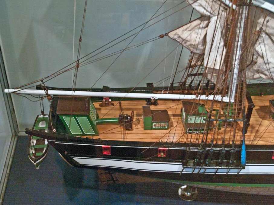
The snow-rig seems to have fallen out of fashion around the middle of the 19th century and its prevalence seems to have been unevenly distributed across the European regions and North America. One reason, why one does not see many old models of snows is perhaps, that this is a rig largely associated with smaller merchantmen and not too many models of them were built at the time or have survived. On ship portraits, however, it is quite frequent. Here is an interesting arrangement on the snow ELISABETH (1839) of Altona (Hamburg). The model was built in around 1900 from old plans by shipwrights and rigged by real riggers etc. The snow-mast is actually stepped on the gaff and not on the deck ! More pictures from this model in the Altona-Museum here: https://www.maritima-et-mechanika.org/maritime/hamburg/altona.html
-
Doesn't it lift off the paint ? Or may be not, as it is supposed to be made from some kind of silicone.
- 72 replies
-
- 1
-
-
- fishing boat
- Barco Catalan
- (and 1 more)
-
Apropos the rudder: it had to be capable to be unshipped very quickly when the boats where beached, particularly, when there is any degree of surf. As the rudder extends below the keel, you would hit the sand and either damage the pintles or it might become unshipped by itself and lost. At many of the shallow coastlines from which these boats would (have) operate(d) there is a shallow sand bar about 50 m from the actual beach that may have only a foot or so of water on it. You wouldn't be able to pass the bar with the rudder shipped. Another reason is that the incoming surf would hit the rudder and swing the boat around so that its broadside would be hit by the waves - a dangerous situation ... Haven't seen magic putty for more than 50 years. Didn't know it still existed and that modellers use it to mask for spray-painting. May have to look into getting some.
- 72 replies
-
- 2
-
-
- fishing boat
- Barco Catalan
- (and 1 more)
-
Modelling locks or Latches
wefalck replied to jackieofalltrades's topic in Metal Work, Soldering and Metal Fittings
Actually, the good old door locks, whether set into a mortice or screwed to the inside of the door are not too complicated. I found an image on the German Wikipedia that shows the inards (and the one or two locks that I took apart looked very similar indeed): The square hole on the top is the one for the door knob or handle. C is the template for the key - in this kind of lock the bolt can be moved with any hook that fits through the template, i.e. they are easy to pick. The key is inserted with the nose down, when you turn it up, it moved the notched bolt to the right and lifts it against the spring (b) loaded latch. You can turn the key twice, moving the bolt deeper into the mortice in the door-frame. The manual bolt (d) is not normally available in locks fitted into the door. For a lock terminology have a look here: https://www.timpsonlocksmiths.co.uk/locksmith-terminology/ I don't think it would be too difficult to reproduce a simple working lock as per above sketch in 1/12 scale. It would be probably about 12 mm high, 10 mm wide and 3 mm thick. The body would be two plates held apart by studs. You may probably get away without the springs, or make a simplified arrangement. -
CA smudges
wefalck replied to gardbla's topic in Painting, finishing and weathering products and techniques
It all depends on the materials used. Perhaps the safest way would be to rub down the affected areas with steel wool and apply more varnish to blend the area in with the rest. -
Modelling locks or Latches
wefalck replied to jackieofalltrades's topic in Metal Work, Soldering and Metal Fittings
Not sure, I understand the problem well. There are three basic types of locks: - the kind of box that is screwed to the inside of a door and the latch runs into a U-shaped part that is screwed to the door-frame - my father used to call this cow-shed lock - the traditional style, where the box-shaped lock slides into a mortice in the door and is screwed down to the narrow side of the door, for which purpose the box has longer flat piece of metal attached to its narrow side; the latch runs into mortice in the frame that is re-enforced with a metal plate - the zylindrical security locks that a set into a bore of the door and the latch runs again into a mortice in the door frame. So what do you actually want to model ? The whole lock with its mechanism ? -
Gentlemen, Thank you very much for your kind words and praise ! I think that not scale is the problem, but rather the limitations are due to materials availability, its workability and perhaps also skill, but certainly patience. If I was working at, say, a scale of 1/48, I would want to put roughly three times the amount of details in - which then would also take roughly three times as long. On the gun there were a lot more details that I could have added, based on the available information, but it was physically (at least for me) not possible. For me the material really is the limitation, there are vitually no wires of less than 0.05 mm diameter, and if so, they would be physically almost impossible to work with. I have drills down to 0.1 mm diameter, but drilling holes with less than 0.3 mm diameter is, depending on the material, a real challenge. I can turn short stubs down to 0.1 mm, but it is very difficult to make longer parts with less than 0.3 mm diameter in steel, let alone in the much softer brass. For such operations one would need much bigger machines with well-balanced, vibration-free spindels etc. The next update will look into ammunition for the gun and its handling ...