wefalck
-
Posts
6,648 -
Joined
-
Last visited
Content Type
Profiles
Forums
Gallery
Events
Everything posted by wefalck
-
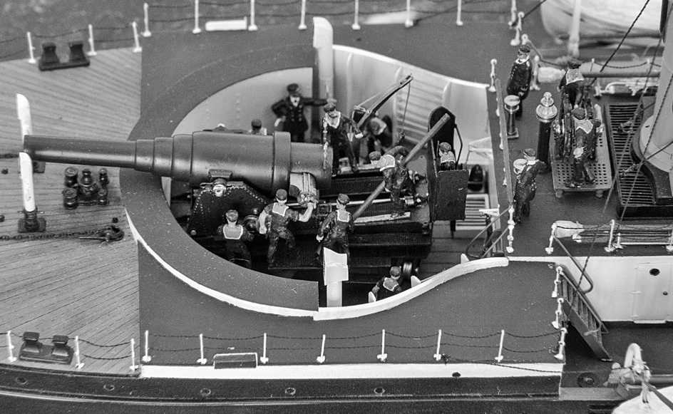
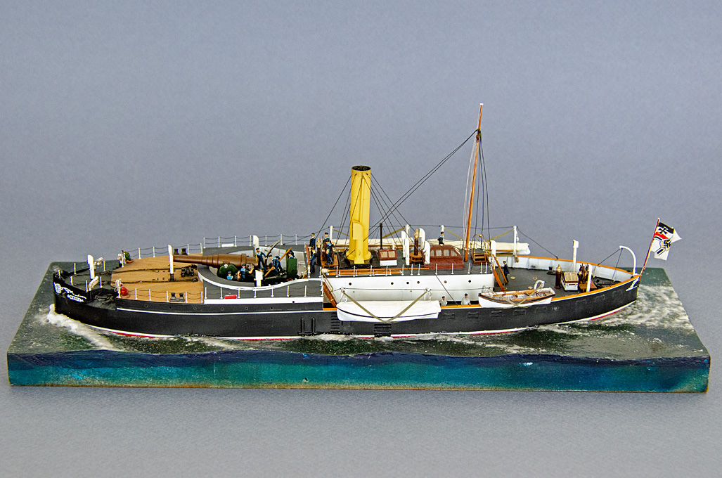
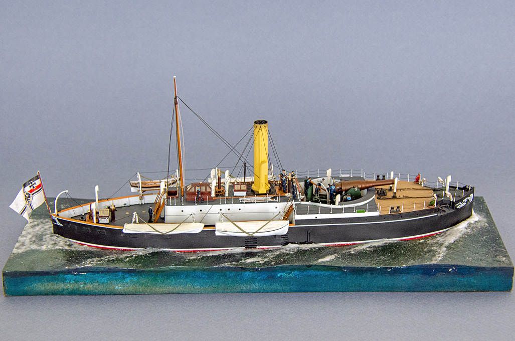
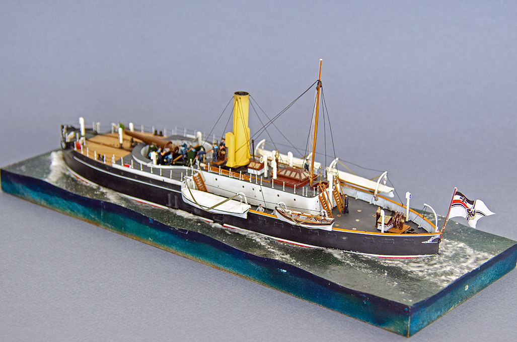
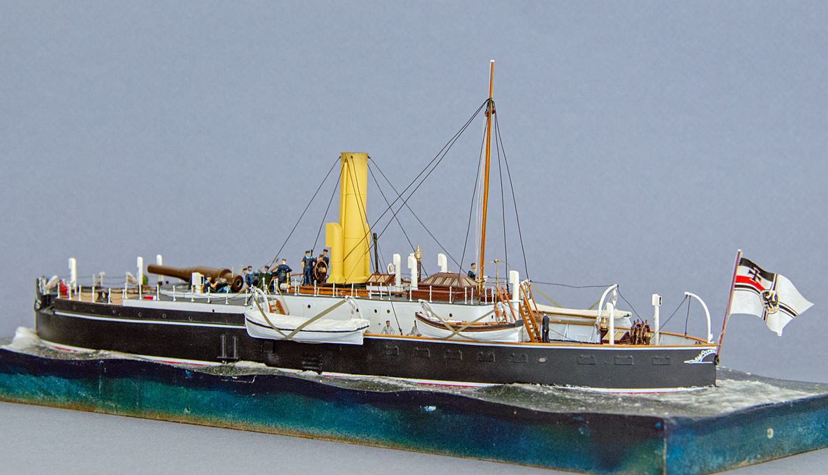
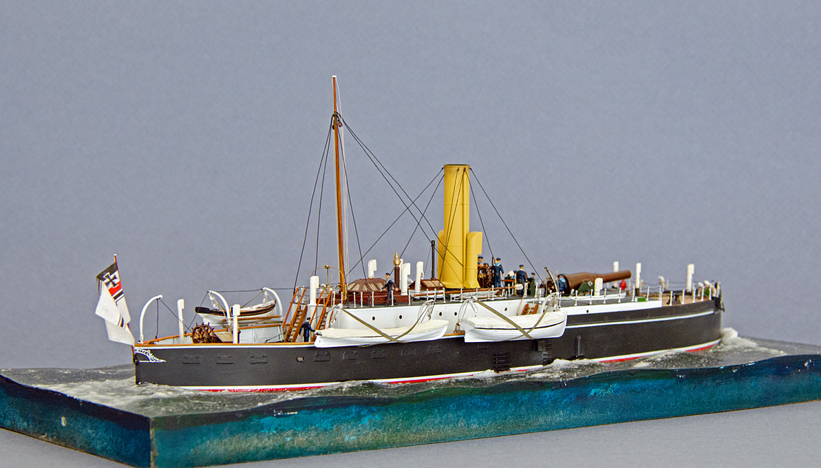
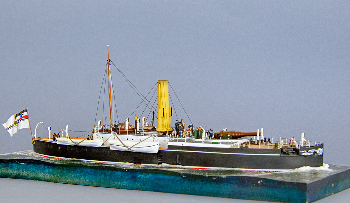
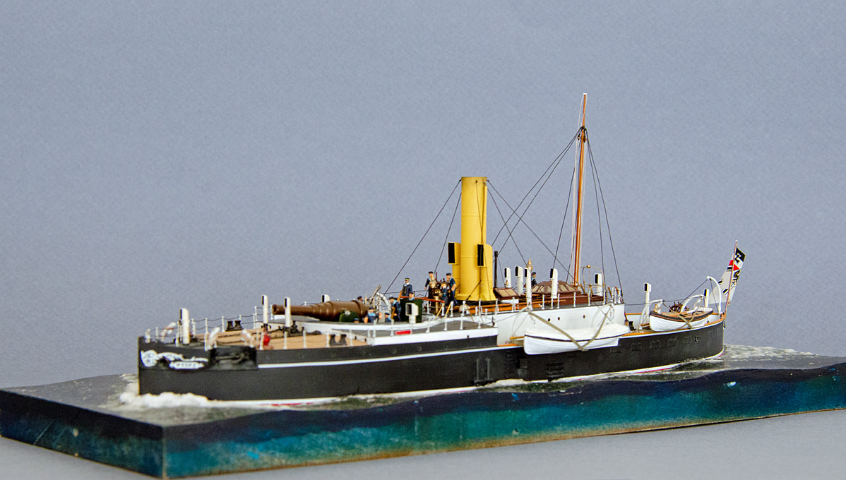
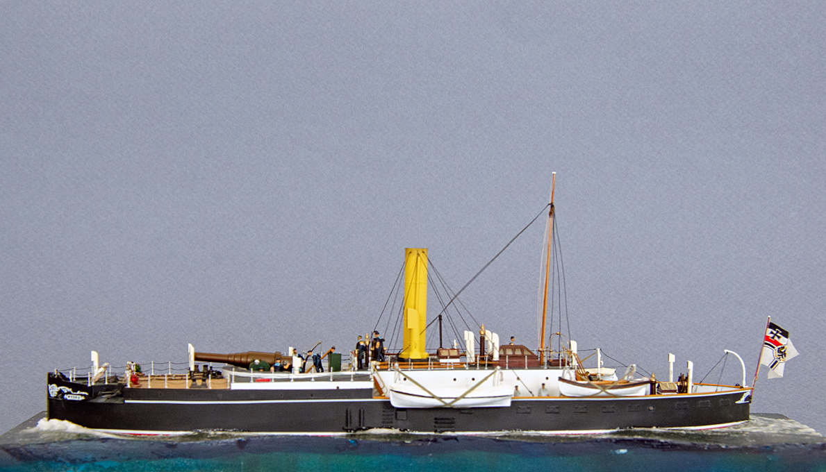
 A few glamour-shots of S.M.S. WESPE Finally, I managed to go into town to buy a suitable paper as backdrop for the glamour-shots of the whole model. Here they are without further comments: And also two shots in black & white:
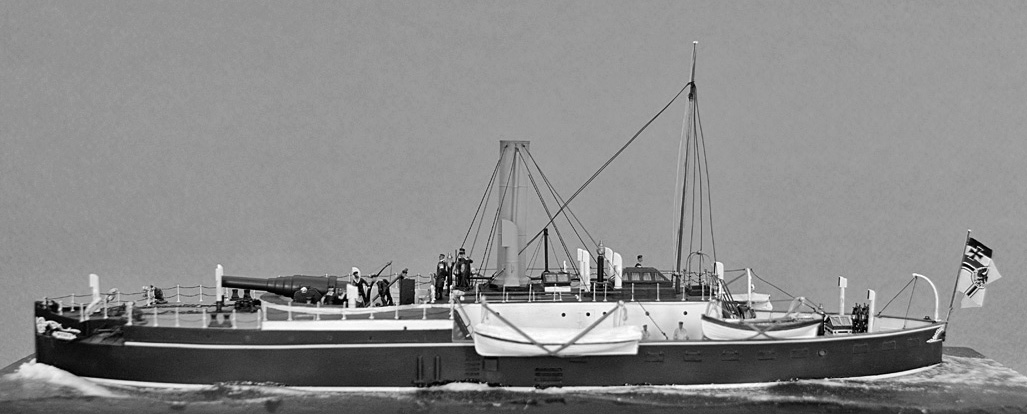

- 935 replies
-
- 21
-

-

-

-
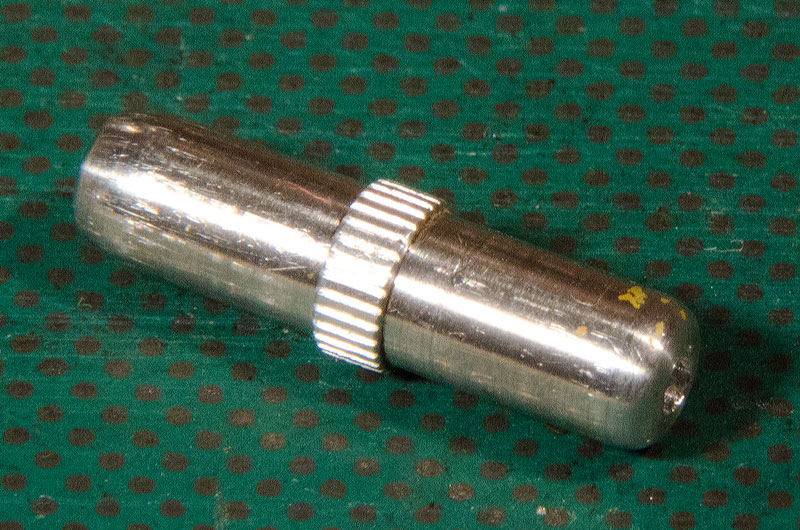
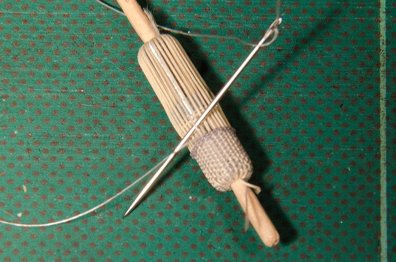
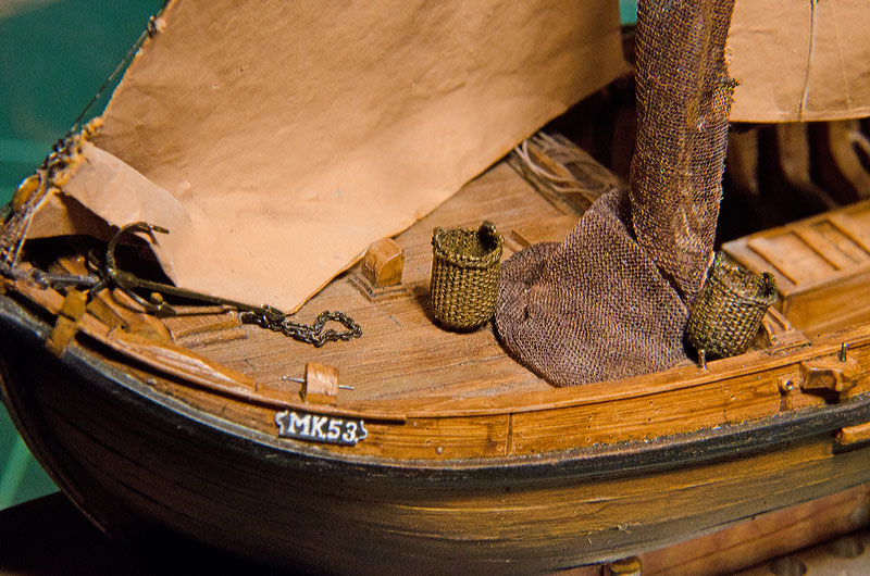
I gather in some cultures they make 'sewn' baskets from coiled-up braided strands of whatever fibres are available. Each layer of the coil is sewn to the one below. Otherwise, I can offer a high-tech solution that might be adapted to the availability of tools: For the Botter-model I needed a couple of fish-baskets and I decided to weave real baskets, well almost. For this I needed a tool that would give the basket its shape and allow me to handle it while weaving. So I turned the little implement below from a piece of 5 mm diameter aluminium and drilled a 2 mm hole all the way through it. It will allow me make two baskets simultaneously. The material for weaving is another issue. I would have like to use wire, but it would have been difficult to actually weave with wire. So I used some thin cotton thread for the stakes and fly-tying yarn for the weave. First the ‚stakes’ were put into place by winding the thread around the form tool in a continuous series of loops, passing the return part through the middle of the center bore of the tool. This then was woven out with the fly-tying yarn using a sewing needle. The rim is a bit of a fake: normally the stakes would be bent back one over each other to produce a stable and decorative finishing. Here I made a double row of half-hitches with the weave, i.e. the fly-tying thread. Once this was finished, the ‚basket’ was soaked in wood stain and then a few dabs of matt varnish were applied to secure the weaving. The stakes with the exception of two on each side then were cut off flush with the rim. The remaining stakes were twisted into looped handles. Finally the stakes were cut around the hole in the bottom of tool. A bottom of the basket was faked by closing the hole with a good drop of white glue. The baskets then were weathered using acrylics paint (umbra). I am sure that this technique can be easily adapted to a larger scale. You were already half-way there ...
-
That came out pretty neat 👍🏻 Do they drill holes through the stones(?) used as weights, or do they strap them on? For the latter option you could find some small stones and tie a thread around them as if you would tie up a parcel. The loose ends you then can knot into your net. Alternatively, you could try to get hold of some shredded cork. Not sure, whether in your part of the world there are any model-railway shops, but if so, they may sell shredded cork in different size grades. If not, you may need to empty a couple of bottles and shred the cork yourself. The cork-rocks can be easily drilled (if that is the method of attachment) and painted up to resemble rocks.
-
Impeccable metalwork as usual 👍🏻 However, somehow I don't see the the two chain-wheels, that should have depressions for the chain-links ...
-
... the same was probably said, when manual lathes and milling machines and powered saws were introduced. The question is: what is our objective - to build better models or to develop manual skills? On the other hand, if you want to show bare metal or wood, there is no 3D-printing option (yet).
-
In case you are not happy with the way the net turns out, other materials to consider would be ladies' stocking or pantyhoses. You may need to look for 'patterned' ones for larger mesh sizes. They can be staked out on a board to stretch the meshes and then ligthly sprayed with varnish to keep the meshes open, but not so much soaked as to make them too stiff. If your wife doesn't wear a suitable colour, the material can also by dyed. I have used this method for a 'tanned' net, albeit at a much smaller scale (1/90):
-
Just to mention and without wanting to imply anything, in the past I have simulated such pipe insulation with twisted strands of asbestos wool by winding cotton thread around the wire and soaking it in varnish:
- 128 replies
-
- 7
-
-
- zulu
- sternwheeler
- (and 1 more)
-
Not sure that the inhabitants would have appreciated this ... wasn't the boat operating in a tropical climate?
- 128 replies
-
- 3
-
-
- zulu
- sternwheeler
- (and 1 more)
-
Relatively? May be you are still think of thinning the leading edges? What ever the conclusion, it it a nice piece of metal-workmanship 👍🏻 I actually wondered, whether the five-bladed propeller was a more recent addition to the boat? I would think that the original arrangement would have included a three- or four-bladed one?
-
Aren’t many of such titles now available as free digitalisations?
-
Ancient galley rams discovered - photos
wefalck replied to Louie da fly's topic in Nautical/Naval History
I seem to remember that the Roman ships were more heavily built than the Punic ones (or the earlier Greek ones in any case), as the Romans were not a seafaring nation at all and wanted to transfer their land-battle tactics to the sea. Hence they manned their ships heavily with soldiers, fitted them with a sort of drawbridge to grab enemy ships and deploy those soldiers in hand-to-hand fighting. This probably means more ballast to keep the ships stable. Also, I believe, the Roman ships were rowed by slaves, who were kept on board at all times, so that infrastructure for sustaining them was needed. Not sure about the Punic ships. The Greek ships were rowed by free citizens of the respective communities and typically disembarked in the evening, as the ships would be pulled up on the beaches. Greek tactics mainly aimed for ramming the enemy ships or at least break their oars. Very few extra soldiers were on board. These tactical requirements would have resulted in comparatively light ships only. -
Ancient galley rams discovered - photos
wefalck replied to Louie da fly's topic in Nautical/Naval History
I have been to the Hellenic Maritime Museum in Piraeus/Athens a couple of days ago. And there, on the room dedicated to the ancient Greek warships, it was noted that the captains of a trireme etc. were obliged to salvage the ram in case their ship went down. It was also noted that the construction of the galleys would mean that they float on the wood and not sink, once pierced, which would explain, why no rams so far have been found at the sites of major seabattles, such as Salamis. Obviously, this did not apply to Roman or Punic ships. -
Yes, but these are secondary sources with specific temporal and/or regional focus. One should not forget this.
-
Thanks, I was aware of this work. Interestingly, their terminology differs in places from the one used in maritime circles - but this is rather a discussion for a German forum (where we already had it, I think).
-
I have put together a lis of published literature specifically on masting and rigging. There are some more titles in addition to those already mentioned: https://www.maritima-et-mechanika.org/maritime/maritimebibliographies/masting&rigging-bibliography.pdf Those marked with 'E' are available in digitised form, but you would need to look for yourself for a link.
-
When I serve splices etc. I start with either a clove-hitch or an overhand-knot and continue with half-hitches. The half-hitches make sure that the turns stay tight on the served area. To secure knots, splices and servings I use a fast-drying varnish, similar to nail-varnish, but the old, solvent-based variety, not the modern acrylic ones. In this way, everything can be loosened, should the need arise.
-
Yes, alloys can be deposited galvanically. It’s regularly done for objects such as furniture or lamp fitting. The electrode should be brass of the copper to zinc ratio that you want on the final product, which determines the colour, ranging from reddish (high Cu) to yellowish (high Zn).
-
Floor and frame spacing
wefalck replied to BANYAN's topic in Building, Framing, Planking and plating a ships hull and deck
I gather areas, were the load would be high, e.g. from the pivoting and firing guns, could have closer spaced frames, dito., where boilers and machinery are located. In the bow, the cant-frames are spaced closer to better take up the stresses from diving into the sea. On the other hand, uneven frame spacing would also cause uneven stress distribution along the hull, with some areas being stiffer than others. This should lead to higher stress on wales, stringers and the hull-planking in these areas. By then the spacing is already quite close, so that there may not be a quantitatively significant effect. When you say 'bent' frames, you mean they really steam-bent such big timbers, as you would in boat-building? -
A sort of transition solution between the ruling pen and the modern Rotring etc. lining pens was something that is called a 'funnel pen' (not sure my translation from German 'Trichterfeder' is correct). This is essentially a tiny funnel with a capillary at the end of defined diameter (to conform with the standardised line widths in technical drawings). A thin wire runs in the capillary to regulate flow and keep it clean. They are still used in porcelain-decoration for applying gold suspensions. I inherited a couple from my mother's hobby kit and have one or two antique ones I think. The problem is that they may clog up quickly when used with paints, as they are meant of use with inks. In principle they are easier to use then the old-style ruling pens.
-
It this seems that a lot of table-ware was made from silver-plated Britannia metal in the old days. So it may be worthwhile looking for Internet-resources on restoring such pieces. Otherwise, jewel-makers use a lot of electroplating and 'tampon-plating' (meaning the electrolyte is held in a wet piece of felt with which the workpiece is touched, rather than immersing it in the electrolyte) for repair purposes. The respective supply houses offer hand-held kits for that purpose.
-
Floor and frame spacing
wefalck replied to BANYAN's topic in Building, Framing, Planking and plating a ships hull and deck
My sound like a stupid question, but have you consulted any shipbuilding textbooks of that time? There is a variety of English language mid-19th century texbooks available on the Web. -
"Step 6 was to create a tool to cut the slots. I had decided on a slot width of .040" and I ground a single point milling tool and machined a tool holder to facilitate the cutting of this width." I was wondering, why you didn't use just a slitting saw? Maybe you didn't have one of the right thickness and diametre?
-
Ah, I understand now. This is tea-bag paper sold in sheets for use by artists. This paper is obviously not disintegrating quickly when wet, which has advantages in our case. Perhaps we should stop using the term 'silkspan' because it refers to different materials in different countries and originally was a marketing term. The best way to talk about such materials would be to refer to their weight per sqm or sqft, to the kind of raw-material used, and whether it is a fabric (i.e. woven) or paper (i.e. more or less short fibres arranged in an irregular fashion). The lightest and, hence, thinnest paper I was able to source in France comes from Japan and weighs 8 g/sqm.
-
What are 'artists' tea bags? Some teas are sold in a kind screen-printing fabric-bags. Screen-printing fabrics come an a wide variety of thread thicknesses and 'meshes' and can be easily obtain via the usual routes, e.g. ebay et al. I have used this kind of fabric sources from tea-bags to simulate metal grilles in small scale (1/160). It was easier to work with than the comparable metal fabrics used in sieves.
-
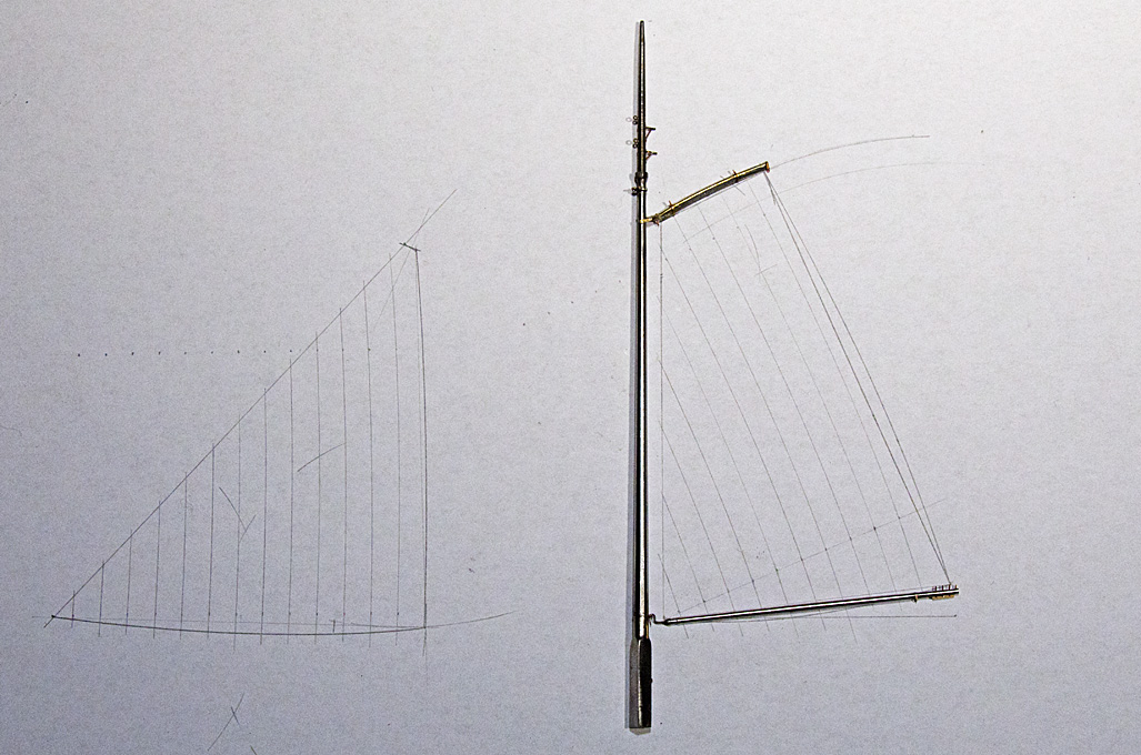
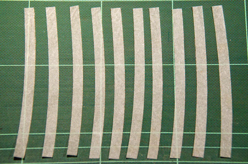
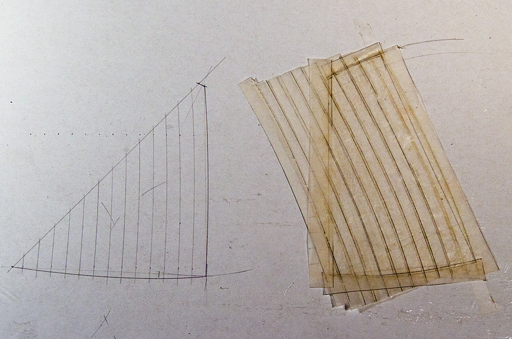
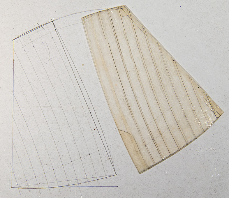
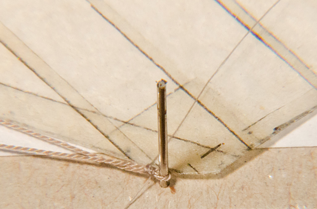
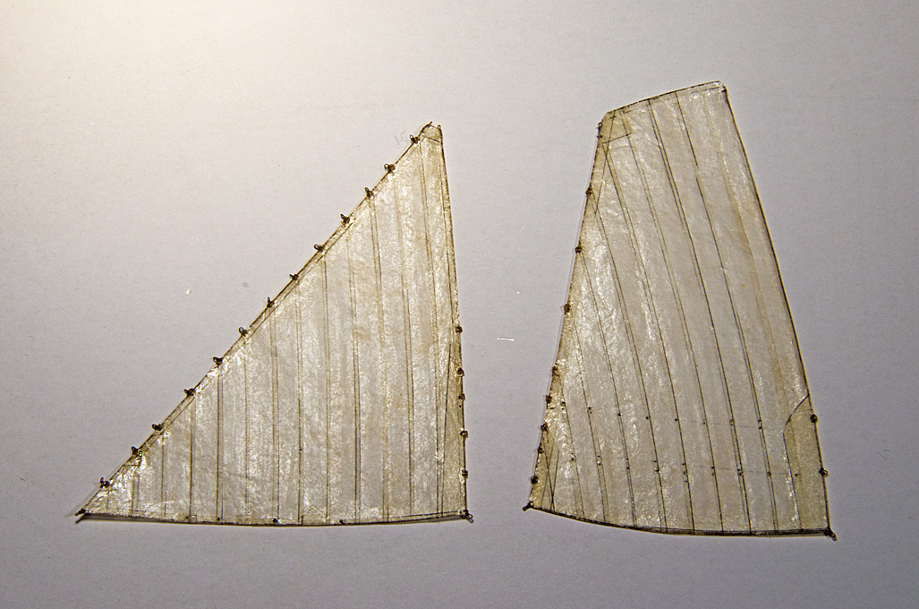
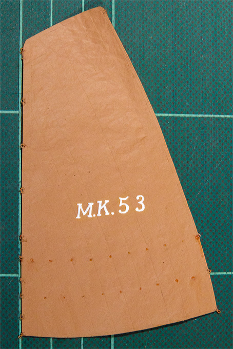
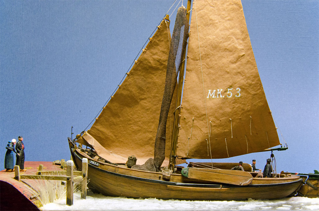
I have used silk-paper and silk-fabric (as used to 'span' model aircraft wings etc.) for decades. The first time I made the sails up from individual panels was in the mid to late 1990s, I think. Below is the sequence for making some 'tanned' sails in 1:90 scale. Because the prototype sails were tanned with a mixture of tallow and ochre, I was not concerned about translucence: A computer drawing (above) from which the individual panels were separated was taped to a board onto which the silk-paper was taped. The panels were then drawn onto the silk-paper and cut out with an allowance for the seams: The original computer drawing was then taped to a board and covered in clingfilm. Onto this the first panel was taped and painted with a fast-drying varnish. The next panel was treated in the same way and so forth. Then doublings etc were added and when complete the sail was removed and trimmed to size: After this step the sail was returned to the clingfilm-covered drawing and lightly taped down so that the boltropes could be glued on: Also cringles and other ropework was added: In the final step, the sail was spray-painted to simulate the tanning: This method works very well for set sails, but for gathered up sails and so on, there is risk that the glued seams open and also the various coats of varnish and paint make the rather stiff. Therefore, for my next project, where the untreated flax/hemp sails will be hanging limp for drying over stays and spars, I might try the method suggested by druxey. The lining pens druxey uses were a standard feature of technical drawing sets. I got my drawing set when entering secondary school in 1967 and still have it. I remember trying to use it with enamels during my teenage years but that didn't work very well. I can imagine that with acrylics pre-diluted for spray-painting (e.g. my favourite Vallejo ModelAir) it will work very well.