


wefalck
-
Posts
6,648 -
Joined
-
Last visited
Content Type
Profiles
Forums
Gallery
Events
Everything posted by wefalck
-
 Many of the earlier Spanish railway coaches had a definitely American feel to them and they retained wooden panelling for the body much longer than in other parts of Europe, perhaps indeed because it insulated better against the heat than sheet metal. Catalunya (for the time being) is still part of Spain, although the current Spanish president seems to have bought his second term in office by paving the way for them slipping slowly away. Talking about 'nationalist' tendencies in Spain: then one should also say 'Alicant' (in Valenciano) and not 'Alicante' (in Castellano).
 -
Double stress: getting it right and that your wife might come home early, finding out what tools you used 😱
-
Milk delivery wagon by RGL - FINISHED - Miniart - 1/35
wefalck replied to RGL's topic in Non-ship/categorised builds
... just remembered that I still have a 1:87 scale model of a Tempo flat-bed lorry from the early 1960s made by Wiking. Wiking originally made naval and aircraft recognition models, but then after the war started to make those 1:1250 scale shipmodels, first die-cast and then in styrene. And they branched out into model cars in the mid 1950s or so. They became the quality standard for decades and now are collectors' items. My oldest are from around 1959. -
Milk delivery wagon by RGL - FINISHED - Miniart - 1/35
wefalck replied to RGL's topic in Non-ship/categorised builds
They used to be common in Germany, when I was a little boy. Our greengrocer had one (the 'pick-up' version, as one would probably call it in the USA). They had a distinctive sound, due to the two-stroke engine. -
Zapon varnish is what I actually use. I gather it depends on the kind of paper one uses. Bonded and/or filled (with kaolin or another clay), such as Bristol-board, probably doesn't work in that case. I use highly calandered, but not bonded paper (sold in France and Germany as 'Canson' paper). Sanding filler (in Germany: Schnellschleifgrund, e.g. from Clou) also works.
-
If you soak the block-blanks in a fast-drying varnish, you will be able to lightly sand it to shape with a very fine diamond (nail) file. I would soak the blanks for the cheeks and sheave in varnish and then press them together. Once the varnish is dry, you can sand the block into shape. You then can finish the block in the way you described.
-
According to my calculations Alterfil L400 should have a diameter of around 0.06 mm.
-
Ooops, I almost responded in German 😁 That looks like a good start. What's the diameter of the 'rope'? Perhaps you could use a fake splice ('Bändselspleiß') in German instead of knots. They are quite easy to make with the help of a hypodermic needle as marlinspike.
-
Unfortunately, I don't have access to my library at the moment and cannot look up the pages. However, there is a section on rigging, where he describes, how he makes the oval punches, there is a picture that shows him whacking away, punching out the discs, and there are a couple more pictures, where he assembles a double boom-sheet. He uses a similar method for the deadeyes, but cheats a bit in the sense that he runs the shroud along the whole length and the deadeye/lanyard arrangement is kind of fake and glued to the front and back of the shroud. I don't think he wrote another book, so we are talking about this one, I suppose: MCCAFFERY, L. (1988): Ships in Miniature.- 144 S., London (Conway).
-
I may be mistaken, but I think Focke-Wulf built only all-metal aircraft, no fabric panels ... There are various German-language resources on the Fw200 on the Internet, that should be accessible with the aid of GoogleTranslation: https://de.wikipedia.org/wiki/Focke-Wulf_Fw_200 https://fw200-restaurierung-bremen.de and https://www.google.com/search?client=safari&rls=en&q=FW200&ie=UTF-8&oe=UTF-8
-
McCaffery actually describes quite in detail, how he makes (or perhaps simulates) blocks. In fact, he assembles the tackles made from twisted wire and then sticks paper discs onto the places, where the blocks are. The hitch is that he makes his own oval punches, which requires drilling and filing of silver-steel rods, which then have to be hardened and quenched. I have tried a similar method for 1:160 scale, using 'real' rope and laser-cut paper-discs, but the result was not very satisfactory. I think McCaffery's method with wire might be the best option at 1:300 scale. In my experience, twisting more than two wires together does not really work, unless you can really ensure that the pull on each wire is absolutely equal. Unlike for 'rope' the individual 'strands' (i.e. wires) cannot move against each other to give you a smooth rope. If you twist the wires tight enough, it is not easy to see, that there are only two wires.
-
Rather than boat-hooks (because they actually do not have hooks at the end) I think these are poles for 'poling' the boat along canals or to push it across shoals (of which are a lot in the Zuiderzee and the tidal waters around). The fork at the end would suggest this. Such poles can still be found on Dutch craft.
- 40 replies
-
- 3
-

-
- Speeljacht
- Card
- (and 3 more)
-
Cute little model she is and well done 👍🏻 When you referred to 'pencil work', did you mean shading with a pencil around details?
-
Not sure, how this was done on a 'speeljacht', but usually, there was a solid block of wood (in German: Schwertpoller), a bollard, through which a heavy pin ran ('Schwertnagel') on which the lee-boards pivoted. On later boats/ships there was an iron frame going over the bollard, which held the pin. The side-views that you showed, don't show the bollard above the rail, so it may be inboard. However, a solid piece of wood would be needed to hold the lee-board. There is also a lift attached to the lower edge of the lee-board, that allowed to raise it above the water. The lift was belayed on another bollard or cleat inboard. In order to get a clean line along the waterline, you could use white decal sheet. Cut a thin stripe and apply it along the the desired line. With acrylics you can paint over it to almost touch the edge. The acrylic paint will also cover up the lower edge of the decal strip. I also tend to play with different grades of glossiness/mattnes. Some people like their small-scall models all matt, but I think the different grades enhance the appearance of different materials or surface treatments. At this scale, the project is going to be quite a challenge and I will follow with interest.
- 40 replies
-
- 1
-
-
- Speeljacht
- Card
- (and 3 more)
-
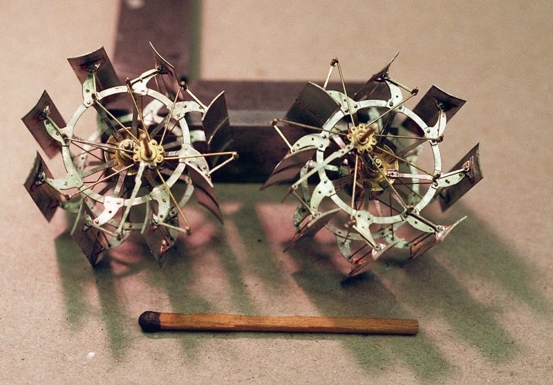
There is a 90+ year old gentleman in Munich, who is really an artist in metal-work. The parts for the wheel are photo-etched.
- 128 replies
-
- 6
-

-

-
-
- zulu
- sternwheeler
- (and 1 more)
-
How is the hammer released on those pile-drivers? I seem to remember that (at least on the ones over here in Europe) there is a sort of tripping mechanism, that releases the hammer (in German we call it 'ramming bear'), which then drops down in free-fall. The halliard then is lowered and clicks automatically into the hammer.
-
Apart from the fact that it may have been knocking about in your workshop, but why did you use plywood? Plywood, of course. is designed to resist curving in two directions ...
-
Just out of curiosity: is this actually a real fire-engine harness? They used to have special harnesses that were suspended from the ceiling in the fire-station and could be sort of just dropped onto the horses that were taken from the stables and reared up against the engine. I think they were able to get the engine on its way in a couple of minutes or so. Most horse-drawn fire-engines I have seen were designed for a single team of horses. This makes a lot of sense, because it is quicker to get under way and more manoeuverable on the streets. Perhaps the situation in the USA was different with longer distances to cover in the cities and wider streets. There is a short video on Youtube that shows a complete Paris firefighting team on its way to a fire: Sorry, I didn't want to drift away the thread from its real topic ...
-
Similar boats were still built by the 'Marsh Arabs' in southern Iraq in the middle of the 20th century I think (see Wilfred Thesingers book on the 'Marsh Arabs').
-
I would think that the steam-plant and the machinery would provide sufficient counterbalance? Unlike for a crane, the load and the distance of the load from the barge does not change so much on a pile-driver.
-
Shellac + Bitumen
wefalck replied to Loracs's topic in Painting, finishing and weathering products and techniques
It really depends on the purpose and what kind of effect you try to achieve. Any of them can work. However, I am not sure about bitumen on a model … the same effect can be achieved with dyes or washes of paint. -
Artists pastels are good for such weathering. White, grey, black and some olive green for around the water-line. The originals would have treated with a solution of tar, but your wood resembles already that.
-
Fixing one end (with hoops) and then the other is indeed full-scale practice in barrel-making.
-
Joining in into the chorus! Any crew or passengers foreseen? There should HO-scale figures suitable for conversion, if needed.
-
Soldering is joining two pieces of metal with the aid of another metal that has a melting point well below that of the pieces to be joined. Welding is heating (punctually) the two pieces of metal (or plastics) to be joined up to their melting point and then pressing them together.
