
HOLIDAY DONATION DRIVE - SUPPORT MSW - DO YOUR PART TO KEEP THIS GREAT FORUM GOING!
×


wefalck
-
Posts
6,546 -
Joined
-
Last visited
Content Type
Profiles
Forums
Gallery
Events
Everything posted by wefalck
-
 No, not for gem-stones, but you are right, these have a similar 'goniometer-head'. The Deckel SO is a tool-grinder for single-lip tools, such as D-bits, engraving cutters, and can be also used for chisels. The tool can be turned around its axis at a given angle to the grinding wheel, which is needed for hollow gauges.
 -
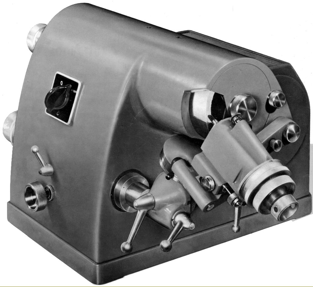
Ideally, one should have something like the Deckel SO (or one of the various old or modern clones), perhaps with a diamond honing wheel, for sharpening: Image from http://www.lathes.co.uk/deckel/page3.html To make the gauges one probably needs something more complex, with knife-edge grinding wheel. Or one starts from silver-steel/drill rod, drills a hole on a lathe and then grinds away the rest. This then needs to be properly hardened and tempered. Not sure, how V-gauges are made.
-
Miniature Russian carving tools
wefalck replied to druxey's topic in Modeling tools and Workshop Equipment
... and one shouldn't anyway now. In principle, anyone with a good tool-grinder could make such tools from round HSS-blanks. -
OUTSTANDING Mini Drill
wefalck replied to Bill Jackson's topic in Modeling tools and Workshop Equipment
Looks like the thingy that was given to me by my wife with good intentions, but I found the speed too high for most practical purposes. Mine has three speed settings, but it starts from the highest and then steps down. With all battery-operated equipment it has the disadvantage that one cannot start and stop it free-hand, i.e. with a foot-switch ... Do the inserts have the usual 2.34 mm diameter shaft? -
It should be possible to find someone with EDM (Electrical Discharge Maschining) capability to make such dies from hardened steel in a small series ...
-
In my experience, acrylics are better applied by airbrush. Somehow, the self-levelling is not as good as for organic solvent-based paints. They also dry too fast to be able to equalise them well. Or may be, I am not that good a painter ...
-
I am still pondering the kit. I wouldn't build in WD-finish, but rather as a normal road-locomotive. The WD specifications (for good reasons) seems to have included unusual combinations of features, such a dished fly-wheel (as for road-locomotives, to not frighten horses on the roads) and wheels as for agricultural engines.
-
Already put together ... I had hoped for step-by-step assembly pictures ... 🥲
-
I you go that down that road, you should at least scrape/sand off this complete unrealistic woodgraining that these kit manufacturers seem to be so fond of. Afterwards, you may need to (re-) engrave lightly(!) the plank seams.
-
Everything you need to know about gondole and other Venetian boats: https://www.veniceboats.com. Gilberto Penzo also has a little shop in Venice, where he sells his books, the plans and the kits he has designed.
-
Proxxon mini lathe verdict
wefalck replied to Srenner's topic in Modeling tools and Workshop Equipment
Are the collets really made from plastic? I am shocked, as PROXXON has been priding themselves rightly for their metal collets on other machines. -
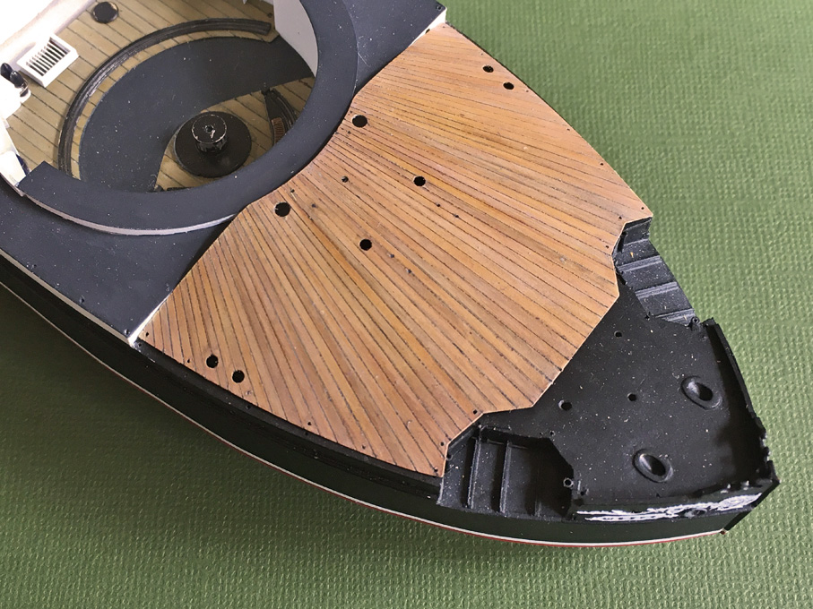
Well, at 1/96 scale most woods would have really a too coarse grain, particularly those commercial decks made from veneer. Unlike wooden shipmodels, where the builder may want to show his woodworking etc. skills, plastic models usually are finished to show how the ship (may have) appeared in real life. Mixing visible wood with plastic may look incongruent in style. My personal choice would be to replace the injection moulded deck with some styrene, lightly engrave the plank seams, lightly scrape down any raised burrs, and build up the coamings etc. from styrene strips. Then paint the deck in wood colour (I use these days mainly Vallejo acrylics), seal this paint with gloss varnish, take a black 0.1 mm felt-tip pen and draw out the seams, wiping off any excess immediately, so that the black only stays in the engraved lines. Seal again with satin varnish and then slightly tint each individual plank with veery light washes of burnt umber. Afterwards apply a very light white wash all over. The result should look like this:
-
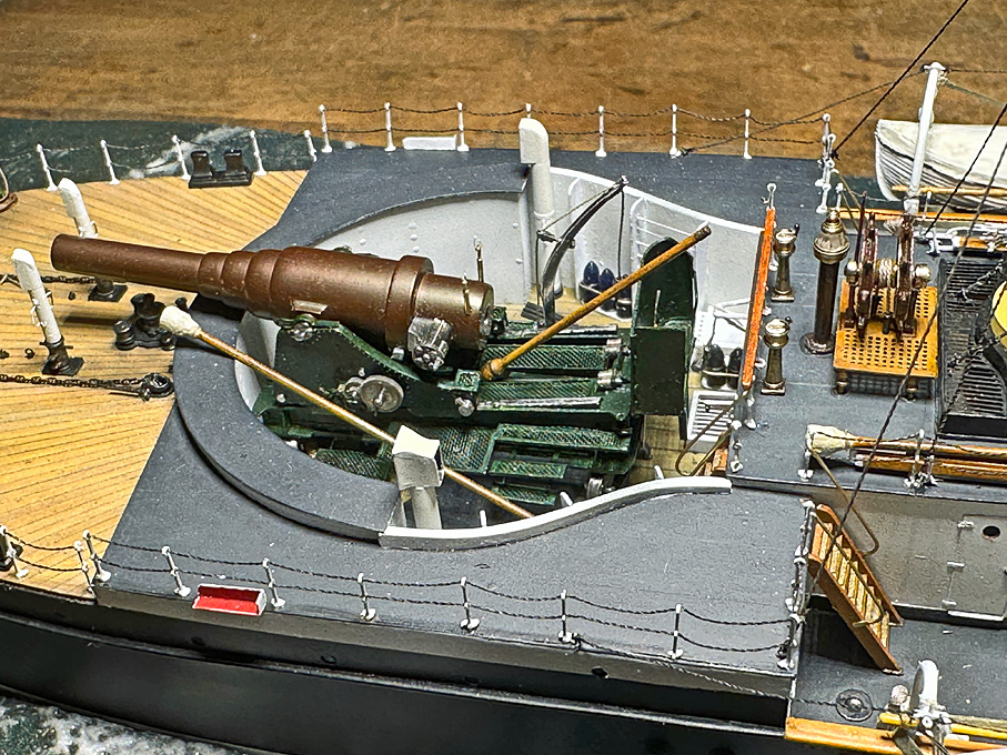
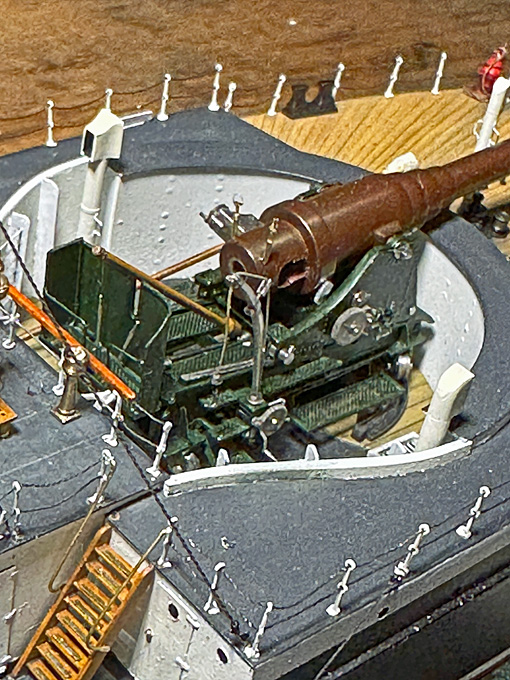
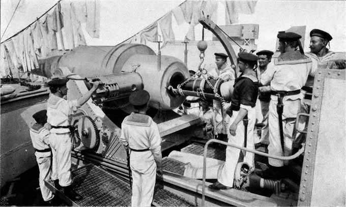
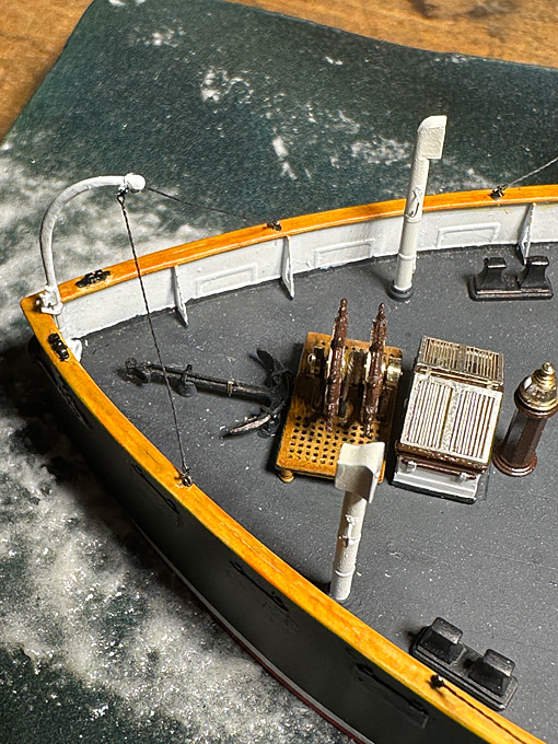
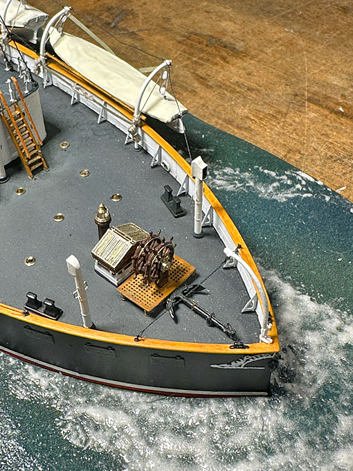
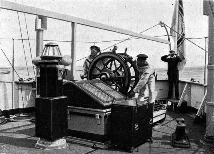
Just a little bit of further progress before the Easter-weekend … Stern anchor-crane There are drawings as well as the photograph below that show the anchor-crane in some detail. Basically, the dimensions are the same as that of the boat-davits, so that I was able to use a spare one that was left over. The ball at the end was drilled for the ring into which during service the anchor-tackle would be hooked. When not in service, the davit was steadied with two chain-stays. The set-up is very similar to that of the boat davits and the same processes were used. Gun-sights Gun-aiming technology didn’t significantly progress until towards the end of the 19th century. Just very basic front sights were used that sat on the trunnions, while the rear sights were adjustable in height for different distances and laterally for lead-angles. The rear sights used on the 30,5 cm gun a clearly visible on photograph below. Galster (1885) gives a detailed description. Basically, it is brass-tube of about 4 cm diameter that is set into a whole drilled vertically through the rear of the gun. In this tube runs a graduated brass-rod for setting the elevation as a function of the type of projectile used and the size of the powder charge. Firing tables were provided with the gun. On top of the rod is a cross-piece that runs in a dovetail-slot and allows to pre-set the lead-angle. The lead-angle was calculated inter alia on the basis of the estimated relative speed of the target and its distance. There was the usual V-notch on the top of cross-piece. It took several tries to produce these tiny pieces. In the end their dimensions are slightly over-scale due to the limitations of machining brass. Starting from 0.8 mm brass-nails, which are slightly harder than the usual brass wire due to the forging process, a 1.5 mm length of 0.2 mm diameter was step-turned over short lengths successively. Then a 0.2 mm long length was turned down to 0.7 mm diameter and this ‘rod’ with a disc at the end parted off. Luckily, I have a 0.2 mm collet for the lathe, so that the part could be inverted and the parted-off end cleaned up. With a pair of cutting-tweezers the disc was clipped down to the size of the cross-piece. Burrs were removed with a fine file. This part fits into a 2 mm long section of 0.3 mm OD brass-tube (from Albion metals). When I made the gun-barrel in about 2008, I did not have really the technology to safely drill to any depths the 0.3 mm holes for the sights, I was glad to be able to mill the flats with a broken drill that I had ground flat at the end. With my micro-milling machine and the dividing head this would not be a real issue anymore. Unfortunately, I forgot to do that before painting the barrel. Therefore, the sights had to be simply cemented onto the flats with a tiny drop of shellac. Before doing that I also added the protective frames over the sights using some 0.007 mm diameter silver-wire. Also installed were the last two of the ventilators for the officers’ mess. What remains now is the flagstaff and the ensign. I have already found a suitable technique for the complex ensign of the Imperial German Navy, but have to still get the right red for it. And then on to the crew … To be continued ....
- 935 replies
-
- 16
-

-

-
Ship Ribbing with CAD?
wefalck replied to Sanjith_D's topic in CAD and 3D Modelling/Drafting Plans with Software
Well, it depends what you are doing with them on a ship model ... Actually, I think there are four different topics here: 1) how to convert a 2D-paper drawing into a CAD-drawing 2) how to loft such drawings into a self-consistent data-set that produces a fair hull, and 3) how to convert the resulting CAD-drawing into instructions for the laser-cutter that produce the expected results. 4) is the laser-cutter available suitable for the task in hand As Chuck suggested, it may save a lot of time, effort and money to verify point 4 first. If the available laser-cutter is not suitable, it may be simpler to work the traditional way. On the other hand, as the envisaged model is planned to be only a foot and a half long, one may get away with quite thin (ply)wood or even cardstock. The bulkheads are only needed to define the shape of the hull, if the spaces in between are filled with a softer wood, e.g. balsa. The bulkhead do not need to be structural parts. One has to adapt the building technique to the available tools, in this case the laser-cutter. Some people work from sets of copies of original builders' plans, but it may be worthwhile going through steps (1) and (2) in any case, as this allows you to verify the fairing of the hull before one cuts anything. Even going only through step (1) is useful: if it turns out that a bulkhead is wrong, one can easily correct it in the 2D-CAD and print it out again. -
Krupp 420mm Big Bertha by Haliburton - Takom - 1/35
wefalck replied to Haliburton's topic in Non-ship/categorised builds
Well, it seems that Gruson in Magdeburg specialised in 'Hartguß' for armour and armour-penetrating projectiles: https://de.wikipedia.org/wiki/Grusonwerk. I would need to bring myself up to speed as to the metallurgy of the various types of 'Hartguß' developed for armour and amunition by Krupp, Gruson and others. Both the metallurgy and the processing determine the their properties for different applications. My area of interest in general is before 1890, so I am not so familiar with the later materials. To my knowledge HSS-tools were the only ones available to turn/mill steel during WW1. Carbide (WiDia) tools were only invented in 1926. So pre-forming shells by drawing and drop-forging saved a lot of difficult machining and, as noted before, aligns the grain in the material favourably. I gather the classification of artillery into guns, howitzers and mortars became a bit fluffy in the course of WW1, as certain howitzers were given a maximum elevation more like that of mortars. They became effectively longer-range mortars. Or, one could say that mortars were made longer in order to give the projectiles a greater V0. -
Krupp 420mm Big Bertha by Haliburton - Takom - 1/35
wefalck replied to Haliburton's topic in Non-ship/categorised builds
I didn't actually say that the shells as such were cast. I was referring to a special steel-alloy developped from the 1870s or so on by Krupp, which in German was called 'Hartguß'. Say in the 1880s, the shells, to my knowledge, actually were cast into cockilles, where the quick cooling surface hardened them. Howitzers like the one we are talking about were designed to destroy bunkers and other hardened facilities, so the shells need to be hard and tough. Too soft and they will use much of their kinetic energy for deformation and the energy will be distributed over a too wide cross-section - too hard and they will fragment on impact, again dispersing the energy. At that time, turning hardened steel was difficult to machine, so they wouldn't turn and bore shells from solid bar-stock. Rather, a process of drawing and drop-forging was used to give most of the shape. Drawing and forging also arranges the structure within the steel, to make it tougher. The square billets from which the process started in the film were presumably cast. Not sure, whether continuous casting and hot cutting would have been available at that time. At 16'10" in the film one can see that even late in the war (I gather the film is 1917/18ish) the shells were painted and were given painted/stencilled marks as to their type. Otherwise they may rust quickly, even if greased for the transport to the front. Firing a rusty shell would not be good for the gun and may difficult to load. Interestingly, our peace-time stocks and production capacities are just not capable of keeping up with war-time demands, as the war in Ukraine shows again. These large artillery barrels had only a limited life-time, after a certain number of shots they would be worn out. Peace-time shell supply presumably was calculated on this basis. -
Krupp 420mm Big Bertha by Haliburton - Takom - 1/35
wefalck replied to Haliburton's topic in Non-ship/categorised builds
@Jack12477, the young gentlemen seated to the right is wearing 'knickerbockers' or 'plus-fours' - this was the hip outdoor sports attire from the late 19th century to around the 1930s. They were used when cycling (no chain-guards, so that the trousers don't get caught), golfing (to prevent trousers getting dirty), hunting (same reason), etc. While not acceptable at formal occassion (unlike today), they were worn to show that you were a sporty person (very much like today people are wearing those horrible track-suits and the likes, even when they are not pursuing any sports). As to the colour and appearance of the projectiles: they would have been special 'hard-cast' steel, so when bare, a metallic grey. There would be also two or three guidance rings that are pressed into the rifling, probably copper or perhaps brass. The detonator (which in this case may be in the bottom of the shell) would be brass. I don't know what the WW1 practice at that time in Germany was, but normally shells would be colour-coded according to the type. I would assume that they were painted 'field-grey' or something like that to prevent rusting, perhaps with coloured bands or lettering to indicate the type. You would need to verify this against the literature. -
Ship Ribbing with CAD?
wefalck replied to Sanjith_D's topic in CAD and 3D Modelling/Drafting Plans with Software
I think this has been discussed before, watch out for key phrases, such as 'digitising plans'. In general you can import an image of the body plan into your CAD system and then retrace the frames. Once this is done, you have to complete each frame station with the contours of what you actually want to cut. I gather so are aiming for a so-called POB (plank-on-bulkhead) construction. So you need to draw the respective lines for cutting out. There is a lot more detail that has to go in than can be described in such a short post. You should look at the various contributions in this section here to get an idea. Once you have the basic hull representation in the CAD system, you have to turn this into the files needed for laser-cutting, i.e. arranging the pieces to be cut to fit the machine, efficiently use the wood etc. This file has to be saved in a format that is readable by the laser-cutting software. I gather there is also information on that in this section of the forum. Not sure that basswood is a good choice, I think plywood would be better. -
In general, when the bowsprit is next to the stem, rather than on top of it, you are likely looking at a running bowsprit. For obvious reasons, in this configuration there is no gammoning, but either an opening in the bulwark or an iron ring to hold the bowsprit down. Gammoning seems to be also associated mainly with galion-style bows. As one can see from the first two illustrations above, a closed bow would requires some akward arrangements for the gammoning as the stemhead is too narrow. When closed bows came into fashion around the middle of the 19th century the gammoning was replaced by wooden clamps or iron straps.
-
Looking good, the work! Somehow I thought that the exhaust pipe(s) from the safety-valves are connect to those steam-relief pipes that are attached to ships' smoke-stacks. Unlike for railway- or traction-engines and the like, you cannot just let the steam off into the the (usually enclosed) engine-room. Do you have drawings of the prototype arrangements?
- 128 replies
-
- 5
-
-
- zulu
- sternwheeler
- (and 1 more)
-
No update for the past three weeks - I hope everything is ok over there ... we seem to get rather mixed messages from that region.
-
I haven't build anything with decals since about 1980*, I think. Decal technology must have advanced considerably since then. If I understand the process correctly, then you can apply the 'softener' to already set decals in order to coerce them around obstacles? I am asking this question, because I just had the idea of laser-printing flags onto decal-sheet and then apply the decals on both sides to a piece of aluminium foil cut to the right size. With this softening and drying technique, the aluminium foil with the decals on could be 'draped' realistically. Does this sound feasible? *apart from the white boot-topping above the waterline that I put onto my current project, for which I used thin strips of white decal-sheet.
-
Thanks, gentlemen. I have not intention to leave this World in the next few months, so this is not going to be a 'project for life' 😉.
-
Thanks, in the meantime, when I did some searches on Fowler B6 it popped up there ... 100 € for a kit is quite a steep price actually (for me, as I am not used to buy kits, but only tools and books). How long is the model by the way ? I didn't look up the measures of the original.
-
OK, we are in serious thread-drift now ... the phenomenon we are discussing is called 'planned obsolescence'. It's something industry has been using for decades to keep up their sales. Perfectly useable hardware is made unserviceable by designing electronic components too flimsy so that they fail prematurely, well before the actual hardware is worn out. Or making software on purpose not backward compatible anymore, claiming that otherwise performance cannot be improved (even if objectively no improvement may be needed). The component concerned are often trivial, such as capacitors, but one has to replace the whole electronics and replacements are either not sold or made uneconomically expensive. In fact, the European Commission has been working for some years now on legislation to curb such practices, because they are wasteful of mineral resources and energy. I gather, as long as our economic philosophy is built on 'growth', it is difficult to combat such practices. Another dimension of the problem is, that industry faced with this 'threat' is switching to renting out 'services', rather than selling goods. To some degree this is also supported by environmentalists, as they claim that there is too much 'unused stock' in our society. Gone are the days (well into the 1990s) that Apple prided themselves that all their operating systems were backward compatible with existing software (their own). You could run ten-year old versions of wordprocessors on the latest version of the operating system. But even back in the 1990s already there were complaints that 'productivity' software had too many bells and whistles that very few people actually use in practice. Perhaps I am not such a sophisticated user, but there are very few functions that I constantly use in my wordprocessor, spreadsheet or drawing programs that were not available already 30 years ago ...
