wefalck
-
Posts
6,651 -
Joined
-
Last visited
Content Type
Profiles
Forums
Gallery
Events
Everything posted by wefalck
-
Another constraint towards the lower end is, that ropes of less than about 10 mm that move any kind of load are not normally used, as they become difficult to hold on to. Flag-lines and such, of course, would be much thinner and would have proportionately sizes pins, if not belayed on cleats.
-

SMS Karlsruhe by Wreck1919 - 1/100
wefalck replied to Wreck1919's topic in - Build logs for subjects built 1901 - Present Day
Nice progress! Looking at the chains, from which the boat is suspended, I think there should be a third one, leading to the stem- and stern-posts respectively. These chains are intended to limit the boat swinging forward and backward, when suspended from the davits. I think at that time the KM also used slip-hooks to attach the chains to the lower block of the davit, but this may be difficult to reproduce at this scale. The slip-hooks are there to ensure, that both tackles are releases at the same time, as otherwise the boat might be turned over in a sea. If you don't have it yet, you should perhaps get hold of a copy of BRIX, A. (1911-1929) Praktischer Schiffbau - Bootsbau (reprint 1982).- 394 p., Norderstedt/Hamburg (Egon Heinemann GmbH). The 4th to 7th editions would be more or less relevant to the period of SMS KARLSRUHE. Some of the editions are also available in digital form. -
Finish sequence
wefalck replied to shipman's topic in Painting, finishing and weathering products and techniques
A polyurethane formulation, I suppose, that is not brushed on, but wiped with a cloth, as was traditionally done for shellac. -
Finish sequence
wefalck replied to shipman's topic in Painting, finishing and weathering products and techniques
I haver never used tung oil, but understand that is an oxidising one (like lineseed oil). As the colleague said before, acrylics don’t like oily surfaces. So, there two options: either use oil-based paint, or use shellac or a sanding sealer instead of the tung oil. The latter two are compatible with acrylics. -
I believe barrels were branded with references. Otherwise, the stowage plan would tell where to find what.
-
If one can, one avoids exposing plank ends to the water, because this is where rot starts. So, the sternpost has a sort of rabbet into which the planking runs. The construction would be like that, that the sternpost has a notch cut out on which the transom rests. The planking runs across the transom, but as soon as it hits the sternpost, it runs into its rabbet instead.
- 312 replies
-
- 3
-

-
- Chile
- Latin America
- (and 6 more)
-
Pat, with my somewhat limited sailing experience I would say that two rounds usuallysufficient, particularly, when you finish of with half-hitch (not sure that this is the correct English term here ...). You may need space for a third-round for hanging the coiled rope. If the pin is too long, it take too long to belay.
-
Thresher & stable engine by RGL - FINISHED - Plus Model - 1/35
wefalck replied to RGL's topic in Non-ship/categorised builds
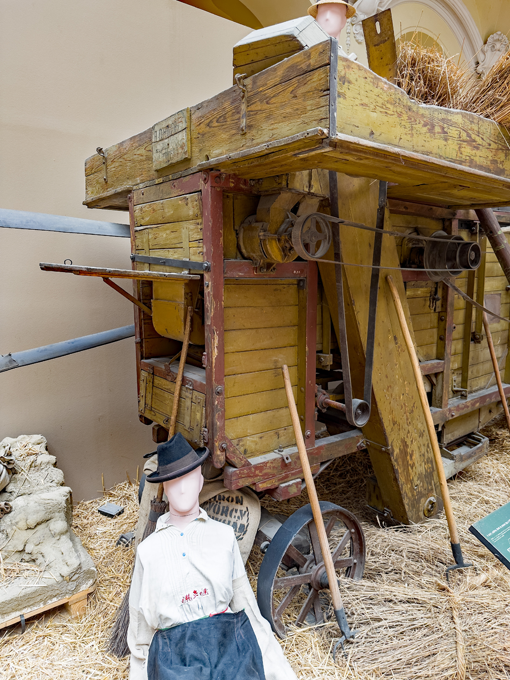
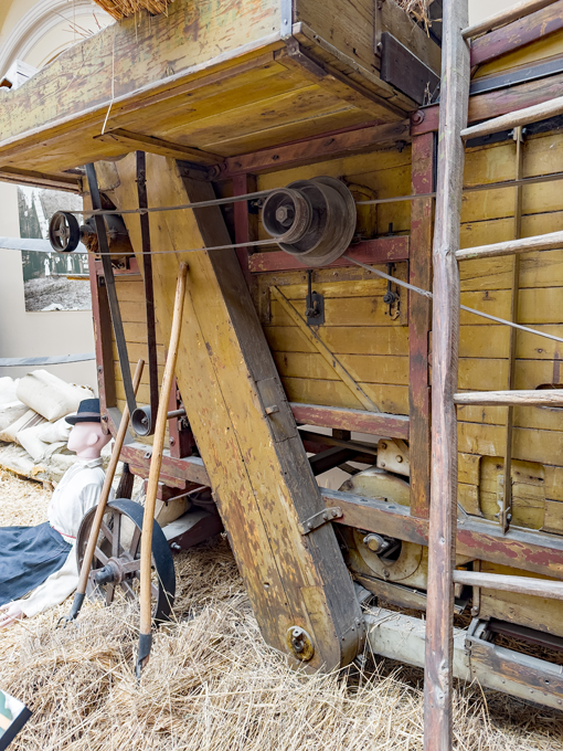
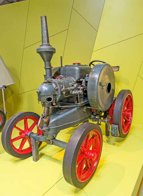
OK, here are the only two pictures of the thresher I took, plus a graphic that shows its functioning: I thought, I took more pictures, but perhaps not, because the little kit I have is one for a thresher of German make. Lanz, btw. made their own threshers to go with their portable steam-engines and later their Buldog. The pictures appear overexposed, because I lightened up the shadows so that one can better the mechanisms. The thresher is located in the Magyar Mezőgazdasági Múzeum (= Hungarian Agricultural Museum) in Budapest - https://www.mezogazdasagimuzeum.hu/exhibitions/the-history-of-hungarian-agriculture-from-the-beginning-to-1945. And now to the Lanz Ackerbulldog HL12 of 1924 in the Deutsche Museum in Munich. I forgot that this was the first model Lanz made and until 1938 the Bulldog considerably evolved. So the pictures would not be of much use to you. Here is just one to show you what they got: Here is a Web-page dedicated to the Bulldogs: http://www.lanz-bulldog-homepage.de/src/bida/hr8.html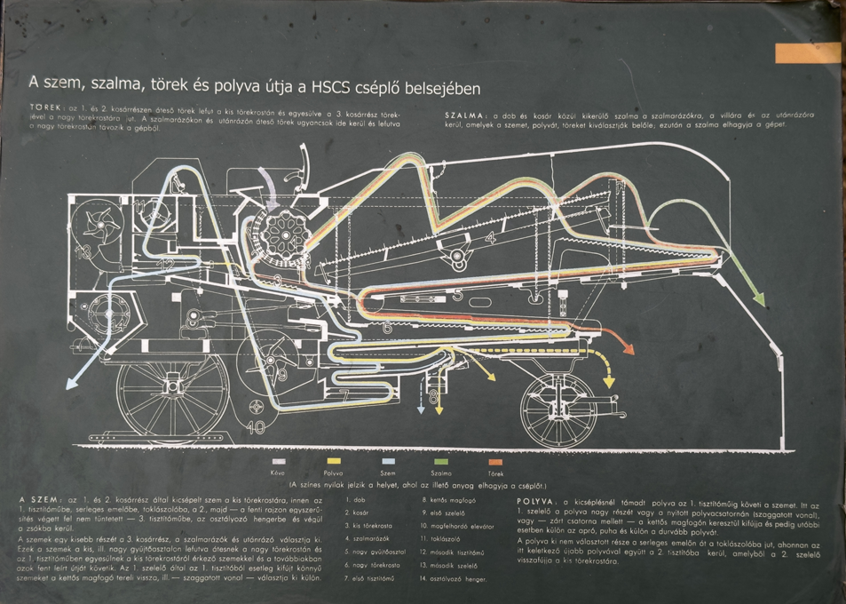
- 39 replies
-
- 11
-
-
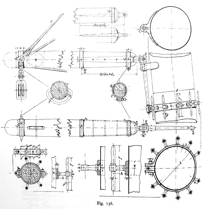
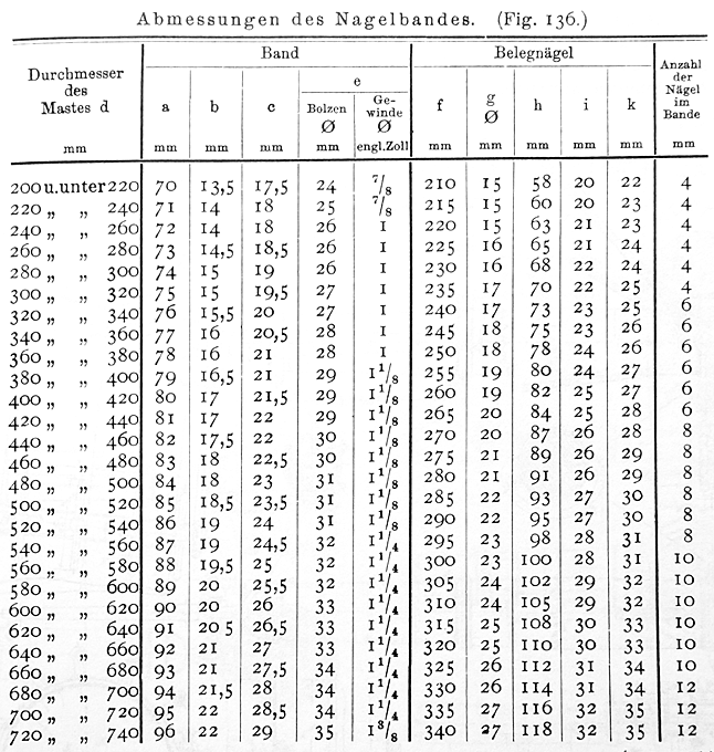
Apologies for the somewhat rough-and-ready images, but I was too lazy to pull out the scanner and just took a couple of shots with the telephone: From: MIDDENDORF, F.L. (1903): Bemastung und Takelung der Schiffe.- 401 p., Kassel (reprint 1977 by Horst Hamecher). These are for iron pins (= Belegnagel) in spiderbands (= Nagelband). Durchmesser stands for diameter. Unfortunately, the table only gives the total length f and the diameter of the lower part g, but not the other proportions. However, I think one can assume that the parts above and below the pinrail should stick out about the same length for functional reasons, which means that the total length below the handle should equal to the length of the handle plus the thickness of pinrail in which the pin is to be used. In any case, this discussion shows that the commercially/kit supplied belaying pins, particularly those made from wood, are just caricatures of belaying pins, being usually far to 'knobby'. From a manufacturing point of view this is quite understandable, as shape-turning such long, slender items is quite a challenge, even if one had a Swiss automatic lathe.
-
How will laser cutters compliment our hobby tomorrow?
wefalck replied to EspenT's topic in 3D-Printing and Laser-Cutting.
... I thought the thread was about home-use of such technologies. The traditional kit manufacturers sell the same models as 50 years ago, because the tooling as such and development of new tooling is expensive, too expensive for the the presumably declining margins due to Asian competition. The traditional tooling, such as moulds for injection moulding or casting metal parts, or the cutting templates for pre-cutting of wooden parts are rigid and expensive. These kit manufacturers probably should team up with Eastern European programmers and Asian workshops to stay in business. Otherwise, they will disappear. Small basement manufacturers seem to be much more flexible and adopted the new technologies fast, because the machinery is cheap compared to the traditional one and need very little skills in comparison to operate them. You can run a laser-cutter or 3D-printer without being a skilled mechanic. I don't think it is a question of plastic vs. wood, but a question of what look you want to achieve. For a 'realistic' model, it is not too difficult to achieve convincing wood-effects by painting (a technique in principle centuries old and known as 'wood-graining'), but the look of an 'artisanal' wood model can only be achieve only with wood. The fact that there are now many Russian, Ukrainian and Chinese wood-kits on the market seems to show that there still is a market, if the price is right. Some of these kits seem to be extremely well designed, so that also a relatively unexperienced modeller can achieve good results. This is likely to reduce the entrance threshold and may be good for this hobby. This is a bit off-topic, but the real problem for manufacturers of 'serious' models is, that over the past two decades or so children increasingly grow up in a cartoon and manga world. When most of us were children, these existed only magazines, but not everywhere around the childrens' rooms. They shape the childrens' world view and their expectations, when it comes to modelling. There seems to be quite a limited interest in history and historic or real world subjects, which is probably why the traditional manufacturers are struggling and selling mostly to past-middle-age adults. -
Thresher & stable engine by RGL - FINISHED - Plus Model - 1/35
wefalck replied to RGL's topic in Non-ship/categorised builds
You have there quite an international collection: an Austrian thresher (Hofherr & Schranz), a German bulb-engine agricultural tractor (Lanz Bulldog), and a Czech(?) hit-and-miss engine (Slavia). Originally, those threshers where either driven from a steam traction-engine or a portable steam-engine. There used to be some white-metal kits of traction-egines in 1/32 scale, but I am not sure that they are still available. In May this year I revisited the Agricultural Museum in Budapest after many decades and took a couple of pictures of the Hofherr & Schranz thresher in their collection. If you are interested, I can post the pictures here. For decades I had such a thresher kit in 1/87 scale in my drawer, but I haven't got around yet to scratch-build the matching portable-steam engine I wanted for a little diorama. I also remember the Lanz-Bulldog on the fields, when I was a little boy, but they became replaced by more modern diesel tractors in the 1960s. Many though survived and have been lovingly restored. Their engine sound is quite characterstic. There are quite a few pictures of them on the Internet. I also took a lot of shots of the one preserved in the Deutsche Museum in Munich, when I revisted the museum in July this year. However, it is probabaly a different model. Anyway, if you are interested, I can also post pictures here. -
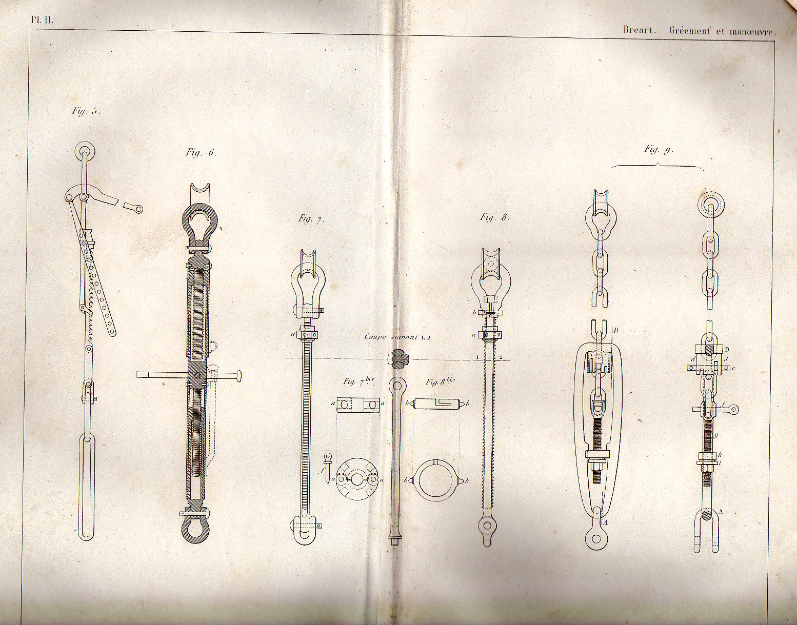
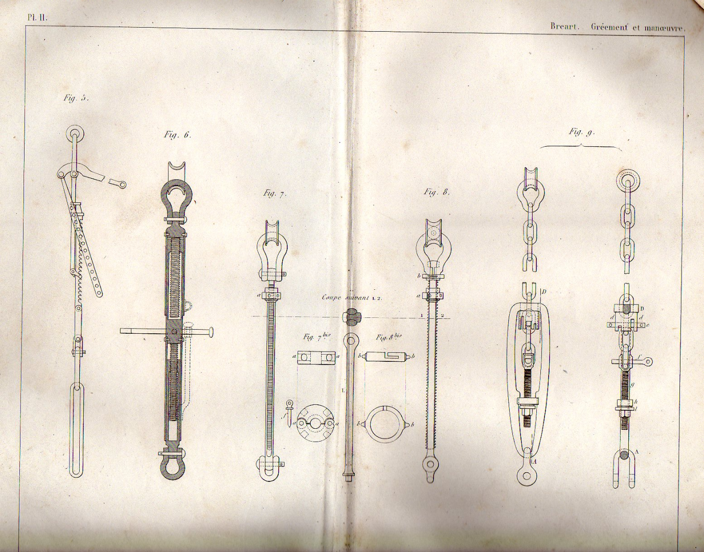
Found a picture, from BREART, E. (1885): Manuel du Gréement et de la Manœuvre des bâtiments à voile et à vapeur. Comprenant les matières exigées pour l’obtention du Brevet de Capitaine au long cours et de Maître au cabotage.- 459+13 p., 7 pl., Paris (Librairie Scientifique, industrielle et agricole, Eugène Lacroix). It's from a later period, but the left most illustration shows the principle that I remember having seen on the model in the Musée de la Marine (unfortunately lighting was not very conducive to taking pictures): The lever in Fig. 5, not fully drawn flips down parallel to the toothed rack and is tied against it. Such 'high-tech' solutions were not widespread in the navies, probably because battle damage would be more difficult to repair than the traditional system with deadeyes and lanyards. Before diving deeper into the rigging, you may want to get hold of some of the French literature on masting and rigging of the time, which can downloaded from the site of the French National Library: https://gallica.bnf.fr/, Unlike for the Google digitalisations, they unfold the tables in full! COSTE. F.-A. (18292): Manuel de Gréement ou l’art d’équiper les vaisseaux et autres batimens de mer, de tout ce qui est nécessaire a leurs mouvements.- 282 p., tables, Paris (Dezauche). Jaÿ, . (1860): Études sur le Greément d’après les réglement du 25 avril 1857, révisé en 1858.- Atlas du Génie Maritime, 2éme Serie, Annexe No. 1: 55 pl., Paris (Ministère de la Marine et des Colonies). VERDIER, M. (1837): Nouveau manuel complet de la marine. Premiere Partie. Gréement.- 290 p., Paris (Librairie Enciclopédique de Roret). Also, I would perouse @archjofo's building log here on LA CREOLE of 1827, which has wealth of information on French rigging in the second quarter of the 19th century.
- 62 replies
-
- 3
-
-
- belle poule
- OcCre
- (and 1 more)
-
In fact the 'Pretty Chicken' was quite a modern ship at the time and some advanced features were tried out on her. Instead of deadeyes or bottle-screws (which at that time did not really exist yet, due to the difficulty of producing consistent machine-screws before Maudsley invented the the lead-screw for lathes), some French ships used a sort of rack-and-lever system. If you have ever seen a device that was used in the old days to suspend a cauldron at adjustable heights over an open fire, that's the same system. I am still looking for a picture that illustrates this ... somewhere in my books I have a picture ... I suppose you could fashion this system from piercing saws with a fine pitch ...
- 62 replies
-
- 3
-
-
- belle poule
- OcCre
- (and 1 more)
-
How will laser cutters compliment our hobby tomorrow?
wefalck replied to EspenT's topic in 3D-Printing and Laser-Cutting.
Well, it's the old discussion of machine work vs. hand work ... there are people cutting their own files and saws and making their own drills to replicate ancient manufacturing process in e.g. watchmaking ... I got into laser-cutting with a simple and small machine for making intricate small parts, because it is less messy than photo-etching and because it can be used 'ad hoc', i.e. I can make parts, when I need them. Cutting larger pieces of wood requires a lot of supporting infrastructure, such as extraction fans or even water cooling, which makes their use difficult, unless you live in your own house. 3D-MLA-printing will be the future I think. However, it also requires considerable supporting infrastructure, as you need to have a workbench, where you can mess around with the resin, for cleaning the printer and the parts and for post-processing (UV-curing). So there are limitations depending on your personal circumstances. The question is, whether you want the best possible result, no matter what means, or whether you want to show off your craftmanship. -
I tend to mistrust zu Mondfeld somewhat, as he tried to cover too many periods ... I would also question the statement that only one size of pins was used on any one ship. I can understand the logic, but it also a question of space and materials economy. In addition, and perhaps most importantly, belaying a too thin rope on a too big pin either requires a lot of rounds or it will not be secure. It also take a long time to do. I have a table of belaying pin dimensions from Middendorf (1903), which I can copy here tomorrow. It would be correct for late 19th to early 20th century and contains metal pins for sure, but I am not certain about wooden pins.
-
I don't know, how big the model is, but is there so much sanding to do that you need an electric sander? There is also the risk that the edges of the sandpaper bite into concave sections of the hull. Sanding blocks and sanding foam-blocks might be a safer option.
-
I think, I would plank the transom after fitting it into place, although it would be easier to clamp down the planking when it is lying flat. On the topic of building-jig: yes, I suppose a jig would make the aligning of the bulkheads easier, as one can makr out their position on the board. I think a simple board would be sufficient on which you can clamp the backbone upside-down to facilitate planking. Boatbuilders strech a string from the bow to the transom and use a stick to measure symmetry of the frames or of the planking, when it is a clinker-build.
- 312 replies
-
- 2
-
-

-
- Chile
- Latin America
- (and 6 more)
-
Very nice model indeed and a subject not often, perhaps even for the first time, seen here ... If you happen to be in London, you may want to visit the London Canal Museum: https://www.arbeitskreis-historischer-schiffbau.de/mitglieder/ontour/london-canal-museum/. This page is in German, but you can have it easily translated these days. Outside the museum, which is an old ice-house, there is a harbour basin (Battlebridge Basin), in which during winter-time dozens of narrow-boats are laid up.
-
I couldn't check against my photographs, but the chain-plates look rather on the thin side to me.
-
... keep in mind that Javier (who is also here on MSW) mostly works in 1/150 to 1/200 scale and his creations are only a few centimeters long. I think I suggested earlier also to fill the spaces between the bulkheads, which makes fairing and planking easier.
- 312 replies
-
- 2
-
-
- Chile
- Latin America
- (and 6 more)
-
First of gratulations to this nice model and the gold medal! Concerning figures: 1/144 seems to be a common aircraft model scale. The German manufacturer Preiser (probably the best on the market for styrene figures) has a small range in that scale: https://www.preiserfiguren.de/download.php?file=PK 28 Seite 308.pdf. There are also numerous offers of 3D-printed military figures, but one would need to look around for another market platform after Shapeway went into bankruptcy last summer. I believe that the UK model railway N-scale is actually 1/148 rather than 1/160, so poking around British manufacturers might be helpful. In any case, the figures will need some carving and sculpting to bring them to the right era. This is not too difficult. I have just done this for my S.M.S. WESPE project here in 1/160 scale.
-
There are several options: - you can use your battens and mark off the position of bulkheads equally on both sides; one can do this with a piece of string, the length of which one adjusts iteratively together with the angle of the bulkhead until it is equal on both sides; always measure from the stem; this is perhaps the most precise method without tools. - you can draw/print the pattern of bulkheads on a piece of paper and, holding it over the framework, you adjust and glue in place the bulkheads one by one. - use something of which you are sure that it has a right angle and adjust the bulkheads against this. The boatbuilders of old probably would have used the first method ...
- 312 replies
-
- 5
-
-
-
- Chile
- Latin America
- (and 6 more)
-
I wouldn't know what is available in the USA. For me, at railway scales the manufacturer to go to is Preiser: https://www.preiserfiguren.de. Preiser has a small range of 1/100 figures, but basically only modern pedestrians for architectural models. There a dozens of manufacturers for military figures in styrene, casting resin, and white metal. I am not familiar with the current market in that respect. There are also numerous offers for 3D-printed figures on the respective platforms, mainly in the military and aircraft scales. Many of these figures seem to be of good animation and detailing, but the printing quality may vary. Sometimes they are scaleable and you can specify the scale you want. Another route are service providers of files for 3D-printing, which can be customised in sometimes quite sophisticated way, say with respect tot he animation and clothing. The problem is that they seem to mainly aim at the 'gaming' community, where there seems to be a fashion of gnome-like appearance. The latter is also a problem with many of the 1/72 scale figures that are available commercially (see https://www.plasticsoldierreview.com).
-
Yes, I would think that this would be a typical job for photoetching. I would actually give it to my laser-cutter to chew ... and then build up the body with acrylic gel, followed by some gilding. There are also these '3D-printing sticks', sort of hand-held extruders with which one can build-up such patterns.
-
However, if you cut the grating from a single sheet of wood, the grain will run into the wrong direction for one set of battens. One could improve on this by cutting the notches prototype fashion and then the matching battens from a sheet of wood with half the thickness only.