wefalck
-
Posts
6,664 -
Joined
-
Last visited
Content Type
Profiles
Forums
Gallery
Events
Everything posted by wefalck
-
The mill is actually a pirated copy of a development by the original UNIMAT people in Austria, first as a sort of toy with plastic parts and then all-metal: https://thecooltool.com/produkte/unimat-ml (sorry I didn't find an English Web-page).
-
As far as I can see, these Chines benchdrills have two ball-bearings, one up and one down. One would hope that they are of the kind also rated for axial pressure. So, in principle no problems with side loads. There shouldn't be a problem with using the benchdrill for light milling operations, as long as the quill is not run out. If you lock the quill in the up position with the thumb-screw provided, all the side thrust will be taken up by the bearings and no angular deflection occurs. One should note, that Jacobs drill-chucks are not designed for side loads. As I said earlier, you should look for the version with an ES collet chuck. These drill-chucks are not very precise anyway. ES collets nominally only go down to 0.5 mm minimum diameter. If you want to drill smaller holes, you need to look for drills with thicker shafts. There are the watchmakers HSS spiral drills with 1 mm that go down to 0.1 mm diameter. These would be my personal choice, but they are not so easy to find these days. Another option are the ubiquitous carbide drills with 3 mm or 1/8" shaft, but they are too delicate for my taste.
-
Perhaps then you should look at the drill-presses that these guys and others are making/selling: Go for the ES-collet version. There seem to be a lot of offers at various prices around the Internet. I think here on the forum somewhere there is also a review. I have had the predecessor of the current PROXXON bench-drill since the early 1980s and it still serves me well.

-

Good 'Hobby Quality' Metal Lathes
wefalck replied to tmj's topic in Modeling tools and Workshop Equipment
Well, drilling a 0.8 mm (my typical nail shaft diameter) through hole into a 20 mm thick piece of steel would be a bit of challenge in itself ... could do it on the lathe into a piece of round steel. I don't have an arbor-press, so I would need to do the pressing on a vice. I have experimented with all sorts of carbide tooling, but as I don't have a really good way to sharpen them, I tend to use it only for rough work. The onyl exception is the so-called Swiss Lathe tooling, brazed carbide bits with a shaft of 4 mm x 4 mm that are used on automatic turning machines. Otherwise, I have come back to purpose-ground HSS tool-bits. In fact, my most-used bit for miniature work is one that is ground like a grooving tool with a front cutting edge exactly 0.4 mm wide. It cuts left and right, so I can work on parts from both sides without changing the tool. I have two versions, one with 0° cutting angle for brass and one with about 5° for both steel, aluminium and acrylics. I know, this is not the most efficient tool geometry, but I am not in 'production'. Still have to finish the tool-grinder I started to build ... -
To me it actually looks like a reasonably well-engineered piece with a design based on stock-material and -parts. However, looking at the technical specs, I think a spindle speed of only 2000 rpm is a bit on the low side. I would rather like to have something in the order of 5000 or for wood even higher. Obviously, I don't know the thinking of manufacturer behind not providing a T-slotted table. However, in modern manufacturing such tables are typically replaced by 'tool-plates', i.e. slabs of steel or aluminium with patterns of threaded holes for various types of fasteners. Such plates are also useful for use with excentric low-profile clamping kits (such as the 'mitee-bites'). One could drill holes at suitable locations into the table, thread them and then clamp a toolmakers vice onto it. For larger parts, two-part vices are useful. I didn't compare the enveloppes, but I have the feeling the PROXXON MF70 might be a better choice as a mill, but it does not have the quill for drilling.
-
The question would be, whether they really went to the trouble of cooking on relatively short passages in the North Sea or around the Bay of Biscay etc. Given the rough seas that pervail usually in these areas, this would be a considerable fire risk. I am not an expert on this, but the archaeological evidence I seem to have seen points at clay or bronze pots with three little feet protruding from the bottom, that were set into(!) the fire/glowing embers in a hearth. There is archaeological evidence for brick hearths being used on slightly later cogs. This kind of arrangement is still in use in other areas around the world, for instance on dhows of the Indian Ocean.
-
Good 'Hobby Quality' Metal Lathes
wefalck replied to tmj's topic in Modeling tools and Workshop Equipment
In fact, for such tiny parts in brass, I use nails as stock. The stamping process noticeable hardende the brass. I know, many modellers are afraid of steel and some frown upon it because it may rust, but early on in my 'career' as self-taught turner, I discovered that I liked working with steel. It depends, of course, on what kind of steel you can find, some steels are very easy to turn and others are a real pain. -
Good 'Hobby Quality' Metal Lathes
wefalck replied to tmj's topic in Modeling tools and Workshop Equipment
I have made myself adjustable stops for the slides. Once you hit the desired diameter on a short length, you set the stop and then cut to the stop in subsequent steps. On my watchmakers lathe I can machine 0.3 mm diameter belaying pins from steel. Most brass I have access to is too soft for this. Shorter pieces I can machine down to 0.1 mm diameter and my collets go down to 0.2 mm. However, mass-fabrication of such parts is difficult and nerve-wrecking ... -
I gather, everyone has the tendency to go for domestic products (though the are often now in reality made somewhere in the Far East). I have a whole selection of Faber-Castell Pitt Artists Pens Brushes in different colours: https://www.faber-castell.com/products/PittArtistPenBrushIndiainkpenblack/167499. I wouldn't know about their availabilty in the 'Western Hemisphere'.
-
I have been using for this kind of 'calligraphy' acrylic artists' pens with a brush-like pen. These contain pigmented paints, not dyes that may look violett in thin layers. Due to the pigments they are also lightfast.
-
There are stories of Scandinavian wood-traders, usually worn-out trading vessels from other regions, that were literally floating on their loads ...
-
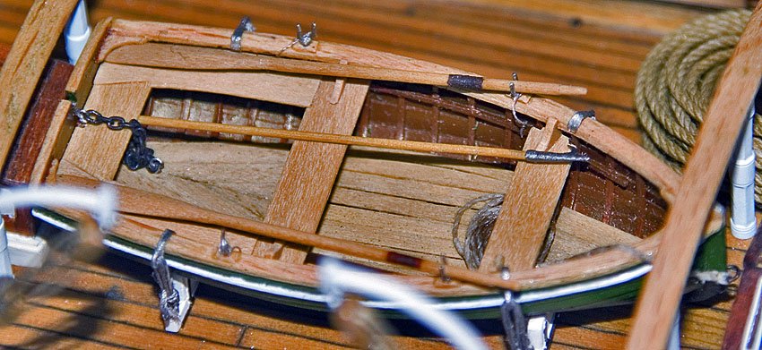
Having owned a rowing boat (or rather used my grandfather's) I was aware of the ergonomically correct position for rowing. I actually did not include the stretchers/foot-rests in my model, because it represented a working dinghy for the tug, in which they may get in the way of handling ropes etc. A decision at the expense of rowing efficiency. For a boat designed for moving from A to be B, I would include them. I think in such boats the thwarts would be fixed, as they are stiffening elements of the construction, which is why they are further strengthed with knees.
-
I don't remember and can't see very clearly what I did for the floorboards, but I think they were subdivided into four sections, a small triangula one at the bow, the two main ones along the boat, and another triangular one a the stern. They have be broken down into section that are quite easy to remove so that one can bail out the boat, even when out on the sea. I think, if you make paper templates for them and try out what works once the thwarts and stern-sheets are in place, that will give you guidance on how they should be constructed. One has to also think about placing the footrests for the rowers at the right place on the board. The analytical sections in 'Working Boats' give good guidance on that. Looking at my images, I have the feeling that I put the row-locks too close to the thwarts, though I think I took McKee's sketch of the anatomy of rowing as guidance.
-
Good 'Hobby Quality' Metal Lathes
wefalck replied to tmj's topic in Modeling tools and Workshop Equipment
Sorry, yes. There are also ES-type collets, but they are not very common. -
Good 'Hobby Quality' Metal Lathes
wefalck replied to tmj's topic in Modeling tools and Workshop Equipment
One should also keep in mind that these round belts running in a V-groove provide an important safety feature, when working with one's nose close to small workpieces: if something hooks, the belt acts as an overload-clutch by slipping. -
Good 'Hobby Quality' Metal Lathes
wefalck replied to tmj's topic in Modeling tools and Workshop Equipment
... but Sherline offers its very good chucks with 12 mm x 1 mm threads as well, I think. -
Good 'Hobby Quality' Metal Lathes
wefalck replied to tmj's topic in Modeling tools and Workshop Equipment
I don't remember what the spindle-thread is on the SL, I think 12 mm x 1 mm or 14 mm x 1 mm. You may be able to find ES-collet adapters with this thread. Or someone may be able to turn it up for you. A useful set of say ES16- collets can be had for little money these days. This so much safer for working on small parts, than working close to fast rotating jaws on a chuck ... You may also consider running the lathe off a momentary foot-switch. This keeps your hands free and in an emergency, you just lift your foot to stop the lathe, rather than having to reach for a switch. As the motor is an ordinary brushed one, you can use an electronic light-dimmer as speed-control. Over here in Europe with dimmers that plug into wall-sockets into which then your lathe can be plugged. They are cheap. You loose power, but for working on small-diameter parts that loss of torque doesn't really matter. I have used such configuration for many years. -
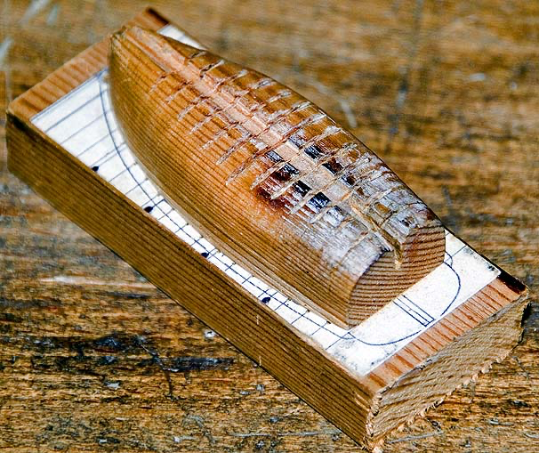
Looking forward to see, how your project develops! When I build the miniature, I developed a wooden former from the 'bulkheads' include in MdKee's card-model. Over this the 0.4 mm x 0.4 mm wooden frames were bent and then over it the stem-keel-sternpost part was fastened. The transom, of course, was also attached before planking. If I remember well, the planks as drawn by McKee fitted quite well over this structure. The little brochure on clinker planking was published as a sort of by-product, while McKee was working on his 'Working Boats'. The latter is a more functional and constructional analysis than a comprehensive catalogue of all the crafts around Britain.
-
@Harvey Golden thanks for the link to this Norvegian restoration project. That report discusses exactly the features I am currently poring about and need to make decisions for my current project! I think I new about the museum in Hardanger, but was not aware of that report.
-
That's really realistic weathering 👍🏻
-
Never had any experience with pre-mixed shellac, even if it was decades old. May be a questions of brand and that the respective manufacturer added things into it that were not stable. In principle, shellac can be re-dissolved in alcohol without problems. My guess is that there were too many and too thick layers of shellac and too short drying times. I would alway wait a day between applications. It needs to be completely hardened before you can sand it anyway. Without sanding or rubbing down with steelwool between coats you will not get a good finish. A good shellac finish is very thin. With a good sanding-sealer underneath, you should get away with two maximum three applications by cotton cloth (never use a brush!). And: never mix paint/varnish families, stick to one formulation only.
-
16th to 19th is a very wide time-frame and one would also need to distinguish between merchantment and naval ships, plus whether we are talking about permanent or moveable partitions. At least from the 18th century on panelled partitions (as in doors in houses) were very common for 'better' partitions.
-
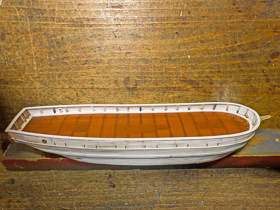
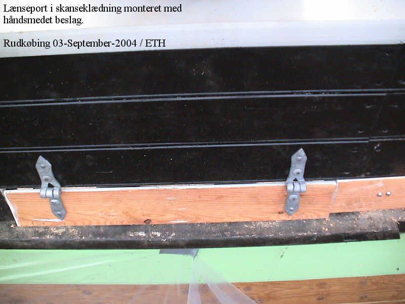
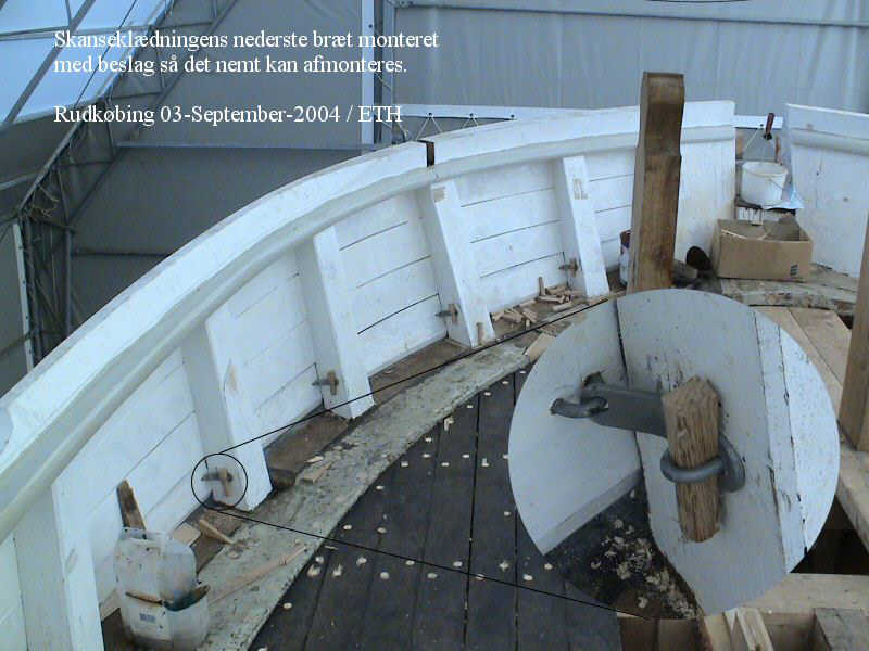
Thanks again for your moral support, verbal and via the buttons ! ****************************************************************** A Mystery Resolved When constructing the hull of the Rahschlup, it bugged me that there was no obvious way to free the deck quickly from larger amounts of water taken over in bad weather. The Jacht/Jagt-type vessels often have a gap between the covering board and lowest bulwark plank, but on all illustrations of Rahschlup-type vessels no such gap was visible. Freeing ports, as on modern ships came into use only later and the lead-lined gutters would not be sufficient. Then I scanned through the images of the restoration project (https://www.jensine.dk, but the link does not seem to work at the moment) for the Danish Jagt JENSINE (1852) for a different reason and two images caught my eye: They show that sections of the lowest bulwark plank are actually hinged and can swing out. In calm weather they are secured with latches. Subsequently, I noticed similar features on other restored vessels. I am not sure that this is an ideal solution for securing, as the wedges would need to be removed individually and kept for re-use. Also, the latch is attached to the plank section and could get caught between the plank and the covering board. I think a solution with a hook fastened to the stanchion that engages a staple in the plank would be a better solution. How to represent such parts now in 1/160? Producing the hinges will be relatively simple, although they will be tiny, but the hooks is another matter. For the hinges I took 2 mm long lengths of 0.1 mm tinned copper wire that was squeezed flat on my repurposed watchmaker jewelling tool to a predetermined thickness. These jewelling tools have a micro-meter stop that allows to very precisely set the distance between the anvil and the stamp. By squeezing, the ends of the flattened wire become rounded, which suited well the purpose. There was also a slight dimple in the anvil from the turning, which resulted in a slight boss in the middle of the strip to simulate the actual hinging mechanism. The ‘hinges’ were glued on with varnish. The latches are another matter and had to be much simplified. A double L-shape was bent into a short length of 0.1 mm tinned copper wire to simulate the hook and then one end was squeezed flat to represent the part that would have been screwed to the bulwark. These tiny pieces were then glued with varnish to the lowest bulwark planks and to the bulwark stanchion. I decided to make only every second space between the bulwarks ‘swinging out’ and scored the lowest plank on the outside lightly to mark these sections. Unfortunately, these parts are so tiny, that they are almost impossible to photograph, unless I use my macro-photography set-up and then they would probably look discouragingly crude … To be continued …
-
Thanks for your kind words. I am actually planning a miniature version in 1:160 scale for my current project.
-
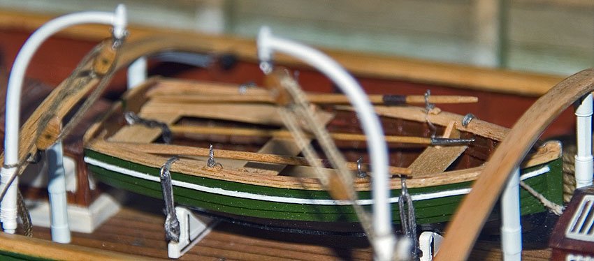
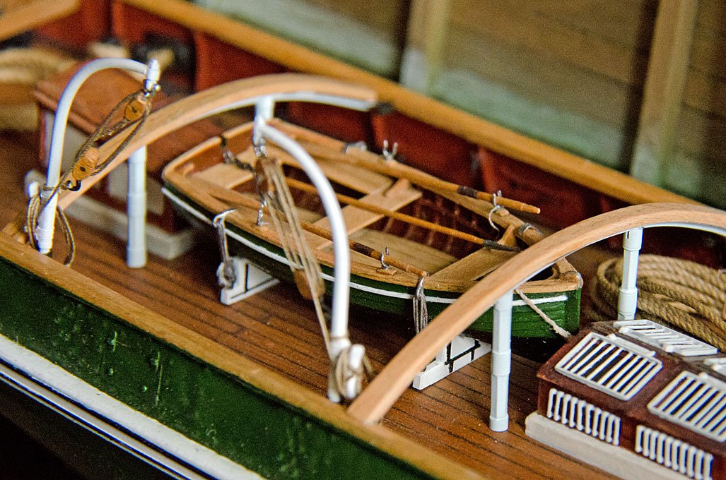
Had this booklet for many years, don’t remember when I bought it during my repeated visits to the NMM, when it was still intact. In the mid-1990s I used the half-model as a template for the dinghy for my late 1860s steam-tug project in 1:60 scale - mainly because the strakes were developed, which came very handy at this scale. The model was constructed over a wooden plug with bent wooden frames and strakes made from bakelite paper. Transom and all internal timbering again are wood. Unfortunately the 5 cm long model is a bit obscured by the tug‘s deck fittings.