wefalck
-
Posts
6,652 -
Joined
-
Last visited
Content Type
Profiles
Forums
Gallery
Events
Everything posted by wefalck
-
 In spite of your challenges, the planking looks good. As this is not an open boat, the inside look is not important and one can do a bit of tweaking. In clinker-planking it is important to remember that planks are not only tapered, but also curved (as seen in the plank diagram from the kit). That should take care of the up-sweep problem that you mentioned at some point.
 -
Would the smoke-stack a single tube or would it have sleeve? If it was a single tube, there would be a lot radiation towards the 'cool box' ... Somewhere towards the rear of the boat would seem more logical from a thermal point of view.
-
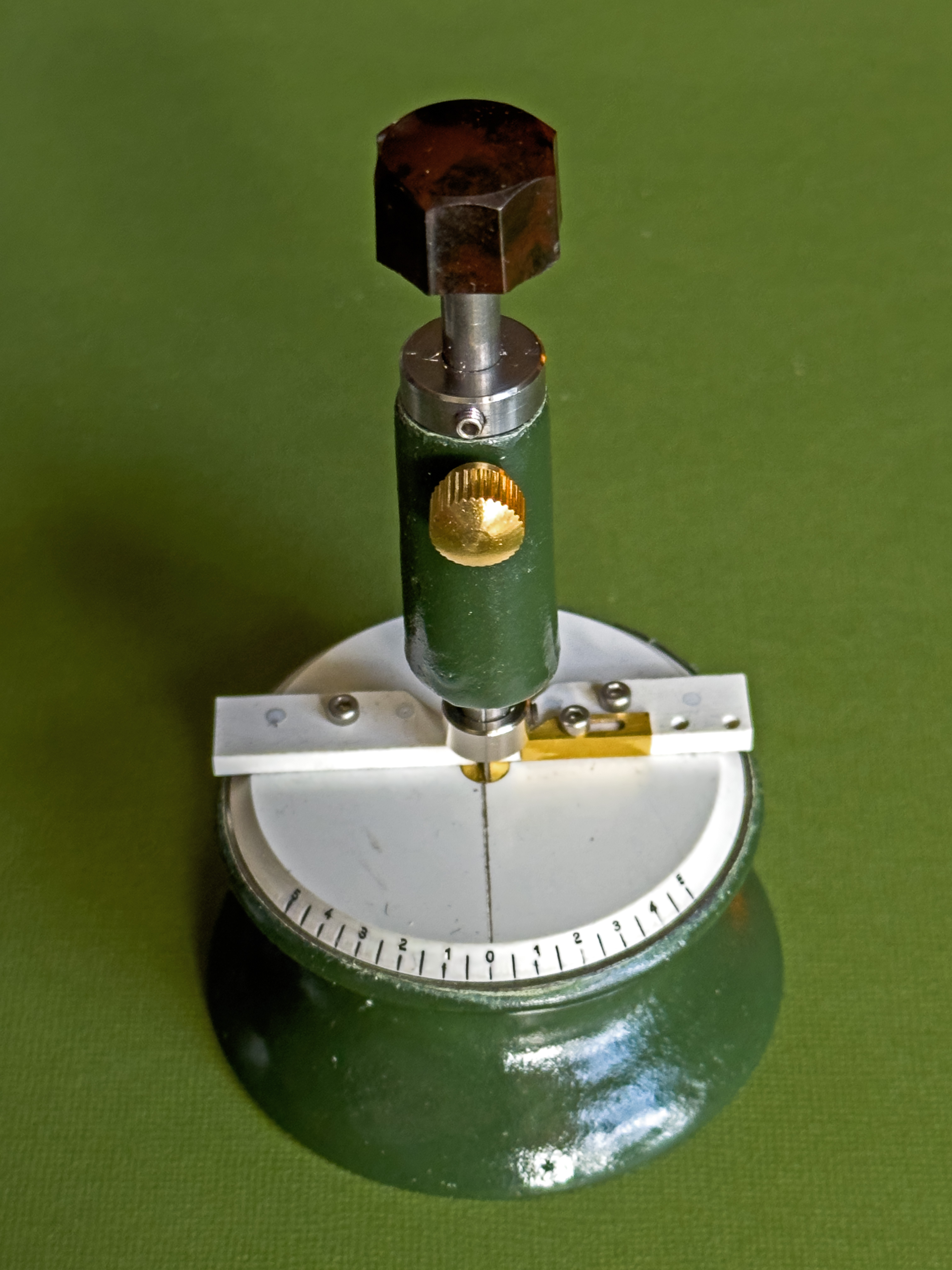
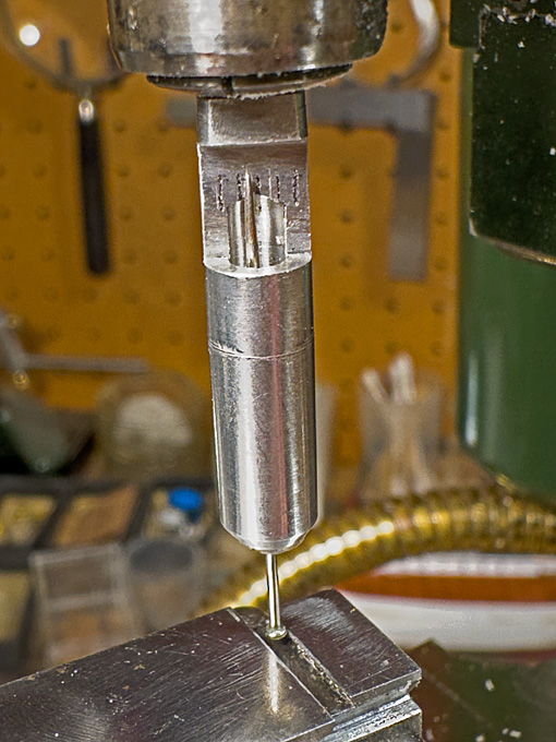
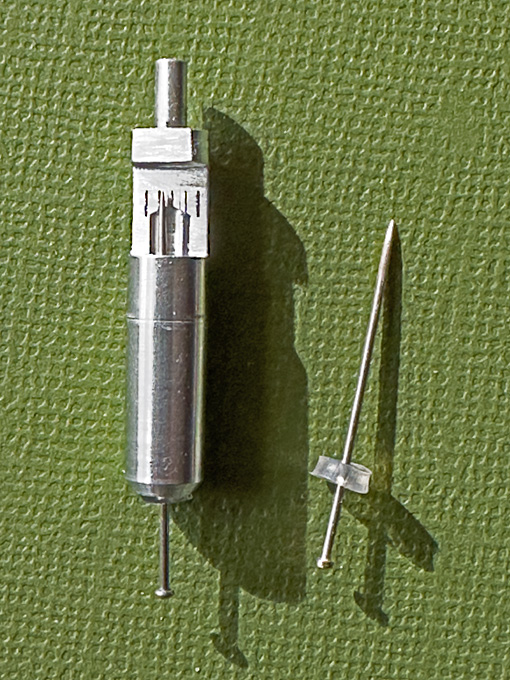
Pin-rails post-script When trying to fit the pin-rail with the consoles attached, I realised that I had overlooked a point: the tumble-home of the bulwark. This means that the angle between the pin-rails and the bulwark-stanchions is not 90°, but is a slightly obtuse angle of about 100°. In consequence, I had to remake the consoles with this angle. As the process is essentially the same as described in the previous post, I am only showing a picture of the final result. Pin-rail on consoles affixed temporarily Another small tool-making digression Milling the above profile required that the stock is oriented perfectly parallel to the X-axis of the micro-milling machine. While orienting the little vice is quite easy with the help of squares, orienting the stock on the face-plate would normally require tramming it in with a lever-gauge. The problem is that the lever gauges are far too big for the little milling machine. So far, I have eye-balled it with a pointed cutter in the spindle and some light test-cut to verify. This has been somewhat time-consuming and unsatisfactory. Thinking about the problem, I remembered the so-called ‘wiggler’ (https://www.instructables.com/Wiggler-Center-Finder-for-the-Lathe/) and designed a tool based on the same principle. It is basically a stick that is pivoted at some point along its length, so that it can move freely at an angle. There is longer and a shorter end. The latter is brought into touch with the workpiece and any movement is amplified by the longer end. I miniaturised this to a total length of 33 mm so that it fits easily between the milling spindle and the cross-slide. It consists of a piece of 6 mm diameter aluminium rod, that is turned down at one end to 2.4 mm to fit into a collet of that size. The diameter was chosen, because it is the shank diameter of the common burrs that I often use as milling cutters. That saves changing the collet after tramming. Mini-lever-gauge and its ‘mechanism’ (right) The rod is bored out 3 mm along most of its length and a 4 mm recess of 1.5 mm depth is turned in. This recess takes up a disc that has been punched out of a section of some polyethylene tubing. The feeler lever is an ordinary clothes pin, the head of which has been turned concentric (the stamping process of the pin production does not lead to completely concentric heads). At the upper end of the bore, a section of the aluminium rod is milled down to half the diameter, allowing to observe the movement the pin in this window. The polyethylene disc is secured in the recess with a drop of general-purpose glue and the pin pushed through it concentrically until the pointed end arrives at the milled-out section. The flat has a few lines engraved to be able to better judge the movement of the point. With this the little tool is complete In use the pin-head is brought into contact with the workpiece and the slide moved a tad in until the point coincides with one of the lines. When running up and down the workpiece edge, one observes the movement of the point and adjusts the angle of the workpiece until the point remains steady. Tramming the mini-vice with the aid of the lever-gauge The tool is perhaps a bit crude and not as sensitive as a commercial lever gauge, but it serves the purpose. To be continued …
-
Could this mystery object be just a water tank to supply hand-wash basins and perhaps a toilet ?
-
That look like a glorified pen-holder with an ordinary drawing pen ... I have a whole collection of them, including the penholder from my school-days (when in art-class we did a bit of kalligraphy and pen-and-ink drawing). I have tried to use it with acrylic paints (Vallejo model air), but found that they dry rather fast, making it necessary to clean the pen frequently.
-
Looks really grotty ... as intended 👍🏻 I play around with gloss acrylic varnish and gloss acrylic gel to get the impression of something being wet, but I think I mentioned this already. NB, I wasn't aware that in the anglo-saxon world, culm means the gangue or tailings from coal-sorting or -washing. For me as a geologist Culm is a particular type of rock-formation (containing little coal actually) of the Carboniferous.
- 457 replies
-
- 2
-

-

-
- sternwheeler
- Hard Coal Navy
- (and 1 more)
-
Great work, as usual! Did you show somewhere how you did the blocks for the boat-derrick?
-
Before I had a lathe, I turned parts exactly the same way …
- 482 replies
-
- 2
-
-
- minesweeper
- Cape
- (and 1 more)
-
This boat has, indeed, rather full ends. I went back to the first page of the log and looked at the side elevation and one thing one notes that the planks rise at the ends - which is their natural tendency with full shape, particular for planks that are below the turn of the bilge. Could you perhaps mark on stem and stern the position where individul planks should land? A slight rise would actually take out some of the sharp bends - which is difficult to visualise and explain. I didn't go again through your research, are there any photographs of beached boats of this type (assuming that they have survived into the age of photography).
- 139 replies
-
- 6
-
-
-
- ancre
- Bateau de Lanveoc
- (and 2 more)
-
I think in some building processes, such cant-frames were actually fitted after the planking is on. Much like it is done in clinker building. This allows for a natural run of the planks, without forcing them around the cant-frames. However, doing it on the prototype, where the run of the planks is determined by tradition and the builder's experience is different from trying reproduce an actual run on a model.
- 139 replies
-
- 5
-
-
- ancre
- Bateau de Lanveoc
- (and 2 more)
-
If that is according to prototype ...
-
Metallic paint questions....
wefalck replied to CPDDET's topic in Painting, finishing and weathering products and techniques
The tinier the pigment particles are, the closer you get to a 'metal' look. In the old days I used to stir gold bronze paint really well and then let it settle for a while, after which I only worked with the small particles still floating on the surface. I gather there is a similar effect with the marker pens, as in these the metallic pigment particles have to be really small in order to pass through the felt-tip. -
Brass stock in small sections....?
wefalck replied to Mark Pearse's topic in Metal Work, Soldering and Metal Fittings
See my response in your RANGER building log ... -
Wire for standing rigging became more prevalent from the 1860s or so on, initially iron and then steel. I am quoting from memory, but wire rigging has about half the diameter for the same strength as hemp rigging. I would suggest to consult some contempory literature on yacht rigging for the dimensioning of the rigging and how the wire was worked. A diameter of 3 mm for the standing rigging of such heavily canvassed boat seems a bit too thin for the time. I have the feeling that crimping wire for standing rigging would have come into use much later than the early 1900s, but I am not so familiar with yachting practice. On commercial shipping more traditional methods with bound loops around deadeyes or hearts would have been used. Such arrangement is also easier to repair and does not require heavy tools. If traditional set-up methods were used for rigging, these can be easily reproduced in 1/12 scale. I don't see the need for any soldering.
-
I don't know about Australia and your location, but I typically buy brass profiles from shops that supply architects and architectural model builders (they become fewer though due to the competition from 3D-modelling and rendering). Otherwise, I often go to (mainly Chinese) ebay sources. OK, I feel a bit guilty about that, but they often have very good offers and a wide range of stuff that is difficult to find in physical shops - and it is my money we are talking about after all 🫣
-
If the main bow-lines indeed lead so far forward, they would need to somehow clear below the fore-course and should also not foul the fore-sheets, though the latter would be loose, when the bow-lines are in use. I wonder, why they wouldn't be led analogous to the main-topsail bow-lines.
-
Such low-flying exercises are very restricted in densly populated Europe (which is one reason, why e.g. German pilots train in the USA). I have seen and heard a couple of times F104s screaming along the river Rhine almost at the altitude of the tops of the poplars that fringe the river. And during the time of the Balkan Wars in the 1990s I lived in the flight-path close to Berlin's Tegel Airport. Commercial planes were usually still a couple of hundred meters up at that point when approaching and pilots presumably were used to it. But once or twice one of the huge USAF transport planes landed and it's quite frightening to see it almost filling the frame of your apartment window and one hopes that the pilots get it right ... 😲
-
You are off to a good start 👍🏻 I think some people also use small notched blocks of wood to keep the planks in place and that they nail to the bulkheads temporarily (but you risk splitting them).
-
Nice metalwork ! These bending tools are useful, I made one mysel.
- 482 replies
-
- 2
-
-
- minesweeper
- Cape
- (and 1 more)
-
Pat, I used to suffer from 'tool envy' for many years, until I entered professional life and was able to acquire machine tools. And as we know, machines/tools allow one to make more machines/tools. It kind of developed into a secondary/subsidiary hobby then, together with the supporting process and market knowledge. I love in particular the look and feel of pre-1950s tools and machines, before everything became plasticky and boxy.
-
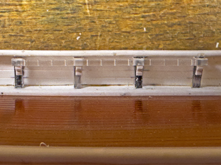
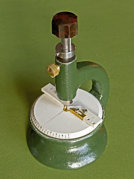
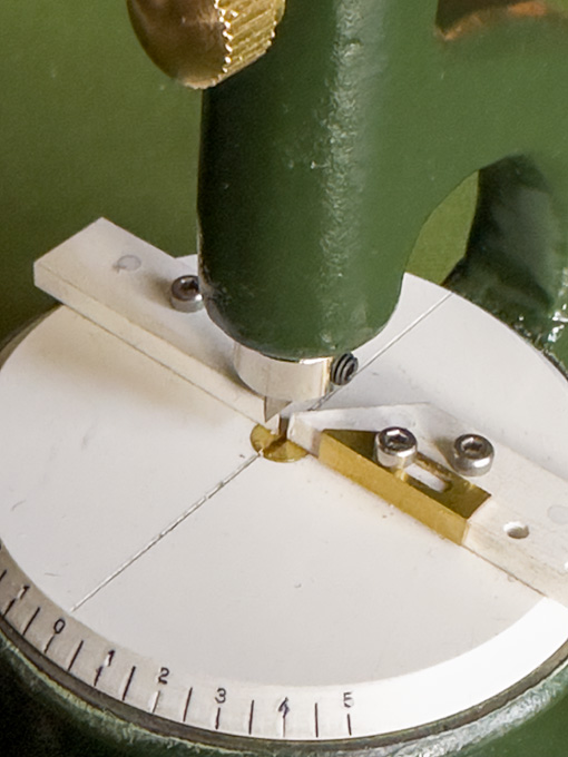
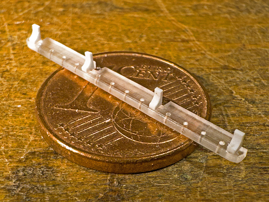
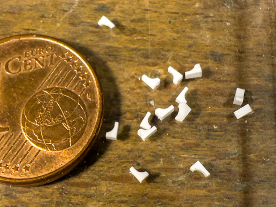
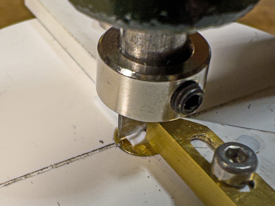
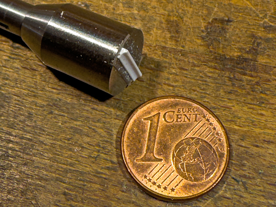
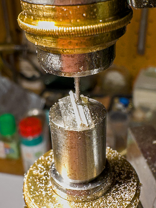
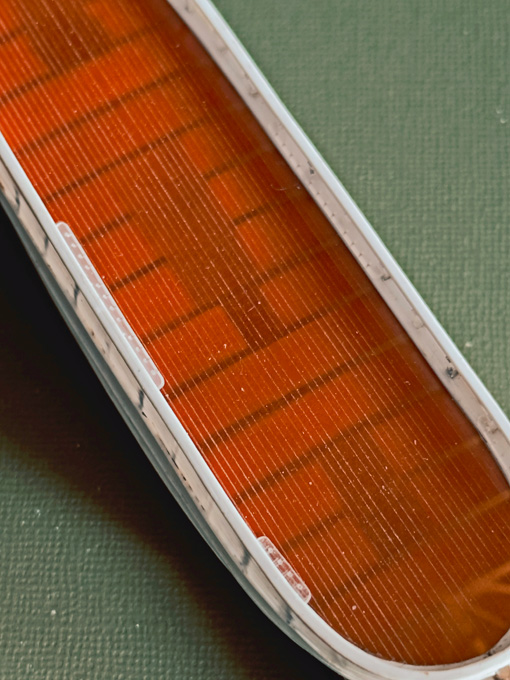
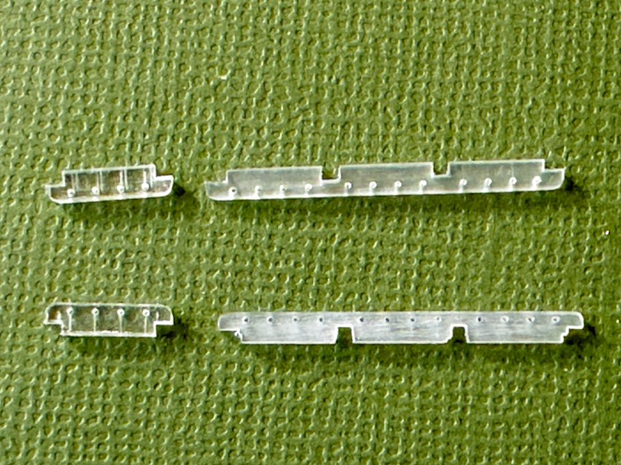
Thank you very much for the kind words and the many 'likes' 👍🏻 **************************************************************** Pin-rails 2 As can be seen on drawings and old photographs, the pin-rails often rested on consoles attached to the bulwark stanchions for added strength. As about a dozen were needed, they were ‘mass-produced’ from a shaped styrene profile. Milling the profile for the consoles to support the pin-rails The shaped profile for the consoles A 1.5 mm x 1 mm rod was stuck to a small ‘wax-chuck’ on the micro-milling machine with doubled-sided mounting tape. The rod was then oriented exactly parallel to the axis of the cross-slide and a hollow milled with a 1.5 mm ball-end burr. Slicing off consoles with the micro-guillotine The edges were rounded with a fine file. This profiled rod was then transferred to the newly built micro-guillotine and slices of 0.7 mm thickness cut off. These miniature consoles then were stuck to the underside of the pin-rails. Once painted, they will be attached as units to the bulwarks. Collection of consoles Consoles cemented to a pin-rail Micro-Guillotine The micro-guillotine was constructed around a part-machined cast-iron blank for a staking tool I found on ebay. Originally, I intended to fabricate all parts from steel, but I could not obtain a suitable blank for the rotating table and neither had the right steel bars in stock. So, for the time being at least, the parts were fabricated from 3 mm ABS sheet that I happened to have. The cutting blade is a shortened chisel-shaped scalpel-blade. It is set into an exactly fitting slot in the 6 mm steel runner and secured with a steel ring. The knob on the runner is an old bakelite instrument knob. The 6 mm wide blade restricts the cutting capacity to 3 mm for 90° cuts and correspondingly less for cuts at an angle. This is a conscient restriction, as this tool is really meant to only cut parts up to 2 mm by 2 mm cross-section. To cut at an angle, the plate is turned, rather than the cutter as in other designs. The narrow gap between the guides ensures that also very small parts can be cut. Their length can be set by the adjustable brass stop. To be continued …

-
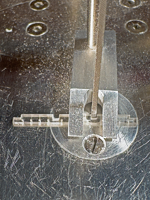
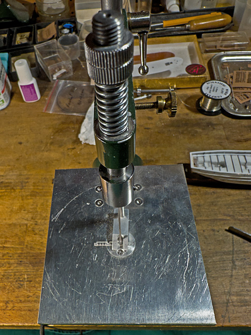
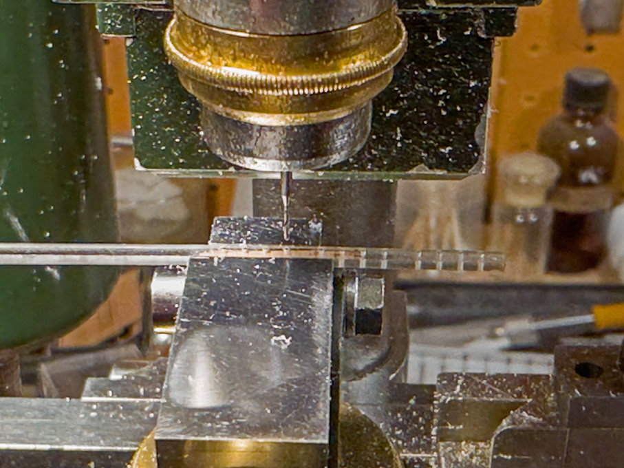
Work was been interrupted again, this time by some business travel to Tallinn for a few days, where I had also the opportunity to visit the Estonian Maritime Museum. Unfortunately, I came back from there with a sort of bronchitis that bogged me down for a couple of weeks ... Pin-rails Another delay in actual shop-work was caused that I first had to work out were the pin-rails would go and how many pins they have to have to provide the necessary belaying points. Drilling the pin-rails using the micro-mill as a coordinate drilling machine The pin-rails are 2.2 mm wide strips cut from 0.8 mm thick acrylic sheet. The holes were drilled using the micro-milling machine as a coordinate drill to get the distances right. The outer edges of the pin-rails were rounded as can be seen on many prototype photographs. The inner edges were notched for the bulwark stanchions on the filing-machine. Cutting the notches for the stanchions on the filing-machine Cutting the notches for the stanchions on the filing-machine Collection of pin-rails Pin-rails loosely attached at their designated location To be continued …
-
Tapering Masts and Arms the easy way
wefalck replied to Johnny Mike's topic in Masting, rigging and sails
That's a good idea for making tapered dowels and I seem to remember to have seen a similar procedure in the wide realm of YouTube, but not for model building. As others have already pointed out, masts and other spars are often not simply tapered and in addition have square or octogonal sections. Having observed that, I think the disc-sander method could be a good idea for quick material removal to arrive at the envelope of the more articulate shaped spars. After that, one would need to resort to another method to give them the exact shape.