


wefalck
-
Posts
6,652 -
Joined
-
Last visited
Content Type
Profiles
Forums
Gallery
Events
Everything posted by wefalck
-
 If you make the metal-work in brass, instead of painting, you could also look into self-tinning solution. Over here in Europe some model-shops carry it, but otherwise it can be found in electronics supply shops - nothing looks like metal - like metal
 -
Once you get used to the small scale, it is not so different from working at a larger scale. The problem are only the materials limits: you can get thin enough wires, (metal/plastic) sheets, threads etc. or at those small sizes they become difficult or impossible to work ... well of course, age takes a toll on our eyesight and perhaps dexterity too 😐
- 457 replies
-
- 6
-

-
- sternwheeler
- Hard Coal Navy
- (and 1 more)
-
I think one needs to also differentiate between the time before around 1850 and after and the regions. From the later 1830s or so on gasification of coal (gas for street and then domestic lighting and heating) and the production of coke for blast furnaces rapidly increased, initally in the UK and then on the continent. A byproduct from this process is coal-tar and -pitch, which is black, as opposed to the brownish colour of Stockholm tar. From that period on coal-tar was increasingly used on ships, making the standing rigging black or dark grey when weathering. For the running rigging Stockholm tar may have been used still for a longer time. The availability and price of coal-tar varied across the European regions. I would assume that Stockholm tar persisted longer e.g. in the Baltic area, as it was closer to the sources of Stockholm tar and more distant to the industrialised areas that produced the coal-tar. Thus I would expect a stronger contrast between standing and running rigging from the second half of the 19th century on.
-
Yep, cruises on the Seine can be nice, although a bit touristy. Done this a number of times, including taking our wedding party on a lunch-time trip and several dinner cruises with visiting relatives. I am ashamed to say, that we haven't visited Notre-Dame since it reopened - I hate queuing and remember those days, when you could just popp in. Did you visit the Musée de la Marine?
-
Off to a good start then! Well, boat covers often were painted(!) canvas, so in principle could be any colour. I gather some off-white, simulating originally white but slightly yellowed (due to the lineseed-oil as binder) paint could be a good option. I gather, sails in N-America were usually made from cotton, while in Europe more often flax was used, at least for the heavier qualities. Cotton does not yellow, so a somewhat dirty, i.e. very light grey would be good for the sails.
-
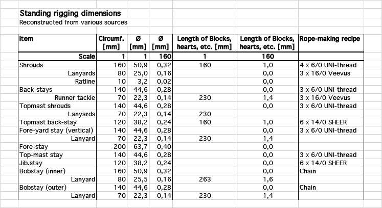
Johann, Costé has a number of tables at the end that give the proportions of different parts. However, they are mainly useful, I think, when you have to reconstruct a sail-plan from scratch. In my case, I had the original sail-plan and spar dimensions. In fact, much of the literature is concerned with the preferable proportions of the spars, which in my case is given in sufficient detail. For the dimensioning of the standing and running rigging I mainly worked from Biddlecombe, but compared his data with those from the other sources.
-
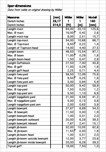
Thank you very much for the continued interest in this project 👍🏻 ********************************** Developing the Rigging Warrant It may seem strange to talk about the rigging warrant at this stage, but as much of the supporting fittings have to be reconstructed from sources and certain fittings, such as pin-rails or cleats, have to be put into place before painting, now is the time to develop at least an outline for it. Spar-dimensions as per table on original drawing by Möller The original drawings comprise a sail-plan and a spar-list with dimensions, which is a good start. However, as this is the builder’s and not a modeller’s plan, there are no details on the actual execution of the rig. These have to be reconstructed from sources from around the middle of the 19th century, notably BIDDLECOMBE, G. (1848): The Art of Rigging.- 155 p., Salem, Ma. (Reprint 1990 by Dover Publication, New York). BOBRIK, E. (1848): Handbuch der praktischen Seefahrtskunde, Schiffgebäudekunde, Zurüstungskunde, Manövrierkunde, Ankerkunde, Tafeln zur Schifferkunde.- 604 p. + plates, Leipzig (reprint 1978 by Horst Hamecher, Kassel). Costé, F.-A. (1829): Manuel de Gréement ou l’art d’équiper les vaisseaux et autres batimens de mer, de tout ce qui est nécessaire a leurs mouvements.- 282 p., tables, Paris (Dezauche). Jaÿ, . (1860): Études sur le Greément d’après les réglement du 25 avril 1857, révisé en 1858.- Atlas du Génie Maritime, 2éme Serie, Annexe No. 1: 55 pl., Paris (Ministère de la Marine et des Colonies). KIPPING, R. (1853): Rudimentary Treatise on Masting, Mast-Making, and Rigging of Ships.- 150 p., London (John Weale). MIDDENDORF, F.L. (1903): Bemastung und Takelung der Schiffe.- 401 p., Kassel (reprint 1977 by Horst Hamecher). – this is a bit late, but has useful tables with dimensions of parts While these works contain many useful tables and sometimes beautiful detailed drawings, I realised that they are of limited use for this project as they mainly deal with larger ships. Only occasionally they give information on rigging practice for single-masted vessels. In some cases information on the foremast and bowsprit/jibboom of topsail-schooner was useful, as their rigging layout is similar. The popular secondary literature on, e.g. British or French naval cutters, that have at a first glance a similar sail-plan, also is only of limited value, as they typically have a running bowsprit, and not a fixed one with jib-boom. So, much had to be interpolated, also from secondary sources covering earlier or later periods. I also studied numerous images of German, Danish, Swedish, and Norwegian sloops operating in the Baltic with respect to the arrangement of stays, shrouds, backstays, topmast-shrouds, -stays, -backstays, and the bowsprit/jibboom. A considerable variability in layouts was observed. Although the models of sloops and topsail-schooners in the Altona Museum (Hamburg) were built and rigged at the turn of the 19th to the 20th century, the model builders included older professional riggers, who presumably were aware of the earlier practices. These models give a good overview of the variability of rigging layouts and the supporting structures at the hull and on the deck. With this information it has been possible to develop a draft warrant for the standing and (part of) the running that will help to dimension and locate the necessary pin-rails, rigging cleats, bollards, etc. Reconstructed dimensions for the standing rigging Reconstructed dimensions for (part of) the running rigging To be continued …

-
Well, it seems that in fact carved decorations were removed from some/certain ships at least before going to sea, particularly very prestigious one. This would apply more to figures and such things, rather than to ornaments. On humble ships, such as the NONSUCH, the carved decorations were probably not gilded, but rather paint yellow/ochre.
-
Old Solid Round Stone Identification Assistance
wefalck replied to Ashland1's topic in Nautical/Naval History
There are various other options in addition to the ones mentioned already: - A stone from a so-called glacier-mill - a natural phenomenon whereby a rock swirls around a sort of meltwater syphon under a glacier, creating a funnel-shaped feature and eventually an almost perfect sphere. - An early canon-ball, but it doesn't seem to be shaped well enough for that - A well-used stone from a ball-mill - a rotating steel cylinder in which several stones like this are placed to crush something; as the material seems to be limestone from the look of it, it would not be too hard and could crush probably only organic material. In what part of the world was it found? -
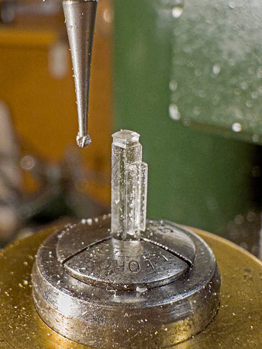
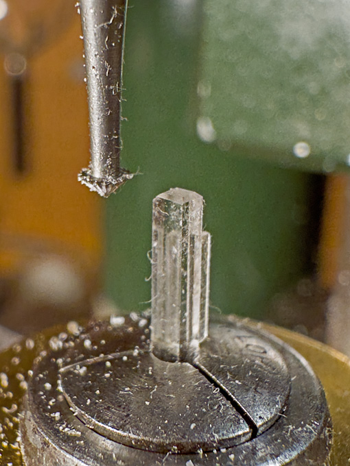
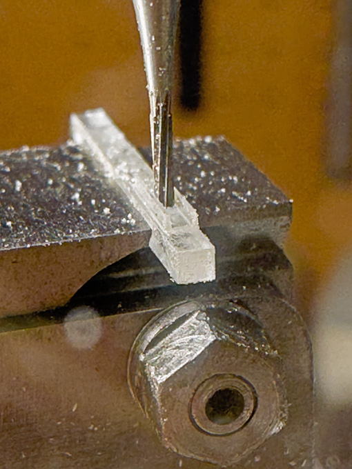
The shipyard had been closed for much of August, only the drawing office stayed open to prepare work for autumn ... ******************** Anchor-winch 4 The remaining item for the winch is the pawl-bit against which also the bowsprit rests. It is surprisingly thin, only 240 mm square, according to the original drawing, which conveniently translates to 1.5 mm on the model. A strip a tad wider than 2 mm was cut from a scrap of 1.5 mm thick acrylic glass. Care was taken to cut it parallel to a manufacturing edge, which is clean and square. In this way, only one edge needed to be machined and the manufactured edge provided a good datum for this. The pawl rest in a cast-iron U-shaped frame that is bolted to the front of the post (updating the design a bit from the older style wooden pawls drawn in the original drawing). Rather than adding this part to the post, I decided to mill it from the solid. Hence the 2 mm strip. Originally, I intended to drill 0.15 mm holes for the axes of the pawls, but my drills turned out to be too short for that. This would not be really necessary at this scale anyway, but would have later, once a wire was inserted, facilitated the positioning of the pawls. I have to eyeball it now. Milling the groove into the ‘cast-iron’ frame The post was milled to size, letting material for the frame for the pawls standing. The shape of the frame was then milled out and the ends rounded with a safe-edge file. In the final machining step, the groove was cut. Shaping the head of the pawl-bit I don’t have square collets (I plan to make one day a set of square insert collets for precisely holding square stock), so a round one had to make do for the next operation, namely shaping the head of the pawl-bit with different burrs. Because of the relatively soft acrylic glass and with light cuts, this is not a problem. Shaping the head of the pawl-bit The pawls will be short lengths of 0.2 mm x 1 mm styrene strips, but will be made only later, when everything comes together so as not to lose those tiny bits. To be continued …
-
I am using old cotton underwear and a cotton-wool ball inside. These are disposable, so no need to keep it.
-
I think it made perfect sense to cut notches for the cant-frames. Structural members need a positive location, it enhances the rigidity of the structure.
- 139 replies
-
- 4
-

-
-
- ancre
- Bateau de Lanveoc
- (and 2 more)
-
I wouldn't want to be inside one, when the gun was fired - that's awfully tight space. It seems that Peugot originally made a variety of articles using cast iron and steel, such as coffee-grinders, pepper mills and then started to make wheel-spokes, which took them into making bicycles and eventually cars etc. Bicycles and pepper mills are now independent companies from the car manufacturers.
-
Sound awfully familiar 😬 And yes, it's better to take pictures on a medium grey surface. I tend to use a medium green surface, as most of our parts are usually not green and that gives a good colour contrast. Good progress so far. Looking forward to the rest of the engine !
- 457 replies
-
- 3
-
-
-
- sternwheeler
- Hard Coal Navy
- (and 1 more)
-
On Royal Navy snows, how was the rope mast attached?
wefalck replied to Pitan's topic in Masting, rigging and sails
I cannot claim that I know what the RN did at the time, but I would think that there is an eyebolt going through a substantial member of the top. The lower end would be made fast again to an eyebolt that goes through the deck and a beam. It would be set tight with a lanyard and bull's eyes. A similar method was used for guiding the lower yards on schooners or cutters, where the gaff and mast-rings would interfer with parrels. Not sure that a brig with a rope instead of a secondary mast would actually be called a snow. The purpose of the so-called snow-mast is to allow the gaff and the parrel of the main-yard to be lowered without interfering with each other. -
There are no hard coal-mines in the UK anymore and neither in most European countries, only in Poland I think. This is becoming a real problem for the European steel-makers (Trump will be happy ...) and also for the preservation railways and traction-engine owners. Coal has become very expensive, as it is imported from South Africa and Australia.
- 457 replies
-
- 4
-
-
- sternwheeler
- Hard Coal Navy
- (and 1 more)
-
The small pad under the bit to slide under the deck is actually a clever idea 👍🏻
-
Iron Stropped Blocks - Kate Cory Whaling Brig
wefalck replied to Capt. Kelso's topic in Masting, rigging and sails
Are you referring to externally or internally iron-stropped blocks? The latter have been in use at least since the 17th century for specific heavy-duty applications, such as cat-tackles, but were not used much in the rigging as such - the external strop could cause damage to sails etc. Internally stropped blocks are much more complicated to manufacture for both, the prototype and the model. Hence, they were only used, when higher load-bearing capacity was required. They have to be attached to spars or rigging with either a hook or a ring that was forged as part of the strop. This restricts their use to certain locations. Hooks were used e.g. for blocks attached to masts or where they were constantly under load. Otherrwise their is a risk that they became unhooked, even when a musing was used. I gather blocks with rings only became more common when chain and wire-rope were introduced into the running rigging. They required shackles, which in turn only became more common once thread-cutting became standardised after the middle of the 19th century. With wire-rope only internally stropped blocks can be used, as it would not be possible to make safe strops from wire - the radii required are too tight around the block. From a mechanical perspective internally stropped blocks are a much better proposition than externally iron-stropped blocks, as the strop supports the axle just outside the sheave and is not separated from it by the wooden shell. The wooden shell is only there to prevent chaving and hooking in rigging and sails. Making internally stropped blocks in small sizes, say below 2 mm length has been bugging me for decades, as there is very little material for attaching a hook or eyebolt. -
It's a nice site and seems to have been considerably developed since I visited in 1994. The rea around is also pretty.
-
Well, water is not an organic solvent. I don’t know the composition of Minwax Poly and whether it would dissolve in Acetone. Rather think of nitro-based or good old nail varnish - not the modern acrylic variety.
-
Late 19th or Early 20th Century Running Rigging
wefalck replied to GrandpaPhil's topic in Masting, rigging and sails
In the early 20th steel was used for some parts of the running rigging that did not need to go around blocks. For those parts chain or hemp was used. -
I soak the lines in organic solvent-based quick-drying varnish. While the solvent evaporates, I coerce the line into the desired shape. A drop of acetone will reverse the process, if needed.
-
Nice ideas ! Looking at the engine, I actually wondered, whether the flywheel wouldn't actually run in a pit, making the engine foundations level with the engine-house floor. At leas this was the arrangement in most of such engines in preservation that I saw.
-
Fordson N roadless tractor by RGL - Plus Model - 1/35 - RESIN
wefalck replied to RGL's topic in Non-ship/categorised builds
Something that one doesn't see too often, neither as model nor preserved examples. I gather they were too complicated and expensive to maintain by the average farmer. Rubber or steel tyres (as in early ones) were easier on time and budget. In Germany, Lanz also made a tracke version of their Bulldog. Well done - what will you do with it? -
Somehow, I had missed this project up to now 🙁
