


wefalck
-
Posts
6,652 -
Joined
-
Last visited
Content Type
Profiles
Forums
Gallery
Events
Everything posted by wefalck
-
 That would be the subject of a book that I wanted to write for a long time (being a geochemist by training). You are absolutely right, that certain pigments were too expensive for rough shipboard use and others would not have been sufficiently lightfast. So, Boudriots list is a good starting point, as it mainly contains natural earth pigments that meet both requirements, beeing cheap and being stable. One would need to precise which decades of the 19th century we are talking about, as the pigment industry rapidly evolved in the course of the century. The evolving (industrial) chemistry led to the capability of synthesing certain pigments and thus becoming independent from the varying quality of natural mineral pigments. The increasing availability of by-products from coal-gasification from the 1840s on, lead also to the development of tar- and phenol-based artificial pigments towards the end of the 19th century. Interestingly, while the range and availability of pigments increased, from the 1860s on, ships became more sombre in livery, with black and white dominating, with the exception of spars and funnels that were ochre. Between the 1820 and the 1860s, ships were often quite colourful, with inside bulwarks, deckhouses, and the tips of spars painted in pastel ochre, green, or blue. With these pastel colours, a small amount of pigment could go a long way, when mixed with a white base pigment. BTW, the off- or dirty white mentioned in the literature is due to cheap and not very well refined lineseed oil and resins that yellows upon oxidation. This also makes coloured pigments dull. And from the mid-1860s on commercial antifouling paints in a variety of colours became available, not only in red ochre, but also in greens, blues, and browns.
 -
As one never knows which part would break, I would assume that at least one piece would be big enough to shape the main-topmast and the main-yard. Lower mast can not normally be replaced while at sea.
-
To this I would add 'patience'. Patience and to be content with stepwise progress (and sometimes set-backs) is the key to success - as you demonstrate all the time.
- 2,699 replies
-
- 7
-

-

-
- heller
- soleil royal
- (and 9 more)
-
Nice work, but weren't those bits not normally set on top of the deck-planking and the plates screwed down through it to some beams?
-
Made them only once and used heavy dark brown knitting yarn. This was twisted tightly and then soaked in shellac. Afterwards, it was roughend with coarse sandpaper. The tooping-lift then was fiddled through with a needle - as the yarn was two-strand, this was quite easy. In 1:60 scale it looked reasonably convincing. I actually bought some pipe-cleaners at the time (about 45 years ago), but dropped the idea, as running the topping-lift along the twisted wire didn't look good and it was impossible to dye the bright green fibres.
-
Thanks, gentlemen for your encouraging words ! Of course, acrylic glass was my go-to material. The first one came out ok, but then the second one snapped, and the third one jumped into some black workshop hole, when almost finished 🤬 ... I was too lazy to pull out the table saw and cut more acrylic glass strips, so I grabbed some suitable polystyrene strip and gave it a go. Acrylic glass machines and files/sands almost like metal, but small parts are rather brittle. When machining polystyrene, one has to be cautious to not overheat it, but it does not file very well and when sanding it leaves some 'fuzz' behind. Scraping with a scalpel takes care of that. However, being softer, it als more foregiving when handled. My concern is, that the softener in polystyrene will diffuse out over the decades and make it brittle. I also breaks down when exposed to UV-light, while acrylic glass largely remains unchanged over many decades. However, when painted, the risks are much lower.
-
Actually looks as if the dumb ferry is tied up to the sternwheeler? Over here in Europe there were various places with sidewheel-ferries, I seem to remember having seen one on the Fal River in Cornwall in around 1978 and very vaguely also on the Danube in the early 1970s.
- 457 replies
-
- 2
-
-
- sternwheeler
- Hard Coal Navy
- (and 1 more)
-
I think they put this light groove between the locating holes, because the locking pin would otherwise mar the rails in an uneven way, looking unsightly.
-
Pay attention, some of the pumps shown above are actually pumps for flushing the seats of ease, rather than pumping out the bilge. What material was used for the pumps depends on the availability of materials, technology and last not least the economic circumstances. Another factor to consider is the repairability by the owner and crew. Cast-iron became more widespread only from the middle of the 19th century on. Therefore, I would assume that in the USA log pumps would have been very common way beyond the middle of that century. At least in Europe they were.
-
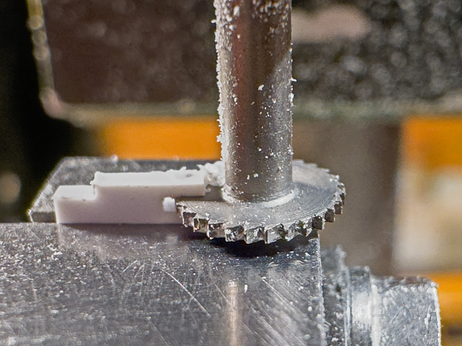
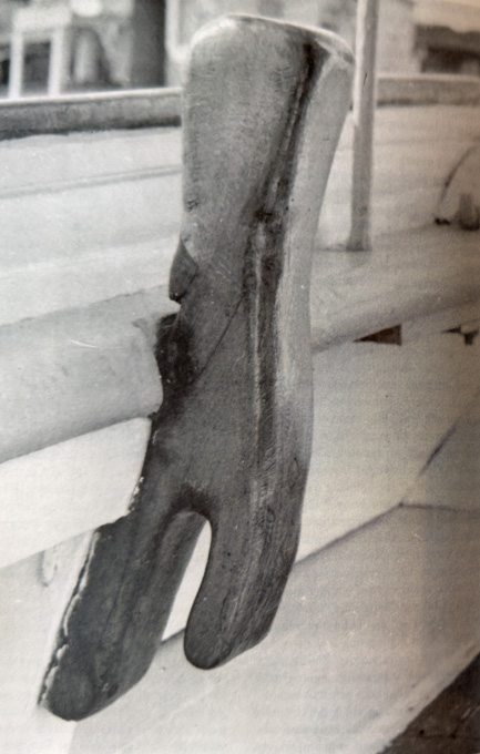
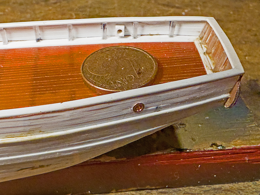
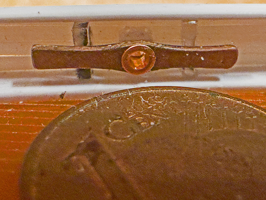
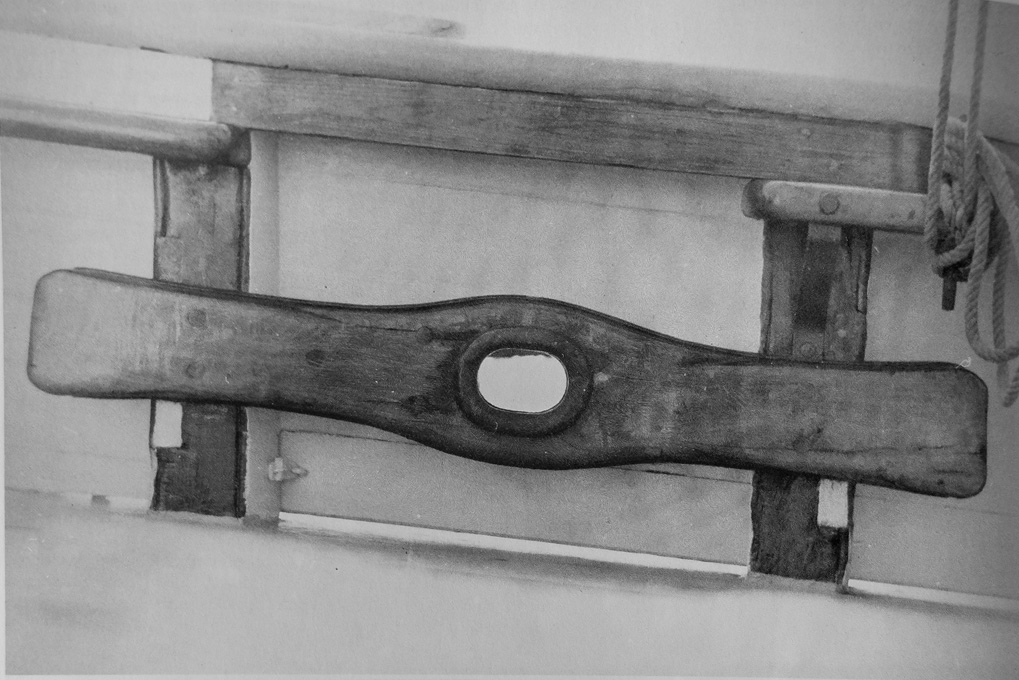
Cleats and Bollards In addition to belaying pins, also various types of cleats are distributed around the ship. Their type and location had to be reconstructed from various sources, such as models and early photographs. On paintings of such vessels, they are generally not visible. The first type concerns very large cleats that stretch across two bulwark stanchions. They are used for belaying heavy ropes, such as the main sheet. If they have a fairlead in middle, they also serve as mooring cleats. Mooring cleat (old photograph from unidentified book) The photograph was imported into my 2D CAD program (EazyDraw) and the outline traced and scaled to size. This served as the basis for the laser-cutting file. Material for two cleats was cut. The cleats are laminated from four layers of Canson-paper (if I had a more powerful laser, of course, they could have been cut from some 0.6 mm thick material in one go). The resulting part was finally filed to shape. The fairlead is a copper rivet. The completed mooring cleats I am not sure, whether the pipe of the fairlead is in some way supported in the space between the cleat and the bulwark planking. I have not been able to find any photographs that show this detail. However, for practical reason I inserted a square piece of polystyrene with an appropriate hole drilled through. This allows me to insert a shortened hollow rivet from each side and hide the seam conveniently. As the cleats will be represented in varnished wood, as can be seen on the above photograph and various models, it allows me to locate the cleats after all the painting is done. Fairleads from the outside Looking at the close-up photographs, I think the fairleads should have been turned a bit smaller on the outside diameter, but I am going to leave them like this. I also realised that my planking looks pretty awful and needs to be worked over … There are also several heavy cleats needed to belay for instance the backstays or the ropes used to secure the anchors. They are of a type that seems to have fallen out of modern use, namely half-cleats combined with a bollard Combination of bollard and half-cleat (old photograph from unidentified book) The shape was developed in the 2D CAD program and measurements for the machining derived from this. The rough shape was milled out of some 1 mm x 3 mm polystyrene profile. In fact the enveloppe is only 1 x 1.5 mm, but the additional material is needed initially to be able to hold the part in the vice. Milling the rough shape of the bollard/half-cleat combination Milling the rough shape of the bollard/half-cleat combination – close-up The final shape was given with the aid of various metal- and diamond-files and scraping to remove the fuzz from filing. I am using for this a ‘French’ type of pin-vise, on which I replaced the brass jaws with ones made from wood. One should note that, as they will attach to bulwark stanchions, their back has to be slightly curved. Filing a cleat to shape Roughed-out cleat (top) and finished cleat (bottom) To be continued …
-
Coming along nicely! In the past I used cored solder to represent such cringles. The bore was widened to a flare with a punch. The colour is close to zinc-plated hardware.
-
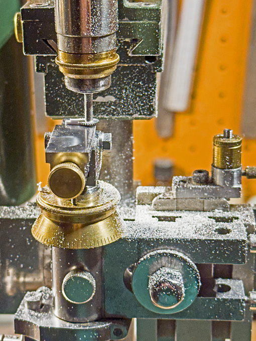
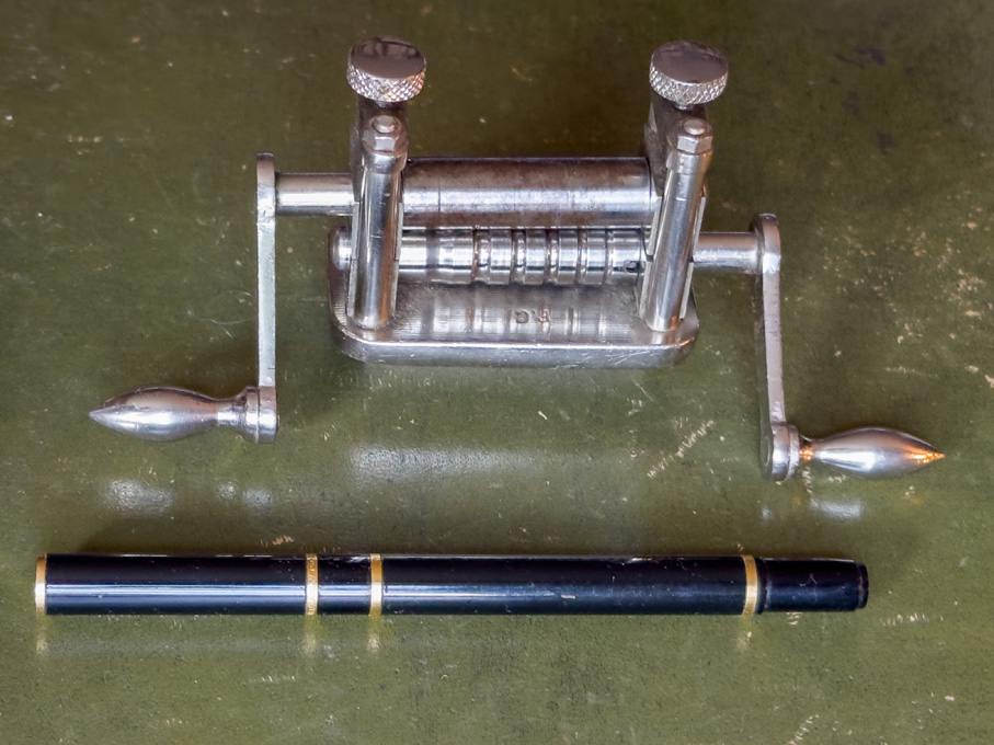
Finally got around to take a picture of the little rolling mill. As I said, it design purpose is to enlarge wedding-bands and the likes. For this different shaped grooves are cut into the rollers and there are several rollers with different groove geometries. As in this application the rollers would run at different speeds, two cranks are foreseen, allowing the move the ring forward and backward. However, I plan to fit a couple of meshing gears, allowing the run the rollers synchronous from one crank as would be needed for rolling wire. This also frees one hand to feed the wire in.
-
It seems that the Staedtler MARS QuickBow set does not have the straight handle, there is no slot for it. I have various sets, from my father/mother and perhaps older ones, plus my own, which is from 1966 - they all have this straight handle.
-
San Francisco cable car by kgstakes - FINISHED - OcCre
wefalck replied to kgstakes's topic in Non-ship/categorised builds
Perhaps the real ones have a plastic sleeve over them - paint would wear off quickly. Personally, I think brass looks nicer, but that then would be a deviation from the original - unless you can find old colour photographs from a time when they devoted the effort to polish the brass perhaps ... -
For engraving in metal there are two methods: - filling in with (black) paint; this should be a hard paint, so acrylics are not a good choice, as once the paint is dry, you would rub down the excess with fine(st) emery paper; this is a common process for instrument scales, door-signs, etc. - applying metal black (on suitable metals) and then same process as above. In principle the same technique can be applied to wood too. However, the wood needs to be sealed first with wood-sealer and then some gloss(!) varnish, so that excess paint can be wiped off quickly. Finally, the varnish can be rubbed down again or some matt varnish applied on top. Again this technique can also be applied to (laser-)engraved surface that have been painted. One would not rub down the varnish, however, but rather apply a thin coat of matt varnish. I have used all of the above techniques on a variety of materials.
-
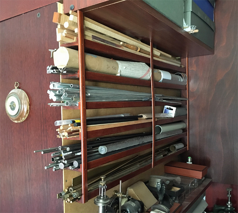
Can't you make such boxes yourself? You could fashion them as open trays right away. I don't know in what sizes cardboard is sold in the USA, but if there are sufficient lengths, one can cut strips of the desired width and assemble them with old-fashioned packaging tape (the one that needs to be wetted, not the self-adhesive one, which looses its tackiness over the years) or perhaps duct-tape. I for myself made a wall-hanging rack with horizontal shelves, so that short pieces can be kept at the front. Not an ideal solution, but the wall above my machines was the only place I had and here in Europe all materials are sold in 1 m lengths.
-
I think we had discussions on drafting implements in another thread quite a while ago. There is also an intermediate option, but I am not sure of the correct technical term in English. The translation from German would be something like 'funnel pen', which is quite descriptive. It is essentially a thin tube (the outside diameter determines the line width) with a funnel-shaped reservoir on top. A thin wire in the tube allows to declog it, when needed. It's the low-tech predecessor of the 'modern' drafting pen. They are designed for use with inks, rather than paints. However, I know from my mother that they are also used with gold suspensions in porcelain decoration. A while ago we discussed druxey's technique of making sails and I understood that drawing those lines with a bowpen also aims to add volume to the line to simulate the doubling of the seams. How much volume do those road-lining pens add ?
-
Perhaps your knight is a 'dragon whisperer' ? Many years ago I built a model of a Knight Templar with the same kind of helmet. One thing I was never too happy with it the metallic appearance of the material. Somehow, the surface of these castings is always a bit uneven. I never tackled another model like this, but perhaps today I would look into smoothing the surface with a burnishing steel or agate, rather than just polishing it with a felt-wheel. Has anyone tried to burnish such metal parts ?
-
Indeed, finding the right sequence of placing things on the model can cause a bit of headscratching, demanding foresight exercises, and imagining of possible interferences ... I tend to make the parts separately first and then paint and assemble everything. Nice work so far, as others already said!
- 482 replies
-
- 2
-
-
- minesweeper
- Cape
- (and 1 more)
-
Have to take some pictures ... it is actually a small rolling mill from the jewellery trade to enlarge rings. It needs to be modified still to drive both rollers for the purpose of rolling wire.
-
Valeriy, that's actually a clever idea, that could be possibly adapated in the other direction as well, meaning to very small half-round profiles, say below 0.5 mm wire diametres. Perhaps the process could be aided by embedding the wire during winding into shellac. Once machined, the shellac can be easily dissolved in alcohol to free the profiles. I have used a similar process in the past by cementing with shellac short sections of wire to a small aluminium block and then grinding away half of the thin wire. The drum method obviously would result in longer and probably more uniform profiles. And yes, by repeating the process on four sides, one could probably produce miniature square and rectangular profiles from round wire - I recently purchased a small rolling mill for this, but these profiles would still have slightly rounded edges. 👍🏻
-
Looks like a very modern lion - on an electrical scooter 😁
-
I would suspect that these bars (old rails upside-down?) are distance-pieces to prevent the cobble-stones coming into direct contact with the rails. As you can see from Amateur's sketch the wheel-tire actually protrudes slightly beyond the head of the rail. If the cobble-stones were a tad too high, the tire could touch them. One doesn't seem to see this kind of arrangement on tram-rails laid into tarmac or concrete. And yes, tram-rails are better given a wide berth by cyclist - guess how I know that 😉
-
Brass stock in small sections....?
wefalck replied to Mark Pearse's topic in Metal Work, Soldering and Metal Fittings
Fine-toothed HSS, the thinner the stock, the thinner the saw-blade should be to avoid 'hooking'. It sounds strange, but sometimes running the blade the wrong way around gives better results with thin stock (same for piercing saws). It can be also a good idea to stick sheet-metal to thin plywood or thick cardboard to reduce bending and hooking.

