


wefalck
-
Posts
6,668 -
Joined
-
Last visited
Content Type
Profiles
Forums
Gallery
Events
Everything posted by wefalck
-
 16th to 19th is a very wide time-frame and one would also need to distinguish between merchantment and naval ships, plus whether we are talking about permanent or moveable partitions. At least from the 18th century on panelled partitions (as in doors in houses) were very common for 'better' partitions.
 -
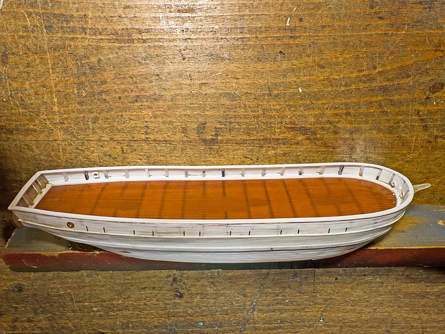
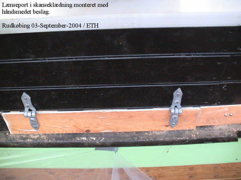
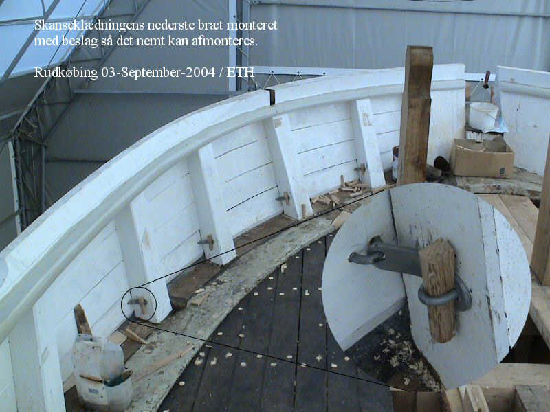
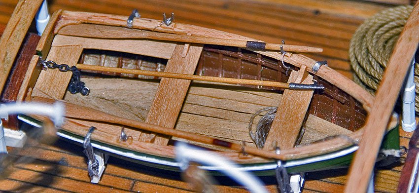
Thanks again for your moral support, verbal and via the buttons ! ****************************************************************** A Mystery Resolved When constructing the hull of the Rahschlup, it bugged me that there was no obvious way to free the deck quickly from larger amounts of water taken over in bad weather. The Jacht/Jagt-type vessels often have a gap between the covering board and lowest bulwark plank, but on all illustrations of Rahschlup-type vessels no such gap was visible. Freeing ports, as on modern ships came into use only later and the lead-lined gutters would not be sufficient. Then I scanned through the images of the restoration project (https://www.jensine.dk, but the link does not seem to work at the moment) for the Danish Jagt JENSINE (1852) for a different reason and two images caught my eye: They show that sections of the lowest bulwark plank are actually hinged and can swing out. In calm weather they are secured with latches. Subsequently, I noticed similar features on other restored vessels. I am not sure that this is an ideal solution for securing, as the wedges would need to be removed individually and kept for re-use. Also, the latch is attached to the plank section and could get caught between the plank and the covering board. I think a solution with a hook fastened to the stanchion that engages a staple in the plank would be a better solution. How to represent such parts now in 1/160? Producing the hinges will be relatively simple, although they will be tiny, but the hooks is another matter. For the hinges I took 2 mm long lengths of 0.1 mm tinned copper wire that was squeezed flat on my repurposed watchmaker jewelling tool to a predetermined thickness. These jewelling tools have a micro-meter stop that allows to very precisely set the distance between the anvil and the stamp. By squeezing, the ends of the flattened wire become rounded, which suited well the purpose. There was also a slight dimple in the anvil from the turning, which resulted in a slight boss in the middle of the strip to simulate the actual hinging mechanism. The ‘hinges’ were glued on with varnish. The latches are another matter and had to be much simplified. A double L-shape was bent into a short length of 0.1 mm tinned copper wire to simulate the hook and then one end was squeezed flat to represent the part that would have been screwed to the bulwark. These tiny pieces were then glued with varnish to the lowest bulwark planks and to the bulwark stanchion. I decided to make only every second space between the bulwarks ‘swinging out’ and scored the lowest plank on the outside lightly to mark these sections. Unfortunately, these parts are so tiny, that they are almost impossible to photograph, unless I use my macro-photography set-up and then they would probably look discouragingly crude … To be continued …
-
Thanks for your kind words. I am actually planning a miniature version in 1:160 scale for my current project.
-
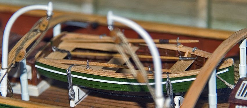
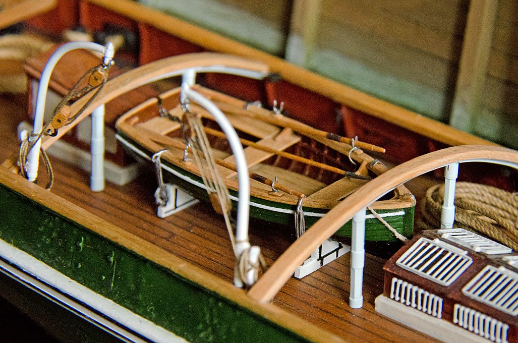
Had this booklet for many years, don’t remember when I bought it during my repeated visits to the NMM, when it was still intact. In the mid-1990s I used the half-model as a template for the dinghy for my late 1860s steam-tug project in 1:60 scale - mainly because the strakes were developed, which came very handy at this scale. The model was constructed over a wooden plug with bent wooden frames and strakes made from bakelite paper. Transom and all internal timbering again are wood. Unfortunately the 5 cm long model is a bit obscured by the tug‘s deck fittings.
-
How were these guns trained? I know larger one were put onto curved tracks, but in SE England coastal valley, there doesn’t seem to be much space. Or were they rotated? But then one would need some lateral supports on the rail-carriage to take up the recoil forces. Nice paint job, btw.
-
Swift 1805 waterline
wefalck replied to petehay's topic in Painting, finishing and weathering products and techniques
If you want to paint the hull, you probably have to stay with some organic solvent-based paint, such as oil-paint or enamels. I don’t know the composition of Minwax, but the name seems to indicate something waxy or oily. -
It becomes difficult to distinguish modell and original …
-
Good 'Hobby Quality' Metal Lathes
wefalck replied to tmj's topic in Modeling tools and Workshop Equipment
@druxey, being the lucky owner of a Lorch, Schmidt & Co. WW-pattern watchmaker’s lathe, probably from the 1950s, with the extremely rare screwcutting attachment, I haven’t actively looked for those thread-chasing attachments anymore for years … as the generation of the original owners slowly dies out, they may appear on the market more frequently now. -
Good 'Hobby Quality' Metal Lathes
wefalck replied to tmj's topic in Modeling tools and Workshop Equipment
Precision and surface quality depends on many factors. Vibration is a problem and a lot of mass helps to keep it down, which is why toolroom lathes are heavy, several hundred kg or pounds. On such lathes you can minute precision parts, we are talking about tolerances in the range of 1/100 of a mm or better. Slides are scraped (or precision ground) and lead-screws are ground snd lapped for smooth operation and uniformity along the whole length of travel. For shipmodelling this not normally needed. Tolerances in the order of 1/20 mm (the minor division on most dials) is sufficient. Most of our parts are quite short and we work on stock held in a chuck or collet. Re-chucking to work on the other end of a part is less frequently needed, which removes concentricity issues. Even with a lower quality lathe thus good results can be achieved. For hobby work a bench-lathe is perfectly adequate, we don’t need heavy floorstanding toolroom-lathes. -
Good 'Hobby Quality' Metal Lathes
wefalck replied to tmj's topic in Modeling tools and Workshop Equipment
Just to clarify a misnomer: the UNIMAT is not a jeweller‘s (American for watchmaker) lathe. It is designed as a modeller‘s lathe. It just doesn’t have the precision of a real one. I don’t know, whether this applies to all versions, but it’s motor is notorious for giving up prematurely … -
If it's black on white, heat-transfer paper for laser-printers could be another route. Play around with the lettering on a graphics program until you are happy with it, print it onto the transfer-paper and iron it on. The paint underneath, of course, has to be sufficiently heat-resistant. In principle it works also with ordinary printer paper, but the heat-transfer paper gives off the toner completely, while printer paper always retains some.
- 383 replies
-
- 5
-

-

-
- Billy
- sternwheeler
- (and 1 more)
-
Good 'Hobby Quality' Metal Lathes
wefalck replied to tmj's topic in Modeling tools and Workshop Equipment
Oh yes, you are right. I had been thinking of lead-screws and changewheels, but the UNIMAT one was of the cartridge-type, where are cartridge with a master-thread that is screwed to the lathe spindle and there is a follower on a bar behind the lathe that engages with the master-thread and moves the cutting tool along. It the kind you would find mainly on lathes for the optical industry, where short, but very precise threads are needed. Here is a picture from www.lathes.uk.co: In nearly 30 years of scanning the Internet for lathe attachments and the likes, I have seen may be two units for sale. Ah, and one more important point to watch out, when buying a lathe: ideally, you want to have zero-ing dials on the handwheels. That makes turning to pre-defined points without calculating so much easier. On the hand, once you have a lathe, you can perhaps retro-fit them yourself - a lathe is a self-replicating tool.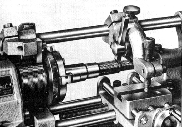
-
Good 'Hobby Quality' Metal Lathes
wefalck replied to tmj's topic in Modeling tools and Workshop Equipment
Remember that double-slotted collets, such as the ER-type are designed for holding tools or round stock. The material has to go through the whole length of the collet or nearly so. Pieces of less than half the length of the collet cannot be securely clamped, as tightening the collet has the tendency to squeeze the part out of the collet ... there is also the risk of damaging the collet in this way. -
Perhaps neither, but sheet-metal ? At that time die-pressed semi-relief sheet-metal ads were common. The design was added in form of decals and then burnt-in, as was done for porcelain.
- 383 replies
-
- 5
-
-
-
- Billy
- sternwheeler
- (and 1 more)
-
Well, this slot under the lowest bulwark-plank seems to have common feature on smaller vessels all around the Baltic and Scandinavia, particularly, when the water-way was more or less flush with the deck. I have seen many original vessels and models like this. Another option would have been hinged freeing ports that were locked in fine weather with a latch. The freeing ports are essentially the lowest bulwark-plank divided into sections that are individually hinged. I will discuss this particular feature in the forthcoming post on my building-log for a Rahschlup. In the 1870s seaboots commonly would not have been rubber although such boots seem to have been manufactured since the middle of the century. They were oiled leather, above knee-length and had either wooden or heavy leather soles with hob-nails. In the Arctic, rubber-boots would have been impractical, as the rubber becomes stiff and brittle, prone to cracking and also conducts heat much better than leather - cold feet guaranteed in spite of heavy woolen socks.
- 63 replies
-
- 2
-
-
- Northwest passage
- Norway.
- (and 2 more)
-
Good 'Hobby Quality' Metal Lathes
wefalck replied to tmj's topic in Modeling tools and Workshop Equipment
A topic one can discuss for hours and there are already several threads on this topic here on the forum. As @toolmaker said, the first thing to do is to make a list of the enveloppe you think you will need and of the capabilities required - then go for a lathe about twice the size. One always underestimates the distance between centres and swing needed (BTW, in the US the 'swing', i.e. the maximum diameter of parts is given, while in Europe it is the centre height, i.e. the height above the bed or the radius!). The next key question is, whether you think that one day you may want to cut threads: neither old Unimat nor the Taig doesn't have this capability ex-factory, but there are several suggestions for retro-fitting on the Internet; the Sherline has this as an extra to be purchased; the medium to larger PROXXON models and the the Cowells ME lathe have the capability build in; the various modern Chinese lathes have this capability, but (plastic) change-wheels may need to be purchased as an extra; classical watchmaking lathes do not need thread-cutting capability, but it was offered for some of the WW-type models (Lorch, Schmidt & Co., Wolf, Jahn & Co., Boley, Leinen, and Levin), but prices on the secondhand-market tend to be astronomical. Personally, I prefer working with collets, rather than three- or four-jaw chucks. Much safer and much better repeatability. Not all lathes have a spindle-cone to take in collets, for some so-called collet-chucks are/were available (Unimat, Proxxon). The Sherline has a spindle-cone and a limited range of collets is available, but with an adapter, standard WW-type watchmaking collets can used (available from Sherline, albeit not the same quality as the original ones). On watchmaking lathes collets are a standard feature. The 'feel' while working with the handwheels or ball-cranks is important, how smooth are the spindles and what about backlash (the amount you can turn the wheel before a movement of the slide occurs), can it be adjusted? Related to this is how smoth the slides work and how well the adjustment via gib-strips work. These features can vary from individual lathe to individual lathe. For me these are crucial features to achieve good results. Another question to consider is, whether one has the space for a permanent set-up or has to move the lathe into storage after use. In the latter case, the Chinese and larger PROXXON lathes are probably out, because they tend to be too large and heavy. The old-time Unimat came with a nice storage case, as did normally all watchmaking lathes. Otherwise, the Sherline and Taig seem to be quite mobile. And one more thing to consider: the cost of (quite essential) accessories, such as chucks, collets, tooling etc. can be as high as the basic lathe. BTW, engine and watchmaking lathes in their 'modern' form have been around since the 1870s to 1880s, not only since the 1920s. Strangely enough many watchmakers/-repairers today still prefer to work with handgravers rather than sliderests with toolbits (as on engine lathes) - this works for the generally short workpieces they need, but making multiple parts to the same dimensions with this method is a pain unless you are well-practiced. The handgraver together with a so-called T-rest (inexplicably expensive attachment to the Sherline ...) is excellent for shaping parts such as bells. Another point: Babbitt-bearings to the best of my knowledge were never used on such small machine tools. They were not suited to the high speeds at which these machines commonly run (typically between 1000 and 5000 rpm) and probably would not be precise enough. Cheaper machines originally used lapped bronze cone-bearings in which hard steel spindles ran, while the high-end watchmaking lathes have glass-hard steel cone-bearings in which glass-hard steel spindles run. Today model-engineering lathes usually have either a combination of radial and axial ball-bearings or taper roller-bearings that take up both, axial and radial loads. -
I noticed this feature on the bridges of 'modern' (from my point of view) ships, but never thought about their purpose and function. Thanks for the explanation, makes perfect sense to use the Venturi-effect for deflecting the air-stream.
- 492 replies
-
- 3
-
-
- minesweeper
- Cape
- (and 1 more)
-
Very French looking crowd indeed and the scene comes together 👍🏻 Talking about moustaches, while they give some of the characters their 'Frenchness', I thought since Ypres 1915 big moustaches were against the regulations designed to fit gas-masks tightly, which is why post-war big moustaches went out of fashion.
-
You made me blush ... Anyway, your paint samples above seem to be extemely expensive. I don't know anything about artmaterial prices in the USA, but here in Europe I would probably not want to pay more than something in the order of 10€. Watch out for 'study' acrylics, that tend to be cheaper, though the pigment may not have been as finely ground as for the top-notch paints - but that is good enough for modelling. Her colour-scheme was already a bit outdated at the time, as in the last quarter of the 19th century black with some white trimmings began to prevail. Bevor, it was common to have coloured hulls, mainly green and blue, besides black, but the wales were often scraped and oiled, and acompanied by strakes in white, sometimes red, or on black hulls in green or blue - at least over here in Europe. Norway may have retained the colourful schemes for longer to brighten the short winter days 😉
-
... but forbidden today, I believe, because it leaves also a lot of broken corals behind, which take decades to re-grow.
-
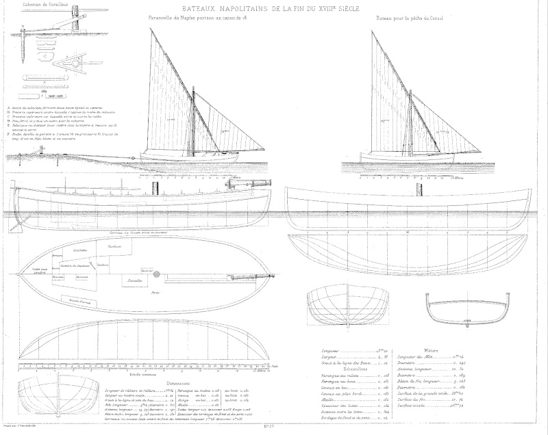
It is not a boat from the Adriatic, but rather from the coast of Campania down to Sicily (as is written on the box). The kit seems to be based on a Napoletan paranzella, plate 27 of Paris' 'Souvenirs de la Marine'. More information on these boats from the western coast of Italy can be found (p. 164-167) in this book: BELLABARBA, P., GUERRERI, E. (2003): Vele italiane della costa occidentale dal Medioevo al Novecento.- 277 p., Milano (Editore Ulrico Hoepli).
-
Absolutely - getting a cohesive colour 'mood' is not easy, preventing individual figures or props from sticking out visually 👍🏻
-
I am not an engineer, but I have a bit of an engineer's mind and my natural tendency would be to work off drawings and measurements taken off drawings. However, I realised that 'as built' is never 'as drawn' - and was never so in the world of real ship building. So it is a good idea to fit new pieces in situ to parts already existing. I kind of learned this, when I was working together with professional builders on renovating our house. They never cut wood according to the drawings, but always took the real measurements from the parts already in place. Having said that, I think my strategy would have been to first build the breastwork structure with its stanchions and rails and then fit the decorative lattices into the resulting spaces ...
- 2,699 replies
-
- 5
-
-
-
- heller
- soleil royal
- (and 9 more)
