


wefalck
-
Posts
6,652 -
Joined
-
Last visited
Content Type
Profiles
Forums
Gallery
Events
Everything posted by wefalck
-
 Me too, I love those frilly ventilation grilles 👍🏻 I have been following on/off that YouTube channel on rebuilding and fitting out the TALLY HO, that probybly most of you are aware of, and recalling how they were struggling to get all the furniture etc. to fit makes you appreciate how difficult this is in a model ...
 -
This is what I tried to imply with my previous post. However, in the case of cogs, which was the subject of the original post, the scope is narrowed largely to northern Europe, so cogs indeed seem to have ventured into the Mediterranean (e.g. in the context of transporting Crusaders). Geologists have deconvoluted (or at least tried to) the different ice-flows during the different glaciations, so that we roughly know where around the northern European coast which kind of boulders from which origin can be found. If I now find in a wreck boulders of different rock species, I can to some degree locate the areas where the crew had picked up these boulders or in other words the 'ports of call' - this is assuming that no transfer of ballast has occurred between ships. There has been also for centuries, if not millenia, an extensive trade in stones of particular properties. For instance, mill and grindstones from sandstone deposits on Bornholm or the Rhineland can be found all over Europe. The rough-cut stones may have been transported as ballast or finished products partially replaced ballast in ships loaded with other products. Mapping such trade-routes is a specialised field in archaeology and history, drawing on geological, petrographic and mineralogical expertise.
-
In fact, some of the boulders that may have been used as ballast can be traced by geologists without any scientific instruments to very specific locations in Scandinavia. However, this does not mean that they have been picked up there, because these boulders have been transported by the glaciers during the various ice-ages over hundreds or thousands of kilometers to what are now the southern shores of the Baltic. With the aid of trace-element analysis today, geologists (and criminologists) can now trace many rocks to very precise locations around the world. In this way we don't necessarily know the origin of a wreck, but we know, where it has loaded ballast.
-
Really ? I have only seen such 5C collets and other larger types. Schaublin at some stage offered them on demand I think, but don't ask about prices ...
-
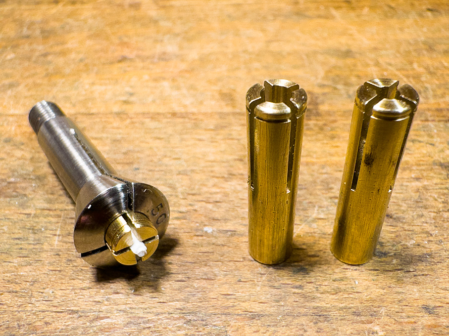
Hopefully not too many, Pat ! ****************************** Another small toolmaking digression One of the great advantages of watchmaker’s lathes is the multitude of work-holding options/spindle tooling. There are collets and chucks of many different sizes and types. One type, however, never seems to have been made and this is collets with square holes. In a way it is understandable, as making exactly centric square holes with the technology available 50+ years ago, would have been quite a challenge and expensive. Today with EDM that would not be a problem anymore. It seems that watchmakers actually had little need for them and when they needed to chuck up a winding stem at the square end, they would have used a so-called 8-screw chuck, which however, is worse to set up than a four-jaw independent chuck. I expect to have to work at the ends of some square section materials soon. While I have also a centric four-jaw chuck for the lathe, it does not fit onto micro-mill and for parts of less than 2 mm edge length it is not very precise. Working on such small parts in a chuck does not feel very safe either. Therefore, I decided to finally implement and idea that I have been tossing about for years: square insert collets. A standard fitting for watchmaker’s lathes is a set of brass insert collets that are used to hold delicate objects, such as small screws by their threads. They fit into a 5.0 mm collet and have three slots to ensure concentricity. The idea was to make collets with two cross-wise slots (like the cheapo brass collets you can buy for handheld drills) and a bore in the centre. By combining an appropriate slot width with an appropriate bore, you can make square stock fit diagonally into the collet and centre it exactly. I worked out the geometry needed for 1 mm, 1.5 mm and 2 mm square stock/parts respectively. The other dimensions were taken from the existing insert collets, i.e. the diameter of 5 mm and the length of 20 mm. Blanks were turned up from some quality old brass rod, bored from the back with 2.5 mm and threaded M3 for depth stops to made at some later stage, if needed. The blanks then were turned around and drilled 1.1, 1.7 and 2.4 mm respectively for the three collet sizes. A shallow groove turned in facilitates the extraction from the main collet. The parts then were transferred to the mill and set up in a vice with a square collet block for slotting exactly across the centre. They were all slotted 0.5 mm. A test turn with a 1 mm square polystyrene rod shows that this works very well. Size 1 mm, 1.5 mm and 2 mm square insert collets for 5 mm watchmaker’s lathe collet. Back to the Rahschlup now.
-
Fair enough, forget, what I said. I fully understand that version 7 is enough.
-
I don't want you spoil your efforts, but could you make the letters in BILLY a bit bolder still? They have the right shape, but look a tad skinny. Otherwise, no one will ever know, unless they had the picture for reference ...
-
As a geologist (who received his basic university education in the geographical area of question), I would say that there are no 'ice-shattered' rocks ... On the sand vs. rock ballast, one has to make a difference between the regions: in the continental North Sea regions boulders or pebbles were difficult to come by, while in the Baltic region pure sand is more difficult to find. Sand has the risk of clogging up pumps ... In the harbours in the region in question regulations for where to discharge (sand) ballast were put into place quite early, as 'wild' discharges near the quays led to sanding-up issues at a time, where dredging was in its infancy or no means were available at all. Pebble and boulders on the other hand were valuable building materials for e.g. foundations or paving.
-
It would be useful to know in what part of the world the originator of the question lives in ...
-
As always, the region you are looking at is important re. the availability of rocks. In fact, most of the southern Baltic and adjacent North Sea areas, where cogs originated from and in which they traded are areas of glacial moraines with little outcrop of bedrock. What you would find there are so-called erratic blocks, well-rounded due to glacier and melt-water transport. These would also be the areas of aboundant rounded pebbles on the beaches. The rock-types would be mainly granites and gneisses. There are sandstone and limestone outcrops on the Baltic islands of Gotland and Bornholm. Sweden and Finland have exposed outcrops of granites. In Denmark and Northern Germany there are only a couple of outcrops of limestone. Along the coasts of the British Islands and France, one would find a greater variety in rocks along the exposed coastal cliffs. Apart from those erractic blocks and the pebbles picked up on the beaches or when ploughing fields, there has been for centuries a trade in cut stone-slabs from Scandinavia to Denmark and Northern Germany as ballast. These were used in construction and to pave sidewalks. On the return trips the ships were ballasted with sand instead. However, I don't know, when this kind of trade started. Concerning sizes, in those moraines you can find anything from car-sized blocks to gravel and sand. I gather people used what they found and what could be man-handled - keep in mind that a block of rock weighs about 2.5 to 3 times as much as an equally sized glass of beer ...
-
Well, these Vallejo guys started off supplying the (Spanish) art world, so I would suppose that they do know a bit about brushing paint ... I always struggle brushing on acrylics, but you achieved a really good finish!
-
I agree, every time a similar product appears from the East on our markets we talk about 'pirates'. Strictly speaking, one can only talk about it, if the design or lable is legally protected, e.g. by a patent or a trade-mark. I don't know, whether the 'Cool-Tool' designs of these modular machines (either in plastic or in metal) are (still) protected in any way. Fact is, that these products coming out of Austria, first appeared on the market in the late 1980s the latest. I recall having seen them in a shop in around 1988, when living in the UK. These Chines copies appear on our markets for the last few years, so a good 40 years later. Whether these are legal copies of an unprotected design or of a pirated design I can't really say. So perhaps, I shouldn't have used the P-word. On the other hand, there is no comparable European or US American product ...
-
Unlike my wife, I don't really believe in telepathy, but it is weird that yesterday afternoon I was thinking of your work, that you hadn't been visible here for a long time, and that I should perhaps prompt you with a post here ... glad to hear that you are back - considering that most of us are 65+ plus one has certain apprehensions health-wise.
-
Looking for ideas for work area
wefalck replied to Desertanimal's topic in Modeling tools and Workshop Equipment
Indeed, IKEA (kitchen) furniture gives a lot of options for 'hacks'. I built a wall-length hotel-style built-in bedroom wardobe including TV nook with them and something similar for a living-room with TV behind sliding doors, bookshelves and a mock fireplace from them. My workshop is built around Kalvalier(discontinued) and Billy units. At some stage IKEA did also hardboard with holes for plastic hooks which are very handy for hanging tools, but they discontinued those. However, I have attached narrow shelves above the workbench by screwing from behind into the boards using long screws. -
This is just my irrelevant opinion, but I would not have a lot of confidence into the rigidity, stiffness, and accuracy of set-ups that involve hand-held rotary tools in general. While it can be useful to have a tilting head, tramming it in exactly vertical can be a pain. However, there is no problem with side pressure in the rotary tool itself, as these are designed for that. I can very well understand that space can be an issue, which seems to make combination machines attractive, but in general, space saving is bought with time spending for set-ups.
-
HMCSS Victoria 1855 by BANYAN - 1:72
wefalck replied to BANYAN's topic in - Build logs for subjects built 1851 - 1900
Good to hear, Pat, that the intervention went well and that you are back at the project!- 1,013 replies
-
- 2
-

-

-
- gun dispatch vessel
- victoria
- (and 2 more)
-
They seem to have an on-line shop: https://shop.thecooltool.com/en/pages/design-cnc. They company is based in a small town a few km south of Vienna/Austria.
-
The mill is actually a pirated copy of a development by the original UNIMAT people in Austria, first as a sort of toy with plastic parts and then all-metal: https://thecooltool.com/produkte/unimat-ml (sorry I didn't find an English Web-page).
-
As far as I can see, these Chines benchdrills have two ball-bearings, one up and one down. One would hope that they are of the kind also rated for axial pressure. So, in principle no problems with side loads. There shouldn't be a problem with using the benchdrill for light milling operations, as long as the quill is not run out. If you lock the quill in the up position with the thumb-screw provided, all the side thrust will be taken up by the bearings and no angular deflection occurs. One should note, that Jacobs drill-chucks are not designed for side loads. As I said earlier, you should look for the version with an ES collet chuck. These drill-chucks are not very precise anyway. ES collets nominally only go down to 0.5 mm minimum diameter. If you want to drill smaller holes, you need to look for drills with thicker shafts. There are the watchmakers HSS spiral drills with 1 mm that go down to 0.1 mm diameter. These would be my personal choice, but they are not so easy to find these days. Another option are the ubiquitous carbide drills with 3 mm or 1/8" shaft, but they are too delicate for my taste.
-
Perhaps then you should look at the drill-presses that these guys and others are making/selling: Go for the ES-collet version. There seem to be a lot of offers at various prices around the Internet. I think here on the forum somewhere there is also a review. I have had the predecessor of the current PROXXON bench-drill since the early 1980s and it still serves me well.

-
Good 'Hobby Quality' Metal Lathes
wefalck replied to tmj's topic in Modeling tools and Workshop Equipment
Well, drilling a 0.8 mm (my typical nail shaft diameter) through hole into a 20 mm thick piece of steel would be a bit of challenge in itself ... could do it on the lathe into a piece of round steel. I don't have an arbor-press, so I would need to do the pressing on a vice. I have experimented with all sorts of carbide tooling, but as I don't have a really good way to sharpen them, I tend to use it only for rough work. The onyl exception is the so-called Swiss Lathe tooling, brazed carbide bits with a shaft of 4 mm x 4 mm that are used on automatic turning machines. Otherwise, I have come back to purpose-ground HSS tool-bits. In fact, my most-used bit for miniature work is one that is ground like a grooving tool with a front cutting edge exactly 0.4 mm wide. It cuts left and right, so I can work on parts from both sides without changing the tool. I have two versions, one with 0° cutting angle for brass and one with about 5° for both steel, aluminium and acrylics. I know, this is not the most efficient tool geometry, but I am not in 'production'. Still have to finish the tool-grinder I started to build ... -
To me it actually looks like a reasonably well-engineered piece with a design based on stock-material and -parts. However, looking at the technical specs, I think a spindle speed of only 2000 rpm is a bit on the low side. I would rather like to have something in the order of 5000 or for wood even higher. Obviously, I don't know the thinking of manufacturer behind not providing a T-slotted table. However, in modern manufacturing such tables are typically replaced by 'tool-plates', i.e. slabs of steel or aluminium with patterns of threaded holes for various types of fasteners. Such plates are also useful for use with excentric low-profile clamping kits (such as the 'mitee-bites'). One could drill holes at suitable locations into the table, thread them and then clamp a toolmakers vice onto it. For larger parts, two-part vices are useful. I didn't compare the enveloppes, but I have the feeling the PROXXON MF70 might be a better choice as a mill, but it does not have the quill for drilling.
-
The question would be, whether they really went to the trouble of cooking on relatively short passages in the North Sea or around the Bay of Biscay etc. Given the rough seas that pervail usually in these areas, this would be a considerable fire risk. I am not an expert on this, but the archaeological evidence I seem to have seen points at clay or bronze pots with three little feet protruding from the bottom, that were set into(!) the fire/glowing embers in a hearth. There is archaeological evidence for brick hearths being used on slightly later cogs. This kind of arrangement is still in use in other areas around the world, for instance on dhows of the Indian Ocean.
-
Good 'Hobby Quality' Metal Lathes
wefalck replied to tmj's topic in Modeling tools and Workshop Equipment
In fact, for such tiny parts in brass, I use nails as stock. The stamping process noticeable hardende the brass. I know, many modellers are afraid of steel and some frown upon it because it may rust, but early on in my 'career' as self-taught turner, I discovered that I liked working with steel. It depends, of course, on what kind of steel you can find, some steels are very easy to turn and others are a real pain. -
Good 'Hobby Quality' Metal Lathes
wefalck replied to tmj's topic in Modeling tools and Workshop Equipment
I have made myself adjustable stops for the slides. Once you hit the desired diameter on a short length, you set the stop and then cut to the stop in subsequent steps. On my watchmakers lathe I can machine 0.3 mm diameter belaying pins from steel. Most brass I have access to is too soft for this. Shorter pieces I can machine down to 0.1 mm diameter and my collets go down to 0.2 mm. However, mass-fabrication of such parts is difficult and nerve-wrecking ...
