

piratepete007
-
Posts
512 -
Joined
-
Last visited
Content Type
Profiles
Forums
Gallery
Events
Posts posted by piratepete007
-
-
Jan, delighted to read your comments and I must clarify my earlier comment re the Druyfken and the Derfflinger.
Yes, I said they were similar but in no way meant they were from the same 'stable'. The point I was trying to make really was the high, narrow bulwarks, particularly towards the stern ! Of course the Druyfken is a 'jacht' ('yacht' in English) and that clearly makes it quite different to the Derfflinger which was itself based on historical records. That is the nature of the Euromodel design process. It was rare indeed for precise, technical build records to be kept except through artistic portraiture and so opinions will vary on what may or may not be the correct shape, etc. Admittedly the VOC [Vereenigde Oostindische Compagne or Dutch East India Company) had design criteria for the ships they built. Arguments will always continue back and forth about historical accuracy and that I do not wish to get involved in. I have the 'crew manifest' for the Druyfken full-size replica at the moment and am studying it with great interest, however accurately or not it reflects the original ship.
The bottom line is that I am enjoying the build of the Derfflinger and having been involved in quite a few other Euromodel builds, this one is delightfully different. Having said all of the above, I totally respect what you have said, Jan.
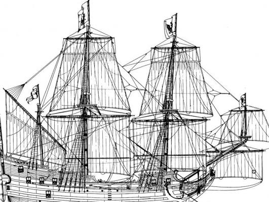
To illustrate the difficulty of interpreting what we know, read and see is encapsulated in the following excerpt I came across.....
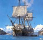
By the end of the 17th century the fluyt DERFFLINGER belonged to the fleet of Kurfuerstentum Brandenburg. In the "triangle trade" of that time she transported rum and other stuff to Africa, to buy slaves, who were then exchanged in the West Indies for sugar, which was then brought to Europe. Later she and other Brandenburg ships were used in the War of the Spanish Succession. Fleit Derfflinger was built in 1675 for the Elector of Germany Friedrich Wilhelm. The ship was named in honour of cavalry general Georg von Derfflinger, who 1675 won a Brandenburg victory in the battle of Fehrbellin against the Swedish.
The build log for the Derfflinger will continue ......
Pete
-
Bulwark Approximate Outline
Maybe this is stating the obvious but I felt it worthwhile to post this little step. The line of the upper bulwark along the ship has got me into strife before so I used the following little technique and it worked a treat.
Firstly I drilled a small hole (approx.0.75 mm but that is not significant) through the planking immediately above each frame - before the contouring arms were snapped off.
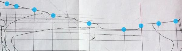
Then an outline of the upper edge was made on some ‘tracing’ paper with a soft graphite pencil and also copied onto the back surface of that paper. Using the holes as an guide, the paper was aligned over the whole surface and the outline traced onto the hull surface by a bit of careful rubbing over the pencil line

The following photo compares the two sides - before and after !

-
Prow Bulkhead (continued)
The first planking - as described in my previous post - needed to curve around past the Prow Deck bulkhead so I just worked on the principle that an excess amount of planking length is easily trimmed back to the required curve. Necessary was the formation of a fairly sharp beveled edge on the bulkhead piece to allow the planks to curve around. Also, as part of this process, alignment of the three edges (two frames and the bulkhead) in a straight line each side was important - starboard side was spot on but the port side needed approx. 1.5 mm. shaved off.
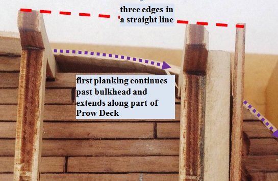
Found it difficult to ‘read’ from the drawings but in the end the forward edge was shaped to be approx. parallel to, and projecting about 3 mm. past, the sloping bulkhead. At this stage I constructed mast collars for both the Bowsprit and the Foremast. This in turn meant that the Bowsprit and Foremast lower mast needed to be constructed to enable the fitting of the mast collars.
-
Brian,
I simply cannot answer that question. I just do not know.
Pete
-
Alistair,
I must admit to having had some difficulty in understanding the bow of the Derfflinger but the drawings are good and after many hours, it proved quite simple. A lesson here in just because something is different to the normal run of the mill ship design, it need not be any more difficult. The interesting thing was that the hull shape immediately below the F'csle Deck splayed outwards just underneath to allow a wider than usual deck. The Euromodel kit is definitely not 'crap' as you described yours - and that is a pity whatever make it was. The beauty of Euromodel drawings is that in every kit there is always one full sheet devoted to a scratch build and it is on that sheet that there is so much detail the you could use. Please send whatever via a PM.
Pete
-
True Brian but surely more than just an aesthetic thing for below the water line ! I agree that the brown walnut and the white upper and lower layers will look great - but how many will throw their hands up and say it is better to 'show off' the beauty of the walnut planking. The age old question !
However, to answer your earlier question, I am definitely using white paint. Appropriate to now show off the actual ship, with the clinker planking very much evident on the upper hull.
Pete
-
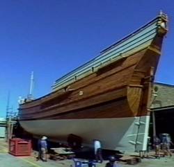
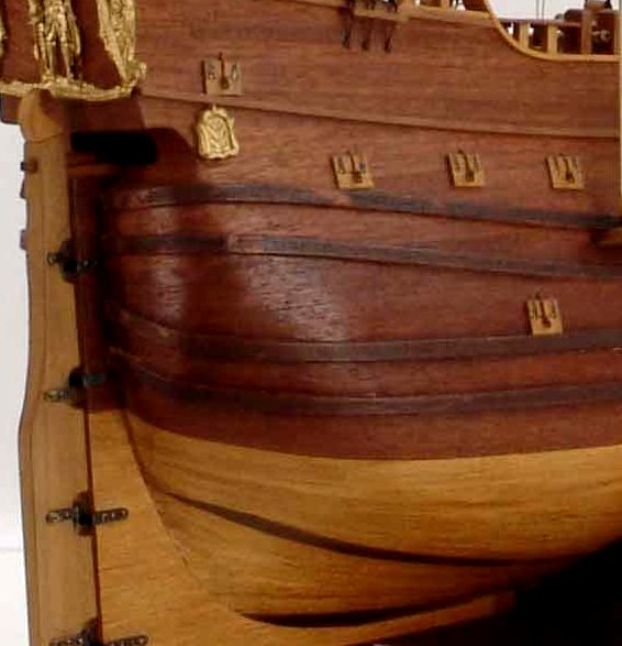
I see there was a group in Fremantle, Western Australia that in 1997-1999 built a replica of the Druyfken a 17C ship similar to the Derfflinger. The two small photos I found both suggest painting white on two areas of the hull. What I also found interesting was the clinker planking for the upper part of the hull towards the stern.

-
Brian,
'Treading water' very carefully with this Dutch ship. Familiar with English, German and French ships but not so much the Dutch although the bulkhead planking was a new one for me. I suspect you have a reason for asking so any guidance would be appreciated. To be honest, I have not given that aspect any thought and would appreciate suggestions from you and any others who feel moved to contribute.
Pete
-
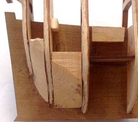
Prow Deck Bulkhead
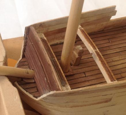
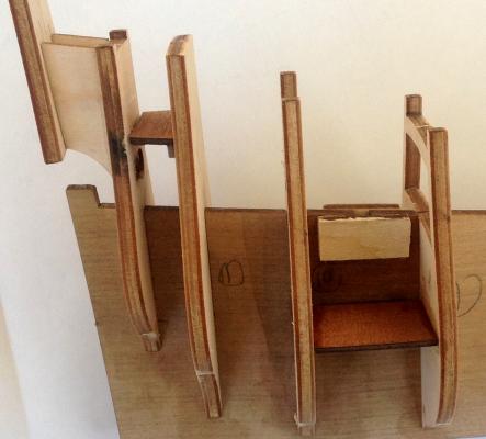
The upper first-planking on the starboard side was now carried out. The only problem here was the fragility of the completed first planking on the opposite port side whilst working on the starboard side so to avoid damaging the bulwarks, a stand was built to support the ship in an upright position. The stand allowed the stern to be slid into the back support and then ‘dropping’ the bow into the front support. So simple to make and easy to use.
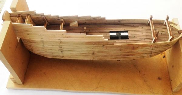
Not planning far enough ahead, I started first-planking above the Prow Deck without paying attention to the placement of the bulkhead over the deck (some evidence of this in the above photo). This planked section had to be removed but was not an issue as first planking can be ‘moved around’ and then hidden by second planking. In total, there were four bulkheads to be constructed but this was the only one that had to be constructed and fixed in position before first planking.
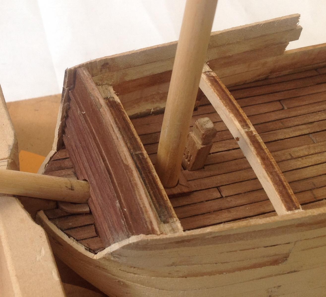
Whilst there was still room to work with, the Bowsprit Mast was constructed so that a suitable hole could be put through the Prow Deck/ Bulkhead - always forward planning to do !
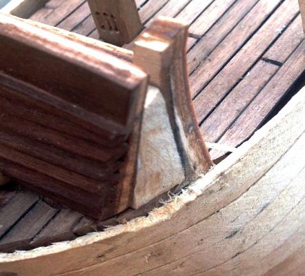
Overlapping planks (i.e. clinker) laid horizontally on the bulkhead was a method used throughout the seventeenth century on Dutch ships. The difficulty here was the curvature in these horizontal planks. Generally, builders of this ship have simply laid the bulkhead planks vertically which of course is simple but not correct. I went for the horizontal format but did not produce and curve in them - maybe much more patience could have helped. A tapered block was built to support the sloping bulkhead.
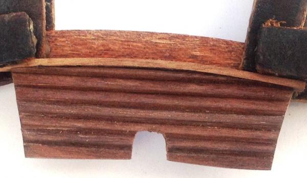
A thing I do not generally do is to use wood stain but on this bulkhead I finished up with distinctly different shades so I very lightly used some walnut stain which produced a better effect colourwise but maybe a little too dark.
Evident in this photo is the sharp curvature needed around the bulkhead edge to allow first planking to continue around and over the deck.
-
Main Deck Planking
The decking in the 17th century was usually a very light coloured timber (highly weathered, scrubbed, etc.) but there is a limit to what a kit can supply but some builders have used household bleach to good effect to lighten the timber colour. I chose not to do that.
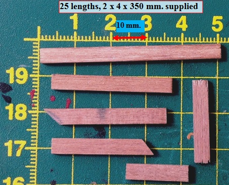
From European forests, the length of timber varied between 20-24 feet. Settling on 20 feet (240 inches), the length of planks for this ship at a 1:80 scale will be 76 mm. (to utilize the planking system mentioned below, I chose to use 84 mm.) The plan sheets show continuous planking and whilst not ideal, it is the easiest and most common thing to do. Cutting into shorter sections would have been impractical without a supporting base.
The kit provided strips of 2 x 4 x 350 mm. to plank the Main, Forecastle, Quarter and Upper Quarter decks. Past experience taught me to minimize wastage so it was a matter of selecting different lengths for all decks to minimize waste out of each 350 mm. length. The following photo shows the total waste I had after handling all those strips of planking. A close call !
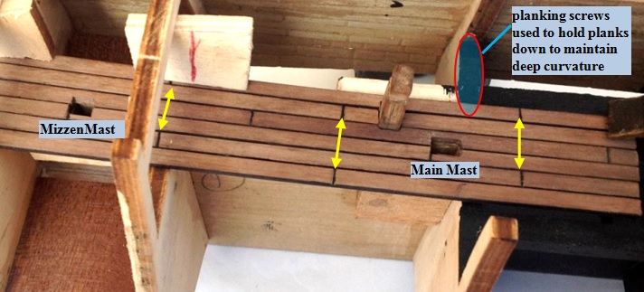
The original Euromodel instructions called for all the decking to be completed before the first planking was added. I adopted the converse of adding first planking on the port side only and then adding the deck planking - it proceeded without too much difficulty. Part of my rationale was that after first planking, some of the side supporting ‘arms’ on the frames needed to be broken away and then the deck planks applied over the broken off areas. The only cause for some concern was that by the time the longitudinal camber is coupled with the deck beam camber, there was an overall drop of 10 mm. along each side meaning that downwards tension had to be applied to the planks when fixing. Not a big problem, though. In this small ship, there was a distinct advantage of not planking the starboard side to begin with.
The gap between the plank lines in the actual ships was ‘caulked with oakum and paid with tar’, so before adding the planks, they were sanded to slightly round off the edges as well as the top surface. I marked along each side with a broad black marking pen but unlike the more usual thinner and porous planks, this 2 mm. thickness showed no signs of ‘bleeding’ from the black ink.
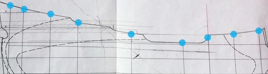
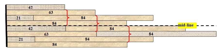
With simulated suitable end-plank joints, I produced the typical European ‘three plank shift’ planking system as shown below.
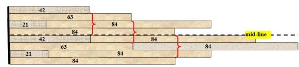
To create this style of planking, I used four different length markings on the continuous lengths – 84 mm + 21/42/63 mm lengths.
- solid vertical line (on far left) represents Frame 11 against which the planking starts
- horizontal dashed line represents the mid-line of the keel
- end-plank ‘joints’ were carefully cut into the top surface and lightly marked with a very fine (1 mm.) marking pen
- using the above figure as a starting point, the plank markings continued forwards using 84 mm. ‘lengths’
- where appropriate, cut-outs were made for the masts and bollards before laying each plank.
- small drops of PVC glue were the order of the day along the keel for the first plank along with a couple of wedges to press the plank down. A couple of drops of instant glue under the planks also helped between the hatchway opening and Frame 8 - there is a distinct curvature in the deck that needs to be maintained whilst glue is setting.

-
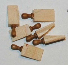
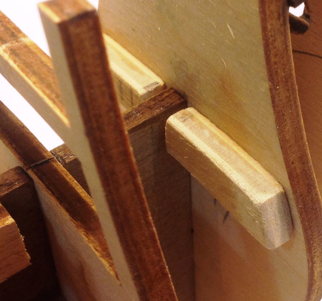
Mast Bollards
The Main Deck consisted of 2 x 4 mm. lengths of timber and the inherent strength of such thick material afforded an opportunity to do something different. I did a major amount of first planking on the port side without complementing this on the starboard side. I would not try that on a larger ship but it did allow me ample room to work on the Main Deck which by its very design was very narrow (to reduce the amount of tax due which was based on deck area). The keel did not warp at all but as a precaution I could have added some extra longitudinal support between the frames before I started on the first planking. Still, not an issue
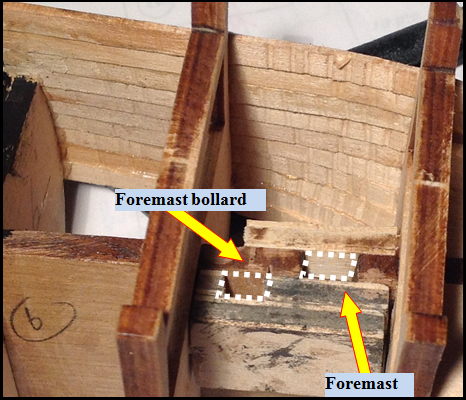
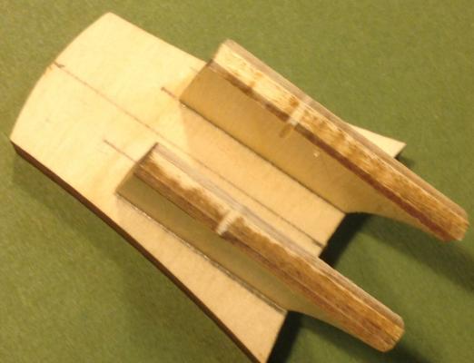
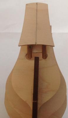
Before deck planking, support of the mast bollards under the Main Deck needed to be considered. There were three bollards - one each for the running rigging of the lower yard arm of both the Main Mast and the Foremast and one for the Mizzen Mast. The two former were to be fixed slightly off the mid-line whilst the latter was on the mid-line and could easily be fixed into the keel running directly under the Main Deck.
In the first two cases, a supporting sleeve was constructed from scrap timber that held the bollard hard up against the keel and 4 - 5 mm. aft of each mast. For the Main Mast, the bollard was fixed on the port side of the keel but for the Foremast, the bollard was fixed on the starboard.
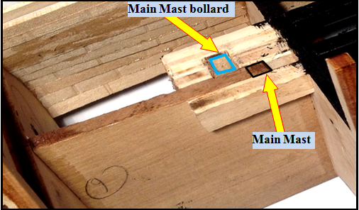
This was a classic example of my not looking far enough ahead when first adding the plywood pieces either side of the mast steps in the first place as these pieces needed to be modified to allow the correct seating/ placement of the bollards. Fortunately, I had only first-planked portion of one side of the ship, so working on the deck area was not a problem. There was a little juggling to do with the bollard sizes and the material supplied, but in the end that was not an issue. I decided to fix the bollards in place before adding the deck planking.
-
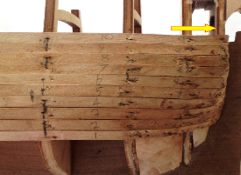
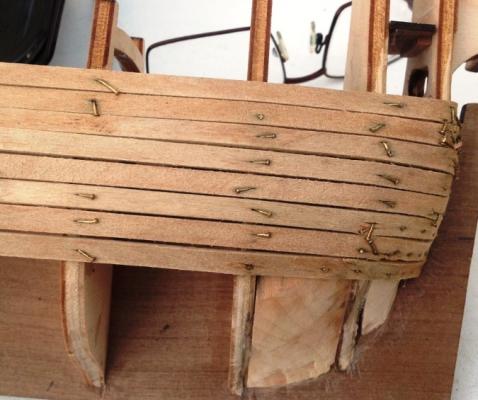
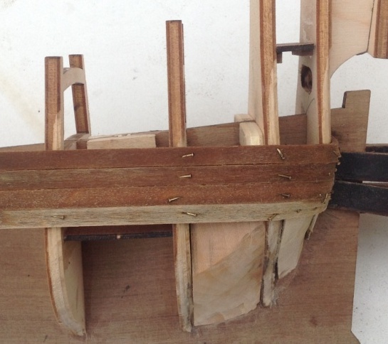
Fixing the First Ten Planks (Port Side)
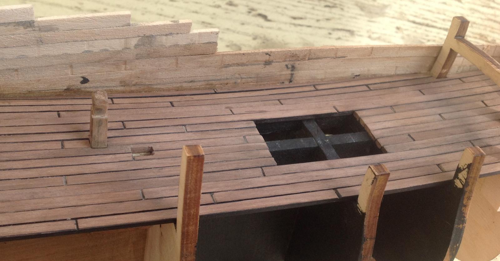
This is only a small build so I decided to plank on just the port side to begin with. With larger models, it is advisable to plank on alternate sides as the build proceeds to avoid uneven stress on the developing hull. The ten planks were finally glued back onto the frames and abutting each other with the earlier gaps now proving to be of no consequence. The work looks rough but this is largely due to the planks being fixed twice with nails. The image below shows that there is the need for one more ammonia-soaked planked to be fixed in place (yellow arrow) with a sharp bend under the transom.
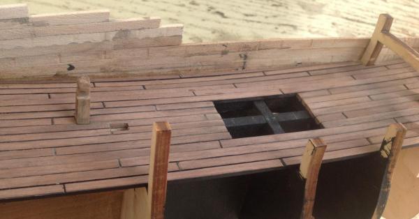
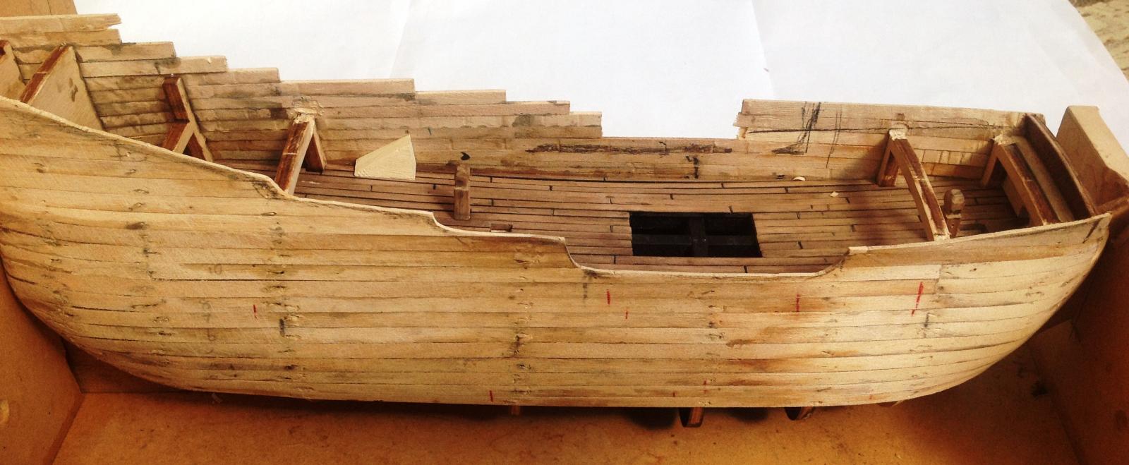
Hatchway Opening
There is a very easy method of adding a grate … no hatchway cut-out and placing the grate assembly over the solid planked deck. Using this alternative, the deck underneath would/ should be painted matt black and that is a very simplistic approach. I am reminded of a stove I built for the Friederich Wilhelm zu Pferde (another Euromodel ship) and that would never be seen so it depends on how far you wish to go with the detail.
Taking into account the dimensions of the now constructed Main Deck grate, I decided to build a support framework that would support the outer edges of the hatchway. Apart from anything else, the planks forming the deck had a distinct downward curvature along the ship and so the lateral beams at each end of the support were at the least vital to maintain the deck shape.

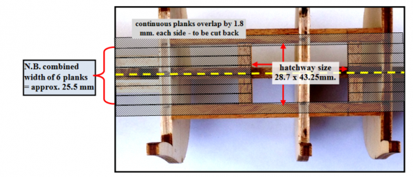
In planking the Main Deck, I cut three of the supplied 350 mm. decking strips in halves i.e. 175 mm. and these six pieces would run from Frame 11 to the edge of the hatchway. These six planks would have an overall width of 25.5 mm - the actual width of the opening was 28.7 mm. Continuing with full-length strips, there will be approx. a 1.8 mm. overhang either side. When this narrow overhang is trimmed back to the side supporting beams, the correct hatchway opening will have been formed. The grate assembly then fitted over the opening by approx. 1 mm. all around. I have included some light-shaded 'planks' just to give the overall final view.
-
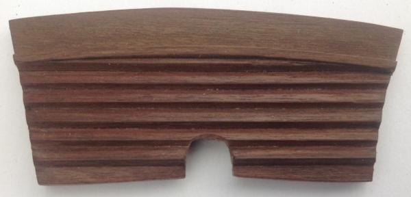
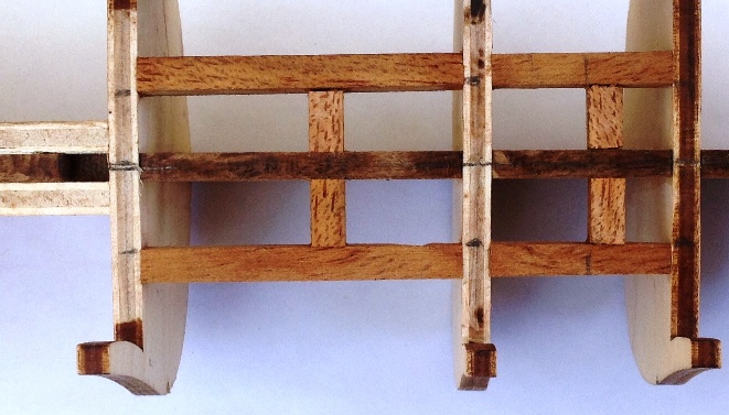
Main Deck Grate
No attempt was made to construct the Main Deck with its large hatchway until the three grate units of which it was composed had been produced. What is important to note is that the overall dimensions of the hatchway underneath in the deck will be slightly smaller than indicated in the drawings - its final dimensions were determined by the final size of the composite grate.
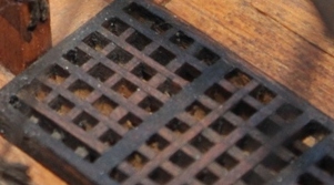
To lightly stain the grate strips for a more weathered look or leave natural timber? Two restored ships presented a distinct contrast - HMS Victory in Portsmouth with gratings painted white and a dark natural brown surround and the HMS Trincomalee in Hartlepool where the entire grate (shown in the following image) including the outer framework having a brown painted/ stained surface. In the end, there will always be a balance between historical accuracy and modellers’ preferences.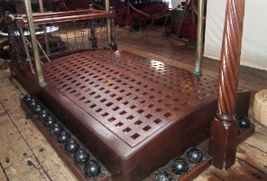
I found it is best to be prudent when assembling the grate strips to avoid using more strips than was essential. After assembling to the required size, the grates were immersed in a diluted (1:1) PVA glue, removed and the excess glue blown out by vigorously blowing over the back and front surfaces and allowing to dry. Each grate was then carefully sanded back to the required dimensions and a border surround added. The following images contrast the underside view vs the topside view. Worth remembering.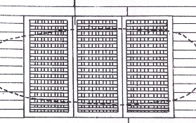
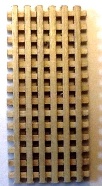
The basic approach seems to be to form a flat grate but it would be the 3 mm. thickness from the supplied strips. The next alternative would be to reduce the thickness to 2 mm. to match the supplied border material. However, in my build, I went further by producing a slight concave/ convex configuration with the final thickness being 1.8 mm. The convexity of the grate underside surface allowed it to fit better onto the Main Deck camber. My tool for doing this - a narrow vertical belt sander !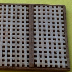
-
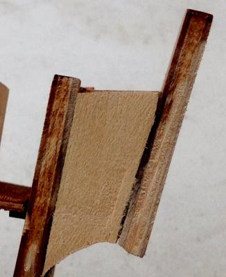
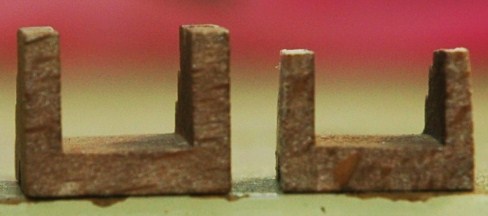
Plank Fixing, Part 1
The planks in many cases needed softening by soaking in household form of ammonia first (e.g. ‘cloudy ammonia’) - I usually leave them for approx. 5 days. With the fairly severe bending at the stern end, the softening for many planks proved essential.
As a reference, the initial strip of the first planking was positioned 78.0 mm. from the top of Frame 11 and 31.0 mm. from the top of Frame 6. Six planks were fixed above taking the planking to just below the curvature of the transom supports and a further four below. The bending around the stern was extreme but occurred quite readily after the prolonged soaking in dilute ammonia. The photo below shows some very moist planks in position.

Temporarily fixing the moist planks using a myriad of nails produced the desired shape after drying for 24 hours for the timber to dry; there were significant gaps between the planks but these would prove to be of no consequence when refixing. The planks were numbered and then removed.
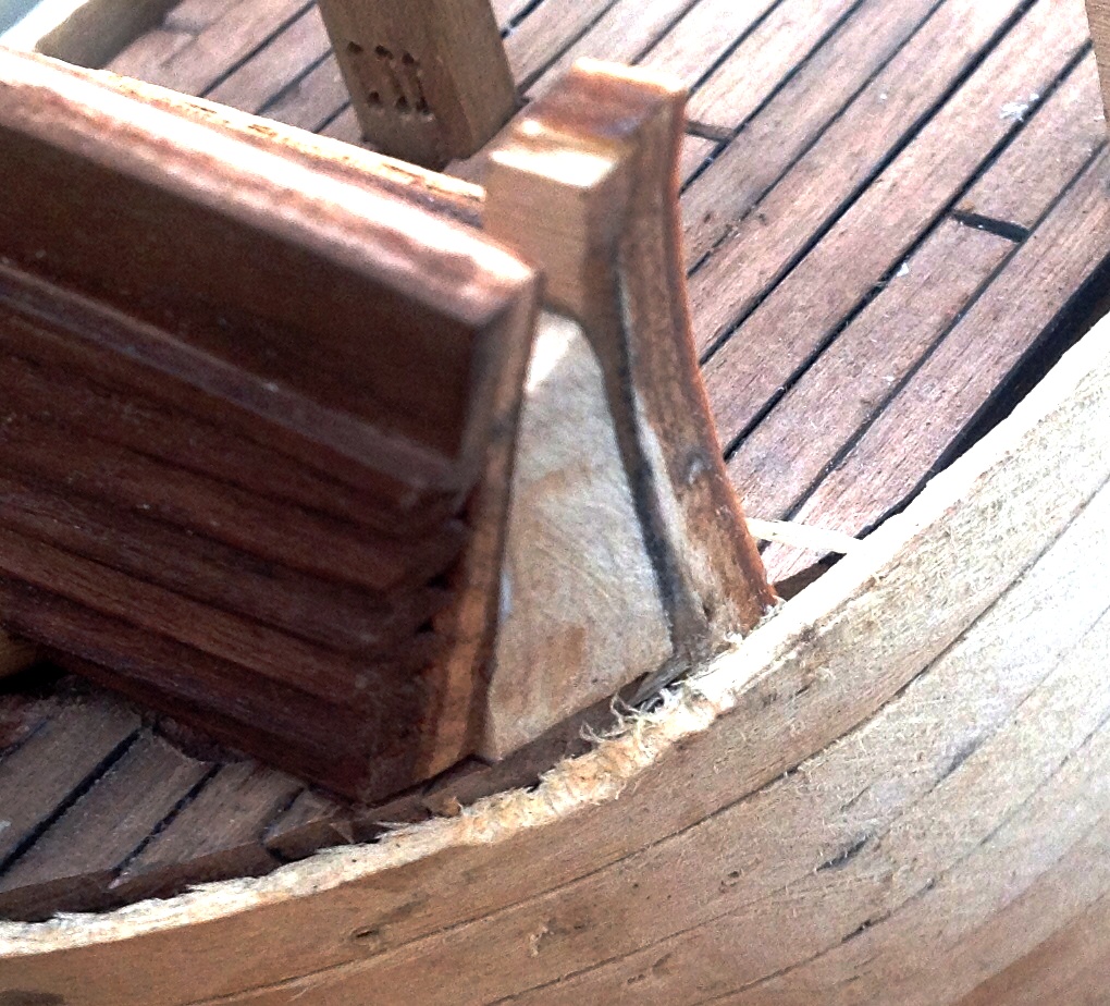
With the eleven strips dried and removed, I decided to add a shaped filler block between Frame 12 and the transom (compare the photo below with the one at the top). This would then allow the curved planking under the transom to be constructed more firmly. It also allowed me to consider the longitudinal contouring for the first planking at this point more carefully.
-
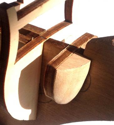
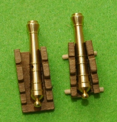
Gun Carriage Dilemma Resolved
The fluyt was principally a cargo vessel with minimum or no armament so I resolved to also minimize my build in this area. After some thought, I settled on three different approaches to the gun carriages …
- Only 2 gun assemblies are openly visible on the whole ship and they are on the open portion of the Quarter Deck. Some rationalization was called for after my earlier indecision and so just these two would be constructed with some modification, especially to produce the tapered appearance of the carriage. N.B. Quarter Deck carriages only have 4 mm. trucks supplied due to the fragile nature of the drawing-indicated 3 mm. trucks on the carriage rear.
- To add variation, 4 gun assemblies would be non-existent behind closed gunport hatches [ 2 on the Gun Battery Deck and the 2 towards the stern on the Quarter Deck]. So no construction here at all
- 10 gun assemblies (on Main Deck) would be constructed using the supplied carriages without modification.
Two initial steps on the carriage whether modified or not:
- axle tree holes (axle holes) through the 5 mm.trucks (wheels) I enlarged by drilling; the 4 mm. truck holes could not be readily enlarged without breaking the soft timber so I reduced the actual axle trees (axles) by careful sanding.
- recessed slots underneath the carriage designed to hold the wooden axle were too narrow and had to be enlarged by filing.
- a bed was constructed from some first planking. It was only after this addition that I realized that there was no height left for a quoin !!
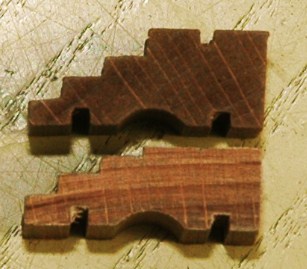
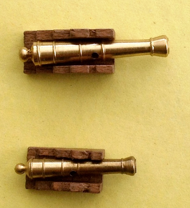
When modifying the visible carriages on the Quarter Deck:
- carriage split down the centre, sanded on a taper and rejoined producing a taper difference of 1.5 mm. from forward to rear
- front of the cheeks (sides) bevelled backwards
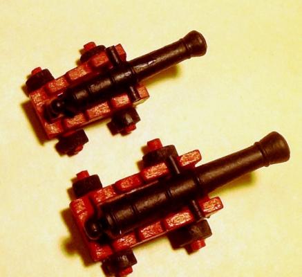
Painting was a final but significant step with a dull, dark red for the carriage itself and black for the trucks.
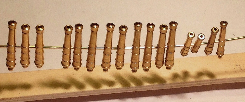
The brass cannons were supported on a wire after washing in warm water and detergent and allowed to dry. They were then painted with a matt black acrylic paint.

Trunnions were cut from the brass wire supplied and then glued in place in the cannons.
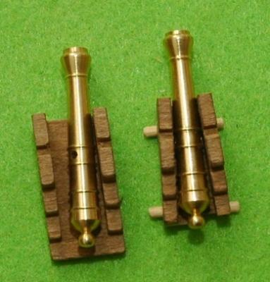
Shown here are two different examples of gun carriage assemblies - the upper one is visible (and tapered) on the Quarter Deck and the lower one is typical of those non-tapered on the Main Deck that cannot be seen.
That completes the initial carriage construction and now I must turn my attention to adding the first planking - some of the strips have been in ammonia solution for the last 7 days !
- Griffon, marktiedens, maggsl_01 and 2 others
-
 5
5
-
Brian - had given up the idea of splitting and tapering the carriage BUT your comment stimulated me into doing just that. In the middle of it at the moment and actually working out better than I thought. Tapers by 1.5 mm. which is sufficient to create the effect.
Pete
-
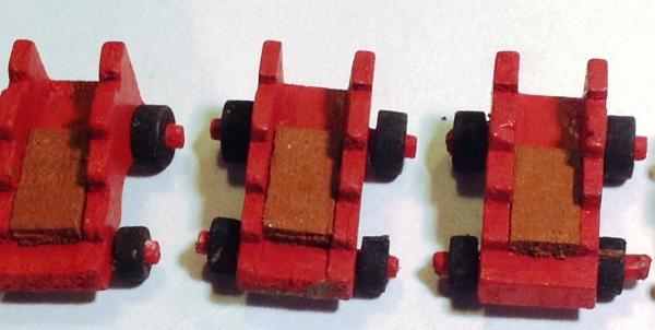
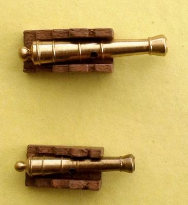
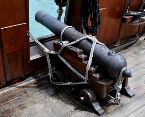
I have just looked at the drawings and the carriages supplied. Unless the carriages are individually crafted, the obvious choice is to use the ones supplied as they are. On a larger scale, there is more latitude to taper and to thin the carriages but on this scale, I have now decided to make all those gun assemblies after all. The following photo illustrates how difficult it would be to create any modifications to the supplied carriages. Not suggesting that it is impossible - just difficult. Soi there is another point in this build where the individual can exercise their patience and do some detailed work. Out of interest, there is a photo of a 17C cannon/ carriage assembly I had stored in my files from MSW but did not record the author/source. My apologies to whoever.
So it is back to the workbench to make those carriage assemblies.
Pete
-
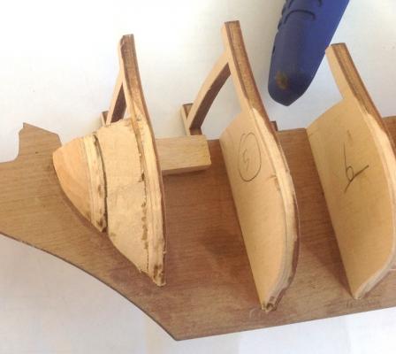
A sidestep at this stage was a consideration of the armament - necessary to determine the height of cut-outs in the first planking. The kit provides two different gun carriage lengths – 30 & 22 mm.
- Gun Deck - 2 : 30 mm. cannons/ 19 mm. carriages
- Main Deck - 10: 30 mm. cannons/ 19 mm. carriages
- Quarter Deck - 4: 22 mm. cannons/16 mm. carriages
I was then confronted with making decisions …
- Gunports covered, retracted cannons not visible and cannons not used at all.
- Gunports open, projecting cannons visible, unmodified carriages used.
- As in 2 above but with modified carriages as per the drawings.
All to often, ships are built with cannons projecting but in reality for most of the time the ship was at sea, the cannons would be retracted with the gunport closed. The sheer beauty of constructing these pieces means they should be on show ! Well... that is one way of putting it.
If following points 2 or 3 above, before doing the first planking & cutting out the gun ports, it was essential to construct the simplified gun mounts or complete gun carriages with barrels mounted (albeit, some temporarily) for the two different sized carriages to check the height of the opening above the deck. If I were to follow the pathway of carriage construction, then I had to remember that 14 out of the 16 carriage assemblies would not be visible ...
... [2 carriages on Gun Battery Deck before the Main Deck installation, 10 carriages on Main Deck before installation of the Quarter and Forecastle Decks, 2 of the 4 carriages on the Quarter Deck before the Upper Quarter Deck installation]
The decision was whether to utilize the more accurate dimension (e.g. thinner, lower, tapered cheeks) shown for the gun carriages in Plan Sheet 4, or use the carriages as supplied. The carriages differ markedly from that shown in the drawings but that is due to the difficulty in mass producing carriages with tapered sides. The following photos show the huge contrast in approach.
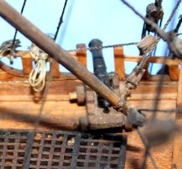
The photo on the left is from one model of the Derfflinger where the supplied carriage is used. The other photos are self-evident in what I do generally with the carriages.
Another method sometimes used is to produce supporting blocks glued onto the lower decks where the carriages are not seen. When painted black, they are generally not visible to the casual glance.
This was the first build in which I decided - I think - not to show any of the cannons projecting through the hull. (i.e. not in battle readiness). The carriages visible on the Main Deck are yet to be constructed. Having said all of the above, I may very well decide to construct all the carriages ? ?
Pete
- Landlubber Mike and mtaylor
-
2
-
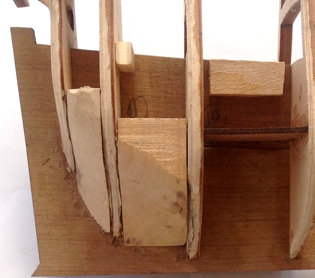
Keeping in mind that the Main Deck consisted only of a group of 2 x 4 mm. planks without any plywood underneath, it was necessary to have a support strip fixed onto the forward surface of Frame 11 for these planks.

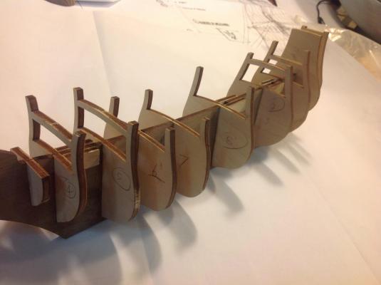
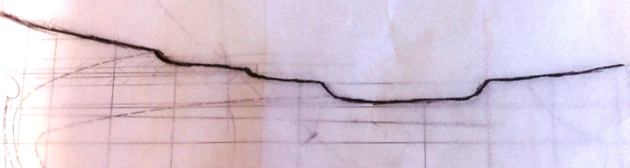
It was obvious from photos of the finished ship that the stern area required some significant bending of planks and this led me to insert two extra filler blocks per side between Frames 10 & 12. The type of timber used for filling was insignificant as long as it could be shaped. It was only when they were in place that the correct contouring could take place along with the severe bevelling on the frame edges. I took care to preserve the profile on the forward edge of each frame (the dark brown of the original frame edge can still be seen). This all had the effect of producing a fairly severe curvature at the stern. I was mindful that the stern shape would depend very much on how the frames are shaped.
The following photo shows what one builder (unknown) created and it well illustrates the severe stern curvature.

-
Brian,
When I set this up, I left out the detail such as scale but all is now remedied in the post title.
Pete
-
Hello Stockholm tar,
After reading your comment and then checking myself on the internet .... grrrr....... and .... groan ........ you are correct !!!!!~
The term 'felucca' I obtained from Euromodel and I suspect that this is a case of an Italian-English translation aberration. Poor marks to me for not checking in the first place but that is life. A little embarrassing to say the least. However, I will take it upon myself to change it to 'fluyt'
Thanks for your valued input.
Pete
-
With a long strip of wood placed longitudinally down the hull side, the frames were checked for alignment. I was pleasantly surprised that neither packing or reduction was necessary along the frame edges.The top edge (beams) contour of the frames supporting the deck was checked and I found that all were good except for Frame 7 which although it been seated in correctly in the keel and the bottom edge seemed to fit the contour of the other frames, I still needed to shave off approx. 1.2 mm. from the top edge. It was essential that there was a continuous supporting surface presented by all the beams when laying the deck as this ship is the only one without the usual Euromodel laser-cut plywood decks on which planking occurs. In this ship, all the decks are simply made from 2 x 4 mm. walnut strips.
Nothing surprising so far.
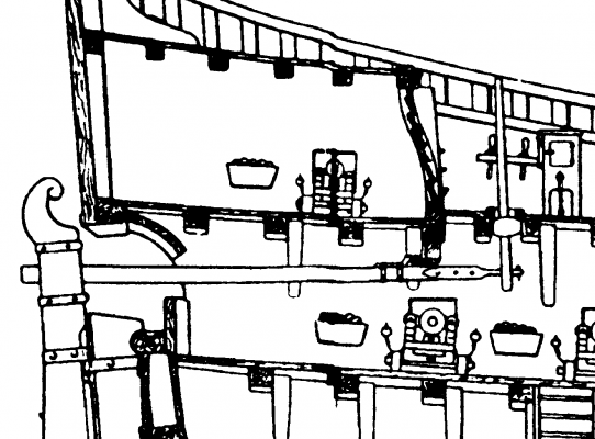
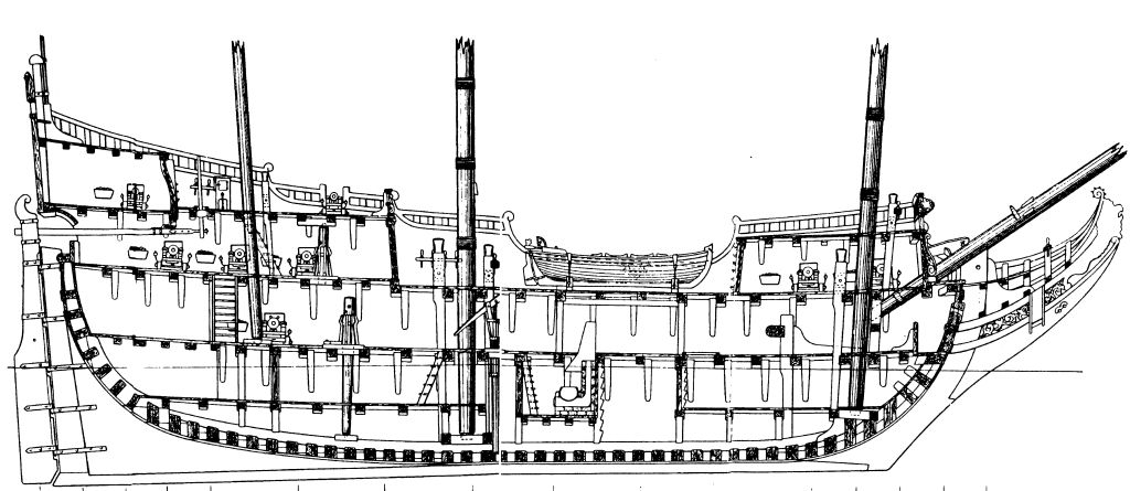
The following diagram shows some of the detail that can be found in the typical Euromodel drawings. There is ample material here for the person who wants a taste of scratch building. What is clearly evident is the Gun Battery which extends the full length of the ship and the Quarter Deck which of course is only partly visible. Nothing unusual - sure. However, Euromodel has engineered small plywood pieces to insert for these decks where it is necessary to support gun carriages. A simplification for sure but it does make the building easier (but does not prevent the ardent enthusiast in putting them in).

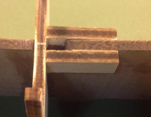
There are three laser-cut plywood pieces supplied:
2 x ’15’ used either side between Frames 9 & 10 to form part of the Battery Gun Deck
1 x ’15 bis’ used between Frames 10 & 11 to accomodate two Quarter Deck guns.
The Battery Deck pieces fitted tightly between the frames but the Quarter Deck piece was a loose fit and I had to use support strips underneath against Frame 11. Both pieces are shown in the photo.
-
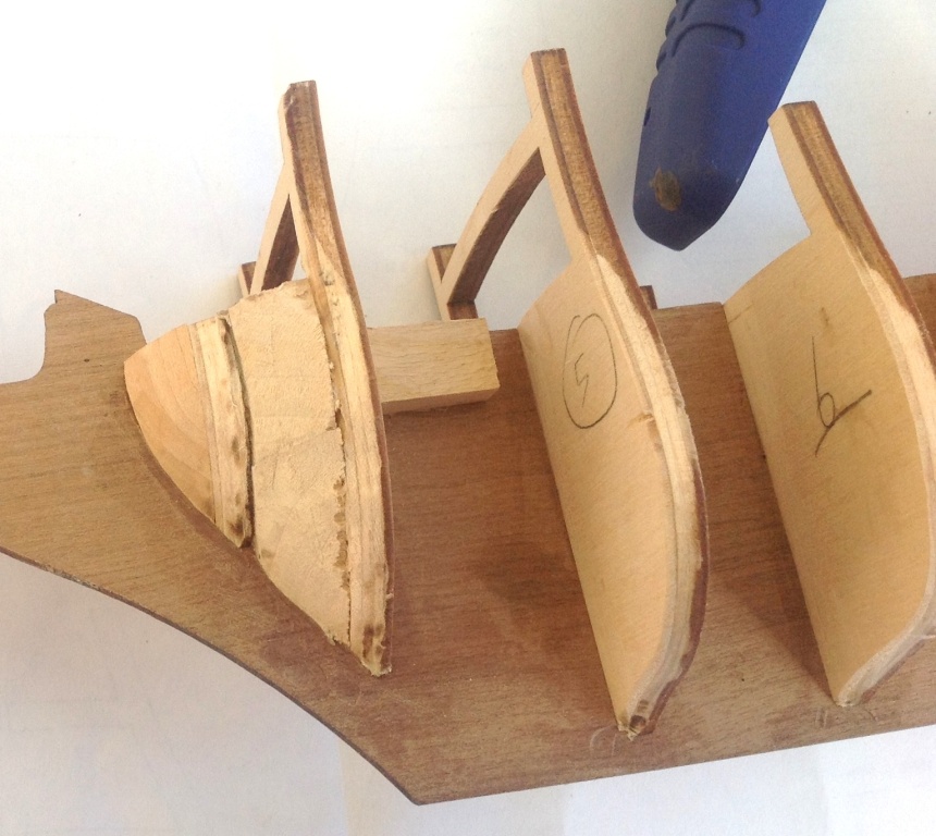
Using the supplied drawing templates, two bow filler blocks were shaped from the 10 x 20 x 80 mm. block supplied.
I also inserted EXTRA filler blocks behind these (between Frames 3 & 4). Creating the curvature on these blocks then enabled me to continue the curvature over the original filler blocks forward of Frame 3.
-
The Euromodel Defflinger is typical of their other models with high quality timber, accessories and detailed plans. OK, that's enough of the usual preamble !
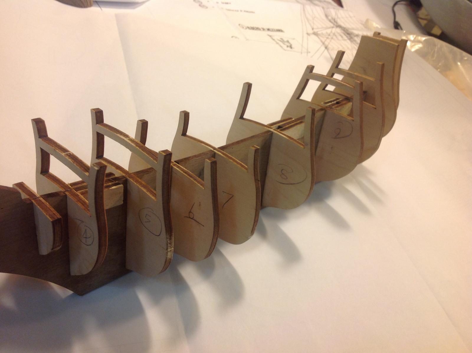
The longitudinal keel is laser cut from quality 5 mm. walnut and slotted to accept the plywood bulkheads and to form the three mast steps. The laser-cut plywood is of marine quality - unaffected by water, uniform in thickness and excellent quality.
Ten of the eleven transverse pre-cut ‘bulkheads’ were slotted into the keel as a dry run to determine which joints were too tight and which too loose. Frame 13 – the transom – was fitted afterwards. All the joints were extremely tight and a fair amount of sanding of the fitting surfaces was required. They were not fixed at this stage.
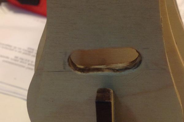
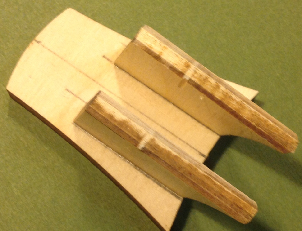
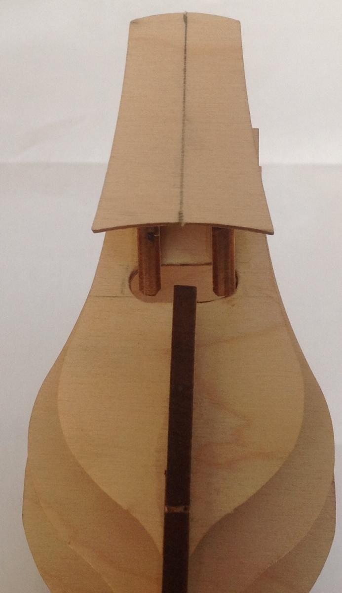
This frame required a cut-out to be made and here is the first time in this build I needed to make a decision. The method of steerage requires a tiller arm to extend inwards from the rudder through Frame 12 into the hull. This then connects to a moveable upright whipstaff that allows steerage to occur. Since the tiller will not be seen, it could be omitted thus negating the need for a cutting through Piece 12. I chose to consider the possible linkage through rudder-tiller-whipstaff and so made the cut-out.
The dimensions for the cut-out were not that critical – the drawing indicates approx. 30 mm. wide but in reality it is determined by the space between the transom supports, which is approx. 12 mm. In any case, I made it 30 mm. wide and It may be that the steerage system may not actually work but I was prepared to try it.
The frames were glued in position using PVA glue.
The main, fore and mizzen masts all have cut-out slots provided in the false keel. However, to hold the bottom of the masts in place, the mast steps had pieces of plywood glued either side of the slots to form a useful seat for the masts when inserted at a later stage.
The two supports were glued in position onto the transom.
The assembly was glued in position onto the stern side of Frame 12. To assist in the alignment/ positioning of this piece, a line was drawn to align with the keel beneath.


DERFFLINGER by piratepete007 - Euromodel - 1:80 - Dutch Fluyt
in - Kit build logs for subjects built from 1501 - 1750
Posted
Thanks for all the comments of support through PM's.
To Jan, thanks for your above comment. Again, good to have a small debate. Always raises a few further queries to investigate.
And as I said, on with the build log .....
Pete