


piratepete007
-
Posts
512 -
Joined
-
Last visited
Content Type
Profiles
Forums
Gallery
Events
Posts posted by piratepete007
-
-
Yes Vince,
Medium-sized business with a BIG heart that takes customer care INCREDIBLY SERIOUSLY.
Pete
-
Manufacturers of kits often get kicks for this or that and that is the nature of this forum. So it is good to see that people appreciate the service that Euromodel offers as shown by the above comments. Through a combination of servers in Australia and Italy, Euromodel offers a 24-hour Helpdesk and any queries can usually be responded to within 12 hours. That is the way a company should operate.
Pete
-
Hi Keith - your incredible work leaves me breathless and I must congratulate you. I keep looking at your posts and whow ! Such finess, such patience, such detail. My contributions that I keep posting on Euromodel were only ever designed to assist people make a start but all that fades into the background. I look forward to seeing the complete ship.
Pete
-
Pleased that some people are looking at what I wrote - just remember that it is far from prescriptive, just interpretive. I shudder when I look back at this stuff written so many years ago but still .......
Pete
-
John,
All kits contain a printed parts list and if you look at the Euromodel website under customer assistance for any ship, you will find a file termed 'Resource' and that also contains a parts list.
Pete
-
Thanks so much ... so obvious when you hear the real facts and the reasons behind them.
Pete
-
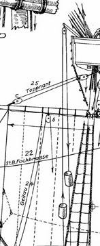
Now I might be a little lacking in knowledge in some areas of ship building so I am asking what appears to be a simple question based on the following diagram (poor quality, I know) taken from some ship plans. Viewing the image, forward in the ship is to the right. With the wheel in this position, it seems to me that the helmsman would have to have his back to the bow (?) or was it not uncommon to stand aft of the wheel on one side ? My logic is confusing me so can some sane person explain what is probably a simple answer ? Thanks.
Pete
-
Thanks Tadeusz.
Pete
-
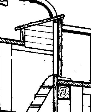
Looking for some help again ! I am working on the Euromodel Pinco Genovese and there is 'portico' (which I think translates as a 'little verandah') that is a steeply slanted 'roof' offering some protection from the weather with two doors that open outwards enabling people to enter a lower deck via a ladder. The diagram explains it a little better ... but what is the best nautical terminology for this covering ? Appreciate some assistance.
Pete
-
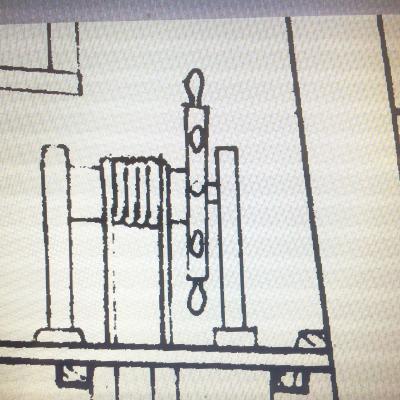
What a response - thanks especially to Tadeusz43 and Druxey for those photos and drawings. From an initial outside source that suggested stones to this variety of cylinders, buckets and what look like tied packages, the obvious focus is not on these items (which will vary anyway) but on the system itself of pulleys and ropes.
Pete
-
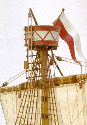
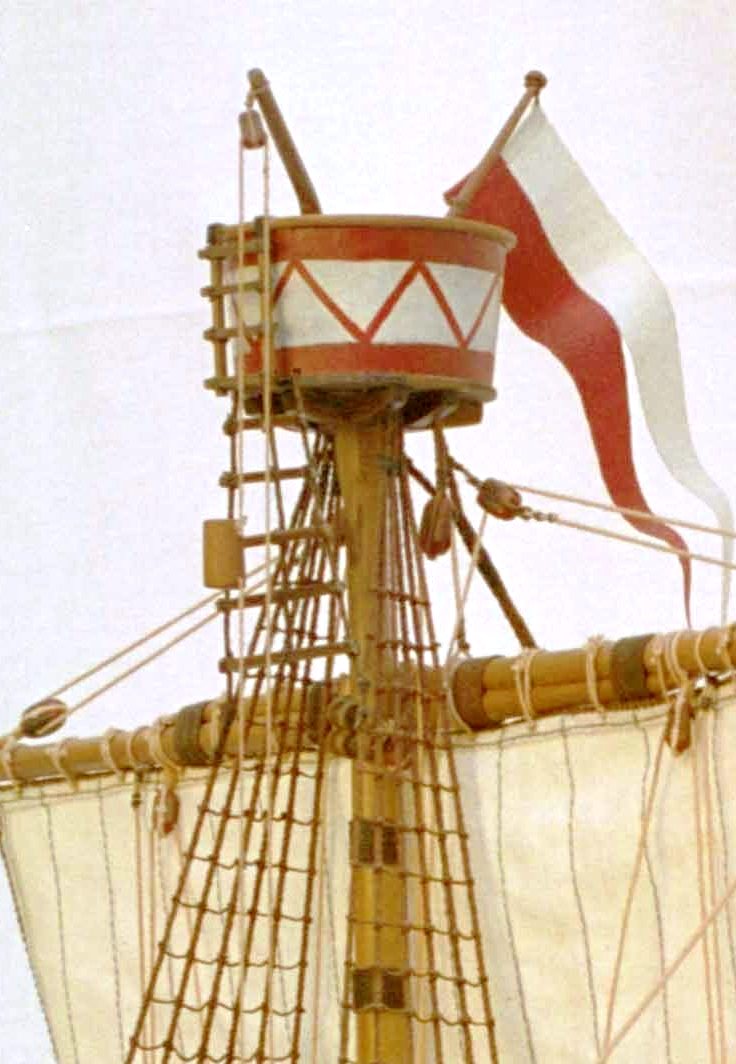
Pulled out the Cocca Anseatica (15th. Century) by Euromodel just to have a look at the drawings. The mast tops intrigued me and I just wanted to share them with you. They had a rope pulley system from the deck and seemed to be a method of sending up weapons and other material to a person occupying the top. Frankly, this is a guess but I hope a logical one. Just so different to the usual tops I have seen.
Any comment would be appreciated.
Pete
- tarbrush, BobH, CaptainSteve and 1 other
-
 4
4
-
What an impressive amount of research. Well done Gunther. However, I have seen all those references before. I must now get back to some actual ship building.
Pete
-
Cabrillo - wish there were more like you. A refreshingly positive attitude goes a long way in encouraging others,..
Pete
-
-
Keith,
Thanks for your great words. The thing I like about the Euromodel RW is that there can never be a prescriptive way of building this ship. That is the beauty of the kit - do your own thing, which is exactly what you are doing. The sad thing is that much time has gone by without adding material to my interpretrive files on the RW. I have been getting many queries for more files on the Friederich Wilhelm, Derfflinger (and a few others) and now the English schooner Lyde is raising its presence. So to all, I have never stopped working on ship-building but just dabbling in a number of different ports.
Pete
-
Likewise Brian, I bought the Keith Julier book (Vol. 1) secondhand and devoured what KeithJ said before opening up the kit box and looking at its contents. It was then that I realized I could improve on what KeithJ did (with no disrespect intended) and it was a great starting point for my build. Now we have VinceP and KeithW (and BrianC is also very active on his great RW creation) creating marvelous works of art which just go way beyond what I had time to do (or could do) . Their works show how far you can go beyond what a kit can readily provide ... and then there are the elite builds of the Royal William such as that by Nigel Brooks. Sorry guys if I missed out somebody but there are so many and these names just come to mind.
Pete
PS Keep these works going shipmates and see how far you can stretch the envelope. Very exciting
-
Keith Julier's book does contain a 'build log' for the Royal William. How many people have actually read his work sentence by sentence - or have they just 'seen' the article ? He was able to cope with the kit as it was and gave minimal criticism and from that point reading his text in detail is worthwhile. Even with the restriction of virtually just using the kit, he still produced - as others have said - a fine model. However, the level of expertise being shown by KeithW is in another totally different realm. KeithW is a fine craftsmen and his work is impressive.
Pete
-
Jan,
I came across many 'one-liner' references to the Dutch use of calculus in the 17C but the text to look at is Dutch shipbuilding before 1800 : ships and guilds / Richard W. Unger. I believe is the one to peruse. If you can find that one - and read it (either written in German or Dutch but not sure), then please pass on to us any useful bits of information.
Pete
-
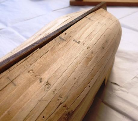
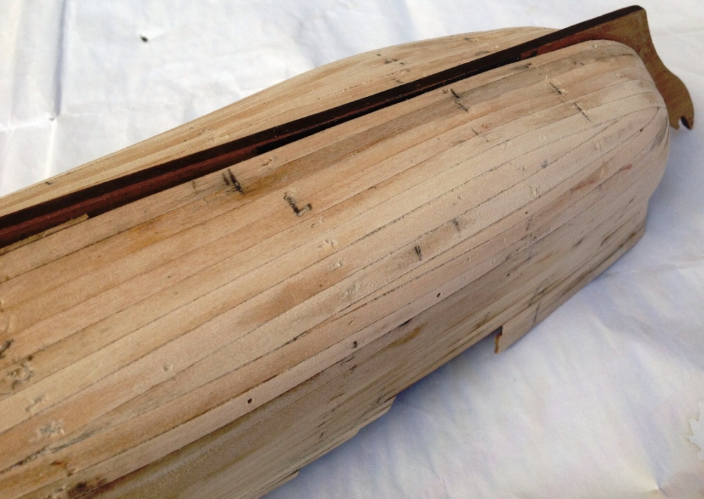
Finishing the First Planking
With the bulwark shape determined, it was time to finish the first planking down to the base of the keel. The only problem here was that the ship needed to be inverted and worked upon without damaging the tall, fragile bulwarks towards the stern. So care had to be taken in designing a support stand.
There is nothing startling to report about the technique used for planking this lower section. The set of photos included here are ‘raw’ and not looking ‘pretty’ - the surface will be ‘filled in’ with wood filler and sanded back to produce a uniform surface ready for the second planking shortly.
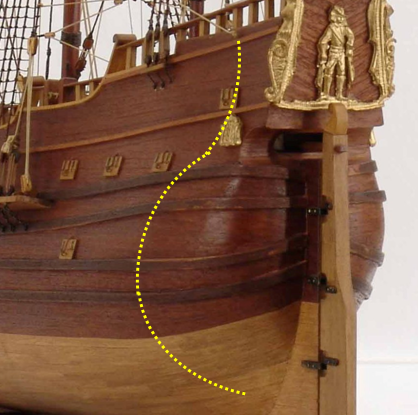
What is worth commenting on though is the profile of the hull section just forward of the Main Mast with the bottom surface being almost flat and quite bulbous, both characteristics together giving a shallow draft for ease of entry into river systems and ports. I have come across such words as ‘pear shaped’ and ‘box like’. These vessels were used commonly in coastal waters and with their minimal armament, they were vulnerable to attack from pirates and other mercenaries.
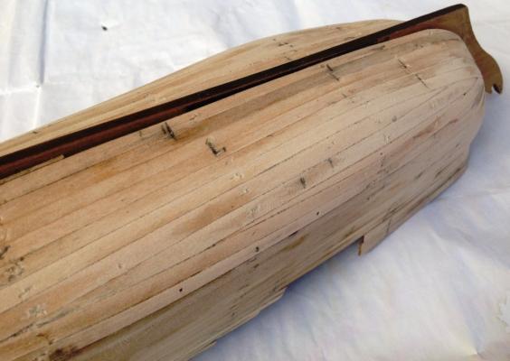
The Dutch are well known to have used mathematics (e.g. integral calculus as early as the 17C) for the development of hull shapes, underwater volumes and hence waterlines for various loads. Now I do not pretend to have the knowledge involved with the designing of hulls but I was just captivated by this particular profile.
-
Thanks for your support Max. The following is just a personal belief ... it is so strange that we bend over backwards to get things as historically correct as we believe they are during the building of a ship ... and then we (myself included) leave the beautiful, beautiful timber with all its glorious texture and colour for all to see. How could it be covered up ? It is at this final stage of building that we dare not add that coat of paint that was indeed used historically. I have just decided to be different with this build. Just a bit of rambling so excuse me as ship-building is all about being individual.
Pete
-
Right on target Brian. It is so easy to become orientated on the usual, popular ships of the English and the Americans. The Dutch were massive ship-builders in the 17C producing ships for a number of other countries, so that deserves some recognition. The challenge is in building a different style of ship.
Pete
-
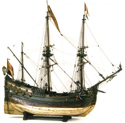
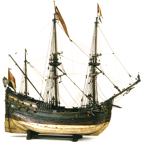
Painting the Derfflinger (or not)
There was a question raised about whether I would be painting the Derfflinger but I was not happy with my immediate response. After doing some research, I have uncovered a photo (seen below) of a fluyt model in the Maritime Museum Prins Hendrik, Rotterdam. The upper hull planking is painted dark green and wales are black but that does not categorically prove that painting should be done [Ab Hoving did not paint the upper hull planking on his model of Tasman’s Zeehaen].
There are also paintings by artists which show completely unpainted topsides on fluyten. Dutch ships, when not painted, were coated with a mix of pine tar, oil and resin which made the timber quite dark, and eventually black.
It comes down to what the builder of a model wishes to do and historically, painting or timber finish both seem to be historically correct. At this stage, then, I plan to paint the upper portion of the hull green/ black and below the water line ‘white’. Between the two painted areas, there will be a relatively narrow band of unpainted timber.
-
Research on the Dutch Vessels - Jacht and Fluyt
I do not wish to hijack my own build log on the Derfflinger but felt it necessary to uncover a few more facts - for myself - and for the forum. The last few days have been filled with a whirlwind of emails to people 'in the know' .I must say this has been an incredibly exciting journey into an avenue of shipbuilding of which I was so ignorant. This is a sad admission since the Dutch nation was a real powerhouse of shipbuilding in the 17 C.
I received the following text from Nick Burningham (nautical archaeologist) who was contracted by the Duyfken Foundation in Western Australia to design a full-scale replica of the Duyfken. I gratefully acknowledge his authoritative comments ....
“ … Dutch jachts and fluyts were similar in the sense that all sea-going three-masted ships of the same era and same place of building were similar. Terms such as jacht and fluyt were not formally defined in the way that later terms such as schooner and brig were.
However, there are major distinctions between the two
- a jacht was a fast, armed vessel with a square tuck stern, but
- a fluyt was a capacious cargo vessel with a round stern (not a round tuck stern).
Fluyten were sometimes armed, but they were not developed as armed vessels.
[Karl Marquardt did try to argue that jachts were round-sterned vessels [Marquardt, K.H., 2007. The Duyfken enigma: some alternate design possibilities. The Great Circle] but Nick suggested that there was insufficient evidence to support his comments]
In my article I make the point that the jacht is primarily a term indicating function and performance whereas fluyt primarily defines hull-form. Although a jacht usually had a square stern, a fast and armed, round stern ship could be regarded as a jacht, but it would be called a flieboot or vlieboot in the early 17th century….”
My comments ...
For those interested, Nick Burningham’s excellent article is worth reading and is called : The Flute; histories and mysteries and myths. MHA Journal Vol. 13 (3)
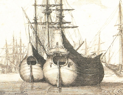
The fluyt had a very distinctive shape and purpose to have a large loading capacity whilst minimising the number of crew members necessary to sail them. The result was a much rounder and bulkier hull and steeper bulwarks towards the stern. In other words, these ships often displayed a long tumblehome design. The stern, like the bow, was quite rounded.

The sides of the ship inclined towards the inside at their top, creating a much smaller deck. Ships passing through the Danish Sound Strait into the Baltic Sea had to pay taxes (‘Sound Dues’) based on their deck surface area. Reducing the deck area resulted in a significant decrease of these taxes while actually increasing the carrying capacity of the vessel.
The unique design of the fluyt did cause some problems - if used in the tropics, the clinker design of the bulwarks and bulkheads accumulated moisture leading to wood rot and the rounded bow exposed to the harsh sun caused considerable cracking of the timbers. They were better suited to the European climate where they were so commonly used.
-
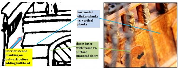
Main Deck Bulkhead (Aft)
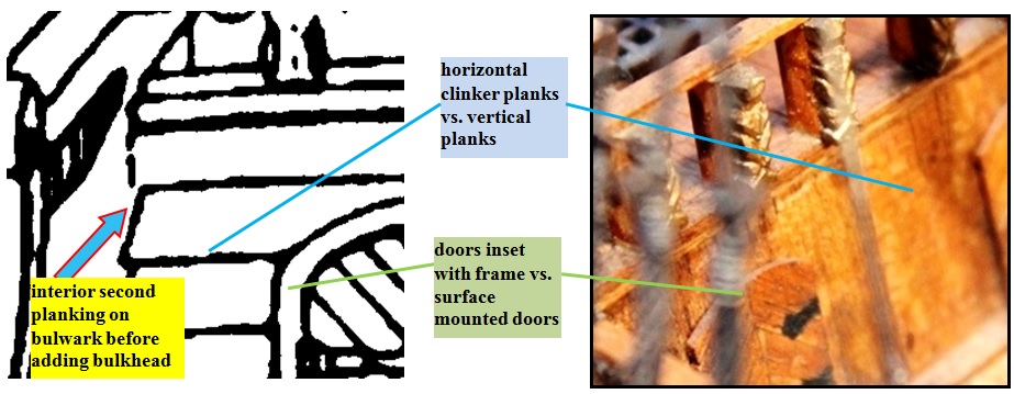
There was both an aft and a forward bulkhead built on the Main Deck. The interesting thing here is that it was usual practice in Dutch ship-building during the seventeeth century to apply horizontal clinker cladding over the bulkhead surfaces. This style had no consequences in European waters but in the moist tropics, it easily led to wood rot. So whether the builder chooses to do this or be conventional with vertical strips is their choice. I went with the former style.
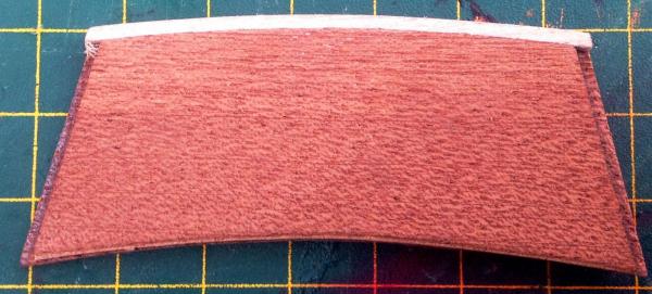
The drawings had to be carefully measured to obtain the correct slope on the bulkhead because that influenced the length of the over-lying planks of the Quarter Deck. I was a little concerned that the supplied plywood piece for this bulkhead was not quite wide enough (but that was being super-fussy) so another piece of plywood was glued onto the forward side of that piece as well as a piece of first planking being glued on the top edge. This doubling up of the bulkhead actually worked to my advantage when cutting out for the doors (see further down). The extra height allowed for the tapering of the top & bottom edges due to the sloping bulkhead.
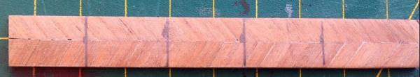
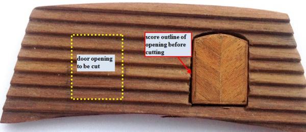
One piece of thin plywood approx. 12 x 84 mm. was laminated with 0.5 mm. scrap planking strips, cut into five over-sized doors and then shaped to size. Laminating one long strip made the process so much easier. The doors without edging were 11 x 15 mm. - a little shorter than shown in the drawings but I needed to leave room underneath since the bottom edge of the doorway would have been above the deck surface. To the door edges were added strips made from scrap 0.5 x 3 mm.
At this stage, clinker planking had been started to establish a base line for the doors. Rather than fuss around with short pieces of planking around the door openings, I decided on full planking and then cutting out the doors. Having said that, it seems not uncommon for builders to just add the doors over the surface of the bulkhead !
Although the original instructions suggested using 1 x 3 mm. timber for the bulkhead planking, I would have been much better off using the 1 x 4 mm. second planking timber - both for appearance and ease of cutting through. Hindsight is a wonderful thing !!!!
A doorway recess was cut into the top layer of plywood.
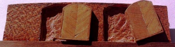
With this space underneath, the cutting out of the actual doorway through the clinker planking proved to be a very simple exercise. When the doors were finally fixed in position, these spaces were re-filled with some short pieces of first planking timber. Certainly that was extra work but it seemed worthwhile.


Euromodel Como Kit Discussion
in Wood ship model kits
Posted
Enough of the words JP ... let's see this French frigate abuilding !!! Its unfair to suggest and not show.