HOLIDAY DONATION DRIVE - SUPPORT MSW - DO YOUR PART TO KEEP THIS GREAT FORUM GOING! (89 donations so far out of 49,000 members - C'mon guys!)
×


rlb
-
Posts
655 -
Joined
-
Last visited
Content Type
Profiles
Forums
Gallery
Events
Everything posted by rlb
-
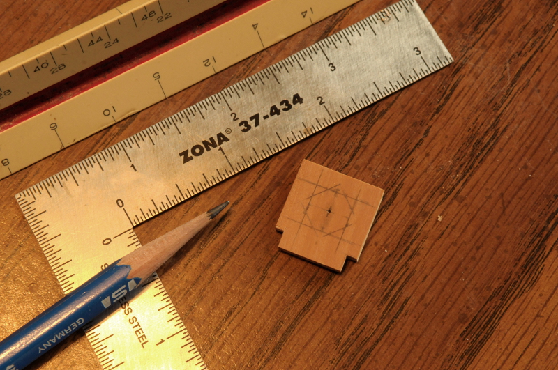
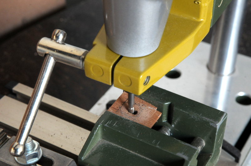
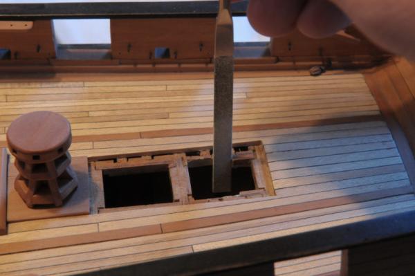
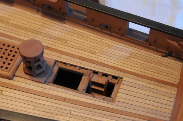
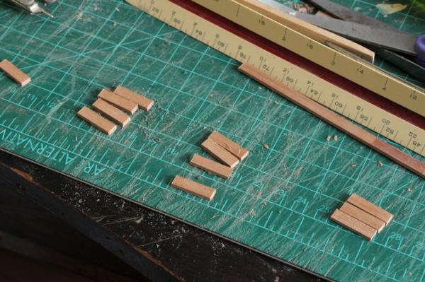
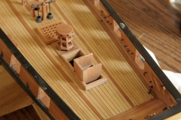
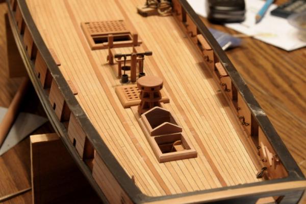
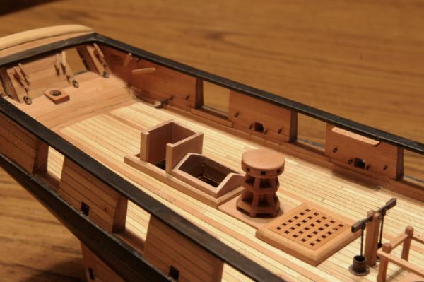
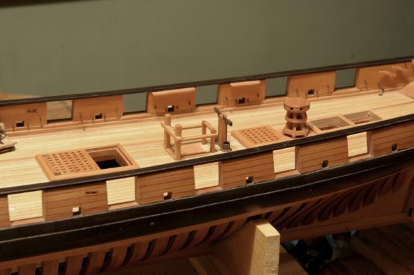
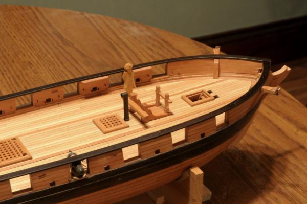
 Finishing up the pin rails: Here's how I revised them, so they continue around the aft post at the same height. Moving on to the mast partners, I drew an octagon with at the correct size of my masts-- And milled the center out, a little smaller than the drawn octagon. Notice the wood is at an angle to account for the mast rake-- I filed the corners of the octagon a little better, then fit the partners on the deck. The octagons will need to be enlarged to fit the actual masts when they are made-- The aft hatch arrangement: I finally settled on what to do with these last hatches. It's changed from my initial idea, and I needed to do some surgery to the framing to accommodate a companionway in the second opening-- I glued in a ladder I had made a long time ago-- Some pieces cut for the companionway sides-- The pieces that make up the sides were glued together, and when set they were sanded flush, trimmed to the right size, and glued into a "box"-- Just aft of the companionway, on what's left of the coaming, I'll build a binnacle. The opening forward of the companionway will be a skylight. Here is the frame test fit-- And then both test fit together-- Ron
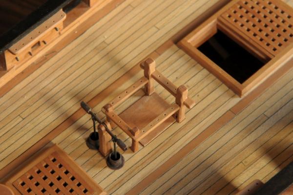


-
Hi Russ, I know doweling those pin rails is a good idea, but it's very small and three pieces coming together at one place. I'm afraid to drill into the wood in two directions at that aft corner where the two pin rails come together. I put some generous fillets of glue underneath, where it won't be visible. Perhaps before I glue rail sub-assembly onto the topsheet bits (this joint does have epoxied pins) I will drill and put some treenail dowels into those corners. Ron
-
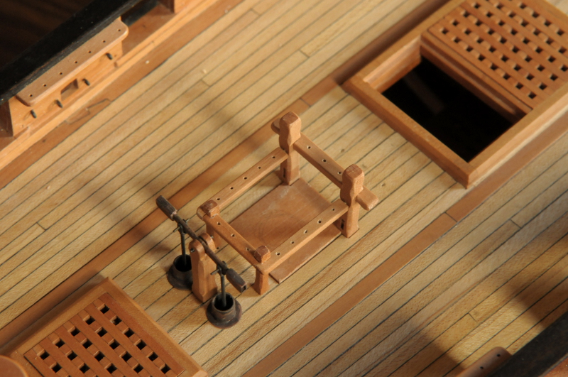
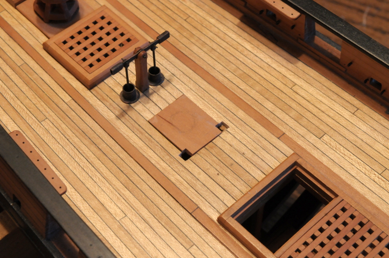
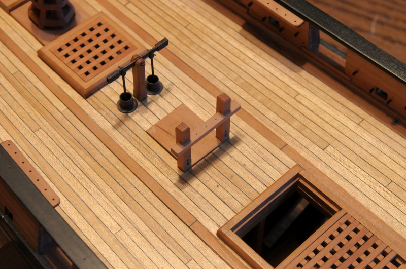
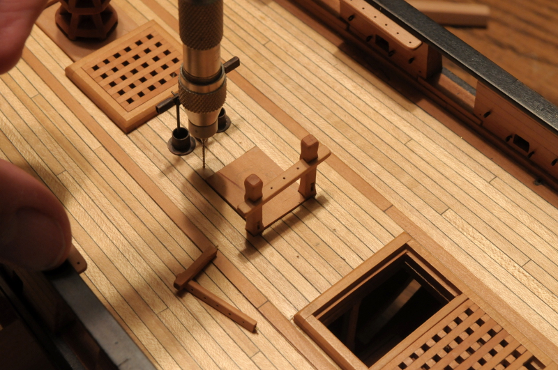
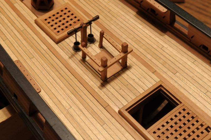
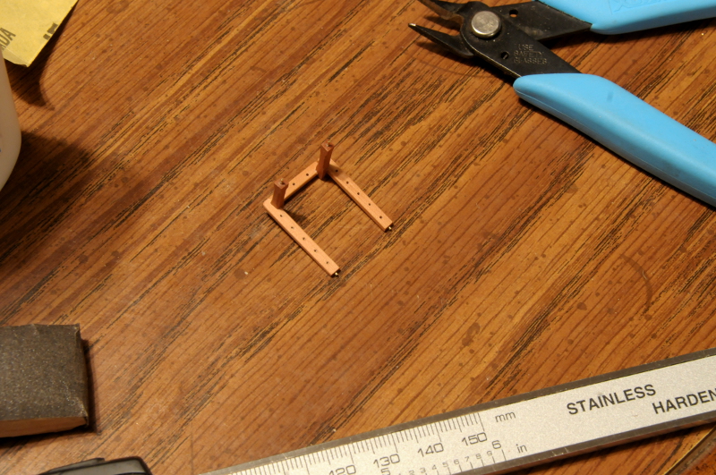
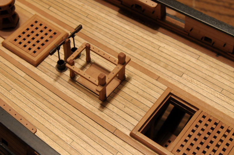
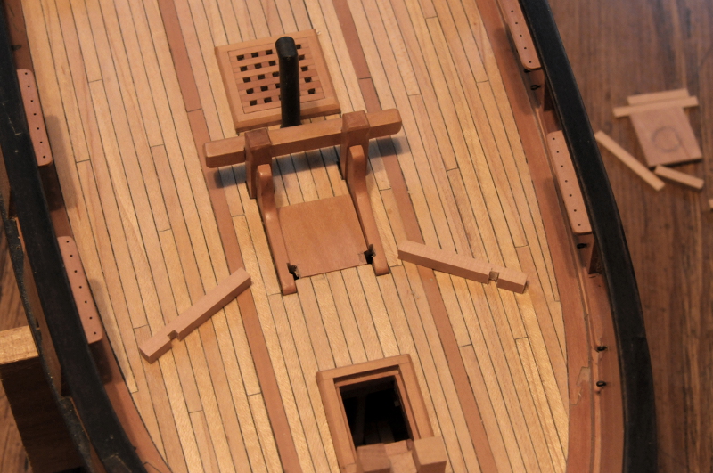
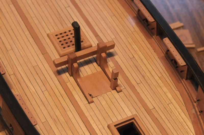
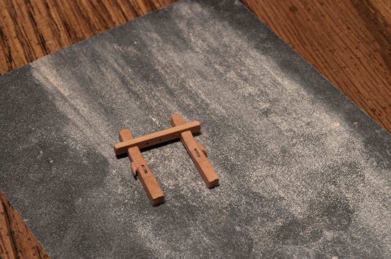
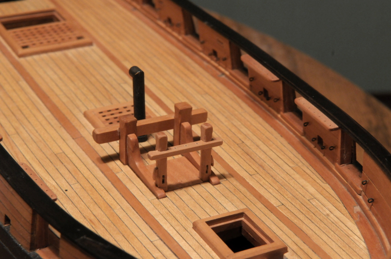
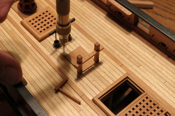
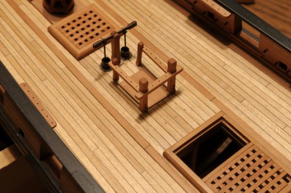
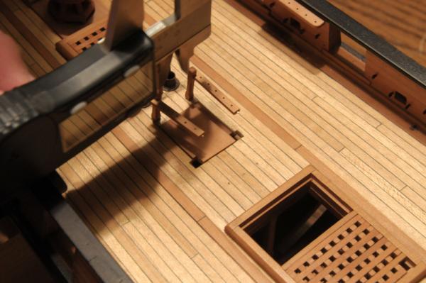
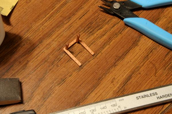
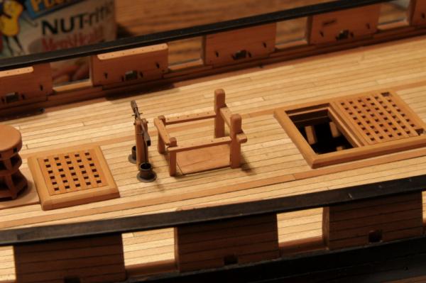
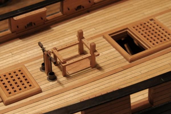
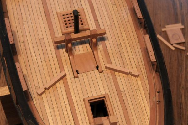
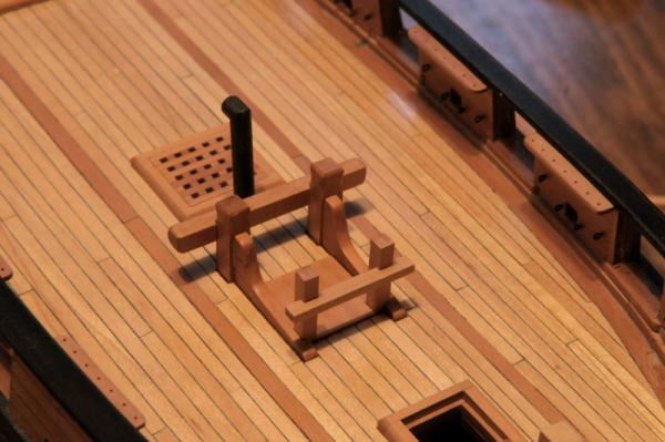
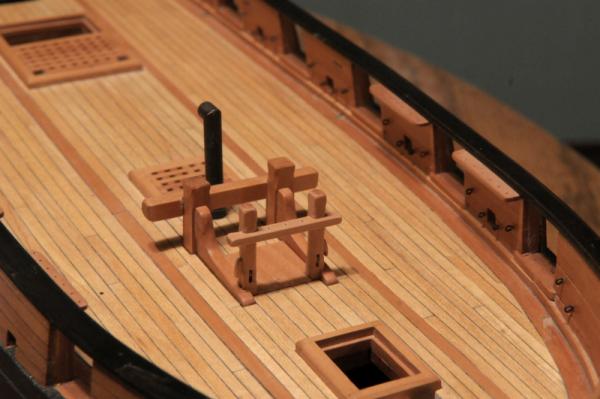
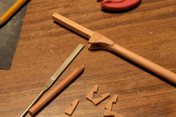
Continuing on with the topmast sheet bitts-- The main pieces are similar to the fore mast sheet bitts, but for the main mast there are some extra pin rails and posts. First, the partners, and the decking are notched for the bitt posts-- These are dry fit-- The main posts, aft posts, and pin rails are shaped and partially glued. Pins are epoxied into the ends of the side rail sub-assemblies for strength, and to make gluing easier-- Holes are marked and drilled in the deck for the aft posts-- More dry fitting-- Measuring for fitting the aft pin rail-- The aft rail is cut and glued to the side rail sub-assemblies-- More dry fitting-- I'm not happy with the aft pin rail. It looks a little flimsy. I remove it adjust the notches, and re-glue it-- This is better, but I'm not sure it's good yet. I was going for something similar in basic concept to the mast rails on the Brig Niagara replica, where the side and aft rails are at different heights, but I'm not sure I like this. I think I will remove the aft rail, trim it, and the side rails, and attach it so that all three are at the same height. The sheet bitt posts also need the side cleats made and attached (as on the fore mast sheet bitts), but those and the rail adjustments will have to wait for tomorrow. Ron


-
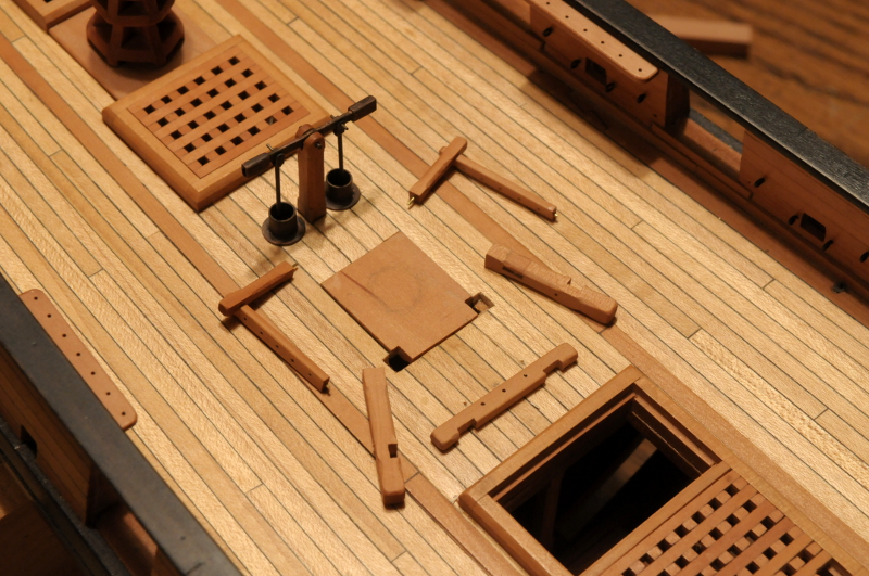
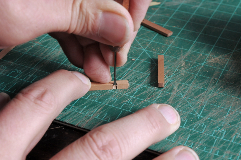
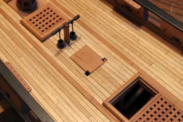
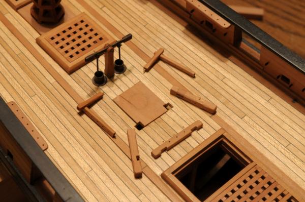
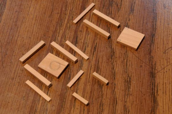
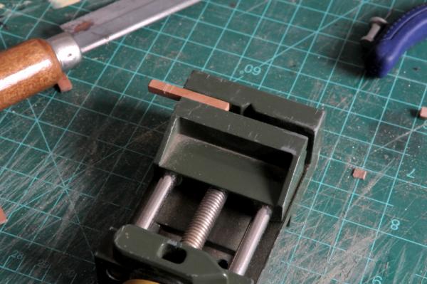
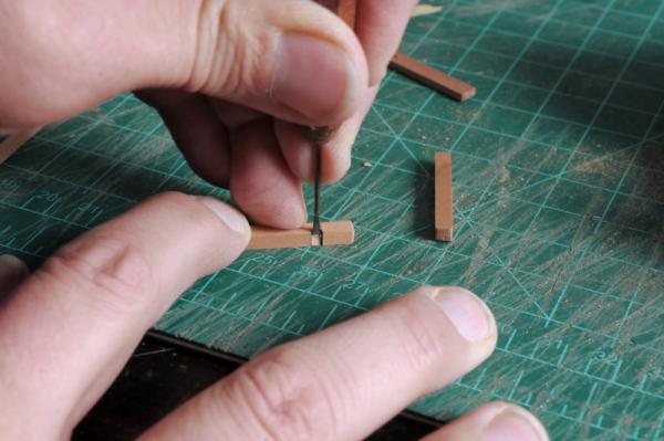
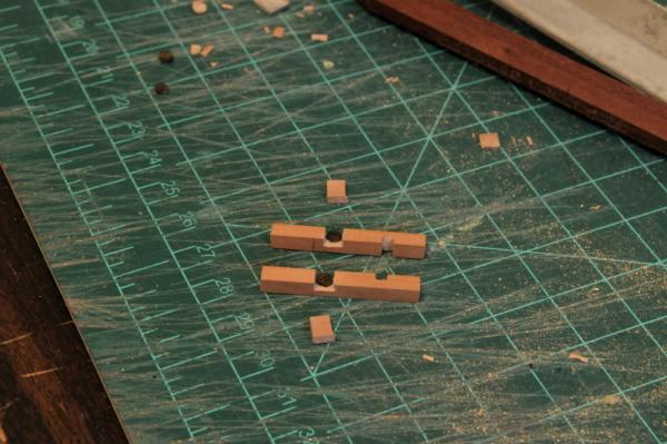
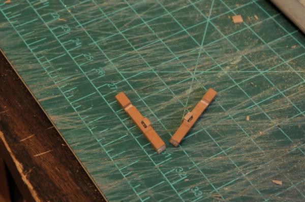
Today's project was the topmast sheet bitts. Here are the basic pieces for both the fore mast (above) and the main mast (below). Some square posts, pin rails, and the as yet unfinished mast partners I began working on the fore mast bitts. These are the simpler of the two, with only one pin rail, athwart the posts. First I cut the notch for the pin rail-- And chiseled it out-- Here are the two posts laid on the deck. The knees for the riding bitts need to be notched to receive the posts, and the mast partner piece will also be notched out in the corners-- One post is dry fit-- Here are the two posts and the pin rail dry fit--still a lot of work to do-- A sheave needs to be put into each post. Here are the posts notched for the sheaves, which are stained pieces cut from a dowel-- After the sheaves are glued in, a filler piece is glued, these will be sanded down flush-- After sanding down the filler pieces, adding a cleat to each side, and some further chamfering and shaping, here are the fore topmast sheet bitts-- And dry fit on the model-- Ron


-
This is the first time I have seen washers, threads, and nuts on model eyebolts, but at your skill level I am not surprised, only delighted! Ron
-
Thanks, all, for your comments and "likes:. I am into quiet-mode research during the week (as opposed to beast-mode modeling on the weekend). Up to now, I've spent untold hours staring at belaying plans and rigging details, without it really sinking in. I have to make a detailed belaying plan for Oneida before I finish my bulwark pinrails, and mast pinrails/fiferails. It will be largely based on Chuck Passaro's Syren drawings, with some additional reference to Petersson's and Lees' books to fill in some info, for my Oneida's variation. I'm really walking through each piece of rigging (standing and running) to figure out where it all goes, and whether I want/need (at least on some of the running rigging) to include it. It's a big effort. In addition to that, I'm researching the ship's boats. Chapelle lists a 32 foot launch and 20 foot boat, with a 16 foot stern boat added in 1813. I've decided that I don't really want to model the stern boat, though I am using the 1813 gun armament with the two six pounder long guns in the bow--possible inconsistency there. A thirty-two foot launch (which seems huge compared to the standards I've been looking at) would hardly even fit between the masts; if Oneida really had one that size it must have been towed behind--so I don't need to model that. What I will make is a 20 foot cutter (or gig?) to be stowed on the deck between the masts. Ron
-
Your planking looks great, Adriaan. Nice work on the curved one at the bow--much better than small bits of vertical planks! Ron
-
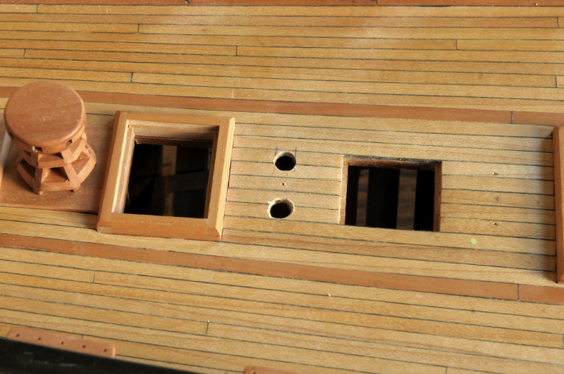
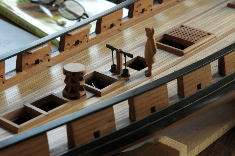
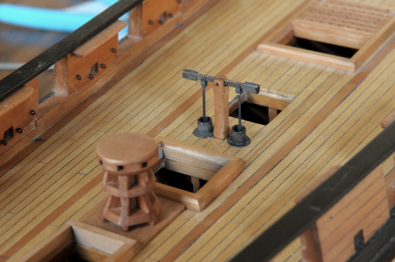
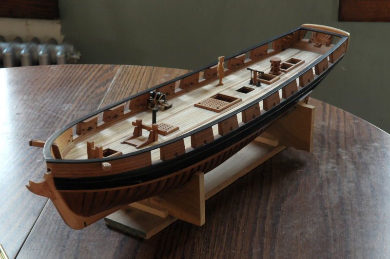
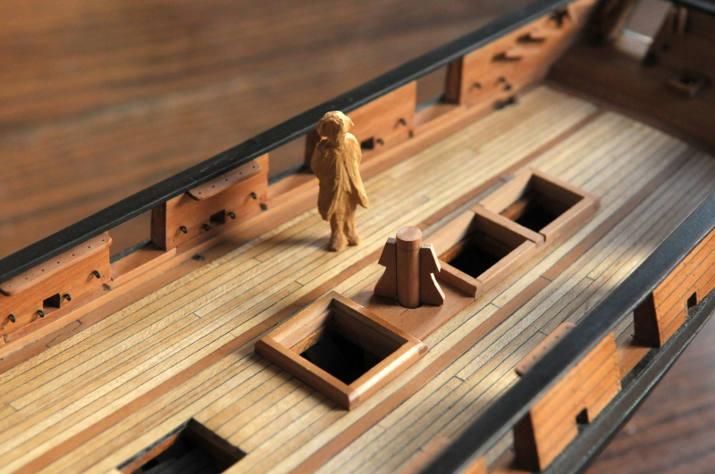
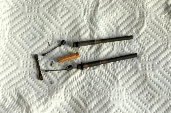
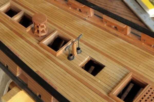
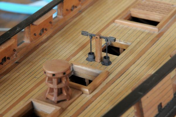
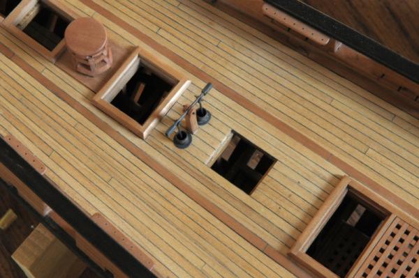
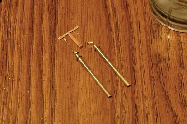
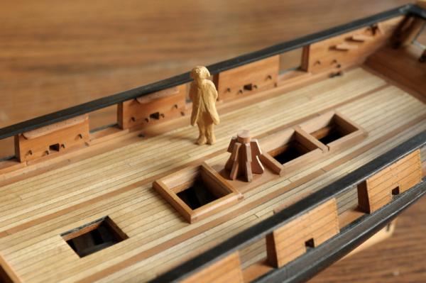
Continuing with the pumps-- Here are the pieces blackened-- I didn't have particularly good luck on this batch, though I followed my usual procedure: wash the pieces in soap, and then rinse well, use about an 1:8 solution of Blacken-it and water, wait a while! I did the rocker arm and one of the pump tubes twice, but still some "light" areas. Two holes were bored in the deck (and lower deck on the starboard side)-- To the right you can see a mark, and two pin starter holes where I nearly drilled!! That would have been a pain to fix. I think I can take care of the small holes by filling them with sawdust paste so they don't show. Here are the pieces dry fit-- And here they are glued-- The only difference in appearance between the dry fit photos and these, is the small wire pins to hold the plunger rods to the rocker arm. I still need to trim those, and then I will glue the rocker arm in this horizontal position. The valve stirrups are too fragile (they've been filed dangerously thin to make sure the valves slide in the tube) to take a chance on them breaking if the pump is "worked". I will probably make small washers for the main pin in the rocker arm pivot and support stanchion--it looks like it needs them. I won't do that on the small pins though, they'll just need a spot of glue so they don't fall out. One more overall photo-- Ron


-
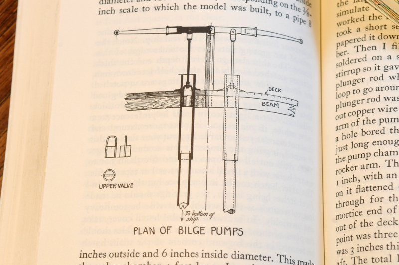
Thanks, everyone for all the "likes" and always for comments, as well. Sam, I think there would be a leather "flap" for the upper valve, and as well for the lower valve, which isn't indicated at all. This pump (and the one Davis illustrated in his book) isn't meant to show all the pieces necessary for it's operation. Only the parts that can potentially be seen are drawn, and modeled. The stirrup of the upper valve, where it is held by the plunger rod, is barely visible, but nothing else within the tube is. Ron
-
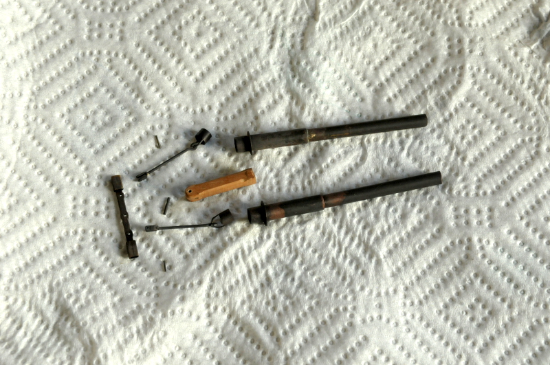
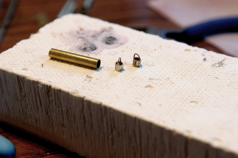
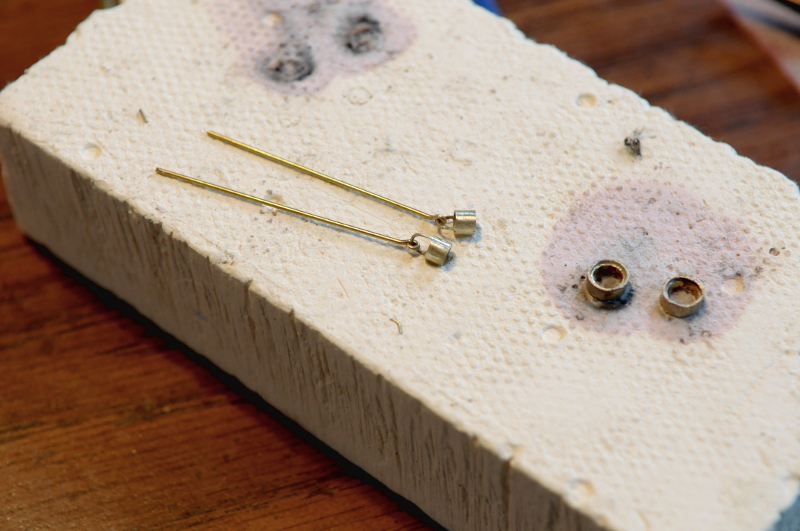
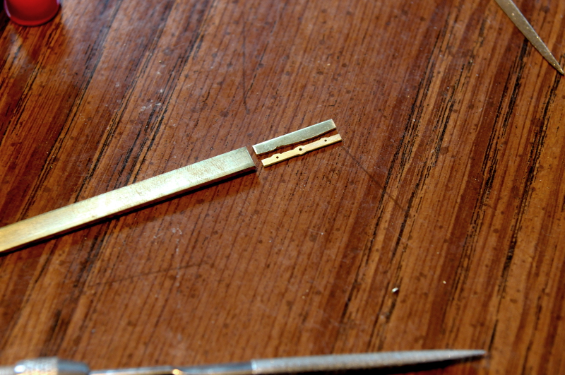
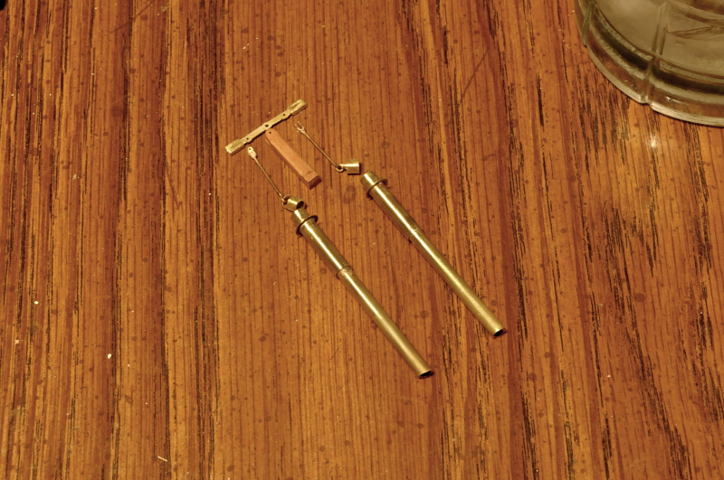
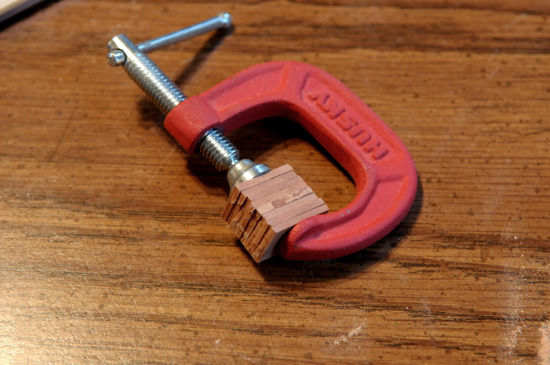
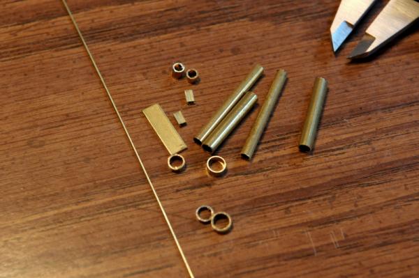
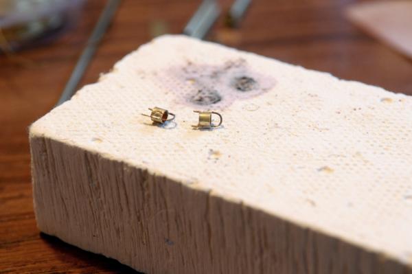
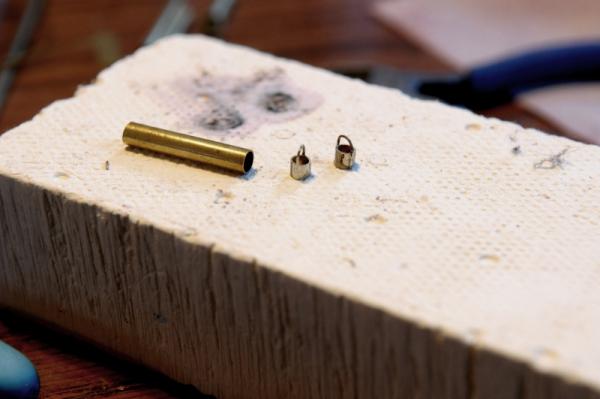
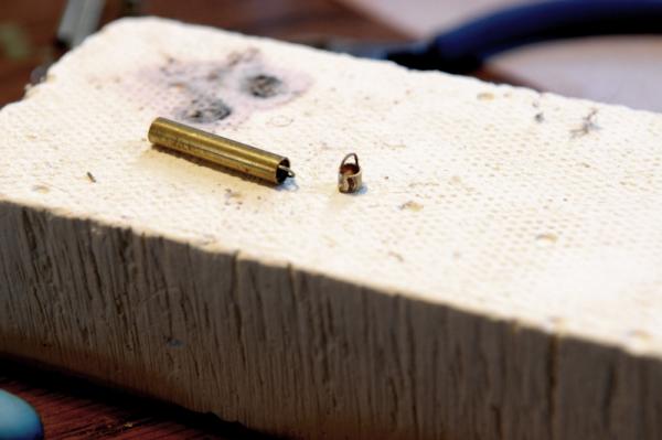
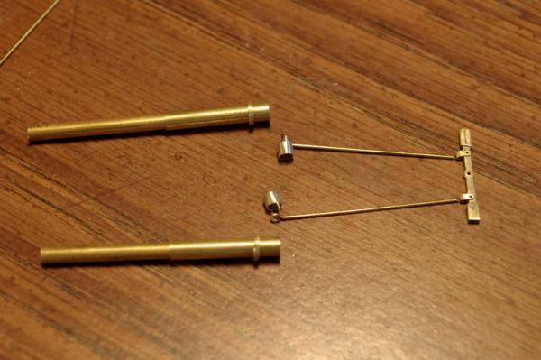
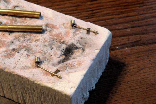
Today, I did a lot of brass work, and soldering, in working on the pumps. My basis-of-design is from Charles G. Davis in "The Built-up-Ship Model"-- Here are most of the pieces needed, various diameters of brass tubing, rod, and bar stock-- First I soldered some bent rod to scores cut in the barrel of the upper valve pieces-- These were then filed back to the diameter of the tubing-- So that the valve would slide into the pump chamber-- Loops were made at the end of lengths of brass rod, for the plunger pieces-- Out of bar stock, the rocker arm was rough cut, and filed-- Here are the pieces, just about all assembled-- The "sockets" on the ends of the rocker arm are some square tube that I hammered down a little to make it rectangular, and then soldered to the rocker arm. After determining the correct length of the plunger rods, I soldered u-shaped attachments. I had to do this three times before I got a solder joint that held-- I also had to redo the flange pieces for the tubes. I ended up hammering down a ring cut from a larger size tube, and then, since it wasn't perfectly round after the hammering, I filed it inside and out so it would fit the tube and be round--it looks much better than what I had before-- Next will be blackening and assembling the pumps. Ron


-
Thanks, Ben, Sam, Pygothian, glad to have you aboard! Dan, thanks for your photos, they are useful! Lou, sorry to hear you reached a standstill with your Oneida. There is, indeed, a lot of sanding and fairing necessary. If you resurrect the build (which would be great!) I do recommend a jig for the bow and stern framing. You need something that helps you locate the outline (not a nautical term, but I can't think of what the proper language would be) of the frames, not just making sure they are vertically plumb. Either a gantry and framing board, or a fixed, "elevated" jig should work. I had problems with both the bow and the stern because I didn't use one of these methods. The bow and stern half and cant frames needed even more sanding than the full frames, so just be prepared for the effort! It is worth it. Ron
-
Hi Dan, That is a great model, and I would love to see you finish it! At the very least please put your photos (and more if you have them) in the gallery section of MSW! There are others here who are building Oneida, thought they don't have logs going--I'm sure they would love seeing more photos of your model. Can't believe it's only half the size of mine--you've got just as much detail. I like what you did with the aft deck area. Regards, Ron
-
Thanks for looking in, B.E. When I get further into the masting and rigging, your Pegasus log is going to be of immense help! Thanks, Keith. I think you're right that attitude is the most important part. Almost anything on the model can be made with hand tools, just look at those beautiful period model ships for proof. That said, if I had more money and the space, I would probably have some of those "fancy toys". Congrats on your ship building anniversary, glad you're still going strong. Ron
-
Announcing the Model Ship World Ship Kit Database Project
rlb replied to SkerryAmp's topic in Wood ship model kits
There is also The Lumberyard, though they are somewhere between kits and timbering sets. There's a link to their site at the same area of the forum home page, a few banners up from your Database link--you can check out their kit offerings there. Ron -
Thanks, Martin. Yes, I try to keep from overloading the scrap wood bin, but you know how it is... Elmer, the blackening "tea" is a recipe I came across some time ago. You can learn more about it here: http://www.popularwoodworking.com/techniques/ebonizing_wood I think it gives a really rich deep black to wood that's better than paint, plus it's fun to do! There are other "easier" dyes available also. There's a forum topic going on right now about "ebonizing wood", in fact. Michael, the mast problem is that it is tapered too much at the lower portion of the hounds (at that point mine measures .285 inch, it should be somewhere around .31 inch--and that's enough to see) This was the result of two errors: 1) I by accident used the taper ratios given in James Lees' book for pre 1800 ships (mine is 1809) and compounding this (2) I took my measurement at the base of the hounds, instead of at the top of them, where I now believe it should be measured. As I was doing the tapering, it looked to my eye like too much, and when I went back to the references I have at hand (James Lees' Masting and Rigging, and Charles G. Davis', The Built-up Ship Model), I discovered my errors. I continued on, attaching the bibs at the hounds, and thought about using the mast anyway (especially considering all the work--cutting it with the jewelers saw, all the hand sanding), but I just can't live with it. Ron
-
Michael, "The thanks have to go to Mr Prince My old junior school teacher who knew how to teach woodwork and coax the best out of the boys. Woodwork was my favourite class, next to drawing and metalwork." Why am I not surprised! You have a truly delightful model going, and the building surprises never stop! Ron
-
I remember Karl's tragedy. For whatever method you devise to prevent this, is there some way you could do a test first? Ron
-
Thanks, Elmer. Don't hold your breath on the shipping time. It took a few months to get mine--yours may be faster, but maybe not. I think Dave at the lumberyard has to send the wood to a third party to get it laser cut, and I'm guessing he doesn't keep a stockpile of kits, ready to go. It's probably not a high volume item, and each one may be prepared as the order comes in, especially if you want the more expensive woods. Ron
-
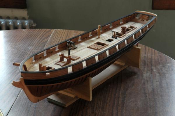
Thanks, guys. I'm pleased with the capstan. I'll be continuing on with the deck furniture next. Ron
-
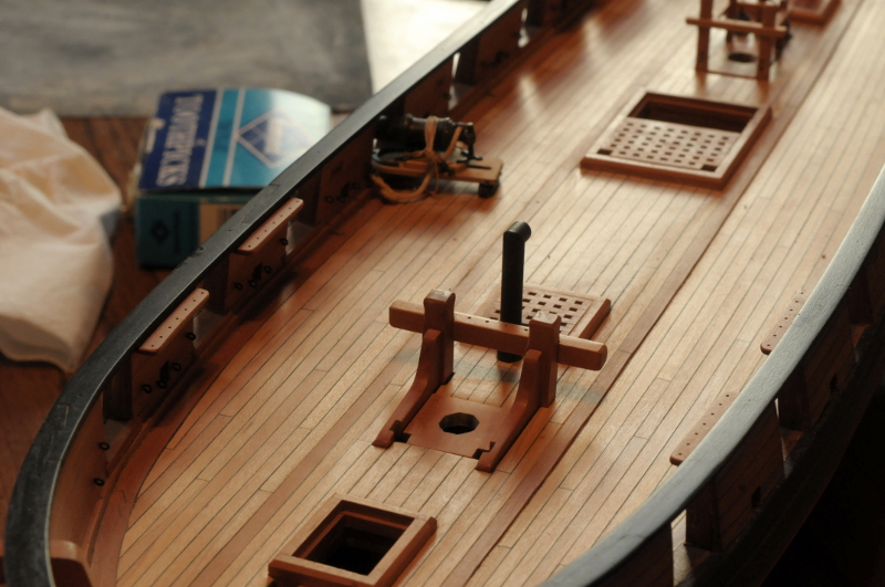
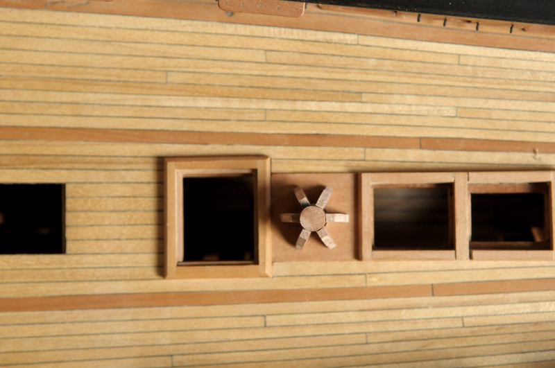
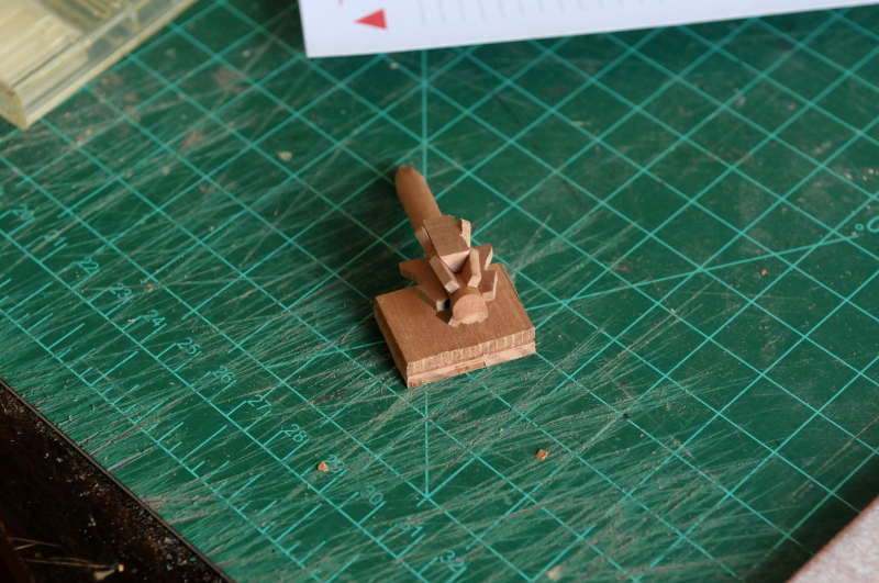
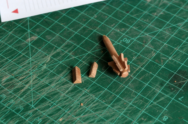
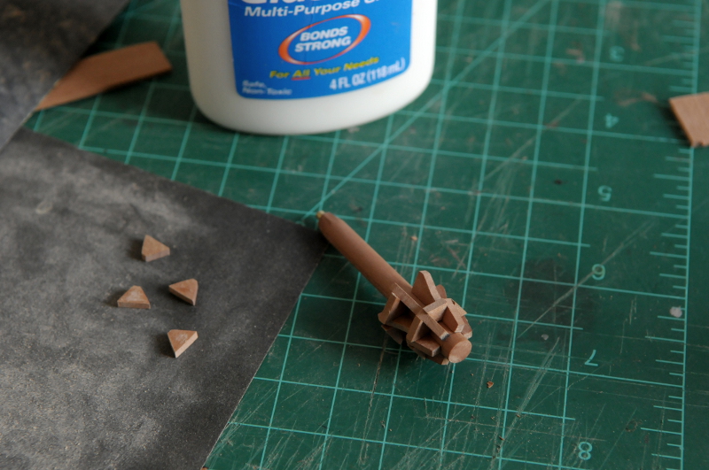
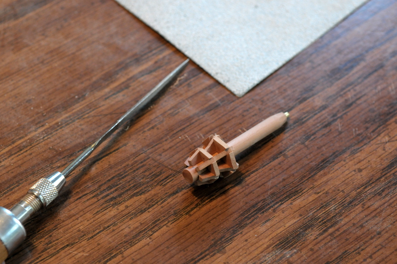
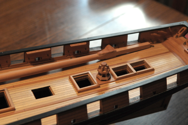
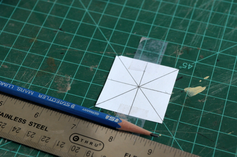
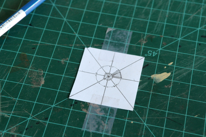
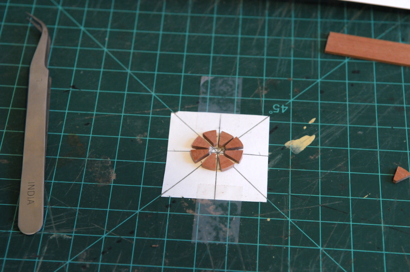
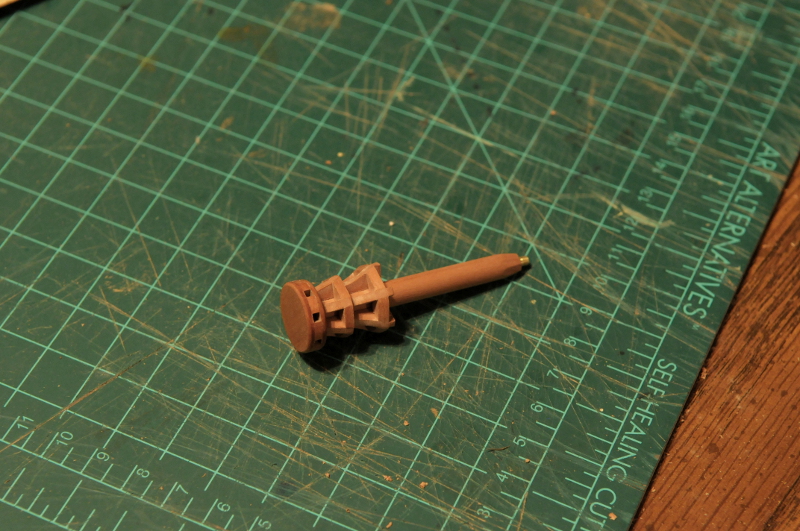
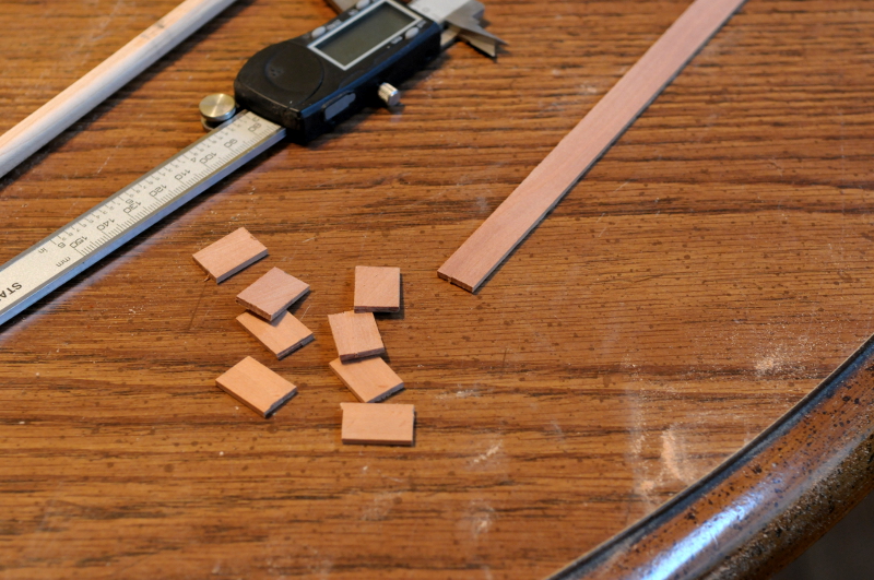
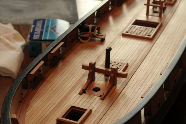
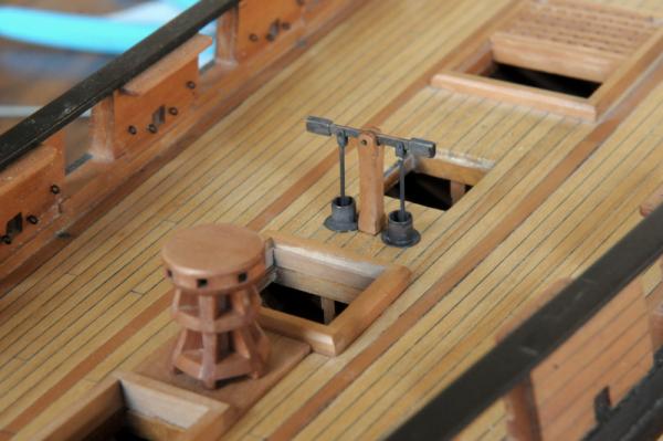
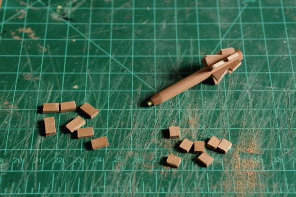
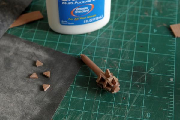
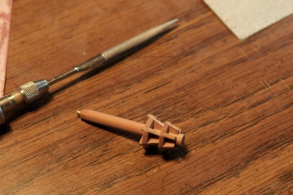
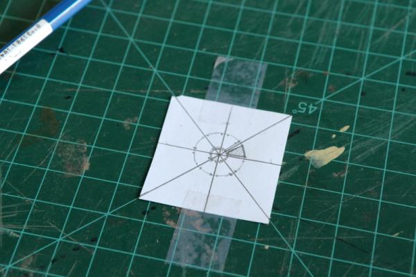
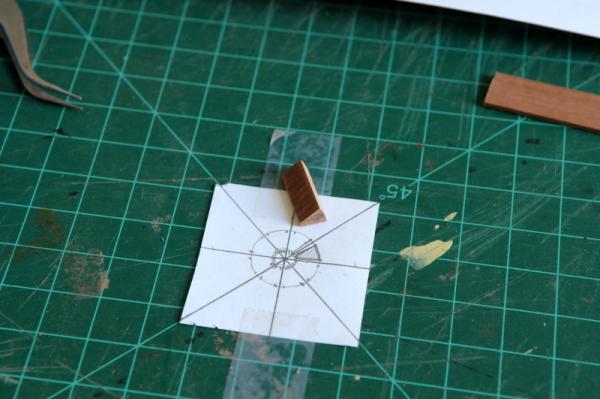
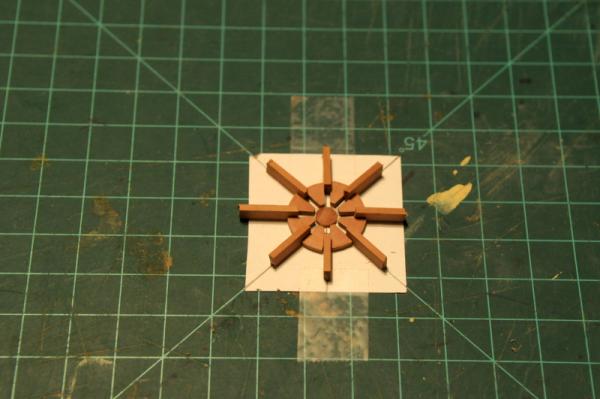
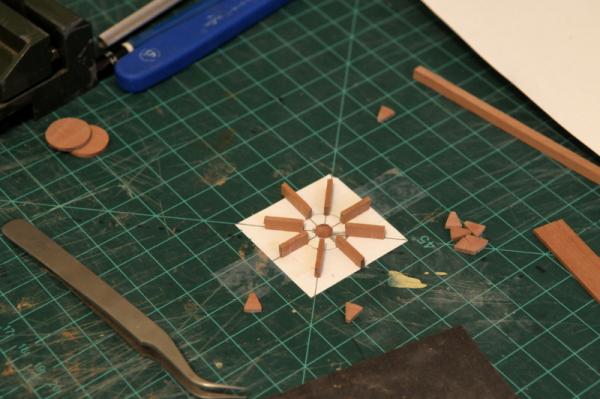
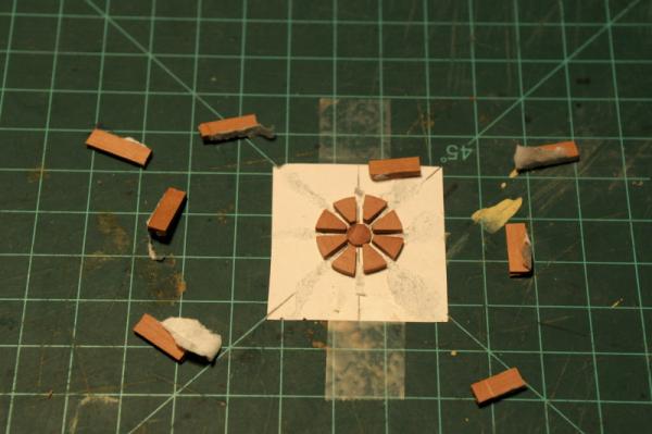
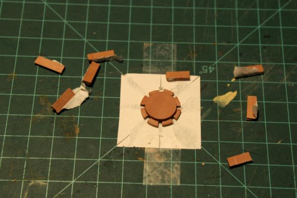
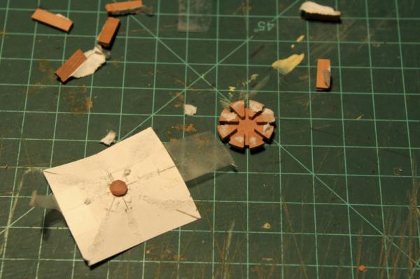
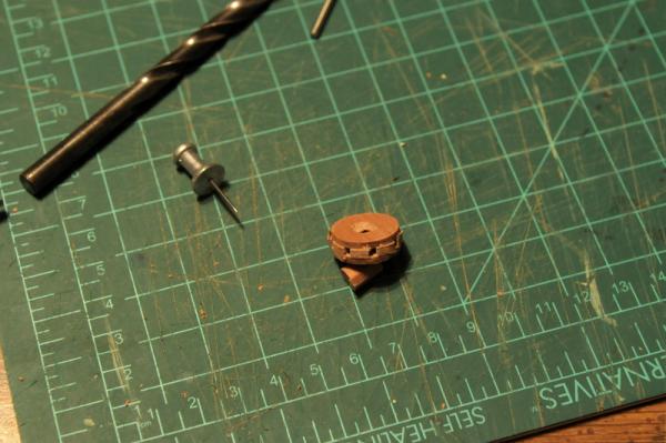
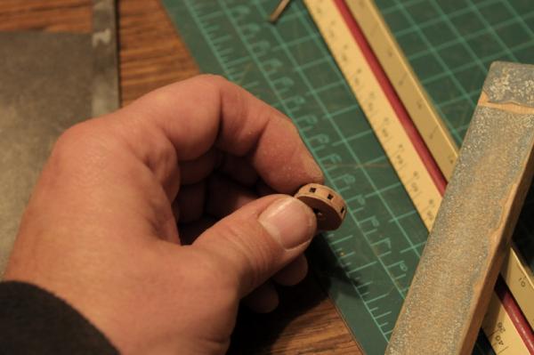
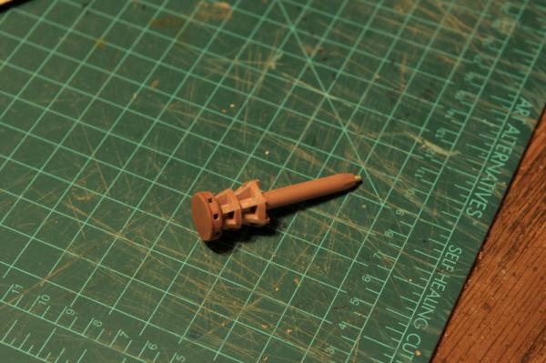
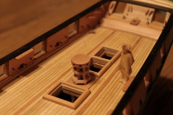
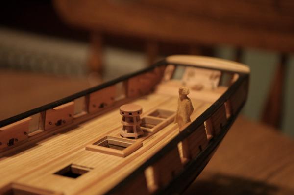
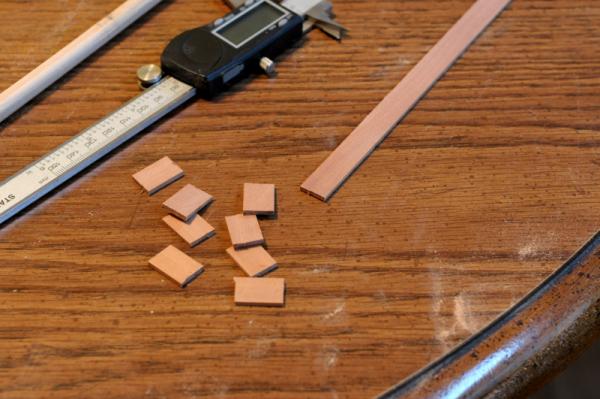
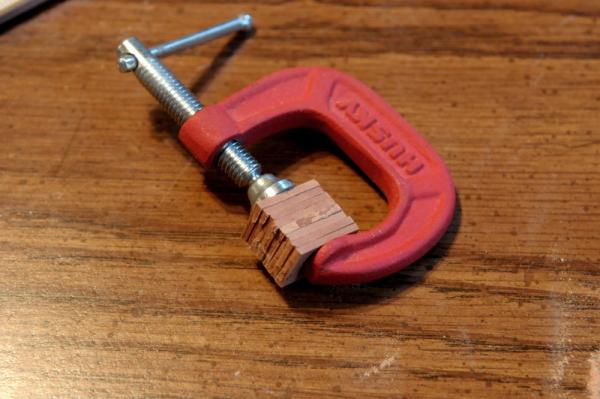
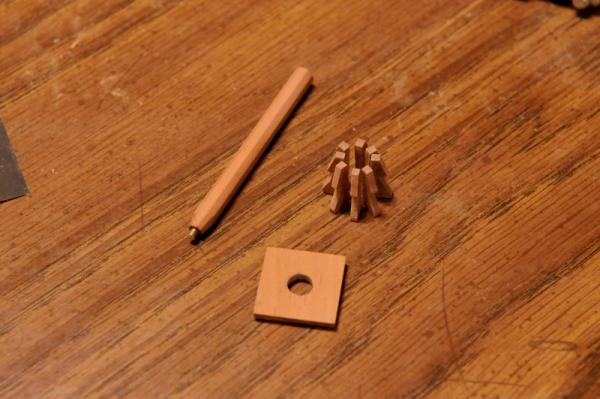
Continuing with the capstan- As I looked again at various capstans to glean some details I was still fuzzy on, there seemed to be more space between the whelps than I was coming up with, and it dawned on me that what I wanted to make had only six whelps instead of eight. The eight capstan bars that I saw on models, I mistakenly took to correspond to eight whelps as well. Not so in this case. Upon learning this, my octagonal post was not going to do me any good and I sanded it round. I glued two opposing whelps to it, and test fit this on the deck-- The height seemed about right, and I glued the remaining whelps on by eye, trying to make sure they were perpendicular to the shaft, equally spaced, and all at the same height-- Next I made the chocks. Two sets would be needed, and I used the same technique as for the whelps: cut out blanks, glue them into a block, and sand them to the desired shape-- Here I have sanded one chock block and am test fitting it-- Here are my two chock blocks-- These were separated in hot water, and glued into place-- They need to be filed down to the same profile as the whelps-- I then tried this out on the deck again, and pondered exactly how to make the capstan head-- Incidentally, you see the mast I had made, on the deck. It will be a do-over. I found some better information on mast tapering (from my old friend Charles G. Davis, no surprise), learned I had made a mistake ( a couple, actually). Oh, well. This one will do fine for helping me make the mast partners and locate the right chain plate angles. I started the capstan head by drawing the location of the eight capstan bars on a piece of paper-- Then I did some measuring, marking and sketched out the shape of a "capstan bar chock" that would be sandwiched between two discs, and create the square capstan bar hole-- Once again, the chock block technique was employed to create eight uniform chocks-- These were separated and tested out on the drawing-- I cut some "stand in" capstan bars out of stock exactly the same thickness as the chocks, so I would end up with square holes. These were glued onto the paper, centered on the lines I had drawn-- Then I glued the spacer chocks onto the paper, between the stand-in capstan bars-- It didn't matter that the spacer chocks extended unevenly beyond the outline of the capstan head, the excess would be sanded away. The bars were removed-- Then the top disc of the head was glued to the spacers-- When the glue set, the assembly was removed from the paper-- The bottom disc was glued on, and extending bits of chock were sanded away-- Here it is partway through the sanding-- When it was smooth and as round as I could make it (it rolled across the table pretty well), I glued it to the whelp assembly-- And tried it out on the deck-- I will make the pawl mechanism and attach that to the deck, then it's done. Ron


-
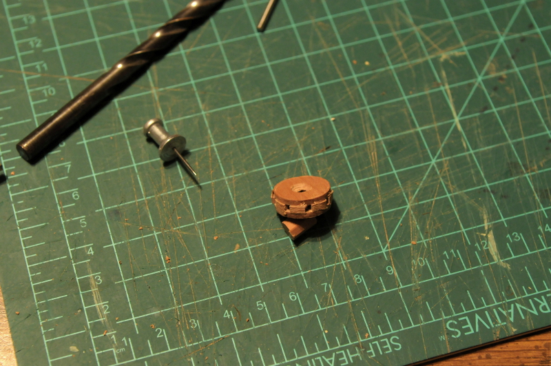
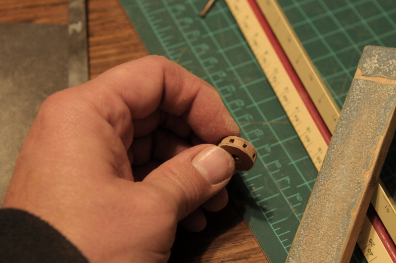
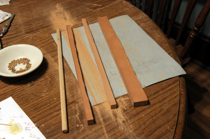
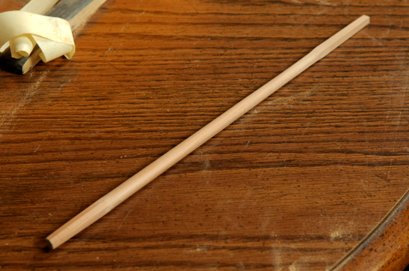
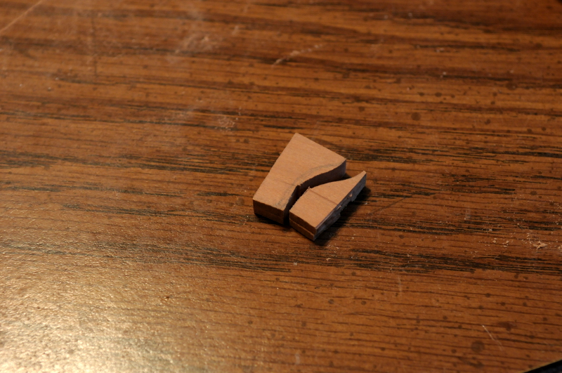
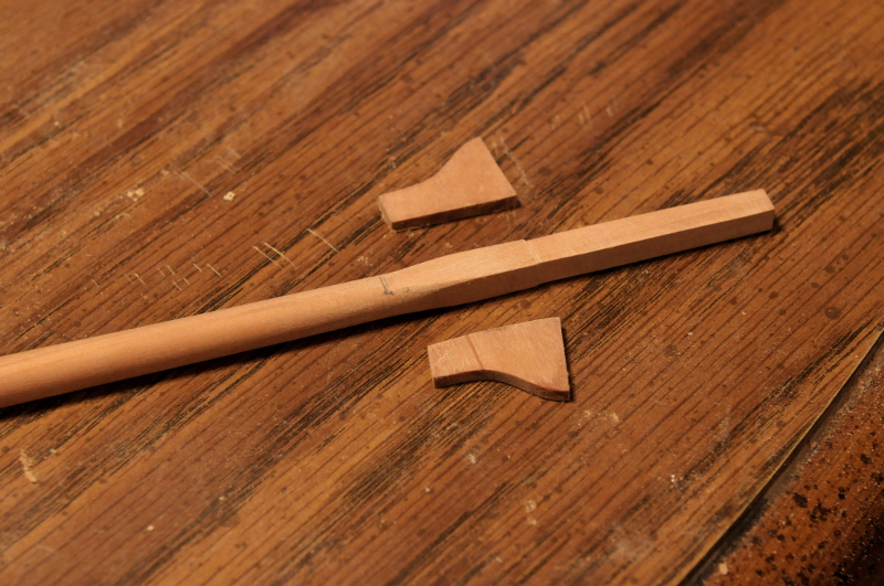
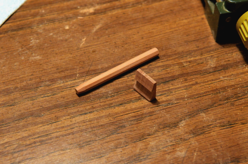
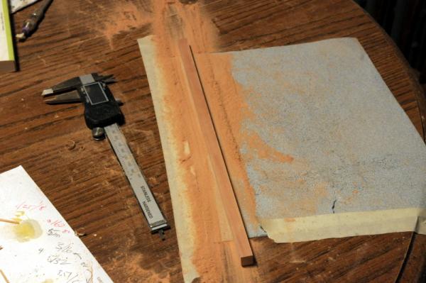
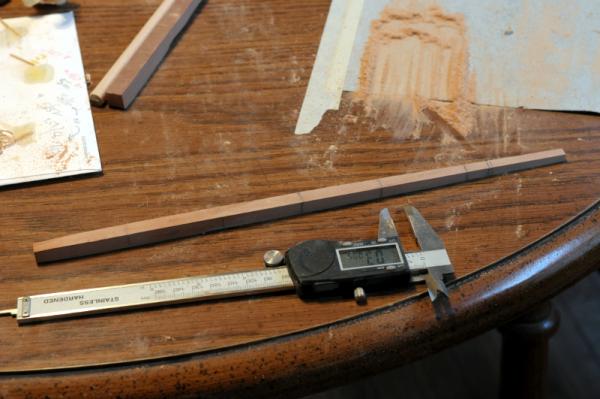
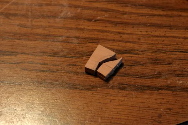
I've worked on the mast and the capstan. First the mast-- On the left is a piece of maple that I started to round, got about 3/4 of the way there, and decided I didn't like the maple. Next to that is a piece of Swiss Pear that I cut with a jewelers saw, horrendously. I wavered far off my cut line, and this piece is too narrow in the middle to make the fore or main mast. I think I can use it for the bowsprit. Next to the right is another try at cutting a straight(er) piece of wood. This one will work. Farthest on the right is the billet of wood I am cutting these from. I know this is insane, and I should just order squared wood that is close to the size I need. I didn't want to wait, (or spend more money) but after doing this once, I will order some square wood for the rest of the masts and spars! Here is the sanding down of the piece, underway- Underhill says to taper the square to the right widths, before chamfering and making the mast round, so that's what I did. Here's the mast mostly tapered square. There's still some fat at the middle section. There are some measuring points marked. As I sanded a side, these would get erased, and I'd redraw them before moving on to another side-- The illustrations and directions I have seen for mast making are for larger, "made" masts with the cheeks, front fish and iron (or rope) bands. This will be a simple, single piece, and I'm not sure how to work the bibs into the mast and taper. This may be a throwaway trial run if it's not satisfactory. But at least I will be able to use it to set the chainplate angles when I get to those. Here's the mast mostly tapered and shaped-- Next was making the bibs. I glued two pieces together, made a rough cut with the jewelers saw, and then further shaped them with files while they were glued together-- Here they are separated-- I glued them to the mast, and filed and sanded them some more-- You can also see some work on the capstan pieces in that picture, but I better back up just a little. As with the bibs, I cut blanks for the capstan whelps-- And glued them into a block-- The block was sawed, filed and sanded to get the right profile. I also made an octagonal center post. This will extend down to the lower deck-- I glued a brass pivot point into the bottom of the post, and separated the whelp pieces. The piece with the hole will sit on the upper deck with the capstan-- My capstan is supposed to be similar to the one on the Institute of Nautical Archeology (INA) model of the US Brig Jefferson. That capstan has a different profile to the whelps than I usually see, and seems a little narrower overall, also. I don't know if mine is going to end up as nice as that one! Ron


-
Thanks, hamilton. I will show the making of the brass belaying pins at some point. I have "turned" the top portion of about 10, and have one prototype completed. I'm not sure it's going to work, but I have hopes. Ron
-
Perfect, Wayne. Thanks. Yes, no doubt there are some differences. I just don't have much info on what they might be! Ron
-
I have a question regarding the taper of the main mast (and fore mast as well) for my Oneida. In Lees book The Masting and Rigging of English Ships of War 1625-1860, he gives a chart (page 2 chapter 1) showing the amount of taper relative to the partners (which would be the point of widest diameter) at 6 points along the mast: Heel, First Quarter, Second Quarter, Third Quarter, Hounds, and Head. However, I haven't found a diagram of a mast that shows those points. Please excuse this crude drawing, but this shows where I've interpreted (guessed) the measuring points to be, with the lower end of the hounds marking the end of the segment that is divided into quarters. My question is: should I use the bottom of the hounds (as I have shown), or the mid-point, or the upper end where the top would sit, as the measuring point for the Hounds? And a bigger question, is my assumption that the quarters consist of the portion of mast between the partners and the hounds correct? It's not going to make much difference which point on the hounds I use, but I'm just curious now. (However, If the quarters should be different--such as the quarter points between the head and heel--that would really change things.) Thanks for any help, Ron
-
Thank you, Ben. Elmer, I hope you enjoy building the Oneida. Every version I have seen is different, and it is very interesting to see everyone's interpretation. I am currently working on making the first section of the main mast, and I'll post some progress pictures soon. I could be making the capstan, or the bowsprit seat, or any number of other things, but for some reason I want to make that first section of the mast. I don't know why. Ron