

catopower
-
Posts
1,597 -
Joined
-
Last visited
Reputation Activity
-

 catopower got a reaction from Keith Black in Tiny Spar on 17th Century English Yacht
Allan, sorry, I should have made it clear that the photo was of a contemporary model. By the way, I don't think the rigging was removed, just the flags.
Druxey, thanks for identifying the model and providing the link! How did you recognize and find it from the photo I uploaded???
Robert, druxey, wefalck, that's interesting about the unusual Dutch block. It's different from what I'm seeing on this model, but it does seem to serve the same purpose.
The reason for my query is that I'm building Woody Joe's Charles royal yacht kit, which is apparently roughly based on this unidentified contemporary model that druxey provided the link to. The person who did the development work for this kit, the late Mr. Kazunobu Shirai, wrote a book about building the model. He wrapped the spar in the head edge of the sail. That's clearly not what I'm seeing on the museum model.
I managed to translate a bit of the book's text where he mentions that this was a Dutch practice, as everyone here has pointed out.
Dr. PR, I'm thinking the club is, as you say, is probably laced to the head of the sail. I looked for mention in Landström's book, but couldn't find anything. Do you have a page number?
These are from Mr. Shirai's book...
Clare
-
catopower got a reaction from Keith Black in Tiny Spar on 17th Century English Yacht
Thanks friends for chiming in on this subject.
I must apologize for not being more responsive, but I lost power in my house on Saturday morning when neighbor's yard people trimmed a tree and downed a power line, causing a power surge that knocked out service to several houses and burned up a lighting fixture in my house (Fire Department had located it). Just got power restored today, though possibly temporarily. I actually have no Internet still, except from some limited wifi I can piggy back onto (like right now).
Again, power's back, at least for the time being, and more importantly, light, HEAT, cooking appliances, refrigerator, and did I mention HEAT???
I'll try to follow up on your comments about this strange little spar soon!
Thanks again!
Clare
-
catopower got a reaction from Keith Black in Tiny Spar on 17th Century English Yacht
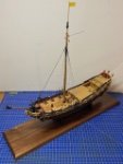
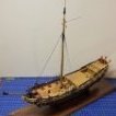
Can anyone tell me what the little spar is called that appears at the head of the jib and staysail on this English yacht?
Also, does anyone know how it's attached to the sail and to the halliard? I can makes some guesses, but I'm hoping someone has something definitive.
I've looked in various rigging references, but haven't been able to find any info.
Thanks in advance!
Clare
-
 catopower reacted to jwvolz in Mounting Benjamin W Latham
I simply used two brass rods through the keel. It is plenty strong enough and I think it looks good.
-
catopower reacted to Roger Pellett in Mounting Benjamin W Latham
In its mounted condition, the model’s waterline should be level. If you have the drawing that you used to build the model simply draw a line parallel to the waterline shown on the drawing. Draw lines perpendicular to the line that you just drew and measure the distance to the keel. Buy two pedestals that meet these dimensions.
If you don’t have the drawings set the model up temporary supports with the waterline level. Measure up just like you did above.
Roger
-
catopower reacted to Capt. Kelso in Starting a build log with half built model
Not all build logs are created equal! I've seen build logs posted after the initial build was started. It's a good way to get feedback.
-
catopower reacted to ccoyle in Starting a build log with half built model
Any stage of progress is fine.
-
catopower reacted to Peter Joyce in Lynx by Peter Joyce - Panart - 1:62 - Baltimore Schooner
Plate 2, Part 3: Cat-Davits
The cat-davits themselves are included on the laser-cut 5mm sheet and do not need to be carved as the instructions say. In some cases I think carving from wood would have been a better choice, but the cat-davits work well with plywood as it looks assembled from separate boards. In the blister pack, there is also a bag containing 2 pulleys, 2 brass rings, a copper band 24 small eyelets and two sizes for brass wire (this is from memory, your results may vary). There is a similar bag listed in the manifest, but the contents differ slightly. In any event, if you're making this model, look for the bag with the 2 pulleys.
I drilled a hole in the top of the cat-davit and then widened it with a file to allow room for the pulley and some movement room. The pulley is affixed with a brass nail through the center. I did not pre-drill a hole as I thought it might be too big and allow the nail to move, so I very carefully pushed it through making sure it aligned with the center of the brass pulley. Once the nail was well-set, I filed the ends of it flush with the board.
The plans show the ends of the davits chamfered, so I used a file to chamfer the ends.
To create the hole in the hull, I located the placement on the plans and measured from the porthole astern of the hole. I cut and filed, test-measuring with the constructed cat-davit. Once both holes were cut, I put the 1x1mm walnut from the package in Plate 2 Part 1 above around the outside of the hole.
Finally, I trimmed the base of the cat-davit that goes on the deck to the proper height to sit flush on the deck. This may have been a symptom of my deck sweeping upwards at the bow.
-
catopower reacted to Peter Joyce in Lynx by Peter Joyce - Panart - 1:62 - Baltimore Schooner
Plate 2, Part 2: Hawse-Holes
The hawse holes are fairly straightforward, however there are a couple of considerations. On the plans as well as the original drawing in Chapelle, the hawse-holes break the plane of the fender rail. However, for whatever reason the deck on my model rakes up slightly at the bow and the anchor lines must go on the deck. I don't know if I did something wrong in putting in the deck, but the time has passed to correct it if I have. I did notice in the photo on the front of the box, the hawse-holes appear above the fender rail, so that may be a compromise and in my model it is. The plates are on the 2mm laser-cut board and do not need to be carved as indicated in the instructions.
To place them in the correct location, I measured from the plans and drilled from the deck side as low as possible and then placed the plate over the hole.
-
catopower reacted to Peter Joyce in Lynx by Peter Joyce - Panart - 1:62 - Baltimore Schooner
Plate 2, Part 1: Bowsprit
I'll be changing the nomenclature for my posts for a bit. The instructions and plans each have numbered parts and I will be using that to title the posts, using one reply for each part listed on the instructions. The first is the bowsprit. This is also where a great deal of guess/investigation work happens for the parts. The first segment of the bowsprit is made from 8mm dowel and attaches via an 8x8x15mm block on the deck. The kit include 2@8mm dia. dowels from which the masts and that bowsprit are made. Laying out the masts I determined that the shorter of the two dowels will be the larger of the two masts and the longer dowel will be the shorter mast and the bowsprit.
The kit also includes in the blister pack a small bag containing an 8x8x15 walnut block, a 6mm dia. short dowel of white wood (For part 7) and a piece of 1x1mm walnut strip (for part 3). This bag does not appear on the instructions nor in the manifest of parts, but I scoured over the instructions and didn't see any other uses for the items in the bag.
The bowsprit attaches via a tongue and groove which you carve into the bowsprit and the block. I opted to cut the groove into the block first so that I could mark and cut the tongue in the bowsprit. To accomplish this, I drilled a 1/8" hole 7mm back from the forward part of the block and carved from that hole to the front of the block with an Xacto. I then filed that down to expand it a bit and smooth it. I then field down the sides of the bowsprit to fit into the groove with lots of trial fittings along the way.
To attach the next section of the bowsprit, the first segment mush be tapered down to 7mm dia. I dry-fit the assembly to the hull and marked where the bowsprit piece emerged from the bow. I wanted the taper to start there and not at the portion that was inside the deck. I wrapped that part with blue painters tape (a lot of blue painter's tape) and used the Scary Drill (Electric) as a lathe and narrowed it down with sandpaper to 7mm, dry-fitting it to the fitting. Note that the fitting is one of the square pieces with two dissimilarly-sized holes cut from the 5mm thick sheet that held the spine.
The next segment is created from 4mm dowel, cute to 170mm and tapered down to 3mm. I used the same method for tapering, ensuring that only the portion of if that extends past the fitting is tapered. This is affixed with a small piece of wood, noted as 2x3 walnut. I did not find this piece and used a bit of scrap and glued them together.
Finally, the dolphin striker (not mentioned in the instructions, but included in the detail diagram) which is made form 3mm walnut dowel and tapered to 2mm. It also gets filed down to have a tongue and is affixed with two brass nails. I pre-drilled holes in the piece, but not in the dowel. Unfortunately while trying to drive the nail, I bent the first one (you'd think I'd know by now) and split to wood slightly. It is like that now, with only 1 nail because it covered both hole when it bent, so I may re-build this piece if I have some dowel left to do so.
Below pictured is the completed (for now, there's another part detailed in a later step) bowsprit without the wrapped thread to show the joining piece.
-
catopower reacted to Peter Joyce in Lynx by Peter Joyce - Panart - 1:62 - Baltimore Schooner
Part IV: Bowsprit Passage
The next and final step for this plate before moving onto specific parts was the passage hole for the bowsprit. I procrastinated on this and did a lot of sanding of the hull in the meantime. I was intimidated by drilling a hole in the bow and had visions of the drill smashing up all the hard work I had done. The instructions say simply "Make a hole for the passage of the bowsprit with a 6mm bit. Then, use a round file to enlarge the diameter to 8mm." There accompanies a diagram, but it's just a drill bit going through the bow so I won't include it here. Eventually I had to stop procrastinating and just drill the damn hole.
I opted to carve away a bit of the outer planking to give myself a surface to place the drill bit and then I built up, starting with a 1/16" (1.6mm) hole using a pin vise. To find the location of that, I measured up 4mm from the bobstay piece where it meets the hull and marked that. I worked my way up to 1/8" (3mm) using the pin vise, but that was as far as I could get with that tool and I had to switch to the Scary Drill. I used that up to 1/4" (6.35 mm) at low speed. It turned out much less scary than the vision in my head of the bit catching an edge and smashing my hull to pieces.
As per the instructions, I then expanded the hole to 8mm using the dowel as a guide. Below is the end result.
-
catopower reacted to Peter Joyce in Lynx by Peter Joyce - Panart - 1:62 - Baltimore Schooner
Yep Chris, that is absolutely true. As I’m discovering, there are a bunch of laser-cut parts that don’t appear on the plans and I’ve had to figure out what goes with what in my own little mystery novel. It boggles my mind that they haven’t added “(note: lumber for this step not included, please see wood sheet #3)”. As a first-time builder it’s a bit disconcerting. They took all that time to create the pieces but didn’t update the xeroxed instructions?
Thanks for reading!
-
catopower reacted to chris watton in Lynx by Peter Joyce - Panart - 1:62 - Baltimore Schooner
I would guess that the manufacturer updated some of the parts from wood strip to laser cut, but have never updated the instructions to tell you this. It is a kit that has been on the market for decades.
-
catopower reacted to Peter Joyce in Lynx by Peter Joyce - Panart - 1:62 - Baltimore Schooner
Part III: Transom, Deck and Portholes
Planking completed, I moved on to the deck. One item I neglected to mention was that after removing the upper portion of the ribs, the instructions had me add three of the walnut planks on the inner portion of the ship up against the first, limewood planks. That also helped to hide my sanded glue marks from gluing the first planking on. Then the railing went on.
Transom
As I mentioned, I had to build out the stern portion of the rail. After doing that, I covered the inner part of the transom with 0.5x3 walnut strips vertically. I did this and then from the exterior cut out the portholes in the back. The instructions again told me to bend a piece of 2x6 for atop the transom, but again, I found that piece in the laser-cut plywood. (No mention in the instructions)
Now, this plywood loves to delaminate, which I had already experienced. I don't know if it's in the original gluing or a product of having sat in a box for too long, but I knew soaking it would not be the right choice so I used the evil crimping-type plank bender very carefully. I applied that and clamped it in place. Below is the completed transom
The instructions say to use 0.5x4 walnut laths horizontally for the stern of the transom, but I didn't have those. Not sure if that was neglected in the kit, there is a remote possibility that I misplaced those or used the wrong wood somewhere (not sure where I would have and I was meticulous in keeping the part together so doubt I lost it) but I didn't have it and taking stock of what I had left to do, the amount of 0.5x3 walnut lath was not going to be sufficient to complete it. I also dry-fit it and it didn't look right so I opted to order 0.5x4 walnut lath which it turns out was a spectacular idea. The wood itself is a much nicer quality than what is included in the kit. Unfortunately I ordered it from Model Shipways out of Australia and I am in the US so shipping was a bit expensive and took a while. While I waited for that, I moved on.
The Deck
Next is the deck. The instructions said to glue the deck piece on and then apply the lath. I had seen several videos and posts of people building the decks of their ships and every single one showed the deck being planked before being fitted to the model. Nevertheless I opted to follow the instructions and glue the deck in first. The deck has a sweep and a rake to the sides, so I rationalized that the reason for the decking going on after was to allow for that.
Now, here comes the big mistake. I put the dowels to be used for the masts into the holes on the deck to line the them up. Looking at the plans and Chapelle's book (Strange coincidence, I happened upon a copy of if when I wandered randomly into a used bookstore and of course had to buy it) the masts rake back about 15 degrees. User PChem530 documents this in his build log, but unfortunately I did not see any of that until later. I glued the deck down being careful to ensure the very slight rake of the deck was reflected and then moved on to the deck planking, which you can see in-progress in the glam shot I took for social media below:
A couple of things to note about this -- First, there is a gap (as PChem530 noted) between the deck and the bow, I built the jig as suggested in the instructions, and I used pins to mark the centerline of the planks. With pins placed less than 80mm apart it makes it easy to line up the planks on center to glue them down. I meticulously glued each one down rather than slop glue on the deck and place them. I didn't have the confidence to be able to do the planking in time and didn't want a crust of dried glue under my planks. The gap I filled with scrap (not pictured) but did a poor job of it and some of the planks are still "floating." We'll see how that works out.
The Portholes
I knew I had to carefully measure porthole placement against the plans because a lot of the exterior hardware depend on that placement. There is one issue, however. The chain-wales (part 6 in plate 2) do not fit between the portholes. I ended up trimming them a bit and I will get to that in the post about that part, but keep that in mind if you are following along. The chain-wales included in the laser-cut kit do not match the plans.I don't know if that's intentional to give you more material, but that's how it ended up for me. Your mileage may vary.
Finally, the instructions say to line the portholes with the 0.5x3 walnut lath. Astute readers will realize that that area consists of planking width of 1.5mm and 2@1mm for a total of 3.5mm. 3.5 >3... so that means the lath does not quite fill up the inner part of the portholes At this point I did not have my 0.5X4mm lath from down under, so I went ahead and did it. I may end up ripping it out and redoing it.
Below shows the best I could do with that gap, as well as a teaser for how it looks today:
-
catopower reacted to Peter Joyce in Lynx by Peter Joyce - Panart - 1:62 - Baltimore Schooner
Part II part 2: The Return of the Plankening
Having completed the first planking, I then spent a lot of time sanding and filling. Alas, I don't have photos of that, but my goal was to get it as smooth as possible. I felt that any imperfections in the first planking would be accentuated in the second planking. It also gave me an opportunity to hide some of the issues I had with the first planking, such as the aforementioned cracked boards and odd bends. This time I used the proper tools and was able to bend the planks more smoothly. This is aided by the fact that the second planking is done with 1x5mm walnut which bends a lot more easily. Some of the planks ended up needing a bit of a twist and it was difficult to coerce them into the right shape. I think a proper planking plan would have prevented poor planking, but in all it worked out well. I was more or less following the "Template" I had created by doing the first planking. The below image was taken recently but shows the end result.
I also went too far down on the keel with the planking, so I don't have enough keel showing. I may need to build that up a bit. In any event, the planking completed I moved on to the rest of the vessel. The next step is to cut away the upper portion of the hull framing after inserting the beams across them. The helpful diagram shows how to do that in an impossible way because you can't get the correct angle if the saw has a handle. If I had coping saw, I could have done it easily but I just laid the Xacto saw blade flat against it and managed to get it done slowly but not painlessly. I don't have photos of that process, but below is the diagram of the impossible task. Oh, remember how I said I glued the planking on? So now I had to remove the upper part of the planking which is why you might want to avoid gluing. I knew that I would have to do that when I got to this step, so I had done a bit of prep in loosening the glue and had glued only lightly with wood glue. As it turned out, the pieces snapped off easily, though it was a step I was apprehensive about.
Then came the railing. This is where the instructions begin to deviate almost immediately, a theme that is continuing and worsening. The instructions tell you to build the railings from 2x6mm walnut. My kit does not contains 2x6 walnut but does contain a laser-cut railing which I surmised to be the proper part for the job. Those are included on the sheet with the deck and a number of other pieces. I glued those on but they did not quite fit. I ended up fashioning a bit extra from the same board and attaching that. I'm not sure what, if anything, I did wrong. Below shows the addition, though this is after a few more steps
I consider three possibilities of what may have caused the shortage:
What I thought are the railings are not, but they are not noted anywhere else in the instructions or diagram I assembled the frame incorrectly. I don't know how I could have, it snaps together. The pieces are cut incorrectly. I am still unsure that this is the case, but it's all I have to go on. The interesting thing is that if the rails and deck move further towards the stern, it would help with the rake that is missing from my masts, which is a bridge I'll have to cross later. -
catopower reacted to Peter Joyce in Lynx by Peter Joyce - Panart - 1:62 - Baltimore Schooner
Part II: The Plankening
Never having done planking before, I turned to YouTube and found a number of videos instructing me in about as many ways as there were videos. I looked for a planking plan, but didn't find anything so I decided to just wing it. I will say, the instructions come with a nice illustration showing about where planks bend and where to trim, so I had an idea of what it should look like. The most important part was that the top four planks must be lined up and even as they will be above the deck. So I did those four on each side. The instructions said to put the planks in with brass nails, which will later be removed. I see that on this forum a lot, but I had no success with that. I tried with a hammer and the nail bent, I tried with a nail pusher thingy and the nail bent and the few I was able to get on took a lot of coercion and pain.
I ended up abandoning the brass nails and went with gluing the planks on and holding them in place using the binder-clip trick. I'm not 100% sure I was supposed to glue them, and in fact further steps indicate that maybe I shouldn't have, but I did it and it worked. Another mistake was the plank bender. I used the grippy one. I ended up cracking some of the boards and with some pretty harsh bends. I wish I had discovered the soldering-iron type which in later bendings worked much better.
But my progress slowed considerably at this point. I would take out the model, bend a plank, glue and place it and then let it dry and then only when I was bored and had some time. So my first planking took a few of years with on and off modeling. Partly this was due to not having dedicated place to work. I'd pull my rubbermaid container out, pull out my tools, bend a plank, and then put it away for a month or longer. Then 2020 and the pandemic came along with telework, the result of which was much home renovation. The last of the renovations included an office/hobby room for me and we were off to the races! I managed to complete my first planking a mere 5 years and 7 months after starting the model.
-
catopower reacted to Peter Joyce in Lynx by Peter Joyce - Panart - 1:62 - Baltimore Schooner
Background
My father was a model ship builder and completed a number through his life so I was always around it. He passed a while ago and I finally got around to trying my hand at it, though I wish I had done so when he was still around. Unfortunately I didn't pay that much attention when he was building as I had what at the time were much more exciting things to do. So the result now is a desire, but not a ton of skill, to carry on my father's tradition.
After expressing that desire, I was gifted the above kit in late 2017 and got straight to work, expecting it to be similar to the plastic models I had built as a kid. Boy was I wrong! But I set out nonetheless, determined to complete the model. I didn't know about MSW or many of the online resources and assumed that the plans and instructions would serve to pull me through. After all, Dad didn't have the internet when he started! I quickly started putting the hull together, pictured below (I did take a few pictures through the process, and I was going to document it for the whole few weeks it would take me to build it. However, my illusions were quickly shattered).
The hull construction was fairly straightforward, each piece was detailed on the plans and I was able to match them up by number and using that with the plans, put the hull together. After putting the hull together, the instruction was to file down some of the pieces. This was my first mistake. I pulled out my new Dremel and got to work removing way too much material. This error would not be evident for a while. What I should have done is lay some planking and see exactly how much I needed to remove to create the bow shape. (You will all be happy to know I put the Dremel away and haven't used it for this project again)
The next instruction was "The first planking has to be done with 1,5 lime-tree laths; the second with 1x5 walnut laths. Proceed from the top towards the bottom alternating every three or fours laths of the flanks to be covered." I was stumped. But that is a tale for the next post.
-
 catopower got a reaction from Scottish Guy in Cutty Sark by David Chapman - Revell -1/96 - PLASTIC - beginner's build
Hi David, welcome to MSW!
Others have given some good advice here. I'll just add that I would at least start considering how you want to mount the model. If you wait too long, it will become difficult to drill holes into the bottom of the ship safely, if that's something your stand will require. I usually use mounting pins or screws and try to plan where they will go ahead of time.
If your model has a solid hull, then screws or pins are no problem. If it is plank-on-bulkhead, you may want to reinforce the interior structure by gluing in some solid wood blocks, so screws or pins will have something to support them.
-
 catopower got a reaction from mtaylor in Cutty Sark by David Chapman - Revell -1/96 - PLASTIC - beginner's build
Hi David, welcome to MSW!
Others have given some good advice here. I'll just add that I would at least start considering how you want to mount the model. If you wait too long, it will become difficult to drill holes into the bottom of the ship safely, if that's something your stand will require. I usually use mounting pins or screws and try to plan where they will go ahead of time.
If your model has a solid hull, then screws or pins are no problem. If it is plank-on-bulkhead, you may want to reinforce the interior structure by gluing in some solid wood blocks, so screws or pins will have something to support them.
-
catopower reacted to SteveA in New builder here, understanding the different types of wood in your kit???
I looked at the Corsair instructions on the Occre website and it only shows sapelli, lime/sycamore, and walnut being supplied with the kit, same as my Occre Xebec kit. Sapelli is the brown wood with porous grain, typically used as a top finish surface in planking. Lime/sycamore is the cream colored wood used for dowels, under layer planking and decking in my kit. The thicker hardwood pieces may be dyed walnut. My kit has walnut pieces, but they aren’t colored like that. Walnut is typically used for deck furnishings, etc…
-
catopower reacted to Feymoon in New builder here, understanding the different types of wood in your kit???
Hello everyone, I'm currently building the OcCre model Corsair (1:80 scale) and it's my first ever super detailed model ship. I've been a huge fan of building dioramas and crafting terrain/monsters/miscellaneous things for my D&D group, and also I've been quite handy in assembling all types of kits from Tamiya, Revell, Trumpeter, etc. Being new to wooden plank on bulkhead models, I'm having a hard time finding anything about the identification of the types of woods generally used in these model kits. I've included a couple pictures of the wood that was in the Corsair kit and a picture of one of the pages in the IP manual/parts list. Unfortunately (or fortunately, I don't really know yet lol), the parts list doesn't include a list of how many of each type of wood was included with the kit, rather a cut list for each individual piece to be assembled. In the right column it states what type of wood to use for each particular piece but that's where I'm stumped. I don't have any idea what is what, and to make things worse there are multiple different colors/types of wood with the same dimensions. The only thing I've found online really is that most types of wood commonly used in these kits can vary wildly in color and texture, and that sucks lol. My main concern is just that I use the wrong type of wood for a particular series of parts and then later on in the build find out that I've ran out of a specific kind of material and get stuck. If anyone has built the OcCre Corsair, or can help me identify what the woods are that were included in this kit, I'd be forever grateful for your help in figuring this out. Thanks to anyone who has read this, have a good day!
Cheers, and take care <3.
-
 catopower got a reaction from Canute in Shipyard kit color to Josonja Acrylic paint conversion chart
I noticed that your first post shows Shipyard's HMS Wolf kit. Are you working on that one? I've been working on it too, though I took a bit of a break to finish up some other stuff. I got as far as making the masts and starting on the other spars. Would love to see what you're doing on the Wolf!
-
catopower got a reaction from Canute in Shipyard kit color to Josonja Acrylic paint conversion chart
Nice work on the color conversion. My only concern would be with opacity/transparency of the paints.
As you discovered the Shipyard kits include a brand of paints called Renesans, a Polish brand. They can be found online, but you usually have to order from Europe, and it can be difficult to find a seller that can/will ship internationally.
The Renesans acrylics have a slightly transparent quality to them, so you can see printed or laser-etched (burned) details through the paint. I like to use these paints for the Shipyard printed paper kits for this reason. Also, I've found that with lots of grinding and stirring, that I've been able to revive most of the dried Shipyard paint jars. But, it is a lot easier to just get new Renesans paints if you can find them.
-
 catopower got a reaction from Gregory in Hello from Seattle - looking to buy a built ship
I don't know where some people are coming up with ridiculous ideas of the value of kit built ship models. If they're well done, then they have value. The idea that they're worth so little is total BS. It all depends on the modeler and their skill, and attention to detail, and scale. If that's not the case, then many of us shouldn't even be here, myself included...
-
catopower got a reaction from mtaylor in Hello from Seattle - looking to buy a built ship
I don't know where some people are coming up with ridiculous ideas of the value of kit built ship models. If they're well done, then they have value. The idea that they're worth so little is total BS. It all depends on the modeler and their skill, and attention to detail, and scale. If that's not the case, then many of us shouldn't even be here, myself included...