Glenn-UK
-
Posts
3,175 -
Joined
-
Last visited
Content Type
Profiles
Forums
Gallery
Events
Everything posted by Glenn-UK
-
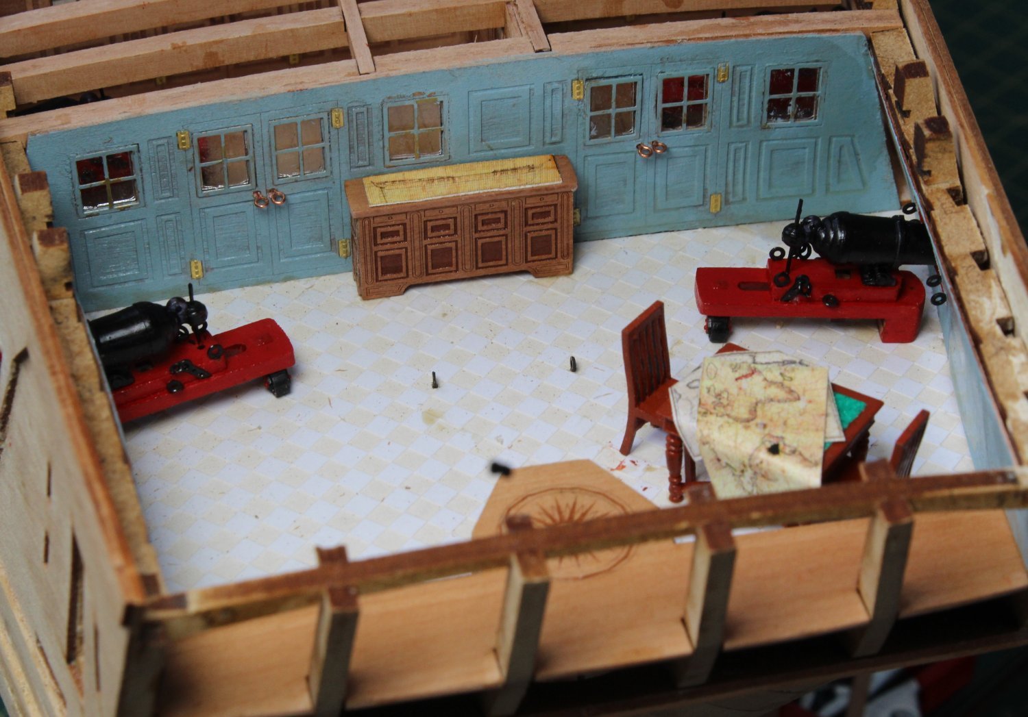
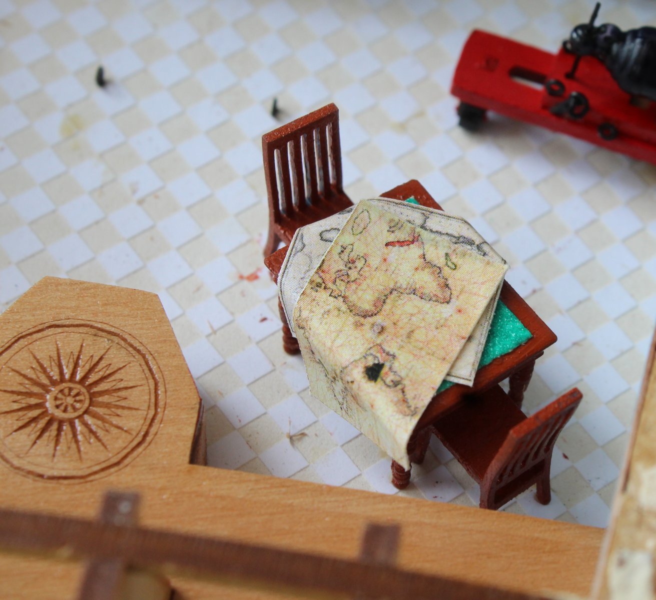
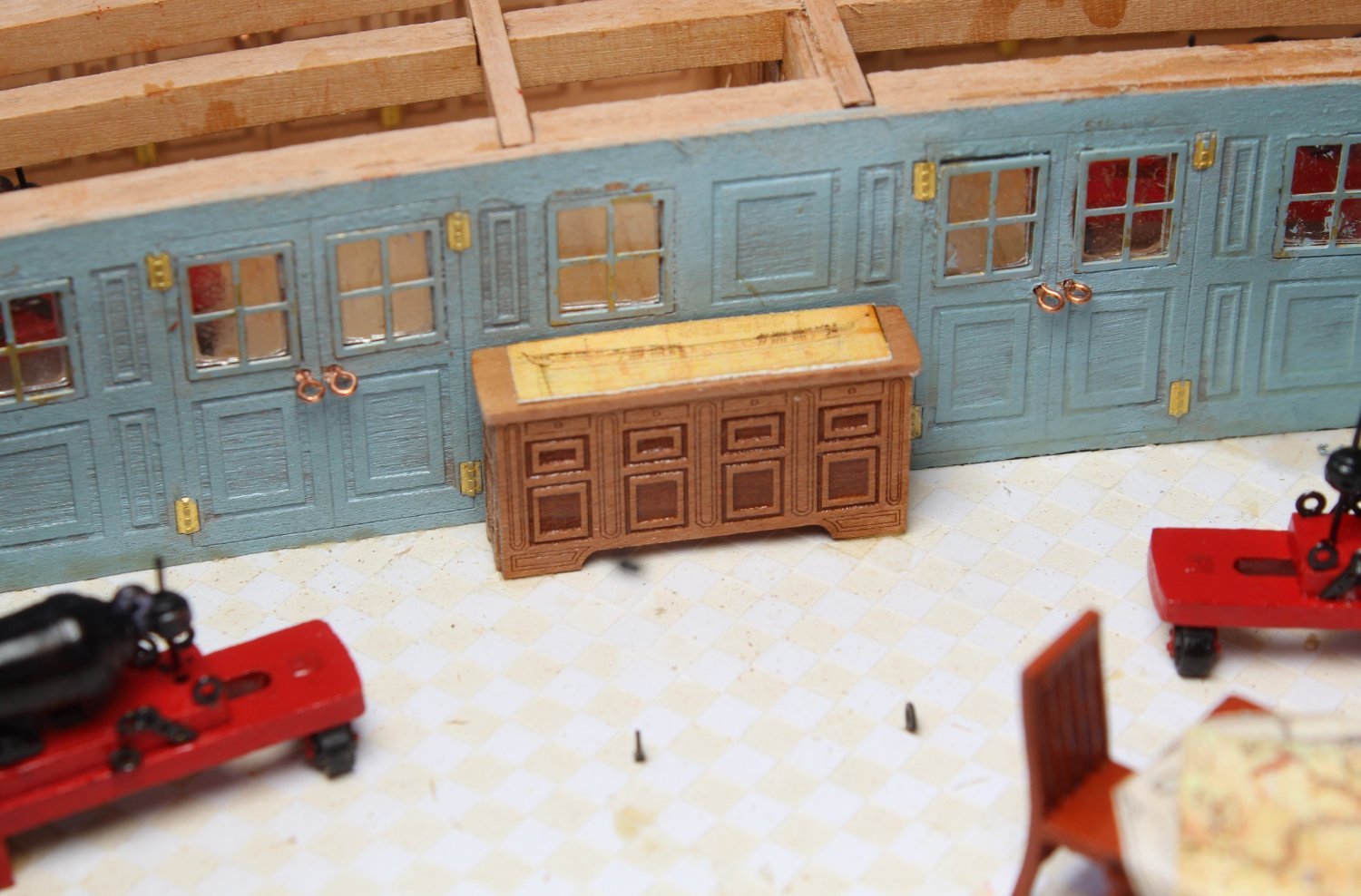
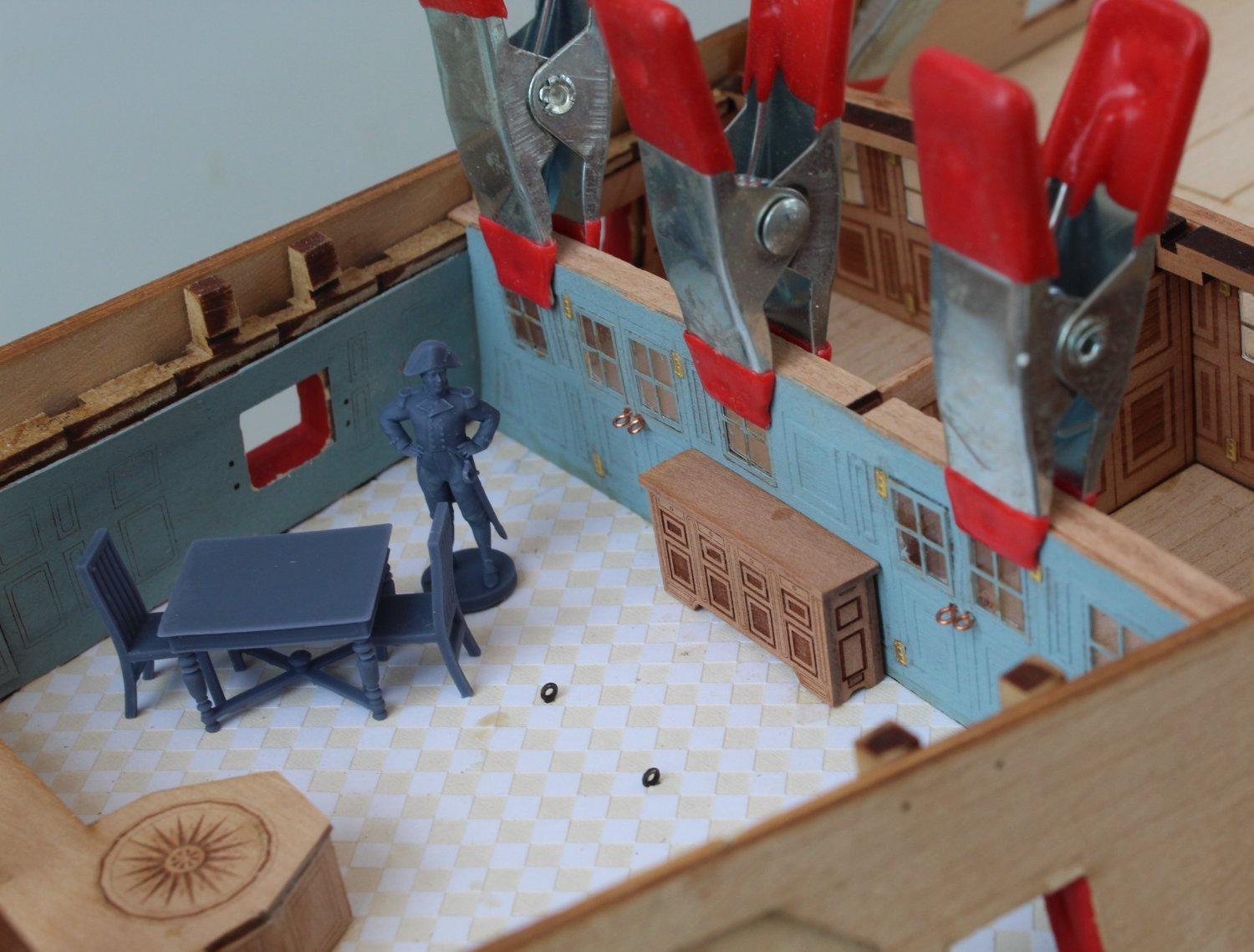
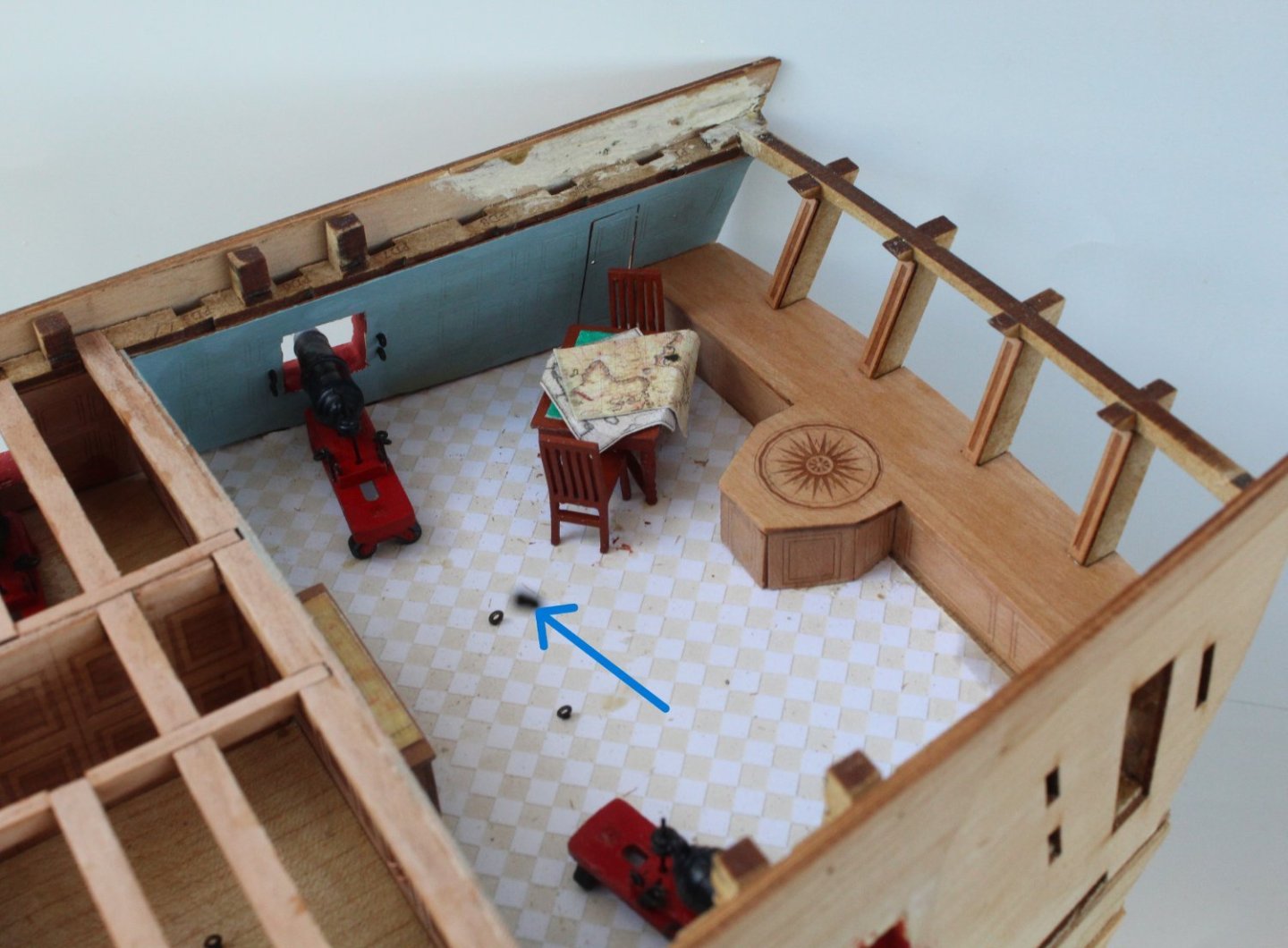
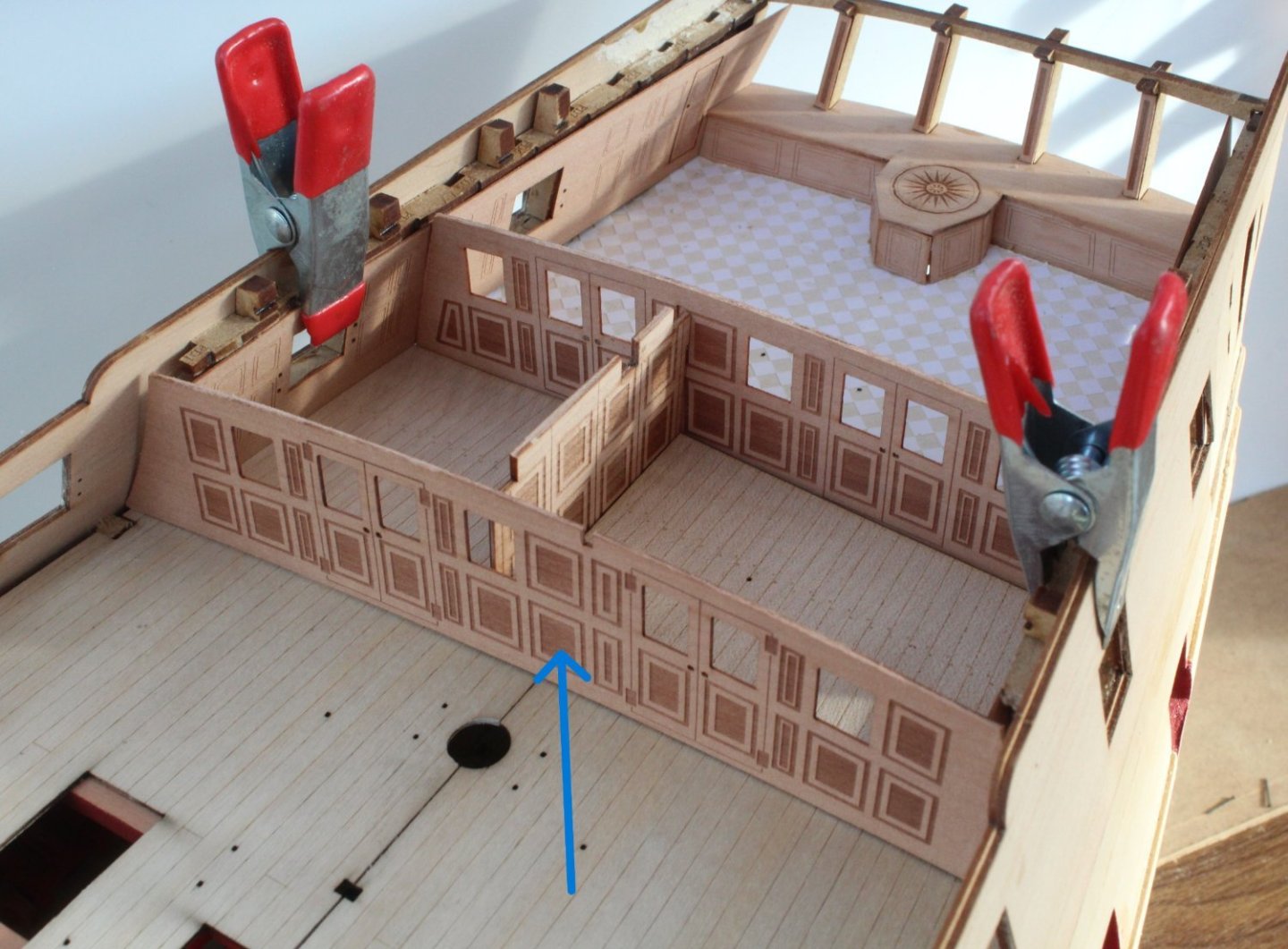
 The Return - The Captain's Cabin I have now returned from a truly memorably Blue Danube river cruise. Saltsburg was very impressive and my wife and I climbed the 144 step steps to visit Nonnberg Abbey (home of Maria Von Trapp when she was a nun). After walking getting back to Salzburg's cathedral my wife could not find her phone. In the searing 35 degree heat I ran back to the abbey bounding up the 144 stairs two at a time. Thankfully the phone was still on a pew. I then ran back to the cathedral bounding back down the 144 steps. My wife rewarded me with a nice cool banana milkshake. As can be seen in the picture below, which was taken before my epic run, I seem to have a horse on my head. The steps behind the fountain is where they sang the doe re me song in the Sound Of Music (Mirabell Gardens, Saltsburg). So this morning it is time to resume work on the Indy and the first task was to finish off the Captain's cabin. I added a green baize effect to the table top. After searching for some suitable material I ended up using a piece of sandpaper which was just the right shade of green. The various charts and maps were then cut of of the manual and carefully arranged on the furniture. Sadly my camera lens got damaged during the holiday so each picture has a black mark, as indicated by the arrow on the first photo. Despite several attempts to clean the lens the mark is still there so I have ended up ordering a new lens which should arrive int he next few days. I tried a few different arrangements before deciding on the following arrangement for the table and chairs. I opted to add the plan sheet of the Indy to the top of the cabinet. The workmanship on the cabin screen is not my best work.


- 587 replies
-
- 13
-

-

-
- Indefatigable
- Vanguard Models
- (and 1 more)
-
Nice work great work. I do like making the masts, bowsprit and yards but it will be a few weeks before I reach that stage.
- 443 replies
-
- 3
-
-
- Indefatigable
- Vanguard Models
- (and 1 more)
-
Thanks, overall I'm happy with how my Indy is looking so far.
- 587 replies
-
- 1
-
-
- Indefatigable
- Vanguard Models
- (and 1 more)
-
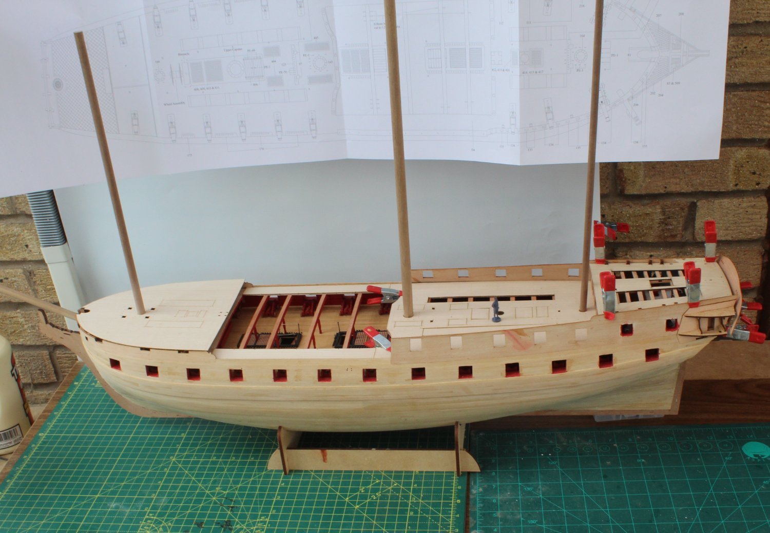
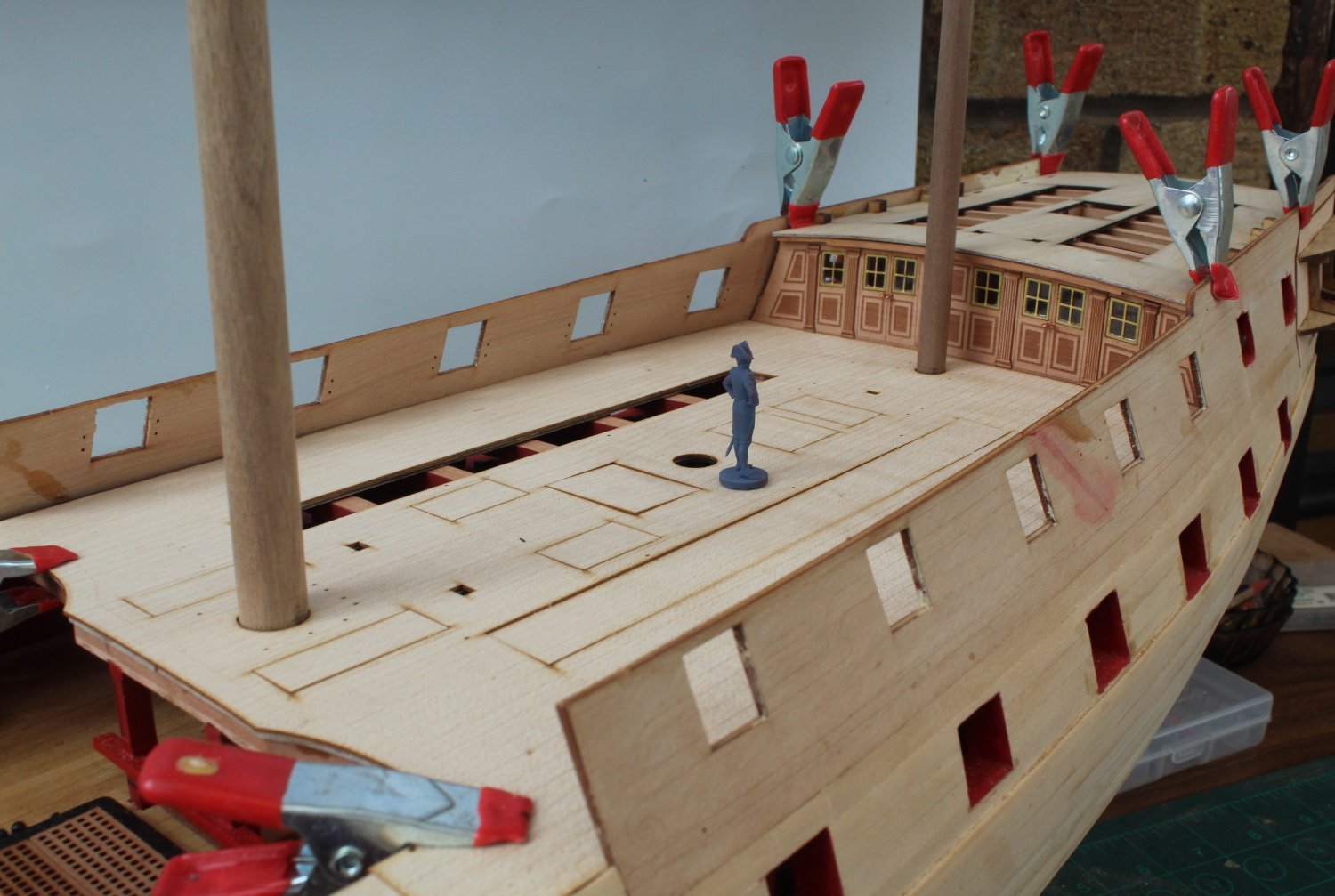
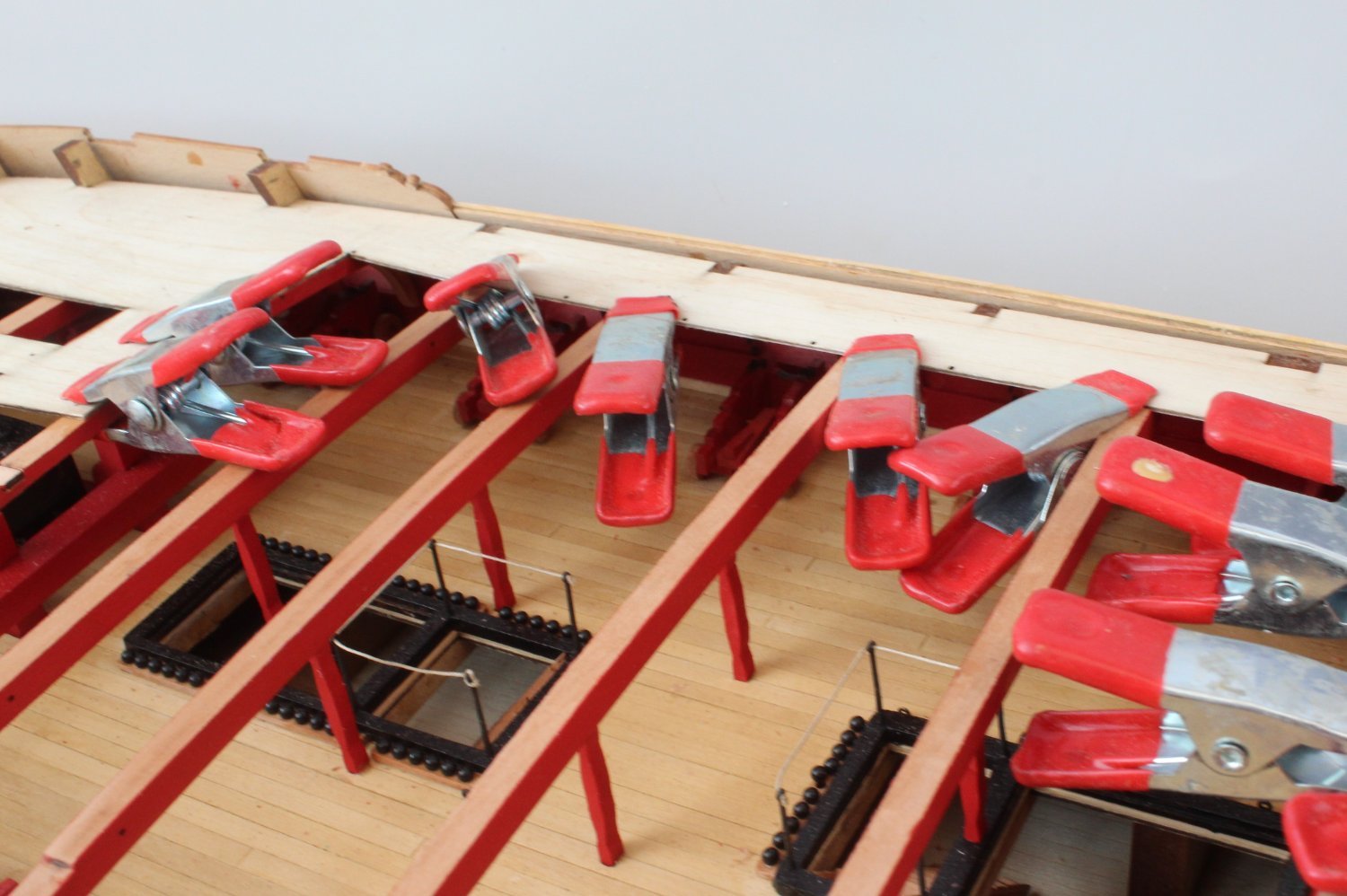
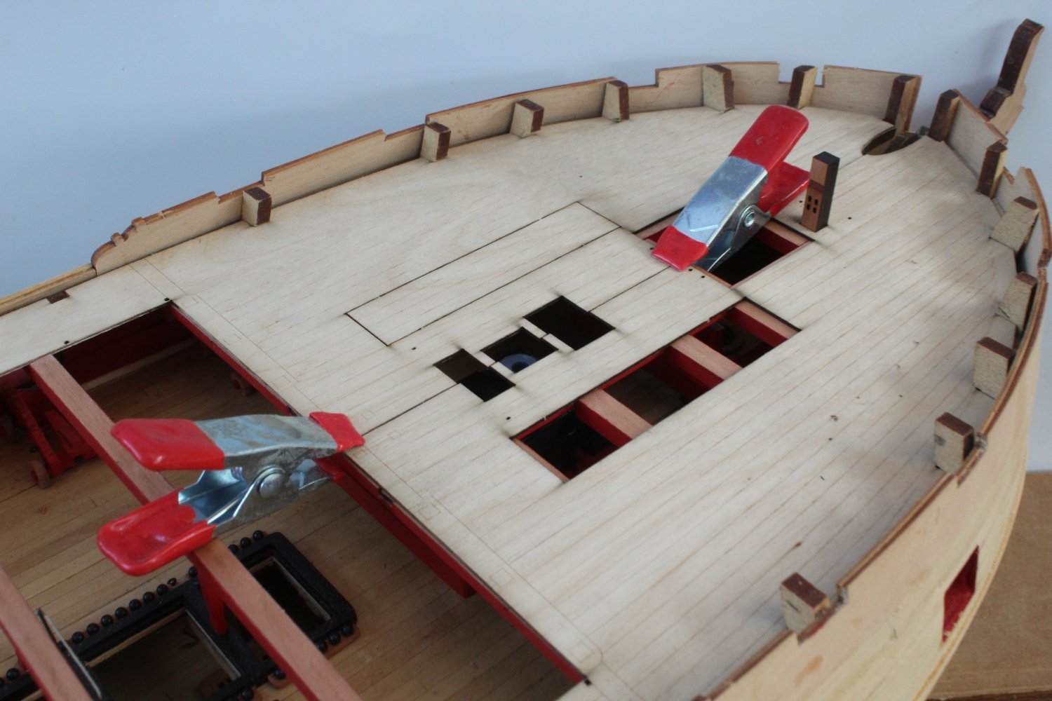
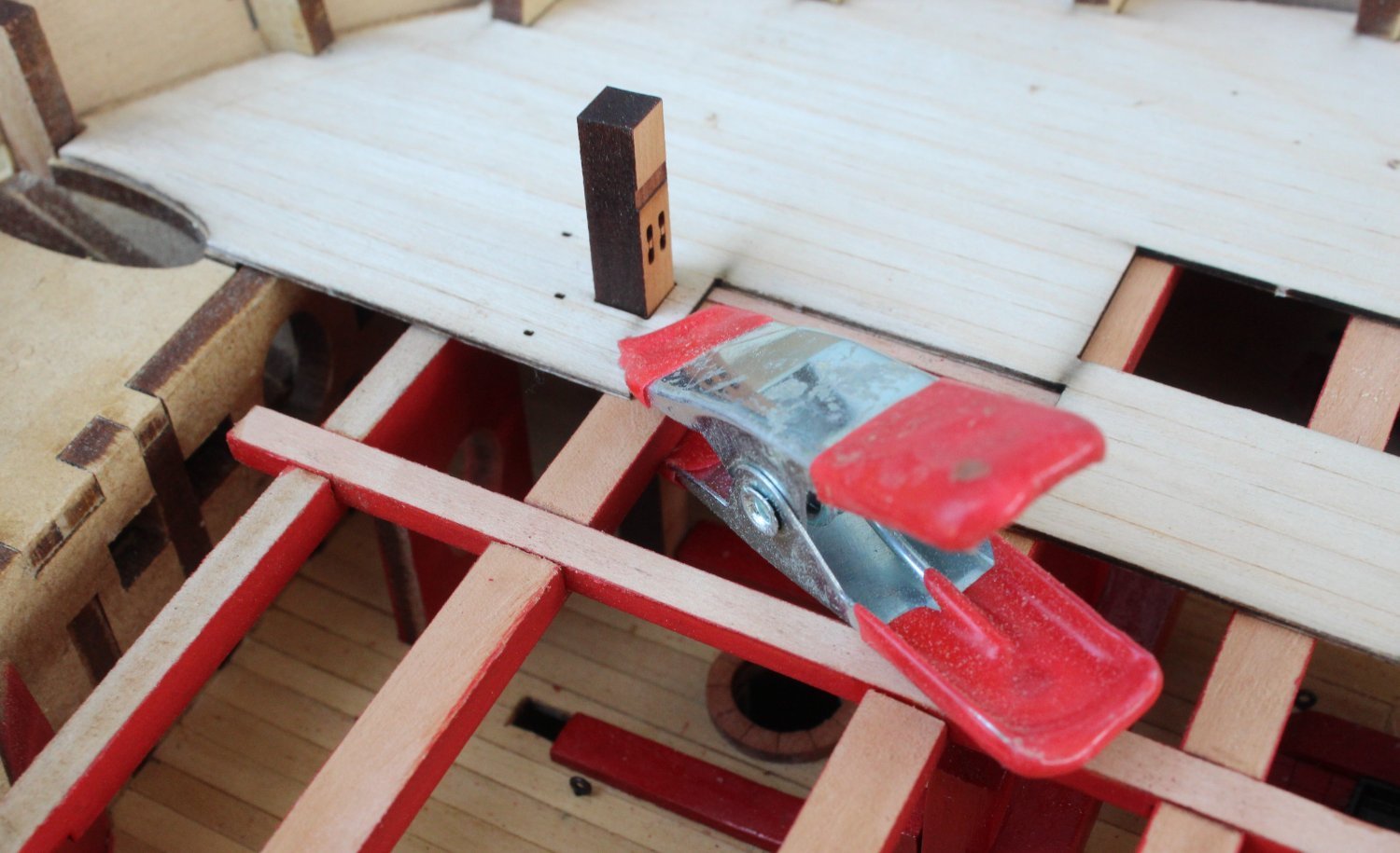
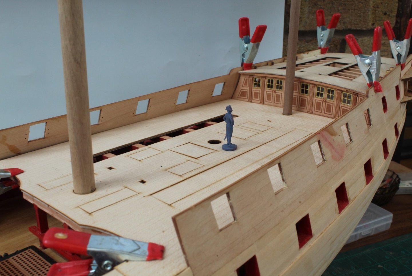
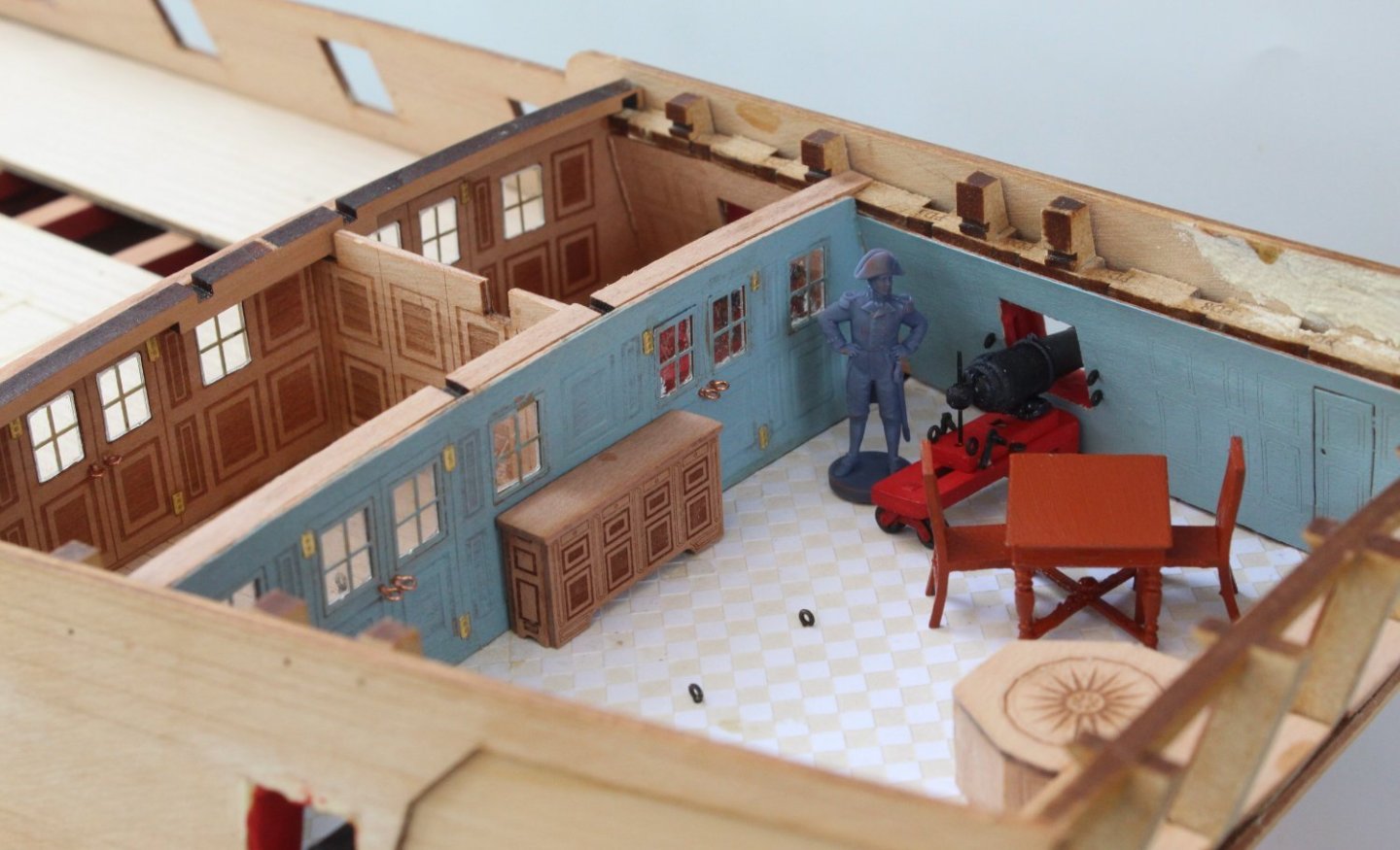
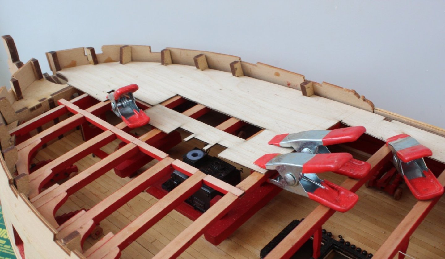
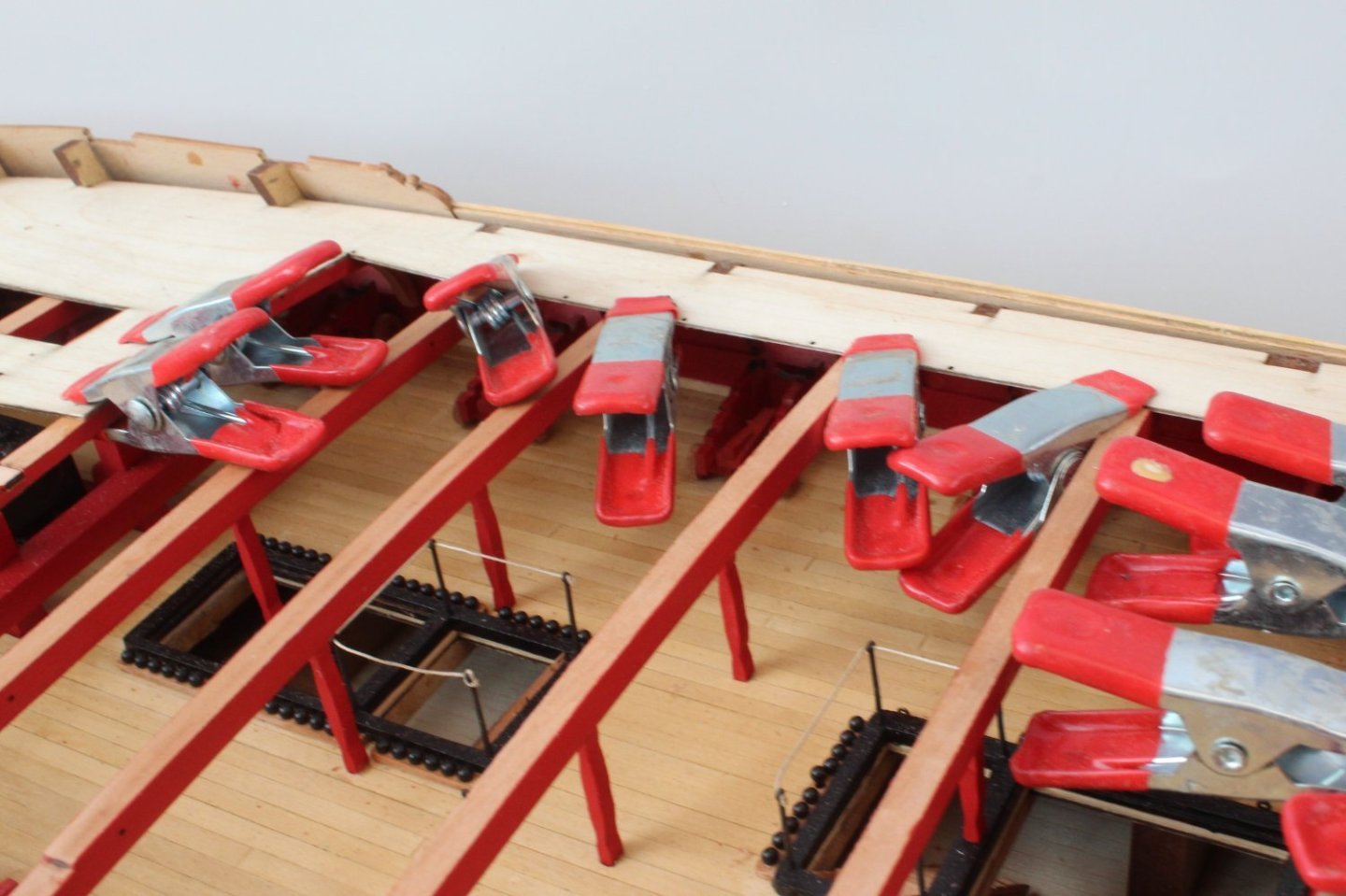
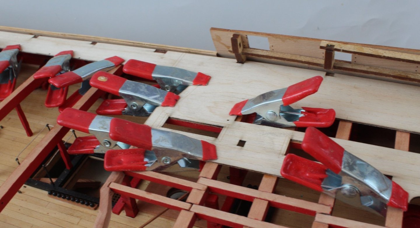
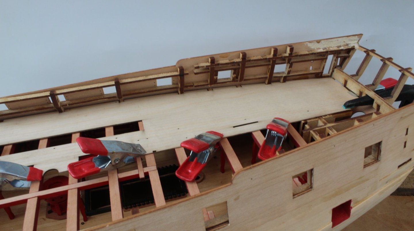
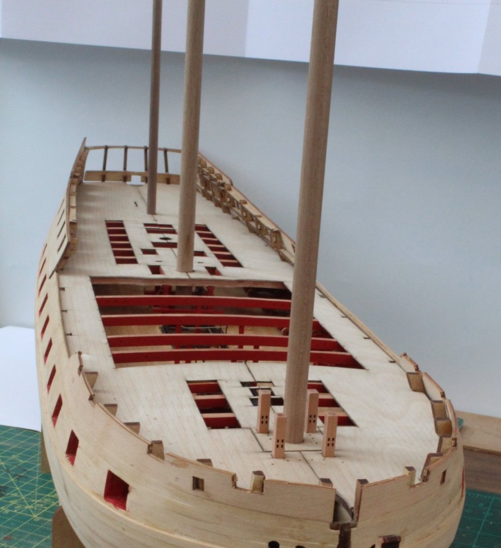
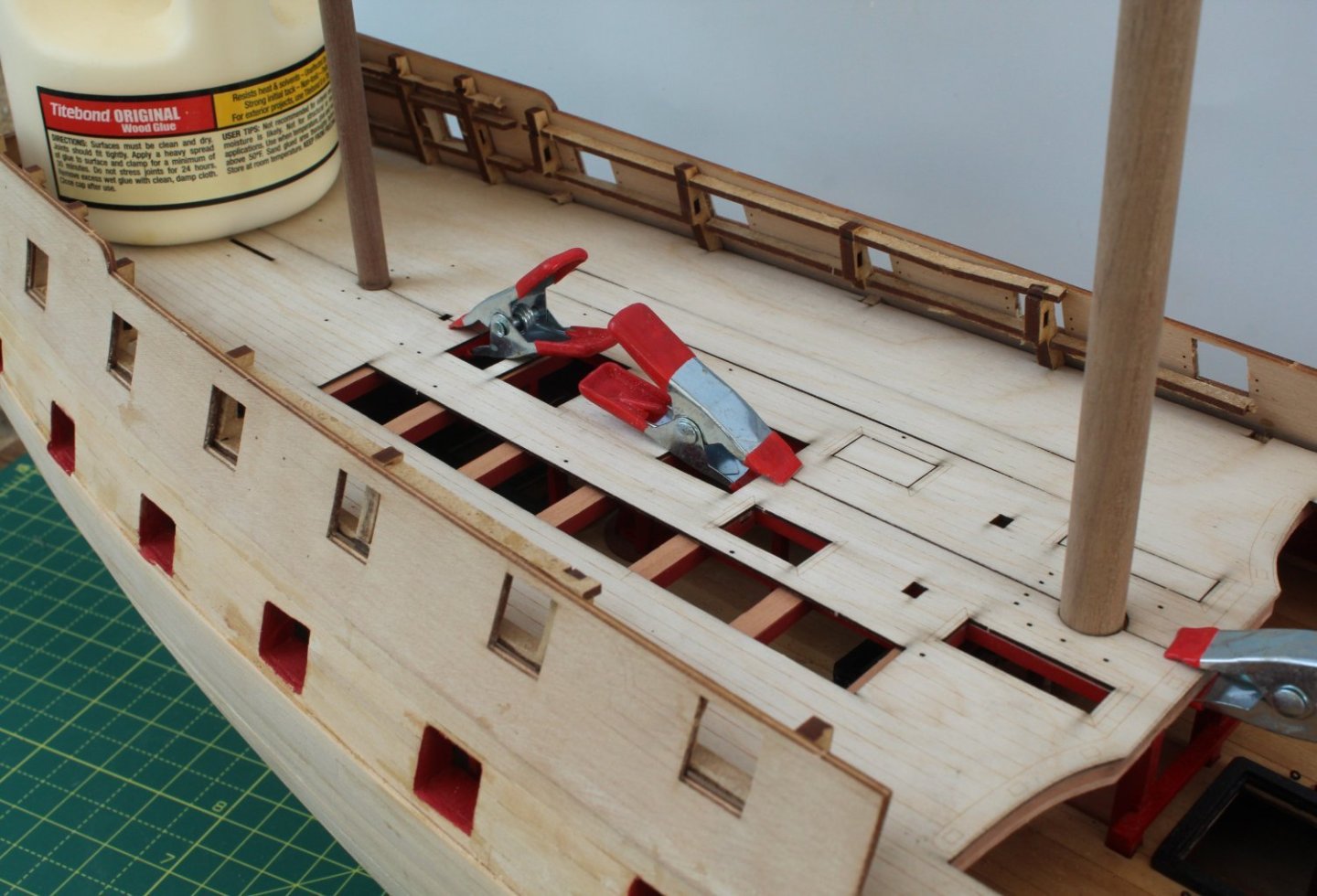
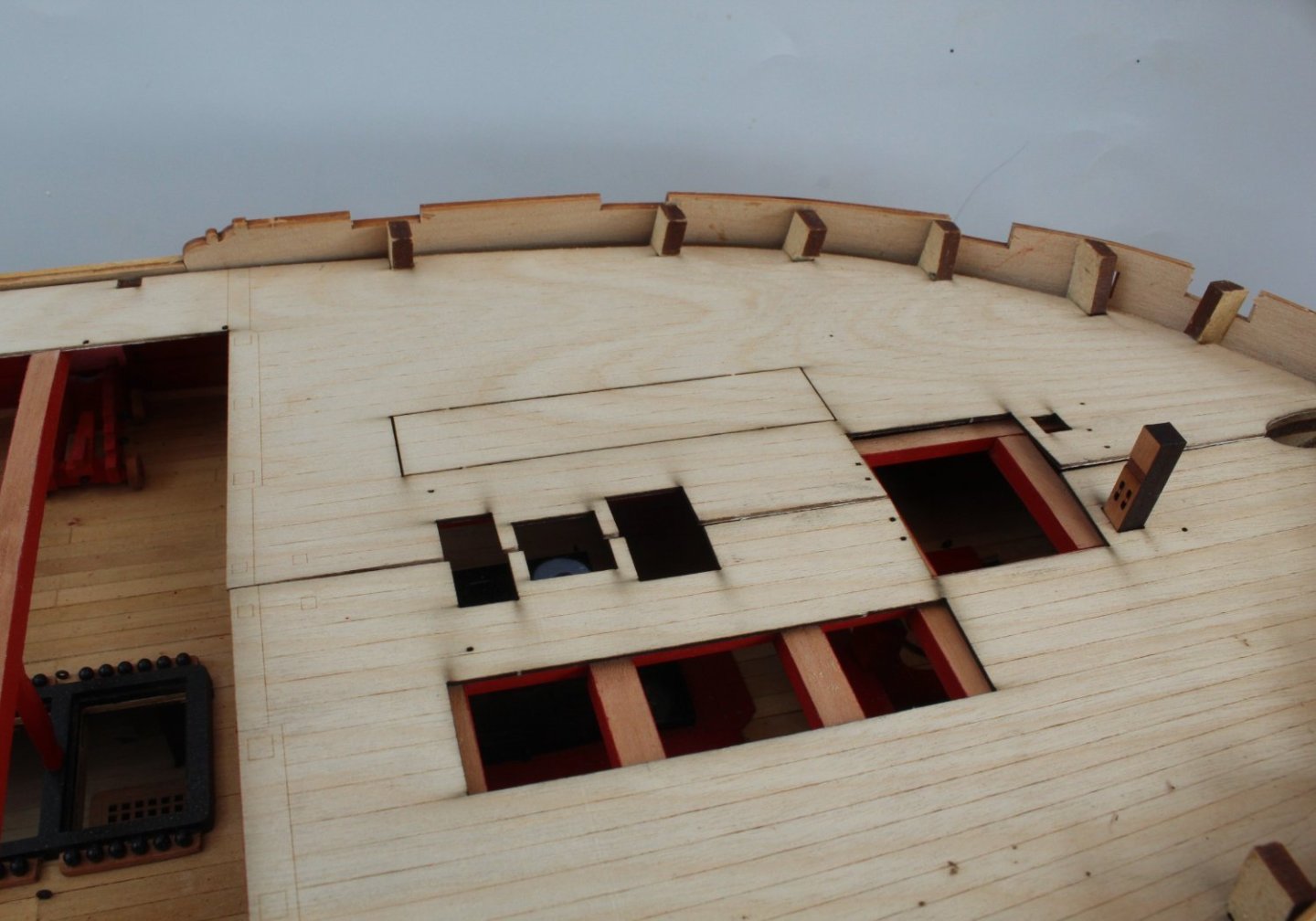
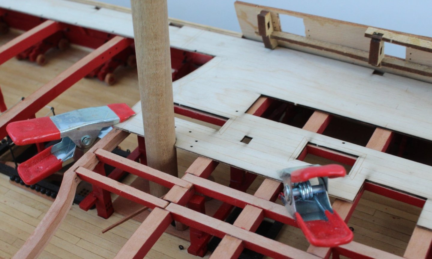
As I wait to leave home for our next holiday I decided I would take a few pictures of the Indy, showing how she will be left in my absence. I have dry fitted the poop deck beams and placed the poop deck base pattern in position. It was a great fit. The quarterdeck, walkways and forecastle pear patterns have also been placed in position (dry fit), noting the bulkhead ears still need to be removed from the forecastle area which is why it is sitting proud. With the various decks in place a check was made that the bowsprit, foremast, main mast and miizzen mast would all locate properly, which they did. The view to the cabin area looks good. I will add some pear fillers where the screen meets the bulwarks to hide the gap. The captain has been inspecting the work and seems reasonably happy with the progress to date. I am using clamps to hold the dry fitted decks in position. I hope that, when I return from my holiday, they will have retained the required shape which will make the gluing process a bit easier. The quarter galleries have also been dry fitted, and although not shown in the final photo, the top and middle stern patterns have also been checked and everything seems to line up. On my return from holiday the first task will be to complete all work related to the poop deck area.

- 587 replies
-
- 8
-
-
-
- Indefatigable
- Vanguard Models
- (and 1 more)
-
Looking at the drawing the pivot seems to be the screw adjustment the end of the barrel, opposite to the mizzen end.
- 587 replies
-
- 1
-
-
- Indefatigable
- Vanguard Models
- (and 1 more)
-
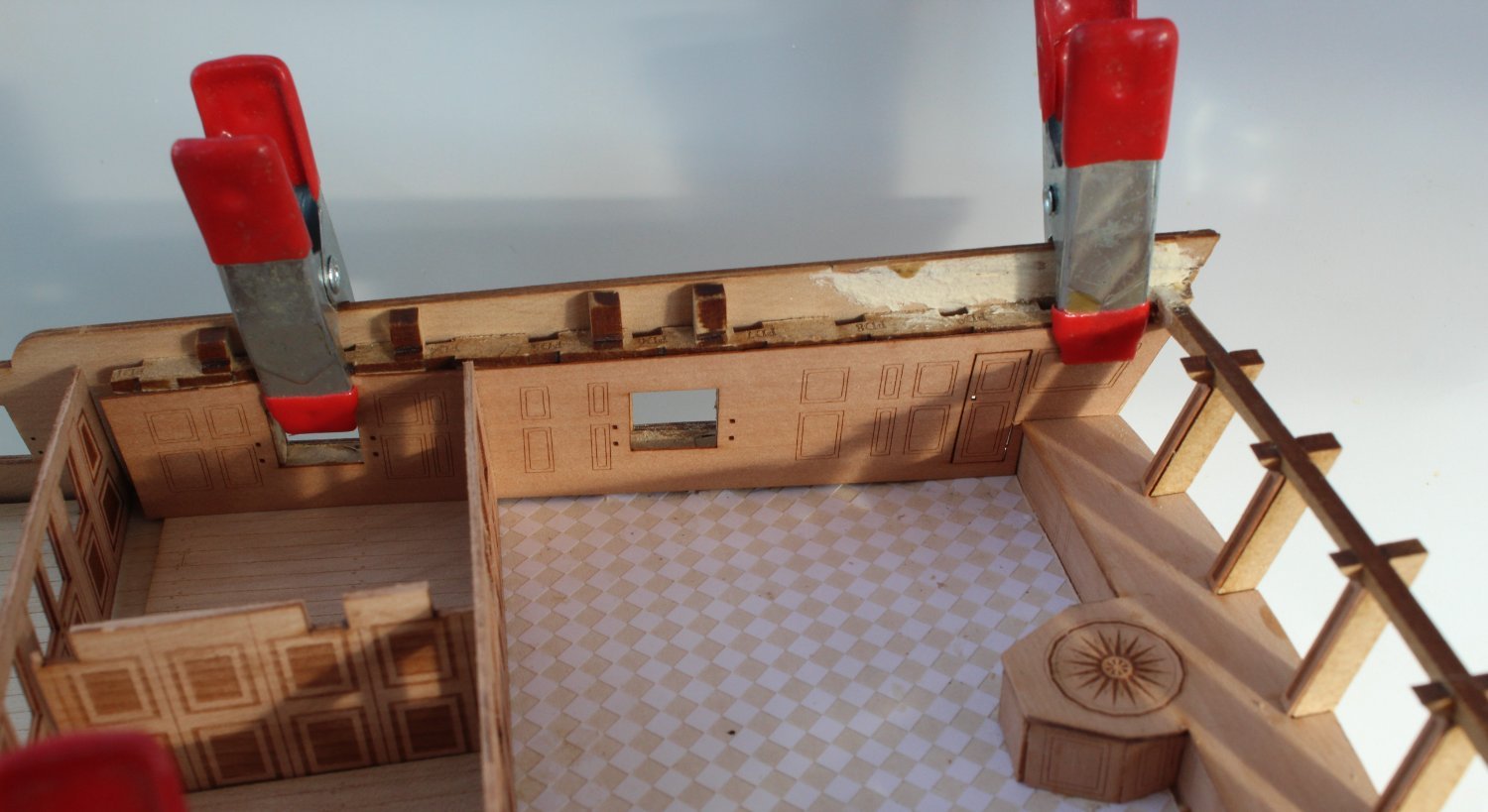
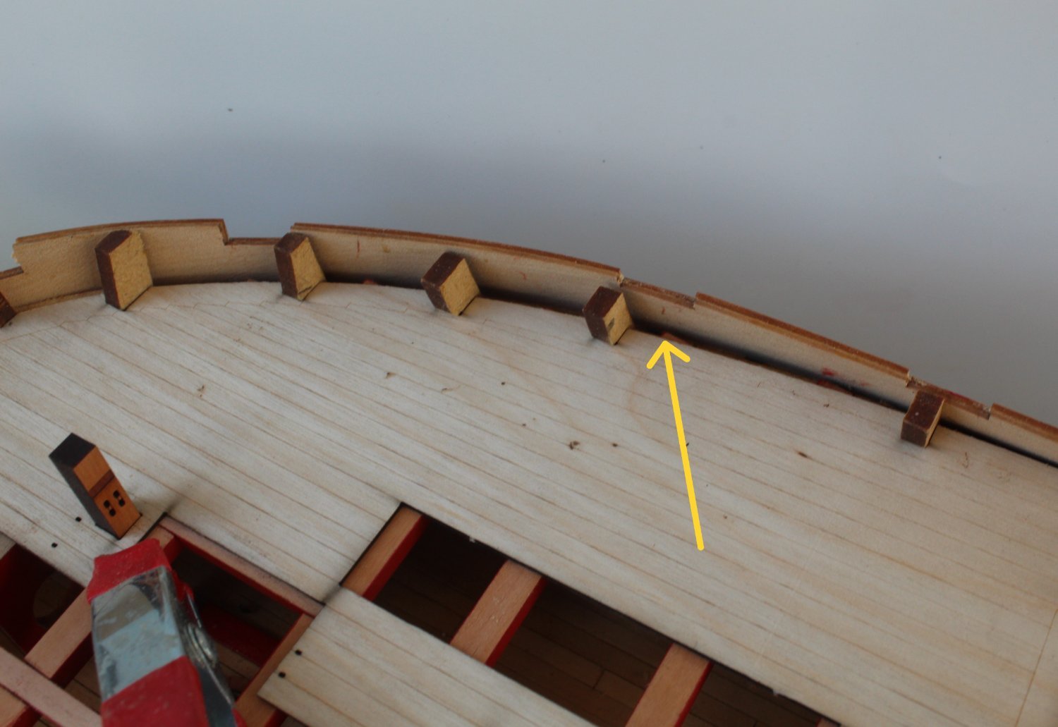
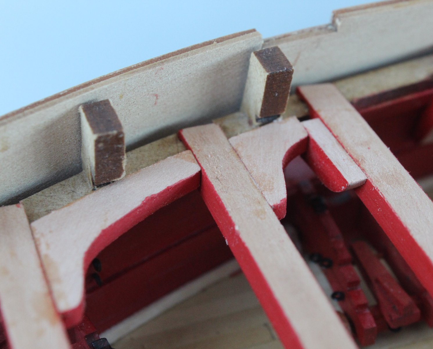
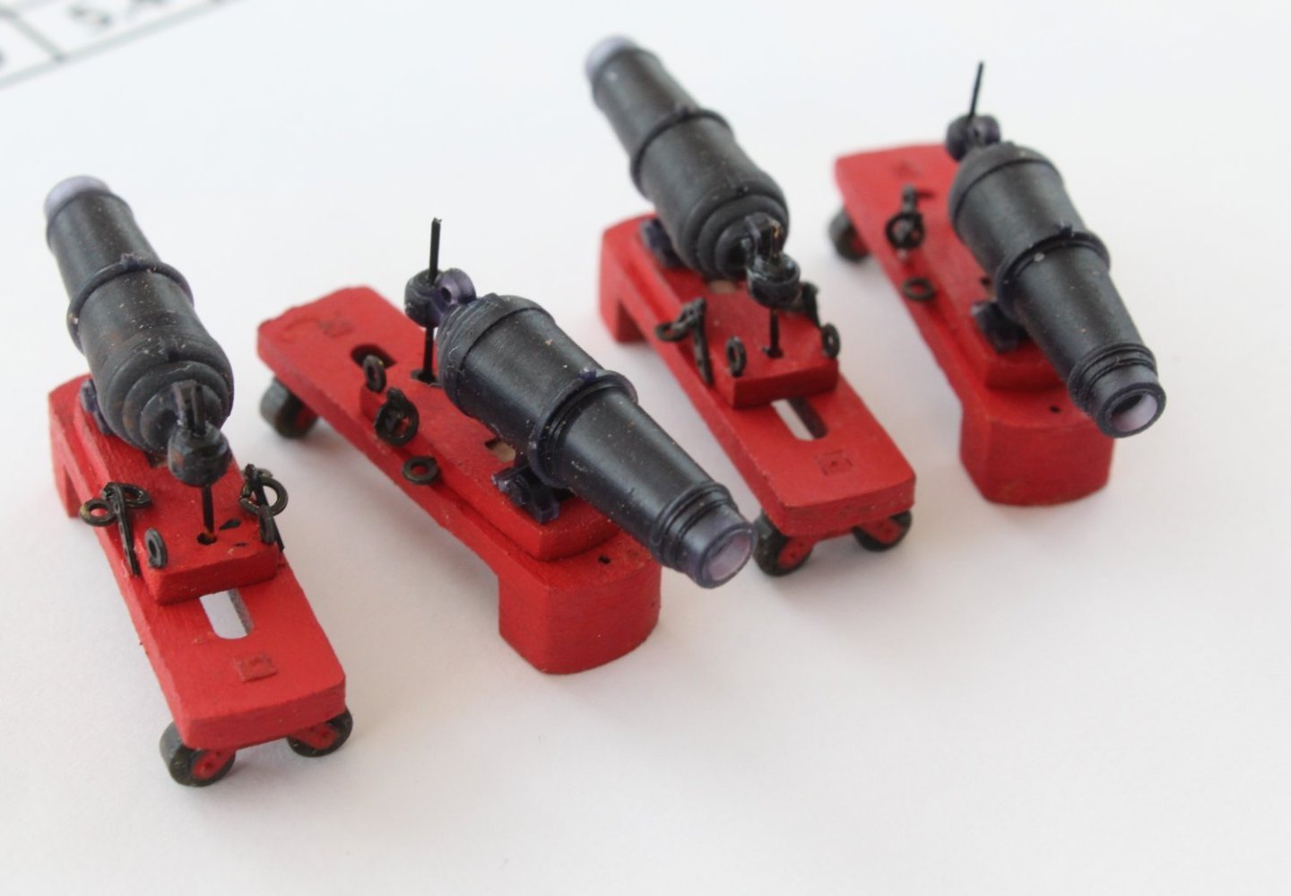
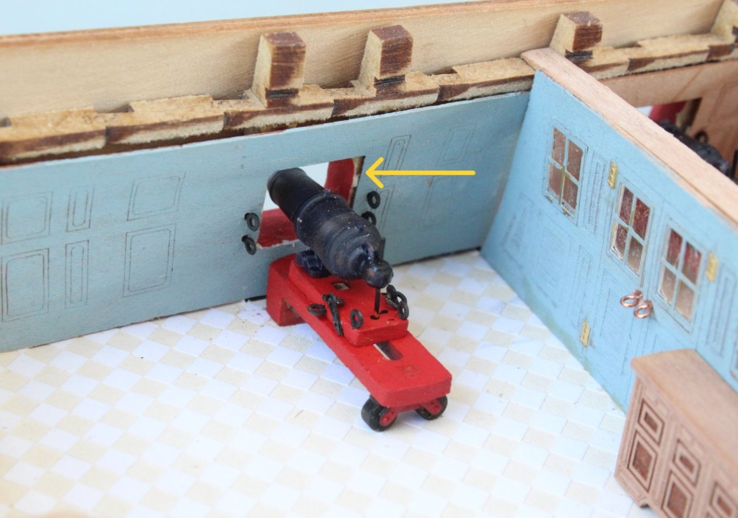
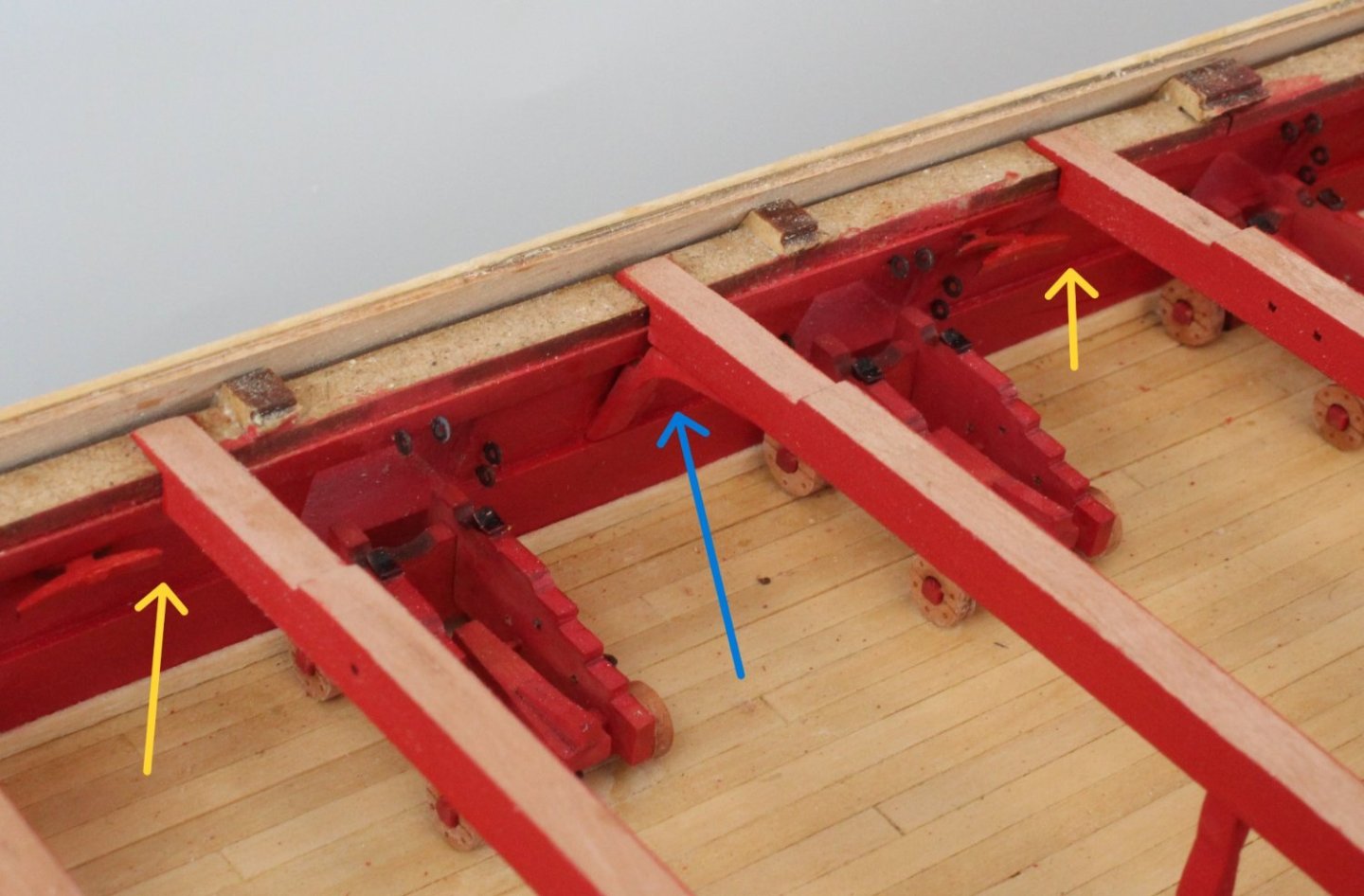
Carronades The 4 off carronades have been fully built and I am really pleased with how they look. They also look nice when added to the cabin. As can be seen in the next photo there is a slight error with how I aligned the inner bulwark pattern (yellow arrow). As it will not be seen once the poop deck has been added I am not going to worry about it. The captain is a little bit happier with his cabin. The table and chairs have been oil painted. I have no idea how long it takes for oil paint to fully dry. They were painted over 24 hours ago and they are still not dry. I will probably add a green baize to the table top before I add the maps and charts. I am now going to be AWOL from the shipyard until a week on Saturday as my wife and I are travelling to Budapest tomorrow for another river trip as we enjoyed the one last month so much. This time down we cruise down the Blue Danube, visiting places such as Bratislava, Esztergom, Durnstein, Vienna and Salzburg. My wife loves the Sound of Music so she is really looking forward to visiting Salzburg. I am looking forward to visiting Durnstein whose castle imprisoned Richard the Lionheart in 1192 after he was shipwrecked on his return from the crusades.
- 587 replies
-
- 10
-
-
-
- Indefatigable
- Vanguard Models
- (and 1 more)
-
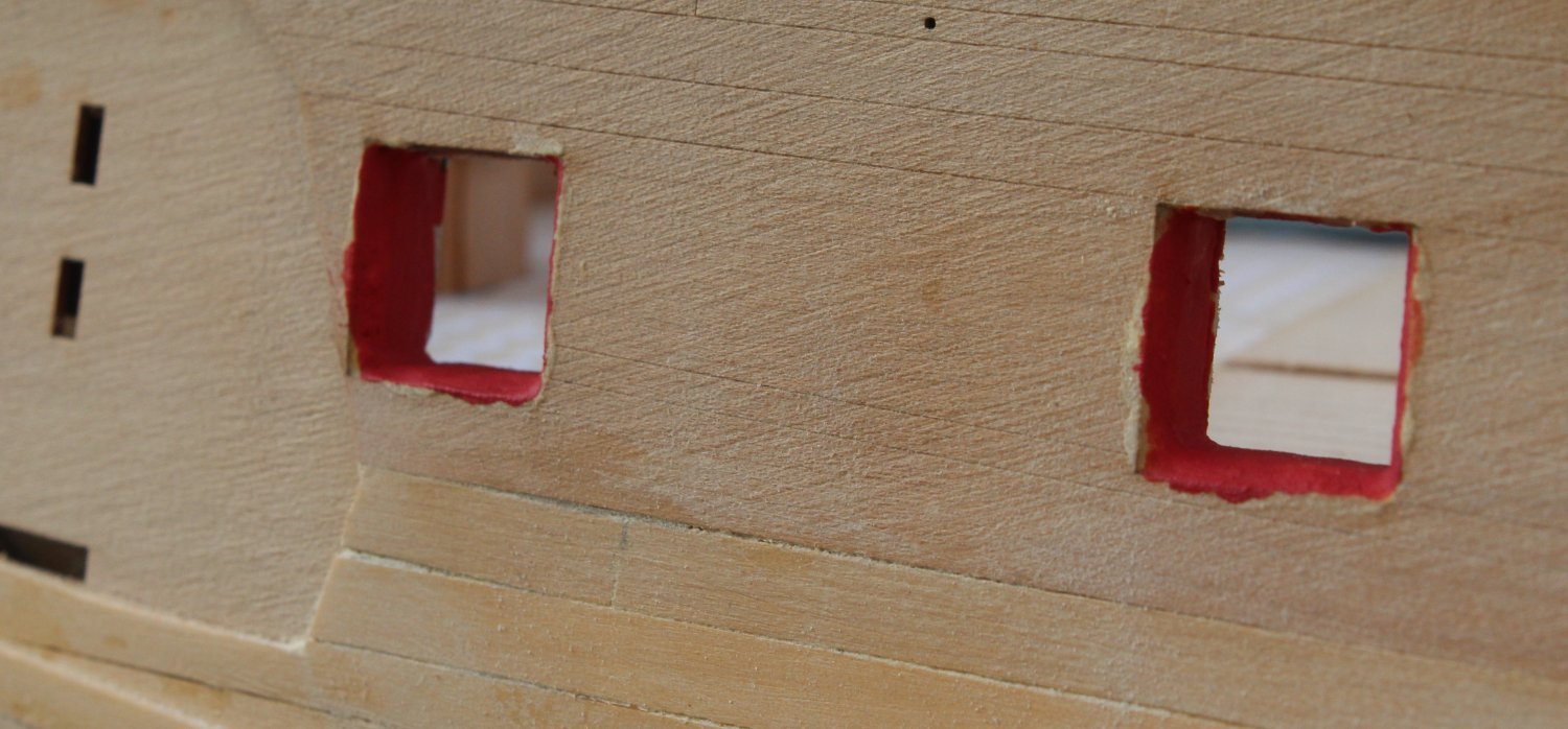
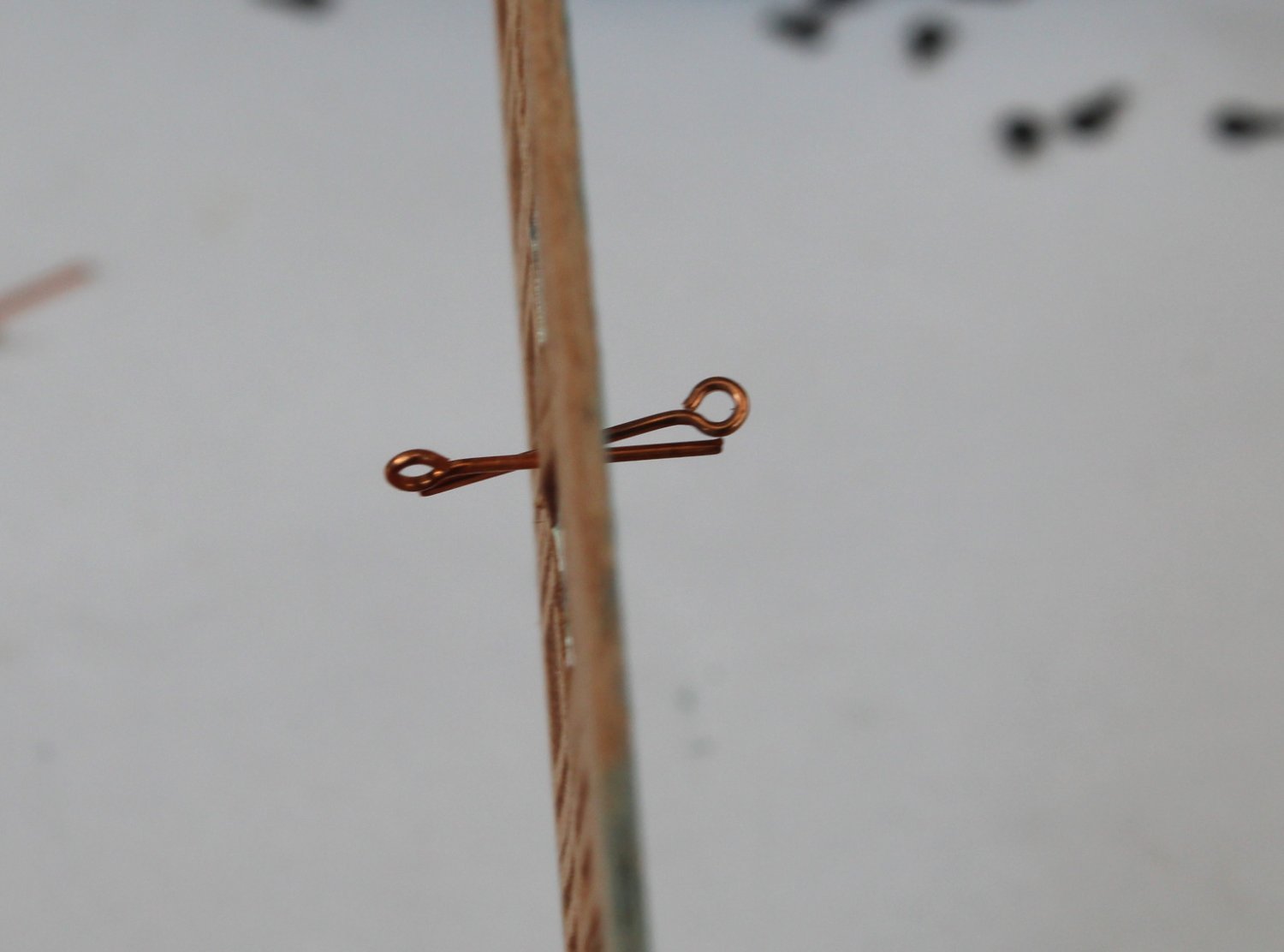
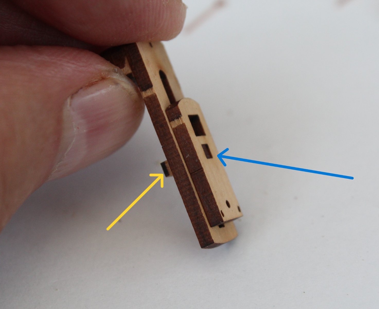
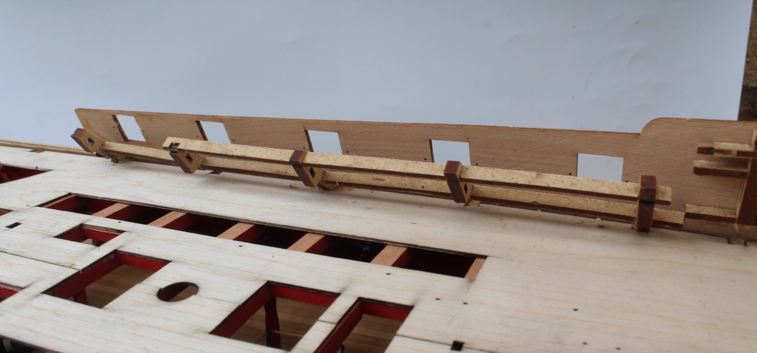
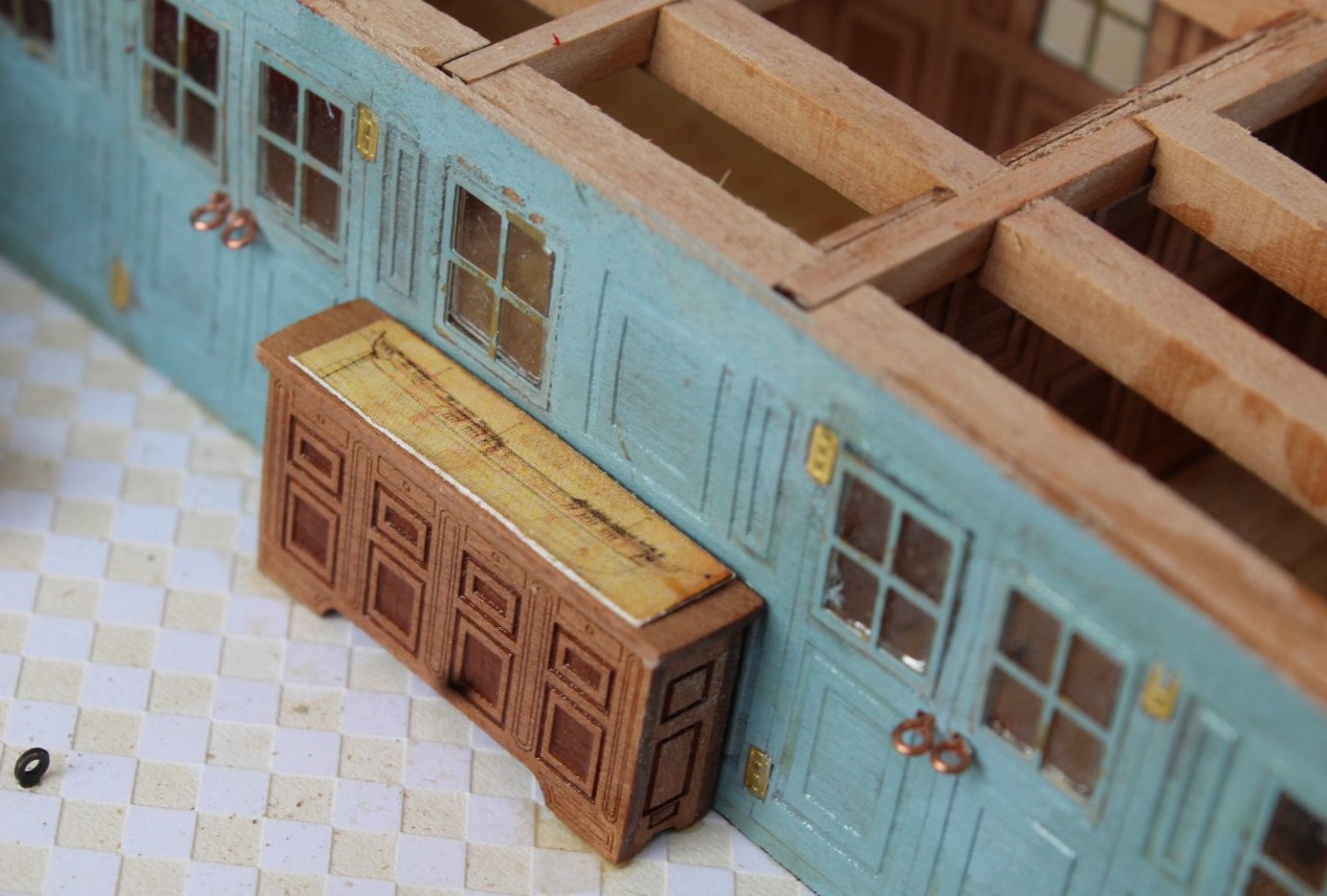
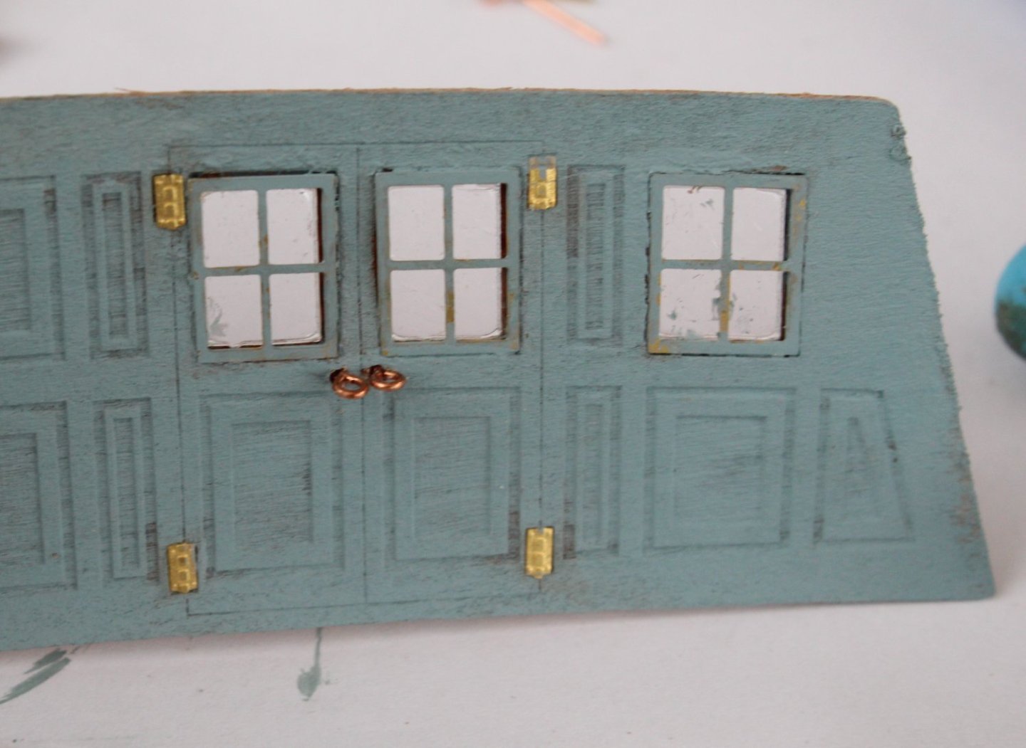
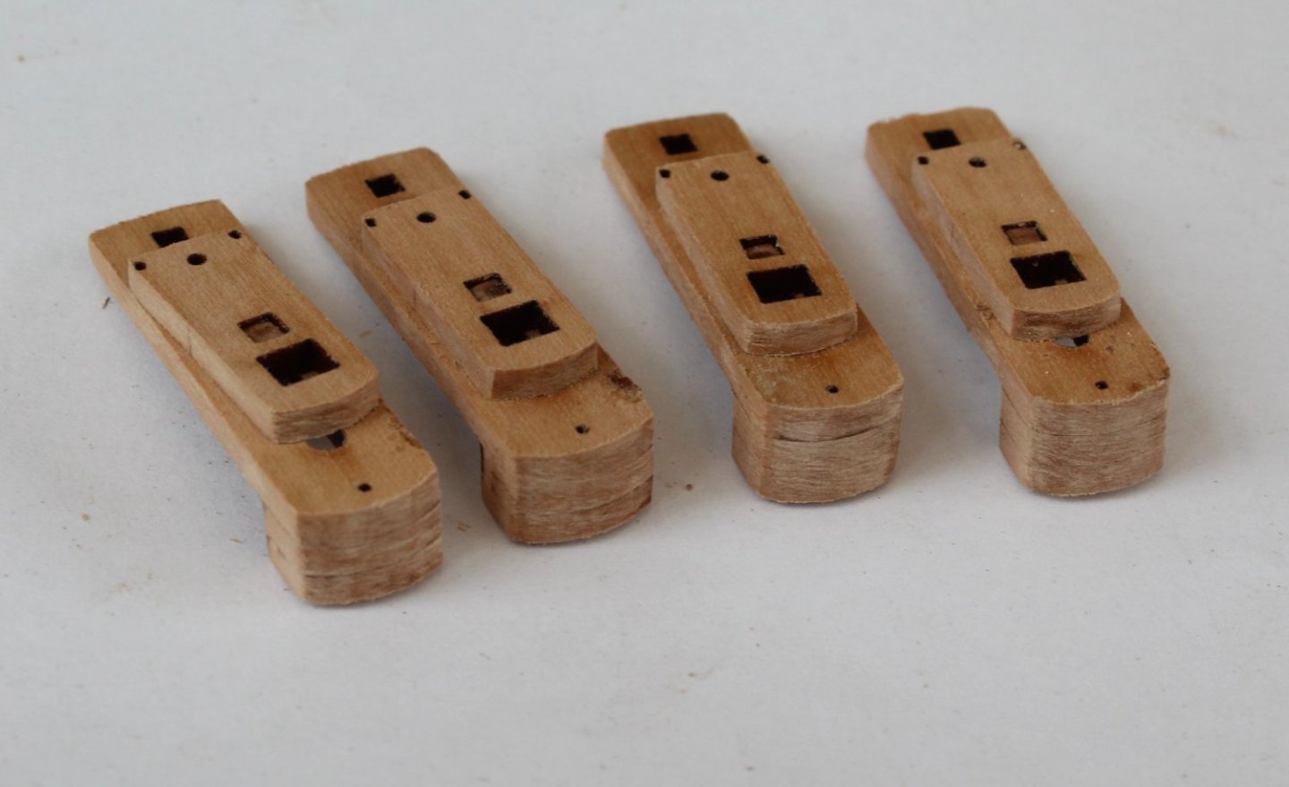
Work on the Quarter Gallery Area As much as I would have liked to replicate the quarter gallery area to the same standard as produced by Jim on his prototype build my efforts have sadly fallen someway short as the following set of photo's will demonstrate. Once the poop deck has been installed much of this area is only visible through some cut-outs thankfully. Before fitting the screens the gun ports were coated with a diluted wood filler solution and then painted red. The cabin screens require some door handles. My first check was to make sure that I could feed the handles through the holes from both sides. Once that was done the eyebolts were trimmed to sized and glued in place. I did like the natural finish of the eyebolts so decided not to paint them black. The next photo shows just how badly I finished of the screen. Although the spray mount did prevent the curling when the two screen parts were clued together I had some problems with curly during the painting phase. The screens were then added to the deck. I used the relevant poop deck beams to make sure the screens were correctly aligned. The poop deck beams are only dry fitted at this stage of the build. The captain, after a brief inspection, was not very impressed with his cabin. I fear I may be flogged as a result. There are 4 off 42-pounder carronades to build for the two cabin areas. There is a t-piece which allows the the carronade carriage to slide over the top of the carronade skead. In the build manual the top of the t-piece , when fitted, is shown to be proud of the carriage. This is only possible if the bottom of the t-piece (yellow arrow) is rotated through 90 degrees so it fits in the slot but would be an incorrect assembly. The top of the t-piece, when correctly fitted, actually sits flush with the top of the carriage (blue arrow). The basic assembly of the carronades is complete, noting the carriage is only dry fitted as the parts need to be painted flat red before the assembly phase.


- 587 replies
-
- 10
-
-
- Indefatigable
- Vanguard Models
- (and 1 more)
-
Thanks Jack. I learn more from my mistakes so I do like to highlight both my successes and failures.
- 160 replies
-
- 1
-
-
- Alert
- vanguard models
- (and 1 more)
-
Thanks, I agree. I can't wait to see the end result when the cabin work is complete. The use of the Spray Mount is a game changer with regards to gluing thin patterns back to back without the dreaded curl.
- 587 replies
-
- 2
-
-
- Indefatigable
- Vanguard Models
- (and 1 more)
-
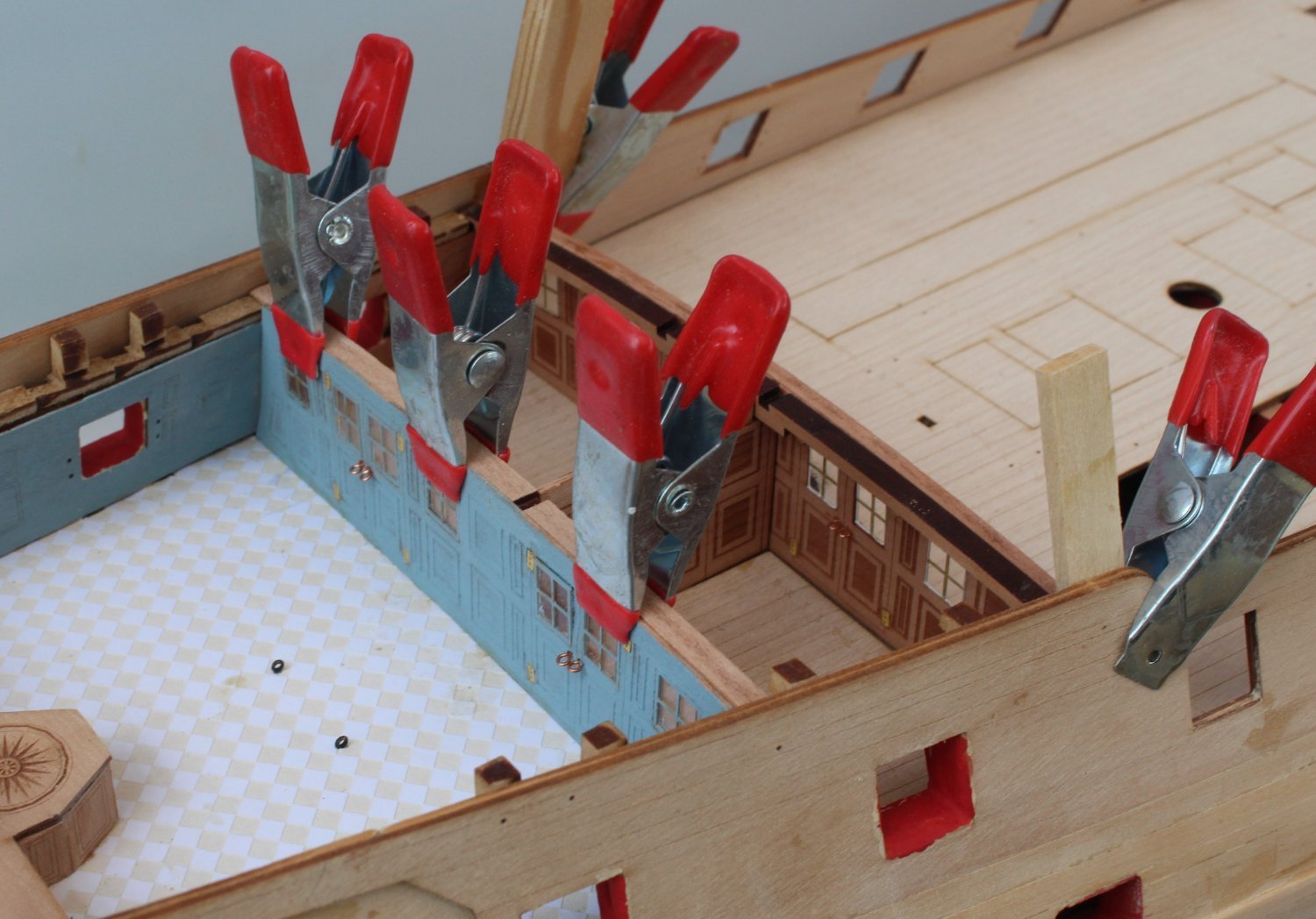
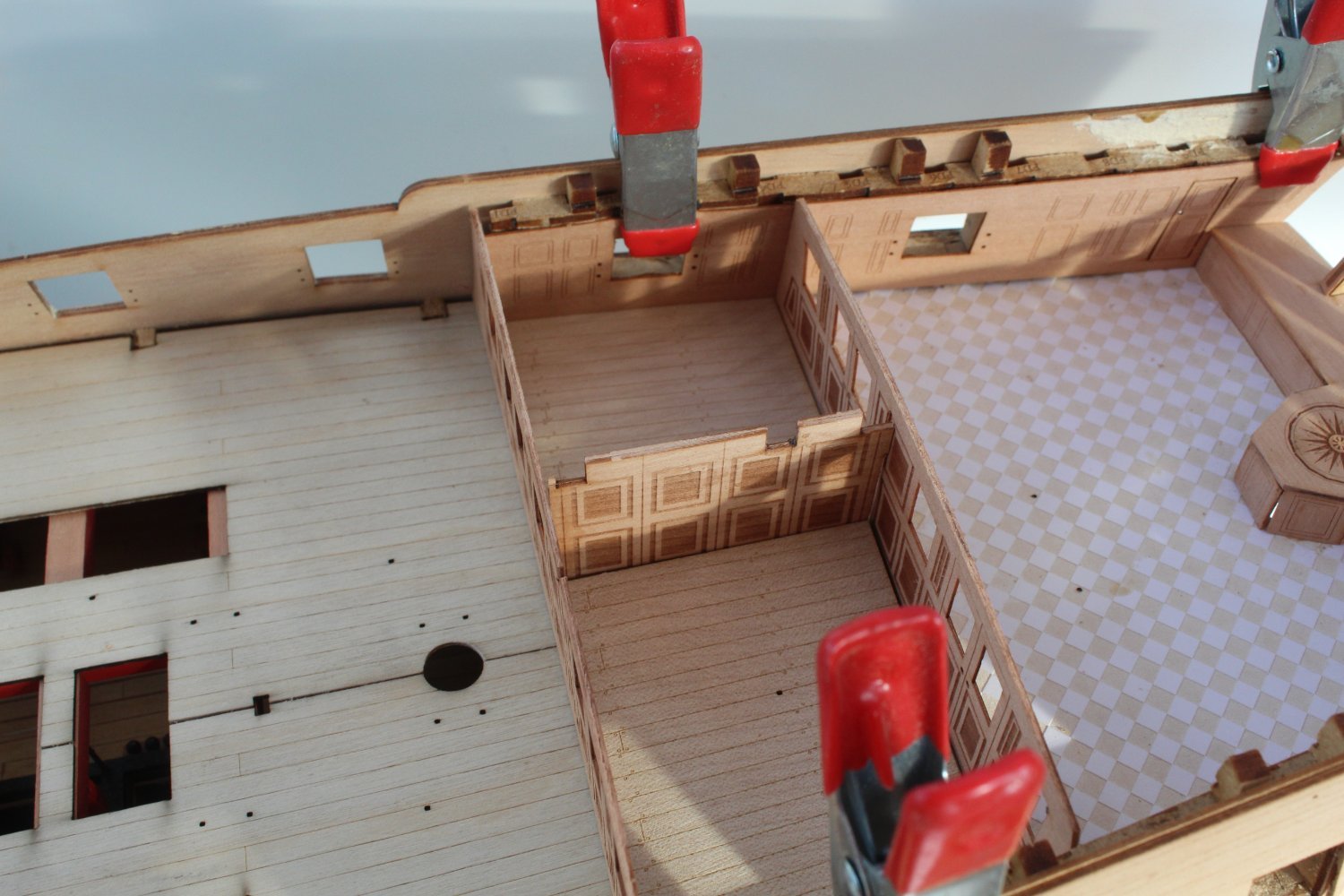
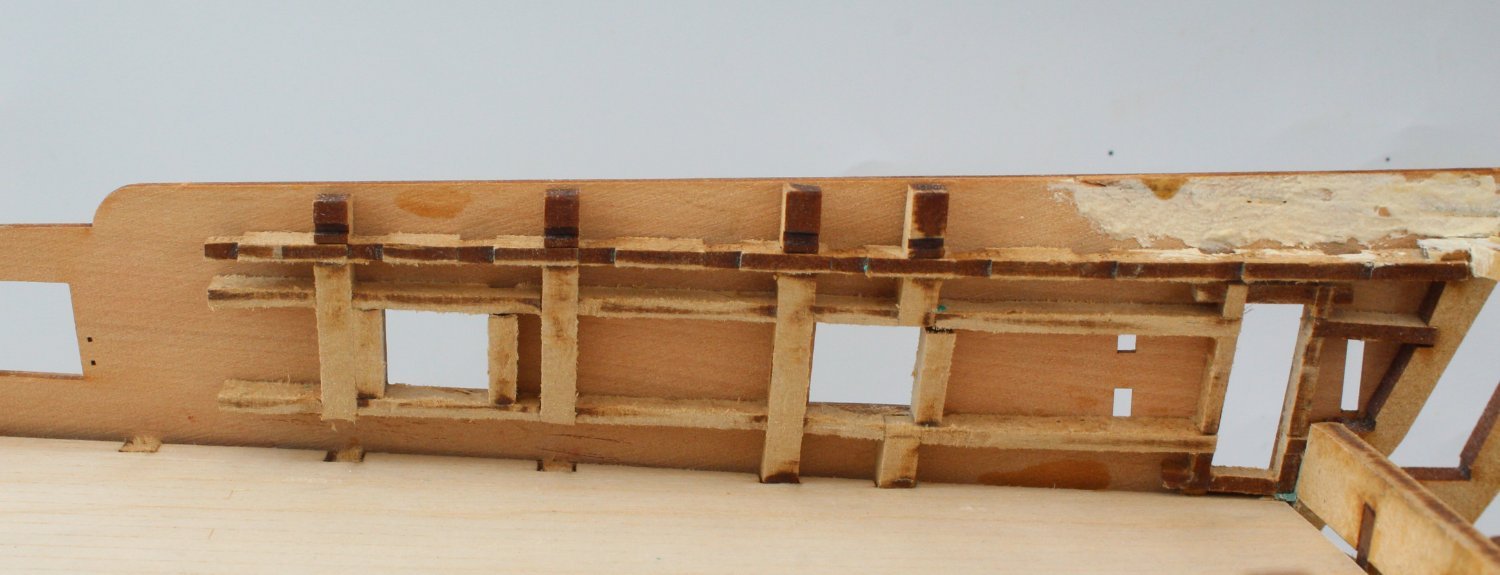
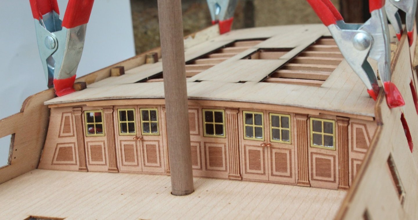
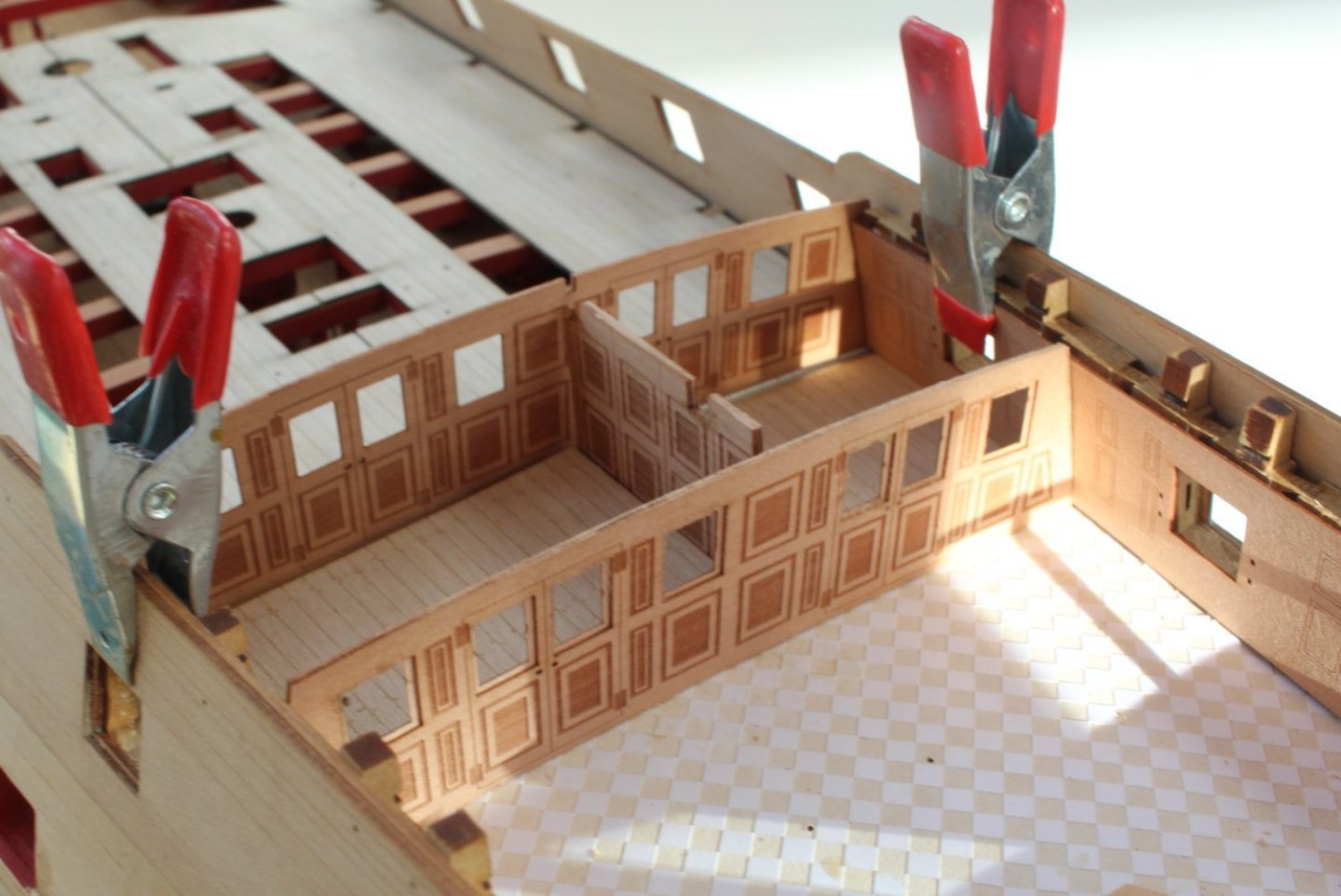
Cabin Screens Using the spray mount adhesive the three cabin screen parts were glued together without any curling. With the quarter gallery inner bulwarks clamped in place the basic cabin screens were test fitted along with the two pear deck sections which sit either side of the middle screen. Everything seems to fit together. In the first photo I did place the forward most screen the wrong way round. The forward screen has now been turned around. The quarter gallery bulwark test fit. The second cabin area with deck parts test fitted. More work is required to complete the screen assemblies such as adding window frames, Columns, painting, etc. The quarter gallery bulwarks also needs to be painted. I have received some oil paints today so the quarter gallery furniture (table and chairs) can be painted.


- 587 replies
-
- 11
-
-
- Indefatigable
- Vanguard Models
- (and 1 more)
-
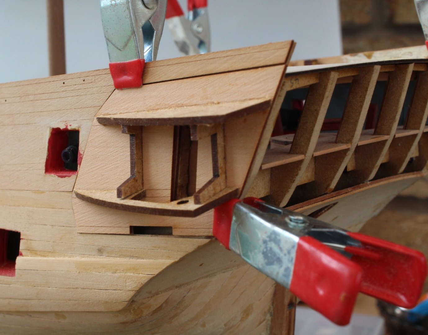
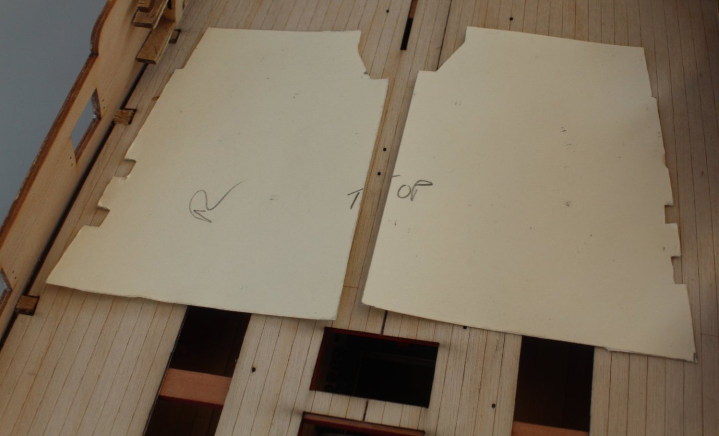
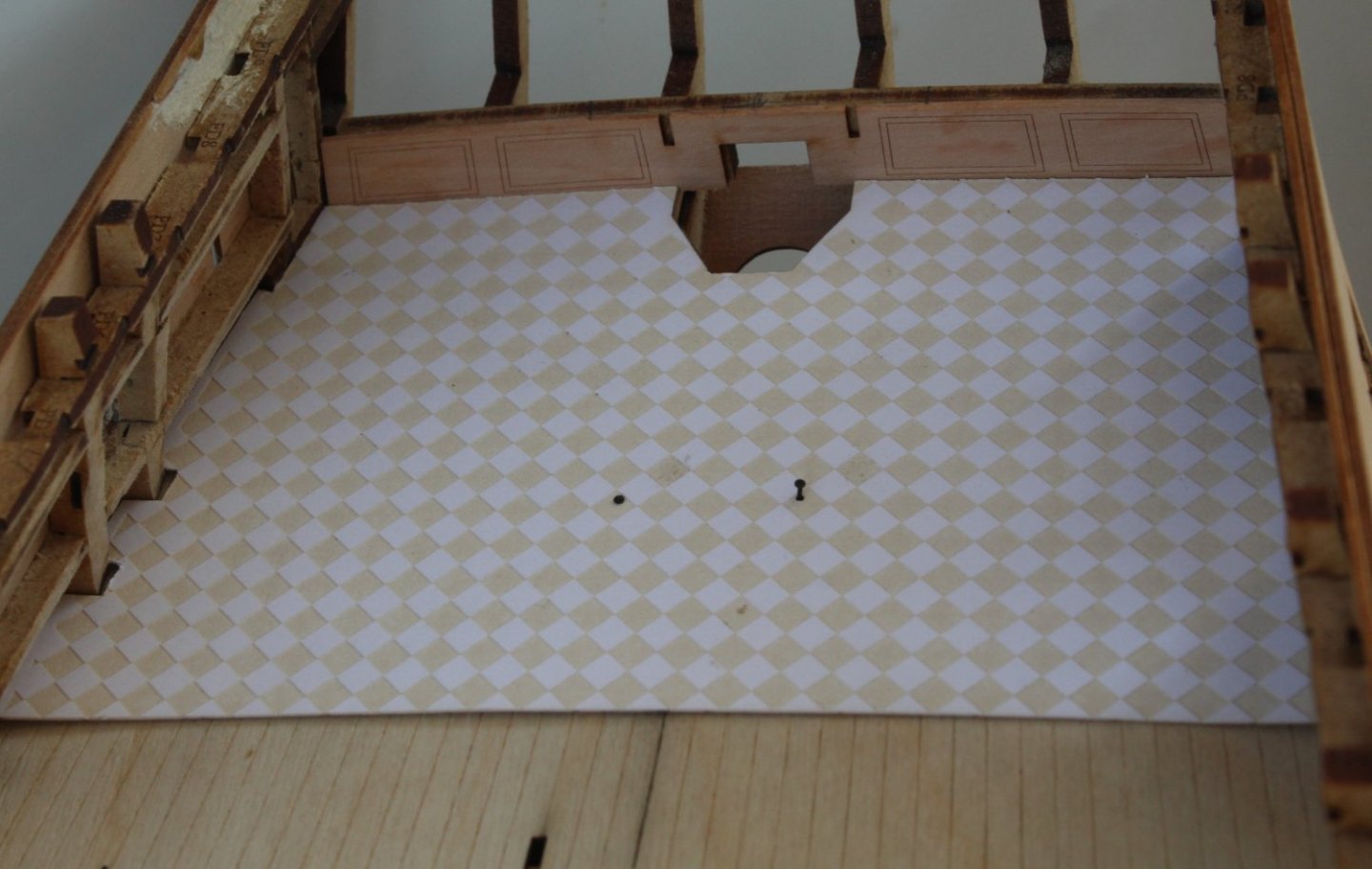
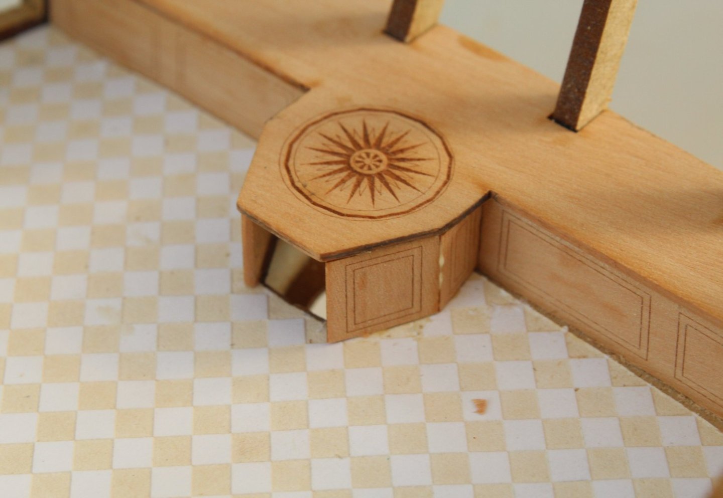
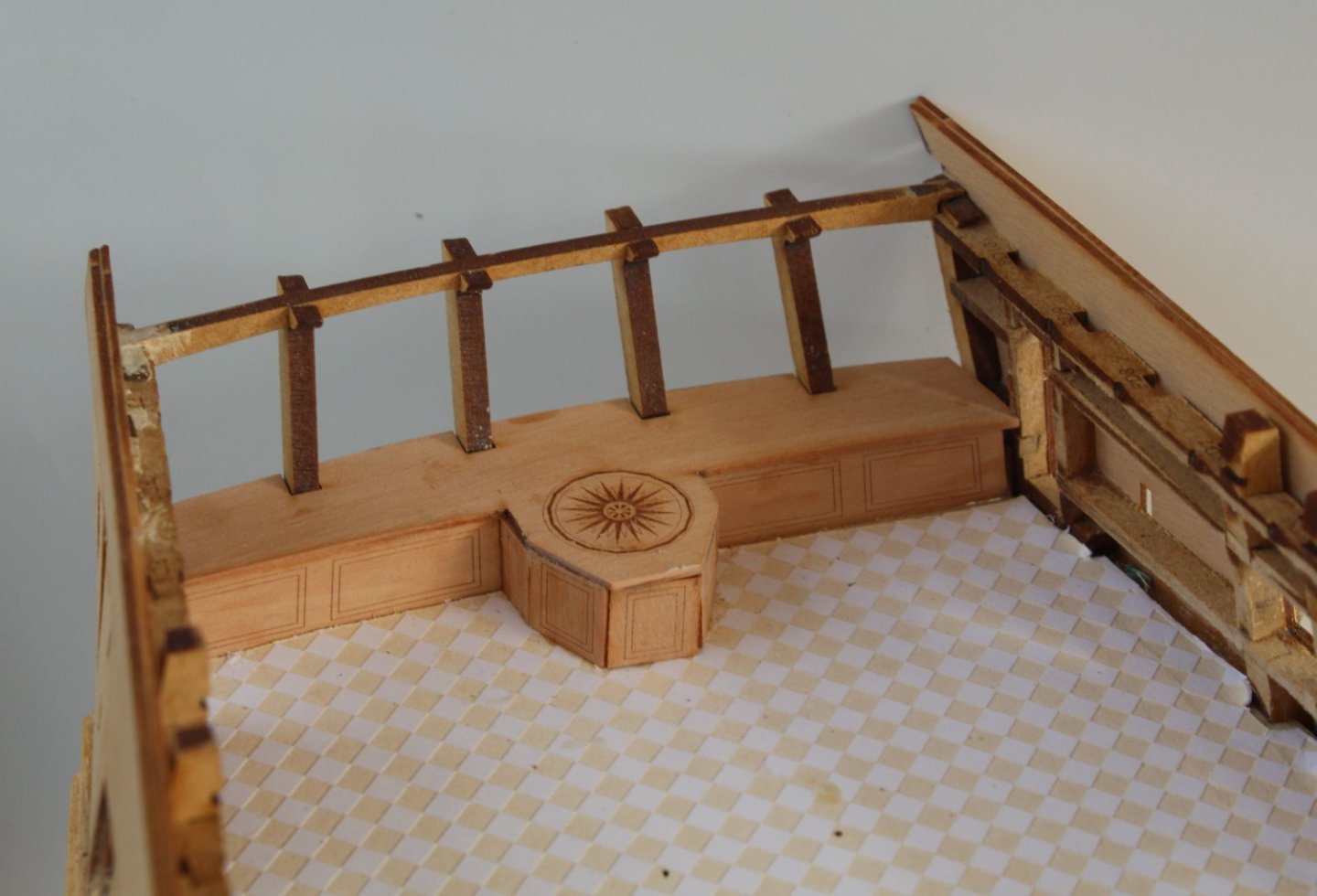
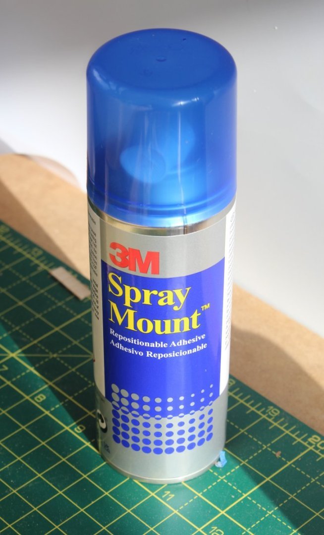
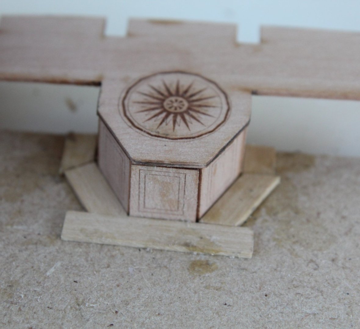
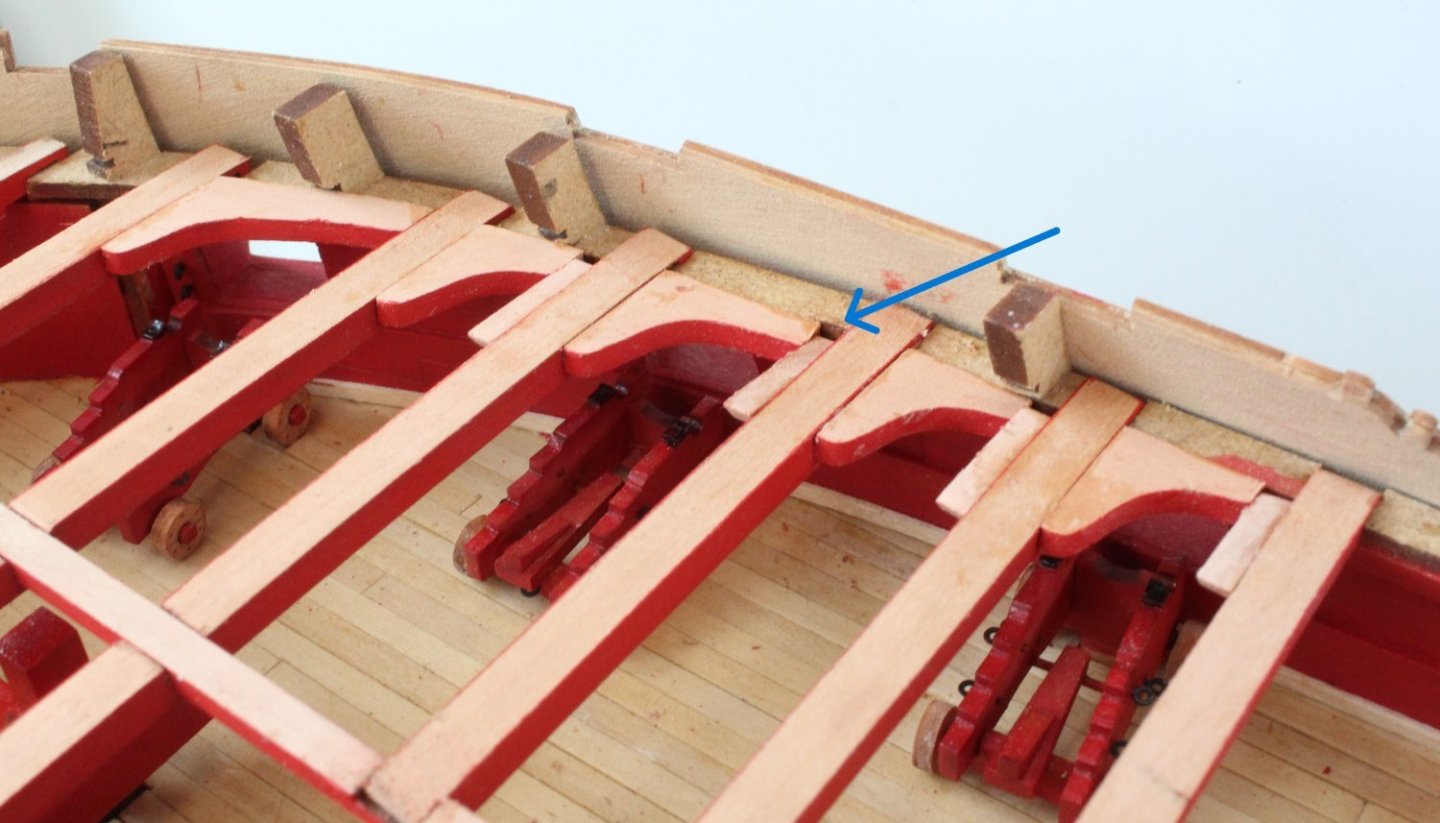
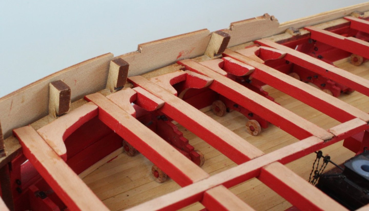
Rudder Housing and Quarter Gallery Deck With the stern cabin rear bulkhead glued in place it was time to fit the Quarter Gallery Deck. The kit supplied deck does require a little bit of trimming. I opted to make a left and right half carboard template which were cut to the required dimensions. With the cardboard template placed on top of the quarter gallery deck I was able to trim it to the right size. A trial fit shows it is aligned and two pins drop nicely into the holes beneath the deck. Next the rudder housing was assembled. I started with the left and right back pieces and used the top pattern to check the position. The next two pieces were then added. Once again the top panel was used to check the alignment. The final end piece was glued in place along with the top panel. It is not my best work as you can seer that the left hand side panel is a bit askew where it joins the central end panel. However when the poop deck is installed, it will be difficult to see this housing so I am content with the outcome. Next up will be the assembly of the various cabin screens. I have bought some spray mount for this task which should prevent the warping of the parts which normally happens when pva is used.
- 587 replies
-
- 9
-
-
- Indefatigable
- Vanguard Models
- (and 1 more)
-
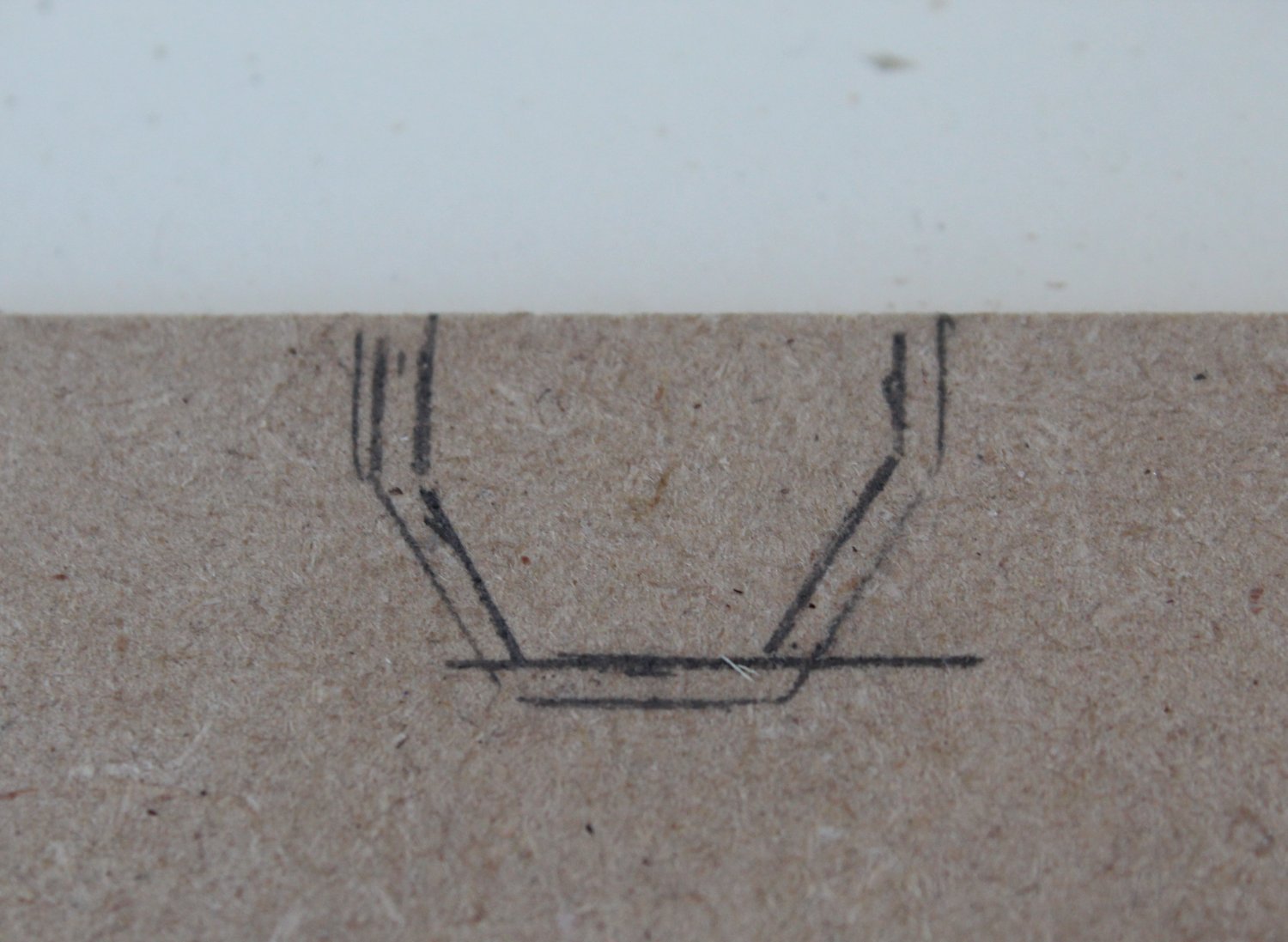
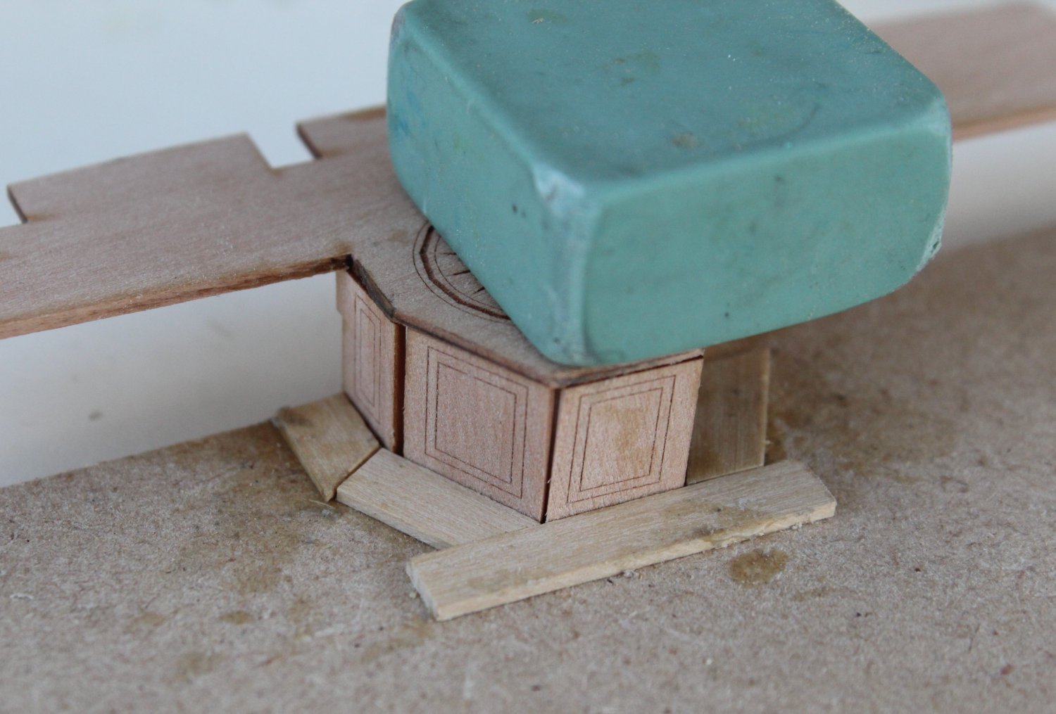
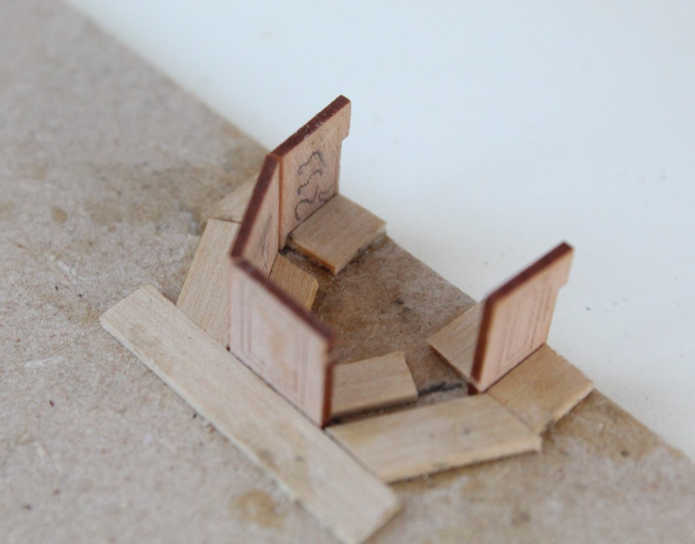
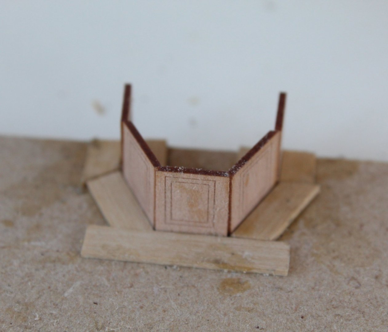
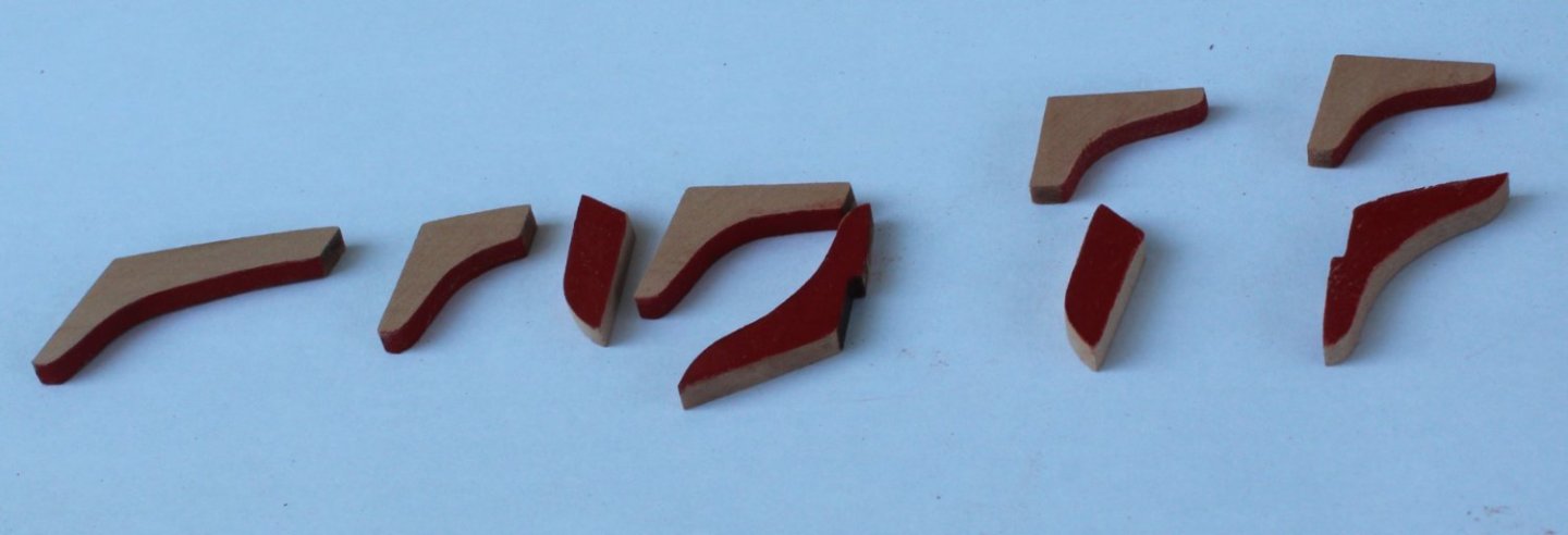
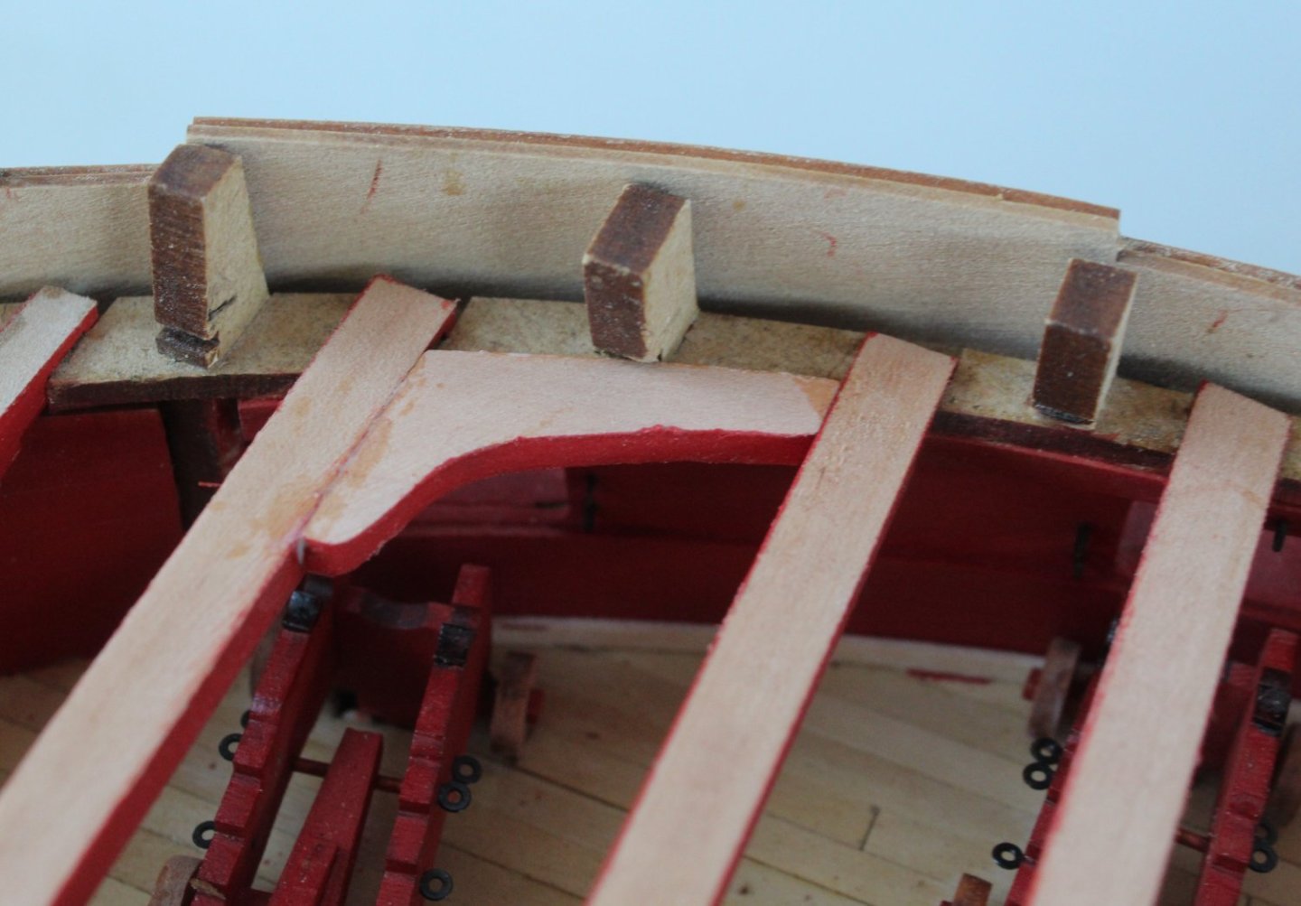
Rudder Housing Jig The assembly of the rudder housing comprises 6 parts. Each of the 5 side parts requires bevelling of the edges to get the required shaping of the rudder housing. As I think this could be a tricky little assembly to get right I decided I should make a simple jig to assist with the bevelling. I thought this small side project might be of interest to some of the Indy builders. Step 1 - Mark out the required pattern Using a scrap bit of MDF I used the top rudder housing pattern to draw the required outer edge shape. Once that was done I was able to add the inner edges. Step 2 - Making the Jig Using some spare planking material I glued support pieces to either side of the guide lines. I started with adding the support pieces to the outer edges and used the top pattern to double check the were correctly positioned. Once I was happy with the outer supports I cut and glued the inner support pieces. This time I used the side patters to ensure the correct gap was set. Step 3 - Bevelling the edges The bevelling of the edges was a relatively simple task. As each part was bevelled it was tested in the jig. I used to the top part to double check the alignment. Fingers crossed this means when it time to fit the parts to the quarter gallery deck there should not be any problems.

- 587 replies
-
- 9
-
-
- Indefatigable
- Vanguard Models
- (and 1 more)
-
Many thanks, I am taking more time than normal for me to check things before I glue things.
- 587 replies
-
- 3
-
-
- Indefatigable
- Vanguard Models
- (and 1 more)
-
I use the other build logs as a guide in conjunction with the manual and plan sheets. I would strongly recommend that you test fit the hanging knees with the deck beams before the deck beams are glued in place. So much easier to see what mods, if any, are required to the knees.
- 587 replies
-
- 3
-
-
- Indefatigable
- Vanguard Models
- (and 1 more)
-
Thanks, I have already started to make a simple jig to help with the alignment and fitting, using the top shelf as a guide
- 587 replies
-
- 1
-
-
- Indefatigable
- Vanguard Models
- (and 1 more)
-
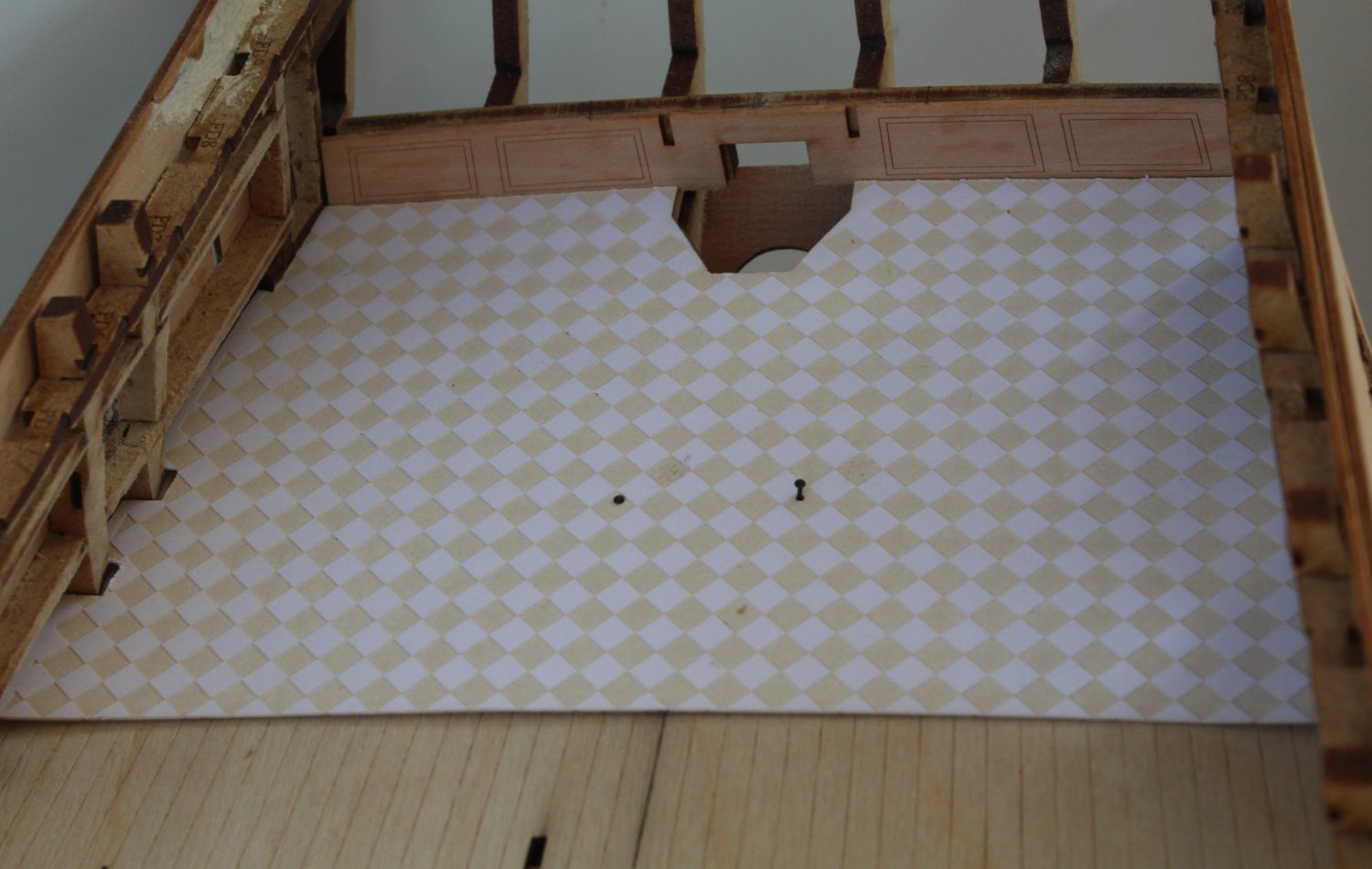
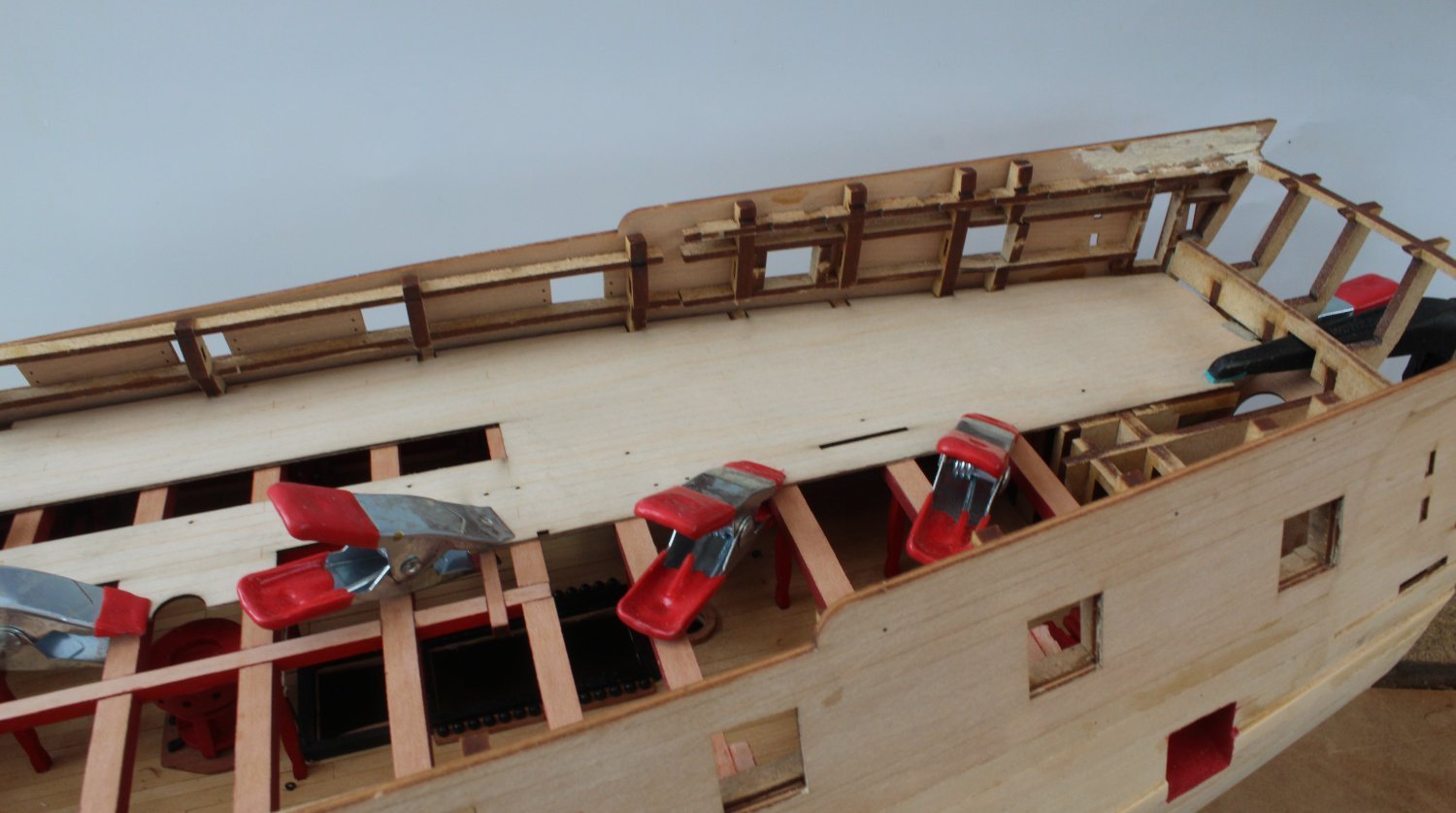
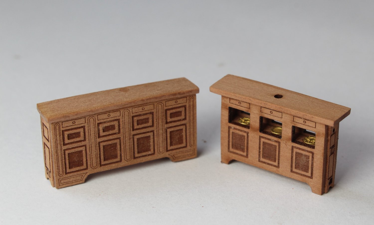
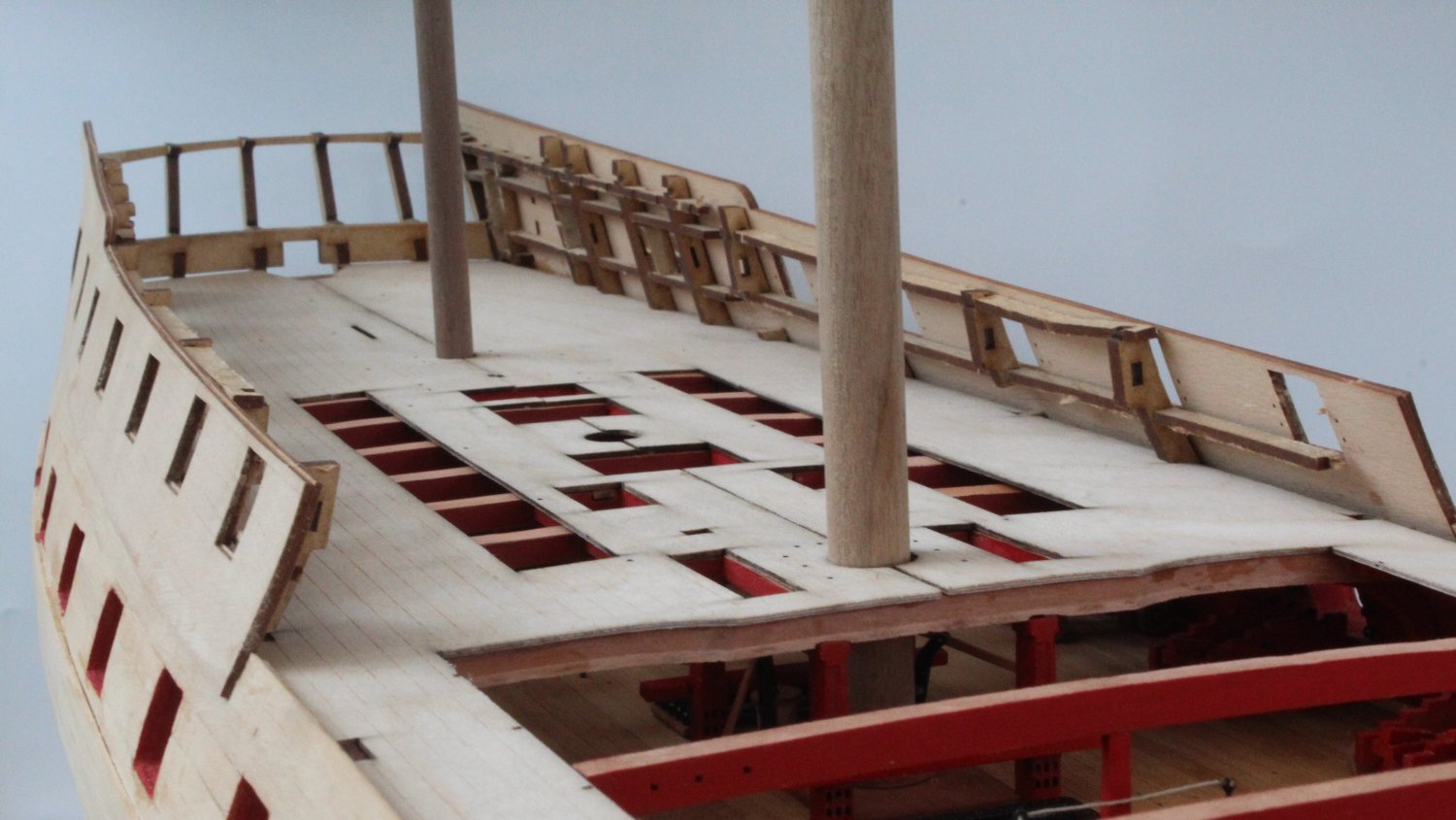
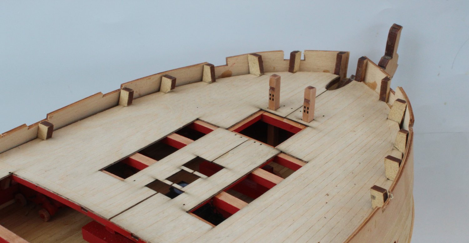
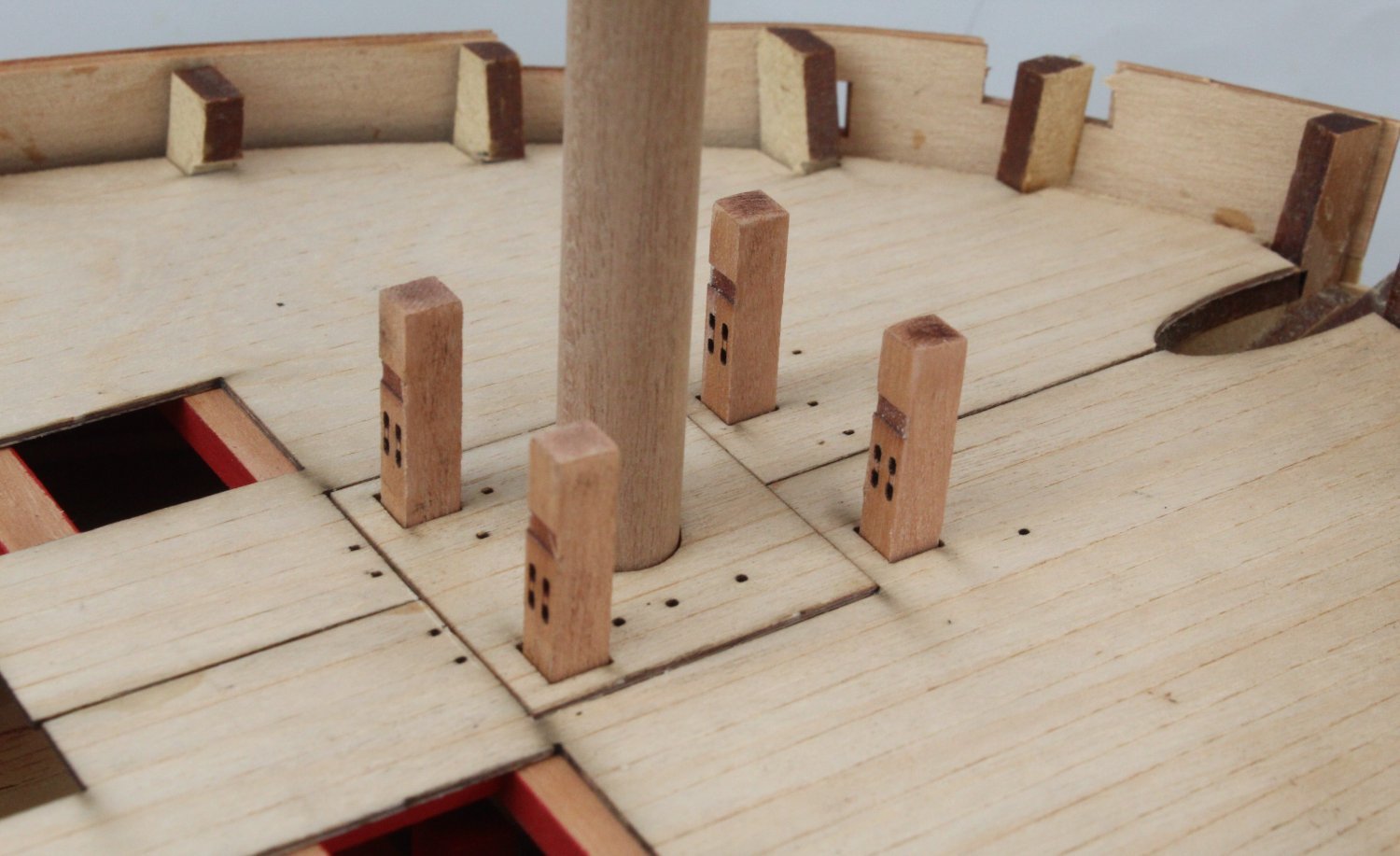
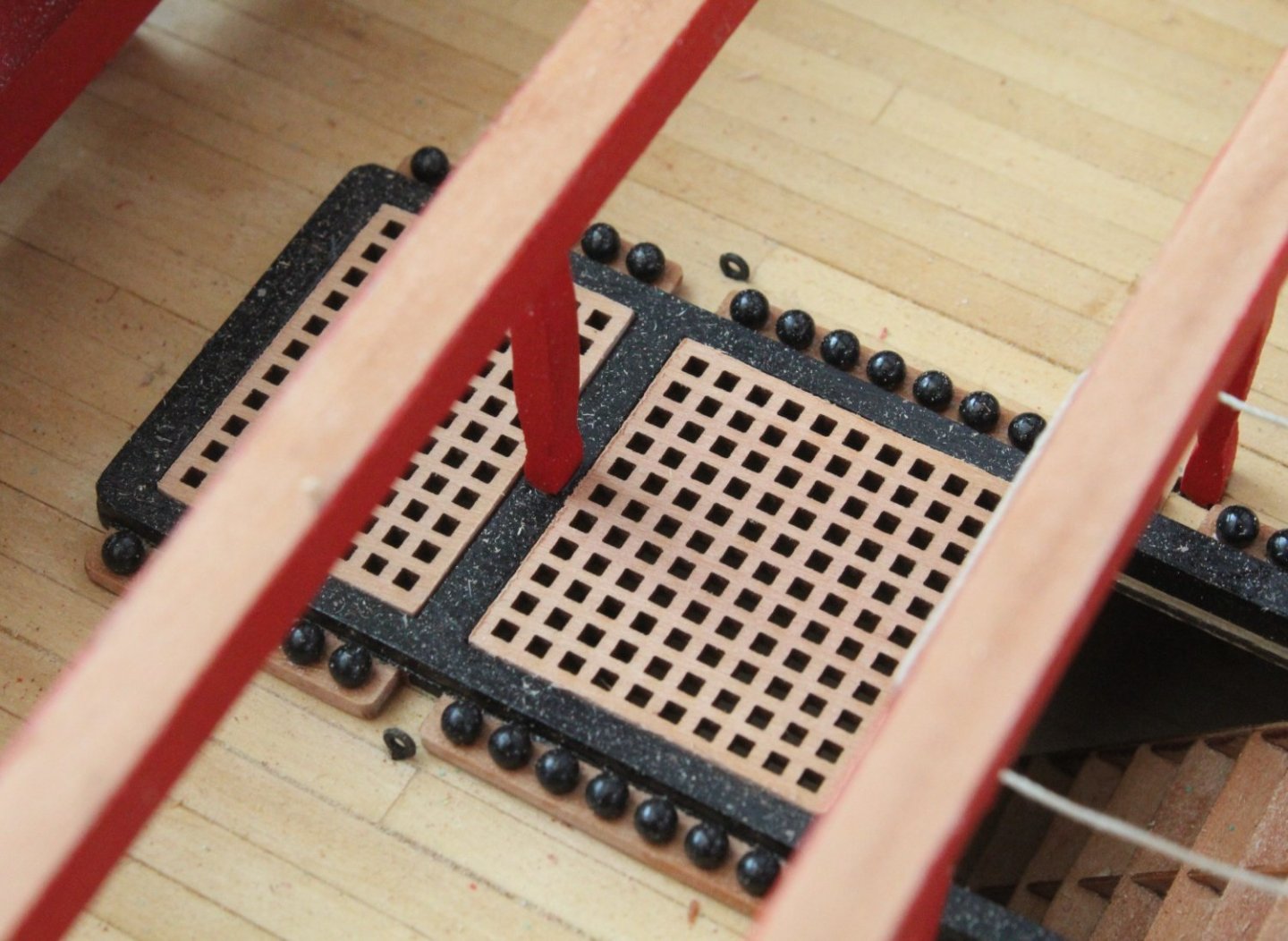
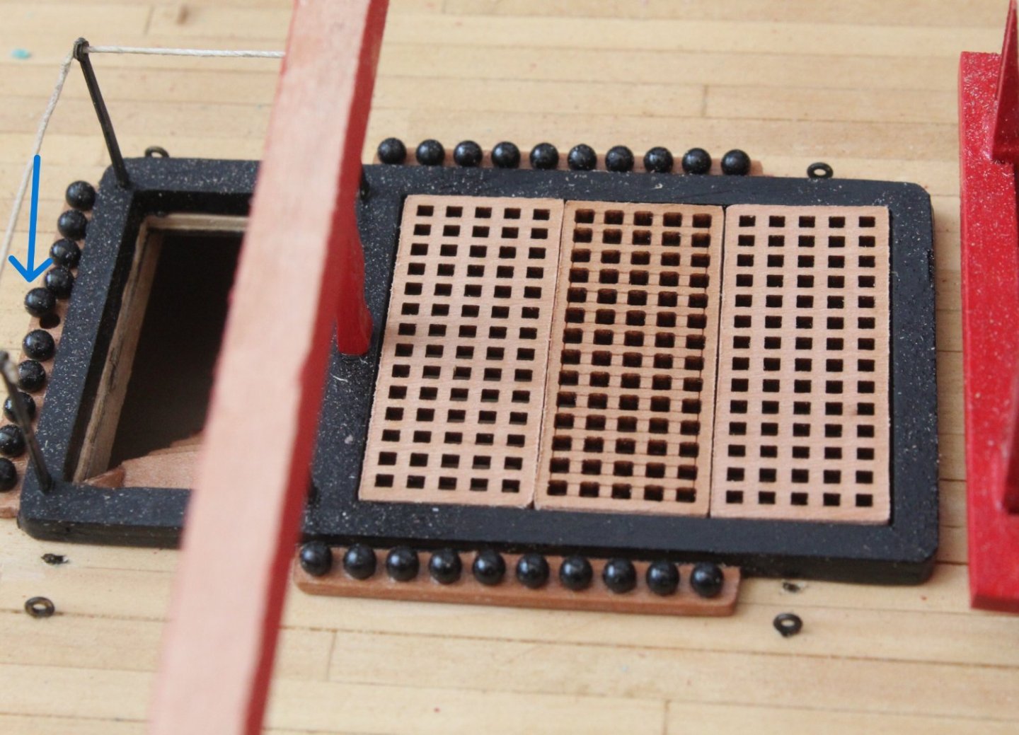
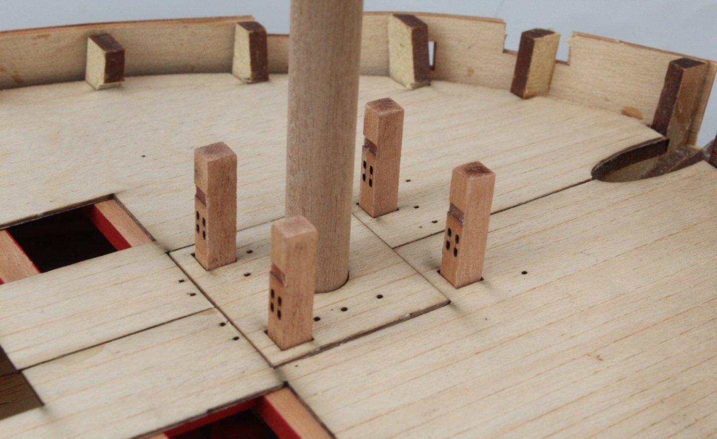
Gun Deck Hatches I realised that I had not fitted the coamings to the gun deck hatches. This has now been rectified. When looking at the next photo I noticed one of cannon balls is trying to escape. I did consider the suggestion made by Jim of splitting the deck patterns in to three parts, but decided to try gluing the first (right hand side) as one complete piece. Using plenty of the clamps the deck pattern was glued in place. Whilst waiting for glue to dry I decided build a couple of deck items. I think they turned out OK. After another trial fit of the left hand deck pattern I decided to fit as one complete piece. There was plenty of clamps used as the glue was left to cure. A couple of hours later the clamps were removed and the masts and bitts were test fitted. Everything was perfectly aligned. The scrap framework was then successfully removed and the remaining bulkhead ear remnants were sanded flat to the deck level. The remaining bulwarks were then sanded smooth. To finish of todays work a test fit of the stern cabin rear bulkhead was undertaken. I also started to look at the assembly of the rudder casing and concluded that this is going to be a tricky little item to build.


- 587 replies
-
- 10
-
-
- Indefatigable
- Vanguard Models
- (and 1 more)
-
Thats a great idea Jim, it did not occur to me to do that. Many thanks
- 587 replies
-
- 1
-
-
- Indefatigable
- Vanguard Models
- (and 1 more)
-
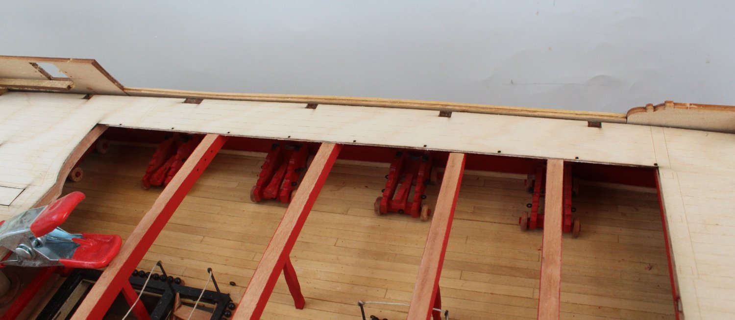
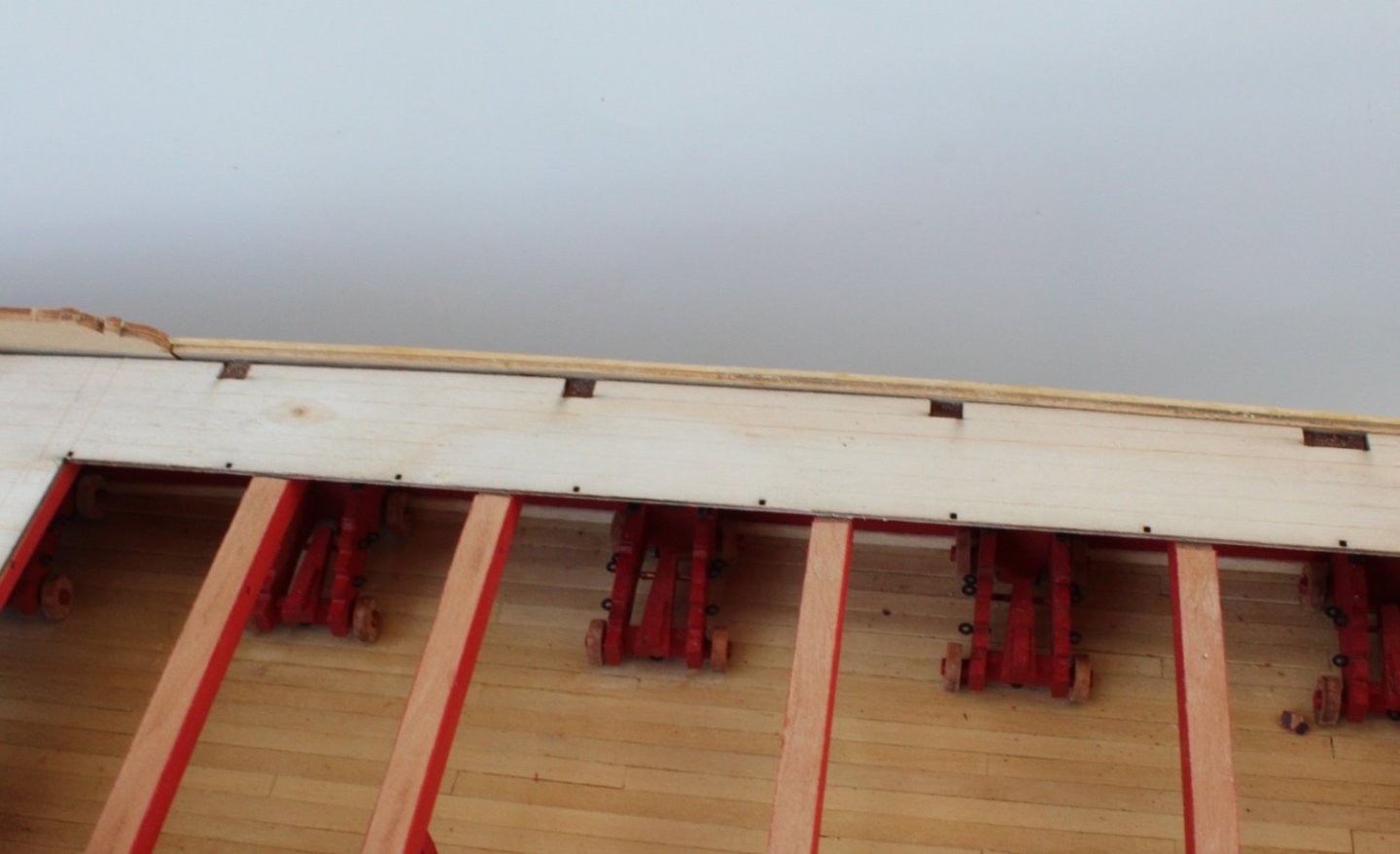
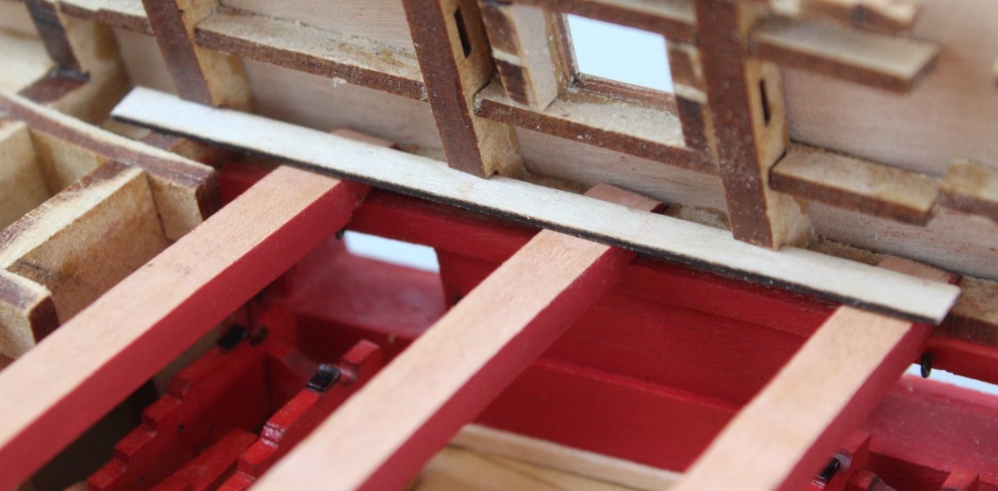
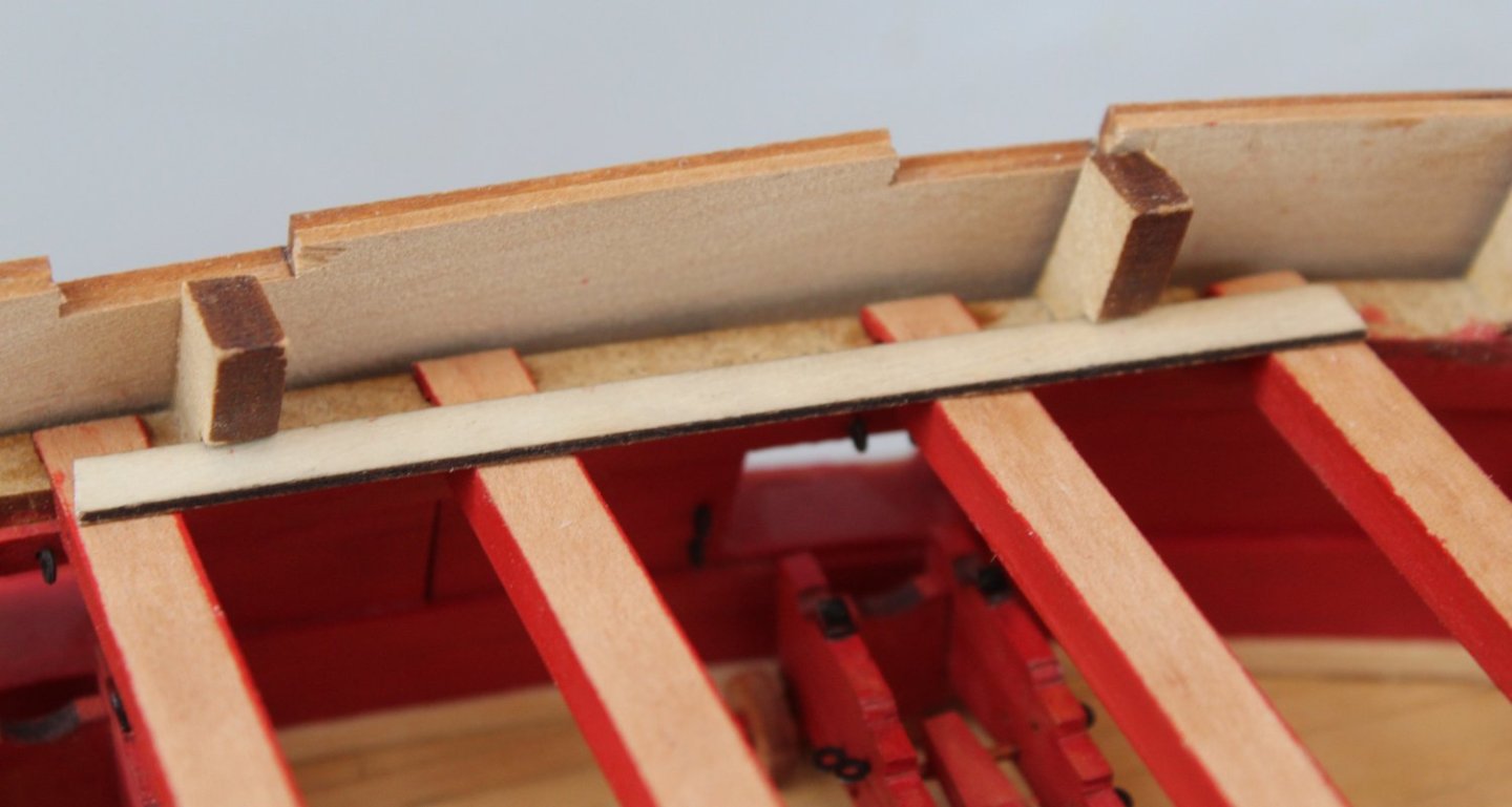
Upper Deck Trial Fitting - Left Hand Side As with the right hand side I did have to trim a bit of back edge in order to line up the upper deck pattern with the bulkhead ears. After cleaning the laser char from the edges a trial fit was undertaken. As can be seen in the first photo below the quarterdeck section is a perfect fit. The gangway section also was a great fit, with the pattern sitting in the slots provided. However the forecastle section requires a bit more work as the pattern will sit flush with the right hand pattern. The alignment problem was due to pattern not locating fully in to one of the bulkhead ear slots. After a little bit of sanding of the slot opening the deck pattern was refitted and this time it became fully engaged. It will require a little bit more fettling to ensure the central sections of both patterns are aligned.


- 587 replies
-
- 12
-
-
- Indefatigable
- Vanguard Models
- (and 1 more)
-
Thanks Chris, nice to know it not my back workmanship.
- 587 replies
-
- 3
-
-
- Indefatigable
- Vanguard Models
- (and 1 more)
-
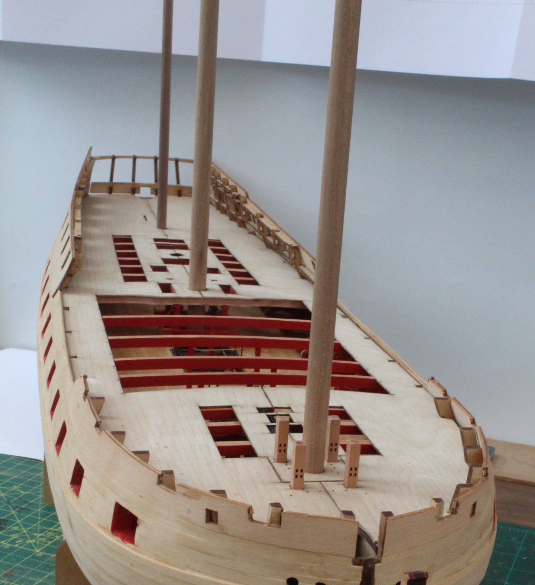
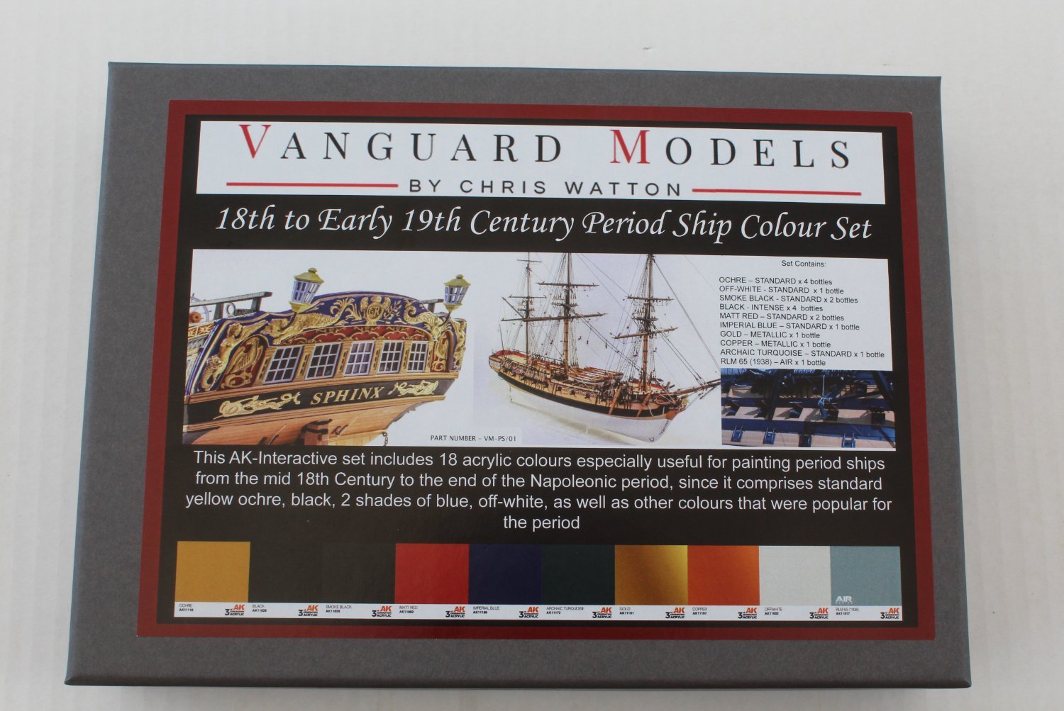
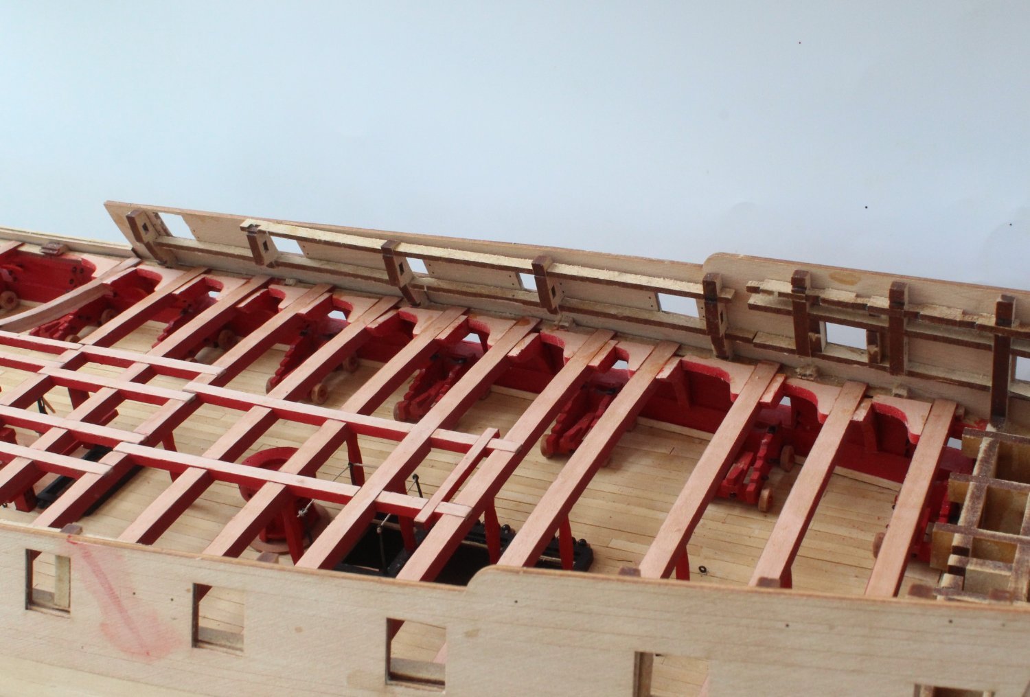
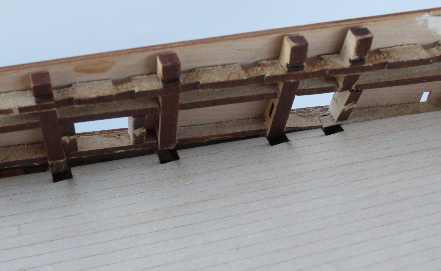
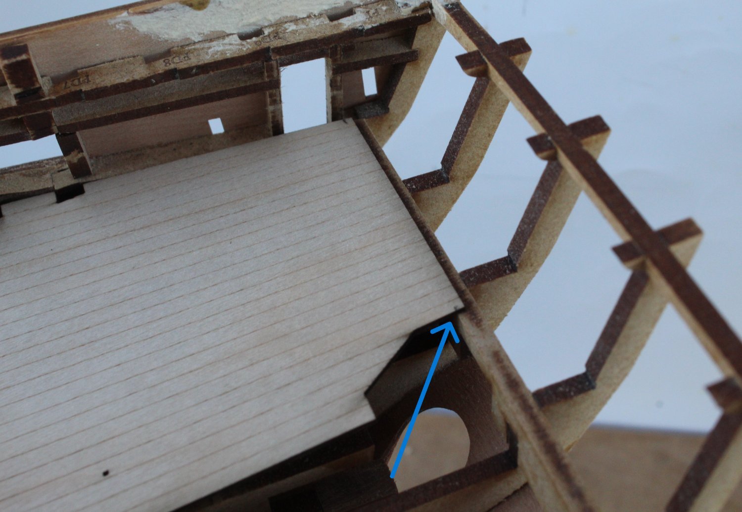
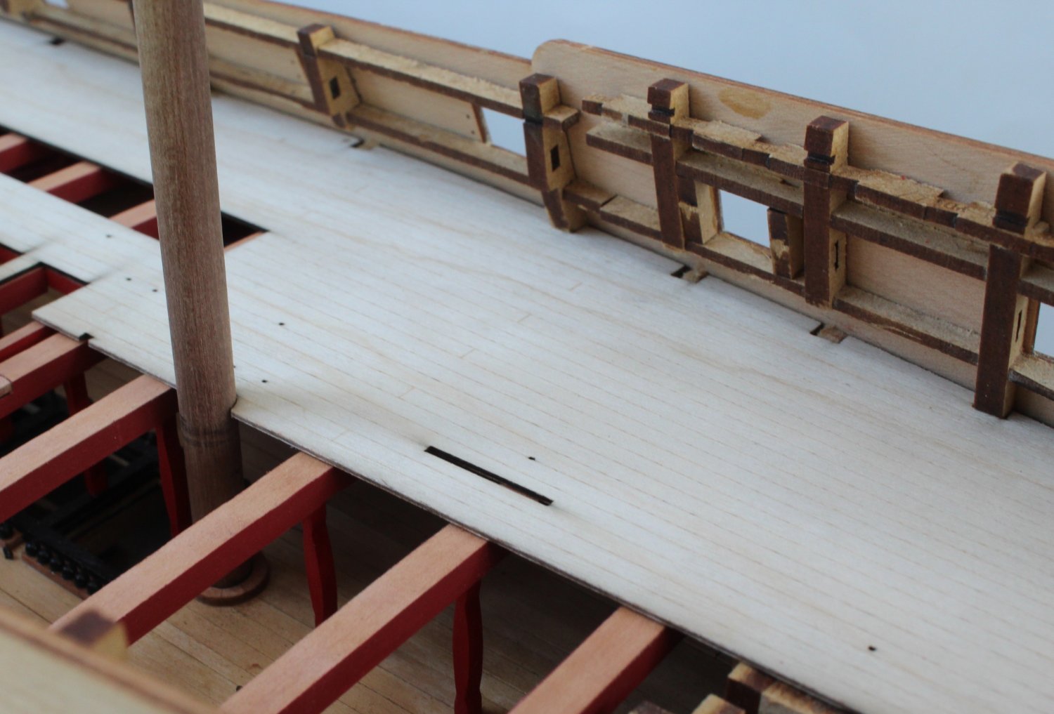
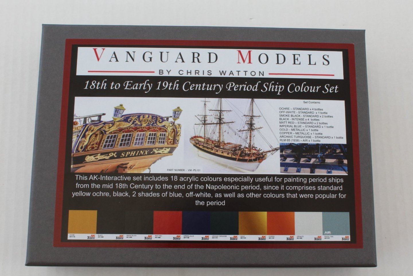
Paint Set I treated myself to a set of paints in readiness for the next phase of the Indy build. Quarterdeck Hanging and Lodging Knees After painting the various quarterdeck knee parts I spent a couple of hours this morning fitting them to the Indy. I did have to shape all the hanging knees before fitting. As I indicating in my previous post it would have been much easier to check the fit of the hanging knees prior to gluing the deck beams in place and to then fit them as each deck beam was added. Considering these items will be very difficult to see I was not too worry about my shoddy workmanship. Upper Deck Pattern - Right Hand Side The upper deck base pattern comprises a right hand and left hand base pattern. Each base pattern includes the quarterdeck, gangway and forecastle decks. Starting with the right hand side pattern I removed the laser char from the edges, checked and cleaned the locating slots on the bulkhead ears. The pattern was then lined up with the bulkhead ears. On first glance everything looks good but on closer inspection the deck does require a trim at the stern end, as indicated by the blue arrow. Once the deck was trimmed the upper deck (right-hand side) was test fitted. It seems to be a good fit and the holes for both the mizzen and main masts are perfectly aligned with the gundeck holes below. The gangway section sits nicely in the slots on the deck beams. The forecastle bitt pattern is also perfectly aligned with the lower deck locating slot. My fairing of the upper section of the forecastle bulkheads could have been better however, as can be seen by the yellow arrow. This gapping will be hidden once the ears have been removed and the inner bulwark patterns and forecastle deck planking have been added. I now have to repeat the process with the left hand pattern. Once I am happy with how it fits I will glue both parts in place.


- 587 replies
-
- 7
-
-
- Indefatigable
- Vanguard Models
- (and 1 more)
-
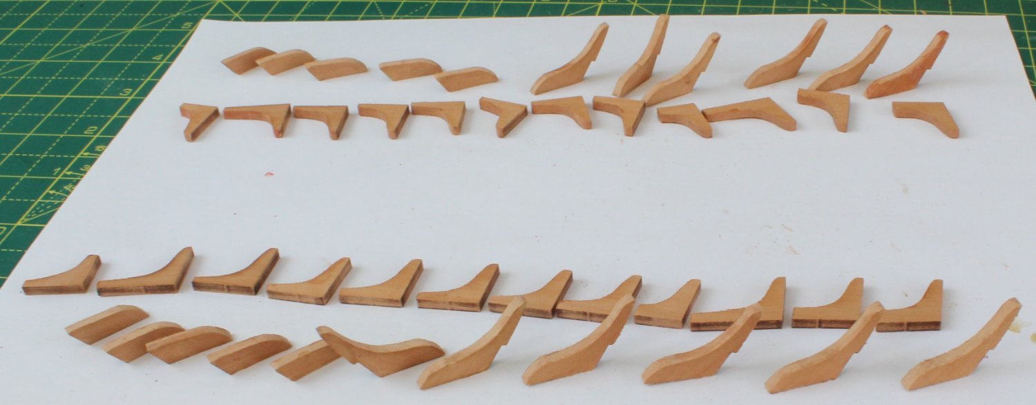
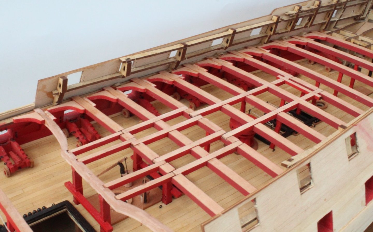
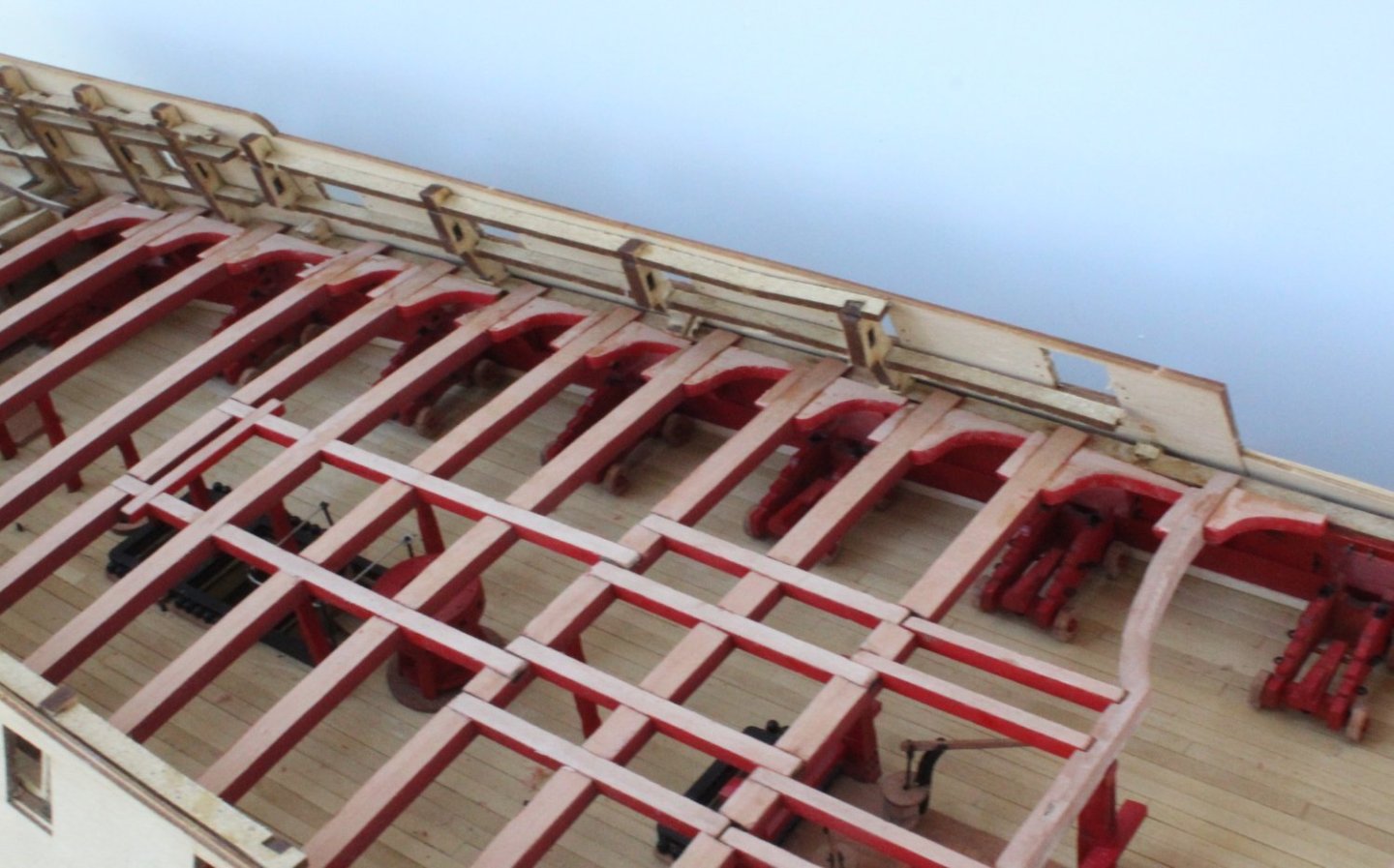
Hanging and Lodging Knees There is quite a bit of work required to prepare and fit the hanging and lodging knees. These are option parts to fit as, once the upper decks have been fitted, they will difficult to see. In retrospect I wish I had taken time to check and modify the various hanging knees before the deck beams were glued in place as I think it would have made the task easier. I started with the forecastle area. Once the laser char had been removed, varnish was applied to the areas to be painted. A couple coats of flat red was then brushed on once the varnish had dried. It was then a case a fitting the various knees, noting I did have to trim / shape the hanging knees. As can be seen below I did not make a great job of all the knees. Given the deck will be sat on top I am not too bother by this. There are three knees per side to be fitted to the boat beams. I opted to only fit the middle one (blue arrow) as the others were a bit close to some cleats (yellow arrows) and I was a bit concerned that it may hinder the rigging. Moving on to the quarterdeck area the knees have had the laser char removed and varnish has been applied to the painted areas. These will now need a little bit of time to allow the varnish to dry before they can be painted and fitted.


- 587 replies
-
- 8
-
-
- Indefatigable
- Vanguard Models
- (and 1 more)
-
A great decision. My Indy planking is no where near up to your standard but I'm very tempted to just varnish the boxwood hull but paint black and yellow above the waterline.
- 648 replies
-
- 2
-
-
- Indefatigable
- Vanguard Models
- (and 1 more)
-
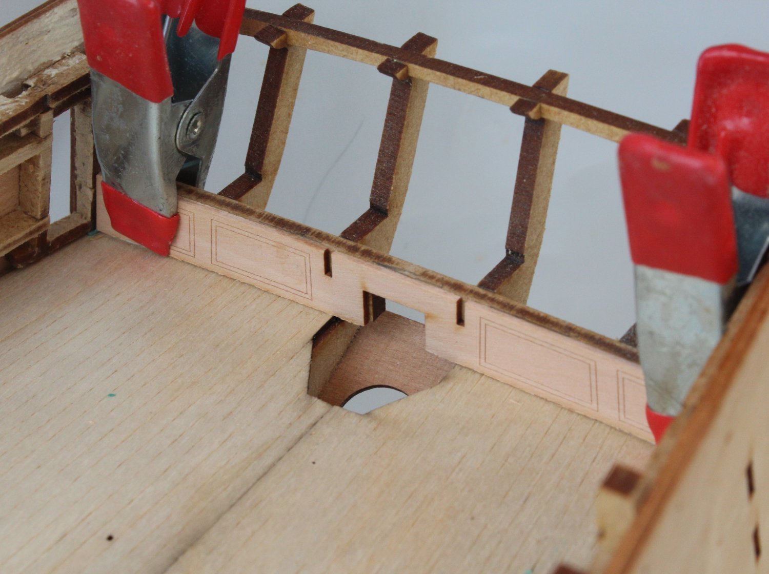
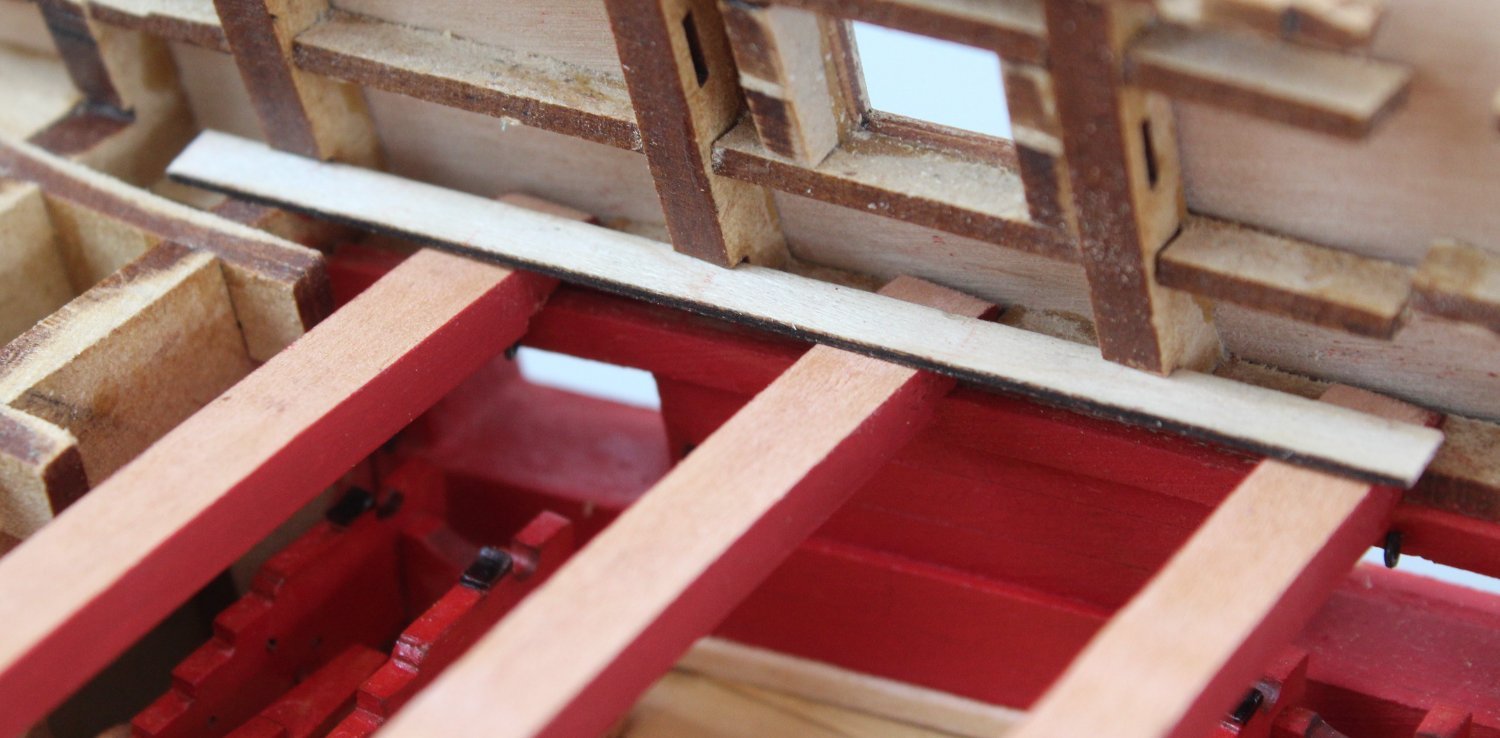
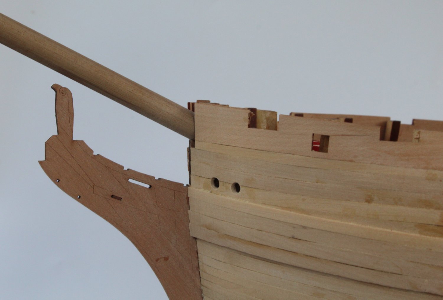
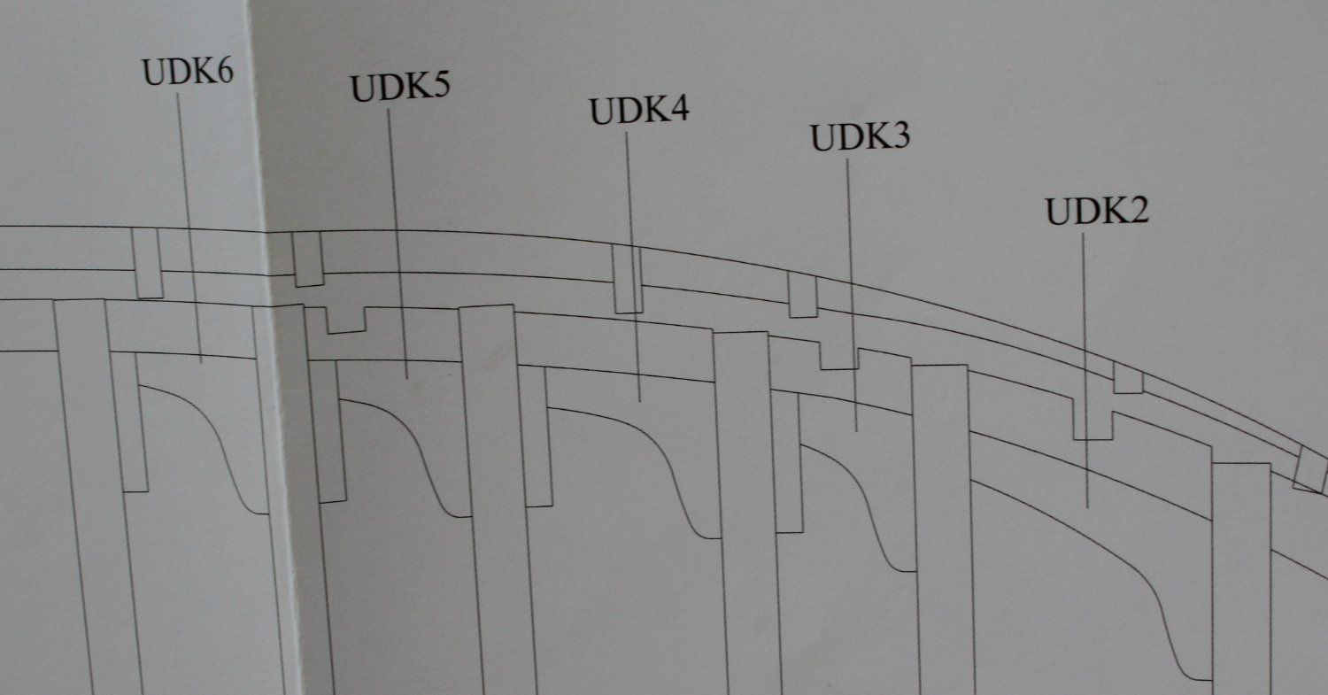
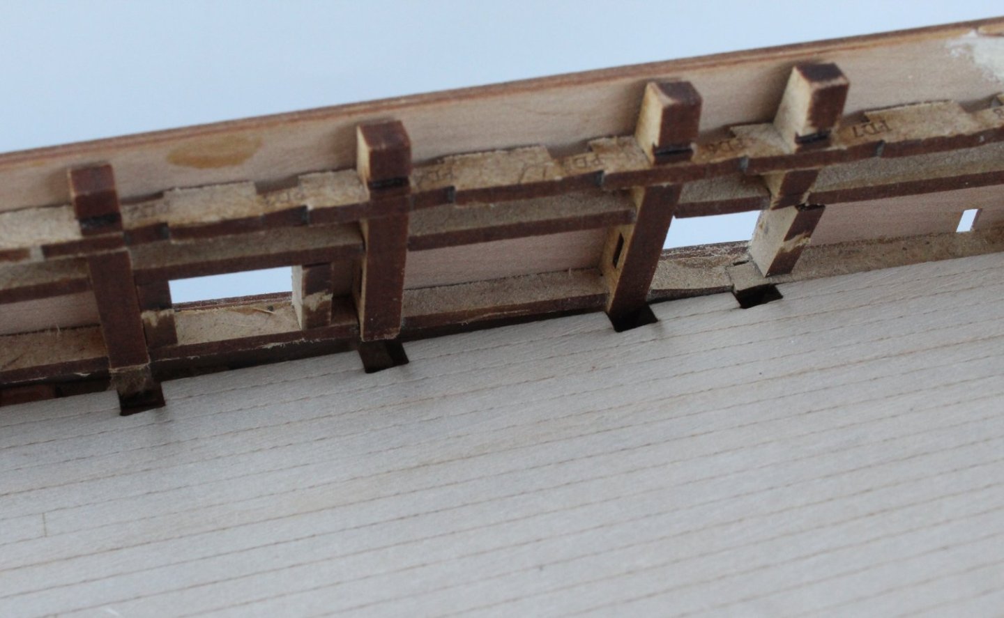
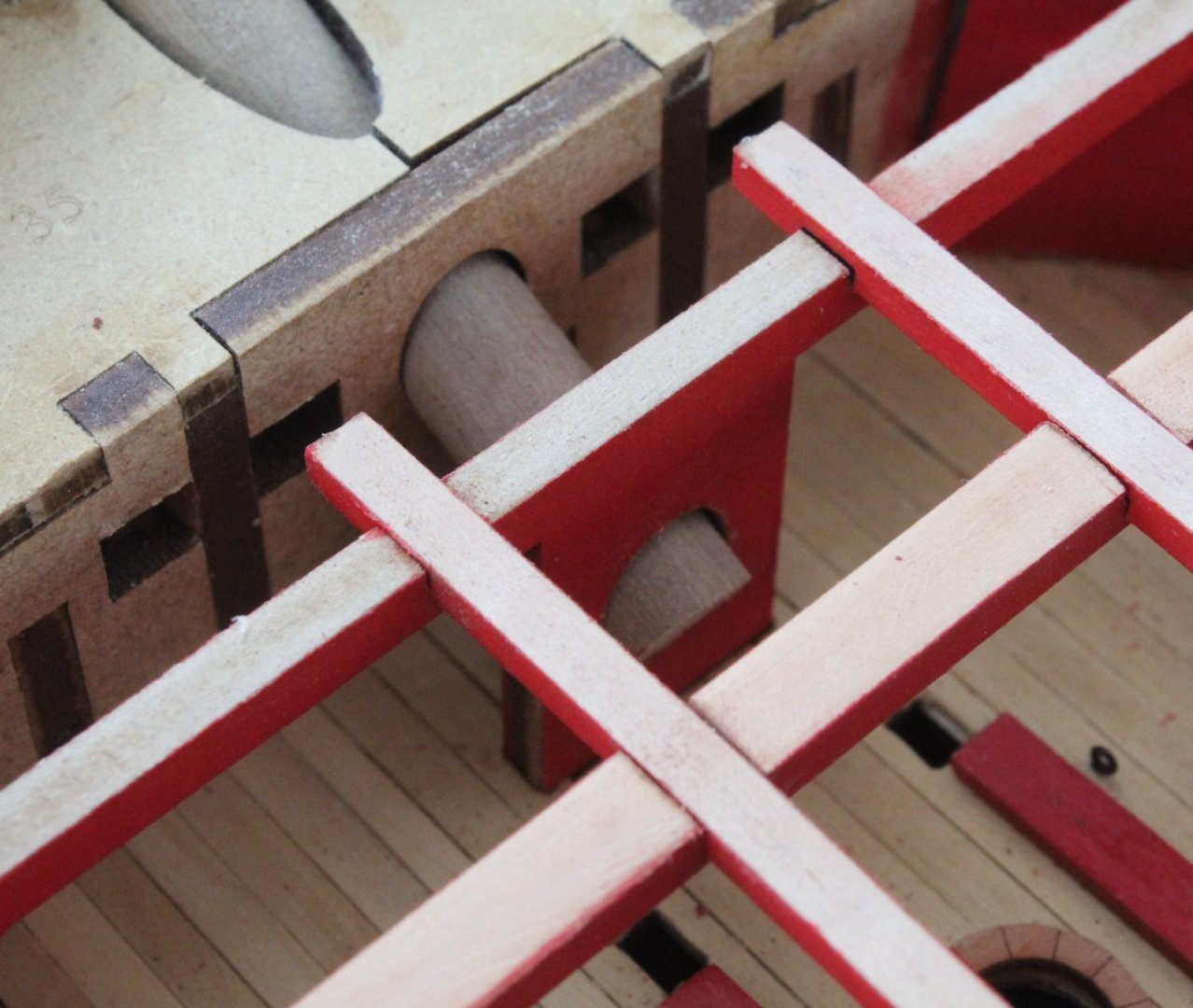
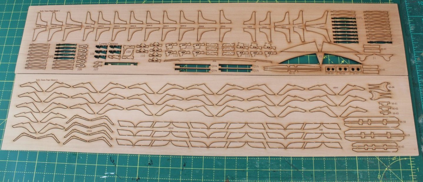
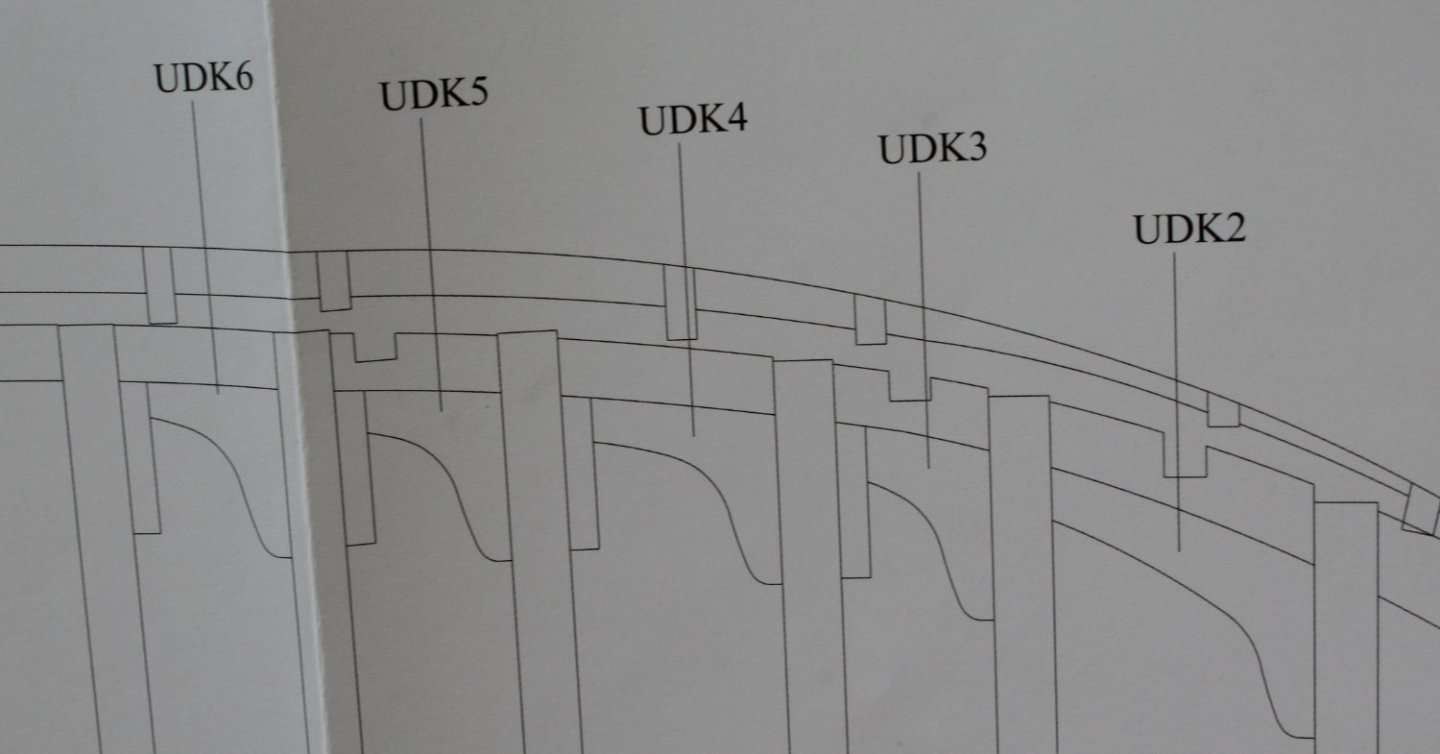
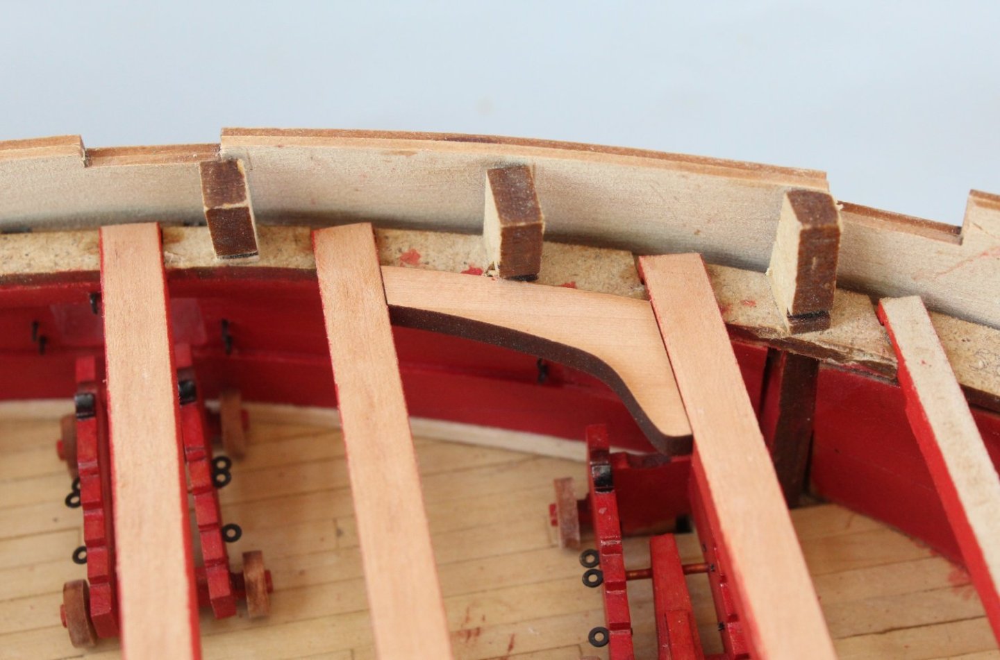
Bowsprit Test Fit Before gluing the forecastle deck beam in place I did a trial fit of the bowsprit. I thought it would be easier to modify the elongated hole in the UD01 deck beam off the hull, if required. Fortunately the 10mm dowel slotted in without any issues so I was able to glue the deck beams in place. Checking Deck Pattern Slots The bulkhead ears have slots which will be used to help locate the upper deck pattern(s) in the correct place. With the deck beams in situ I thought it would be sensible to check the slots, using a scrap bit of material. Apart from one slot on the forecastle end everything looked good. I had not noticed that one end of the deck beam (UD03) was not fully engaged in the locating slots on the left hand side. I have been able to make a fix to resolve this issue in readiness for fitting the deck pattern. Lodging Knees Turning my attention to the lodging and hanging Knees I have the relevant plan sheet hanging up on the wall for reference and the two pear wood sheets with all the various knees on my workbench, Starting at the bow end the various lodging knees are indicated on the plan sheet, as shown below. The hanging knees are also indicated on the plan sheet on the other side of the hull (not shown in the photo below) An initial test fit of the first lodging knee looks good. Laser char removal and painting required before it can be glued in place.

- 587 replies
-
- 4
-
-
- Indefatigable
- Vanguard Models
- (and 1 more)
-
Thank you Chris. I really like the look of the painted deck beams.
- 587 replies
-
- 2
-
-
- Indefatigable
- Vanguard Models
- (and 1 more)