Glenn-UK
-
Posts
3,175 -
Joined
-
Last visited
Content Type
Profiles
Forums
Gallery
Events
Everything posted by Glenn-UK
-
 Jim used wood glue on the prototype and then pinned the 2nd planks in place. The pin holes were then filled during the sanding phase before painting.
- 233 replies
-
- 1
-

-
- Indefatigable
- Vanguard Models
- (and 1 more)
-
Fabulous. I'm very impatient to restart my Indy but I must wait to allow time for my back to recover.
- 443 replies
-
- 5
-
-
- Indefatigable
- Vanguard Models
- (and 1 more)
-
Nice progress. With regards to the waterline I tend to use the plan sheets to work out the position at the bow and stern. When practical to do so I will also add some additional reference points in between. I will add a length of tape using the reference points as a guide. I will adjust the tape as necessary to get a nice smooth flow in conjunction with the waterline tool. I find getting the aft portion (transom area) of the waterline most troublesome to get right.
- 59 replies
-
- 2
-
-
- Alert
- Vanguard Models
- (and 1 more)
-
Nicely done, great job. I'm still AWOL with my glass back so not sure when I can resume work on my Indy. My current goal is be be in a fit state to travel to a Switzerland (by train) at start of July. Plan is for a river cruise to Dussledorf. If back is still playing up I might try to book into one of the special Swiss clinics for instant and total pain relief
- 233 replies
-
- 2
-
-

-
- Indefatigable
- Vanguard Models
- (and 1 more)
-
No idea why that happen I have deleted and readded the picture and seems OK now
- 426 replies
-
- 2
-
-
- Vanguard Models
- Sphinx
- (and 1 more)
-
I would recommend lateral plank bending for the bow area. I tapered the bow planks to approx 3mm
- 233 replies
-
- 2
-
-
- Indefatigable
- Vanguard Models
- (and 1 more)
-
Recovery is still very slow so I must limit my shipyard time at the moment.
- 233 replies
-
- 3
-
-

-
- Indefatigable
- Vanguard Models
- (and 1 more)
-
Looking good you'll soon be overtaking me on my Indy build
- 233 replies
-
- 1
-
-
- Indefatigable
- Vanguard Models
- (and 1 more)
-
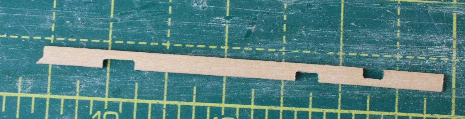
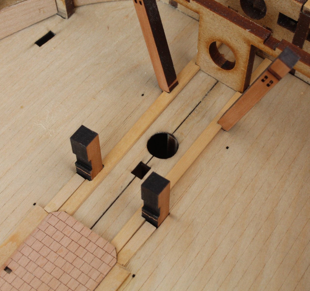
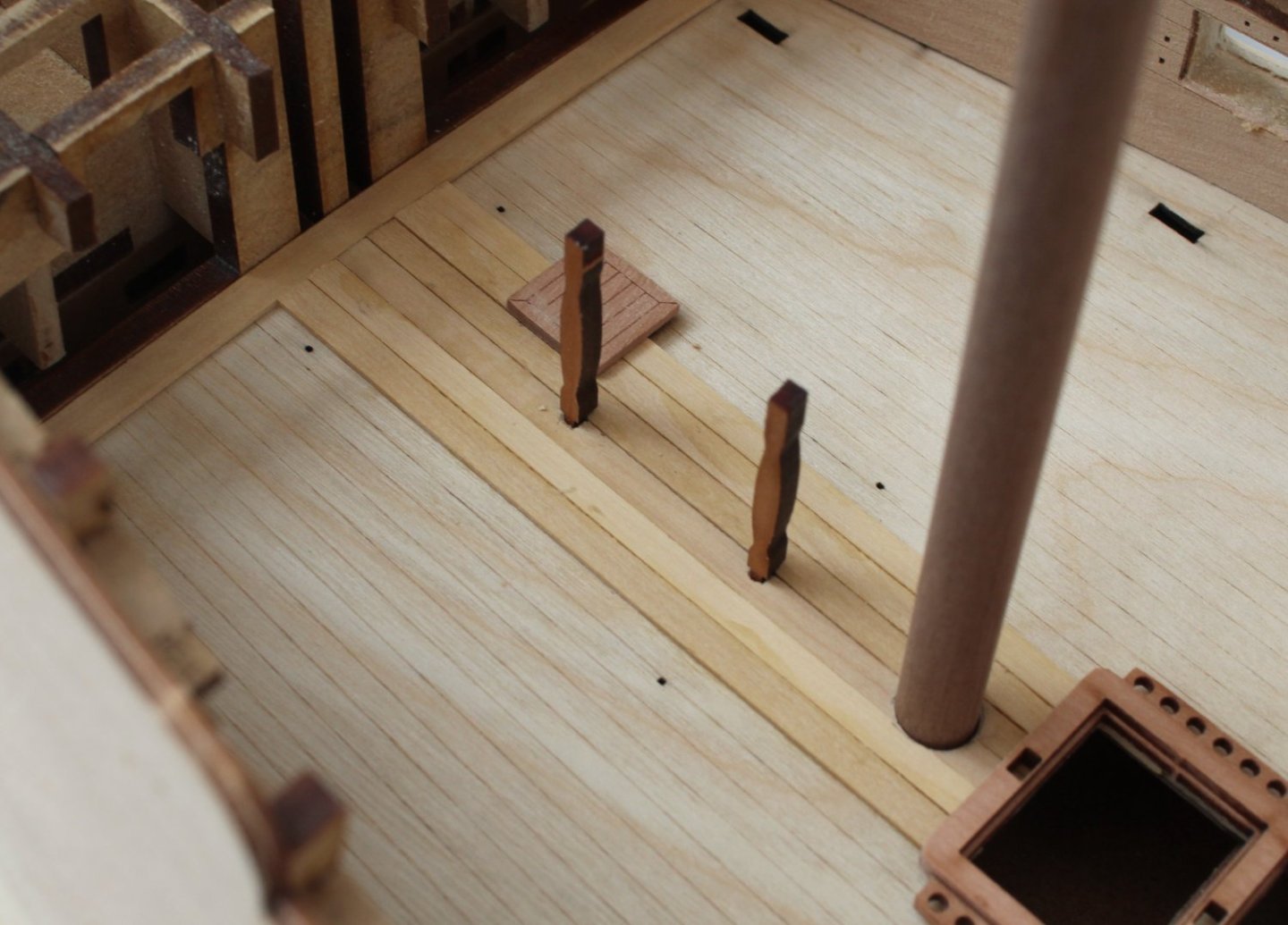
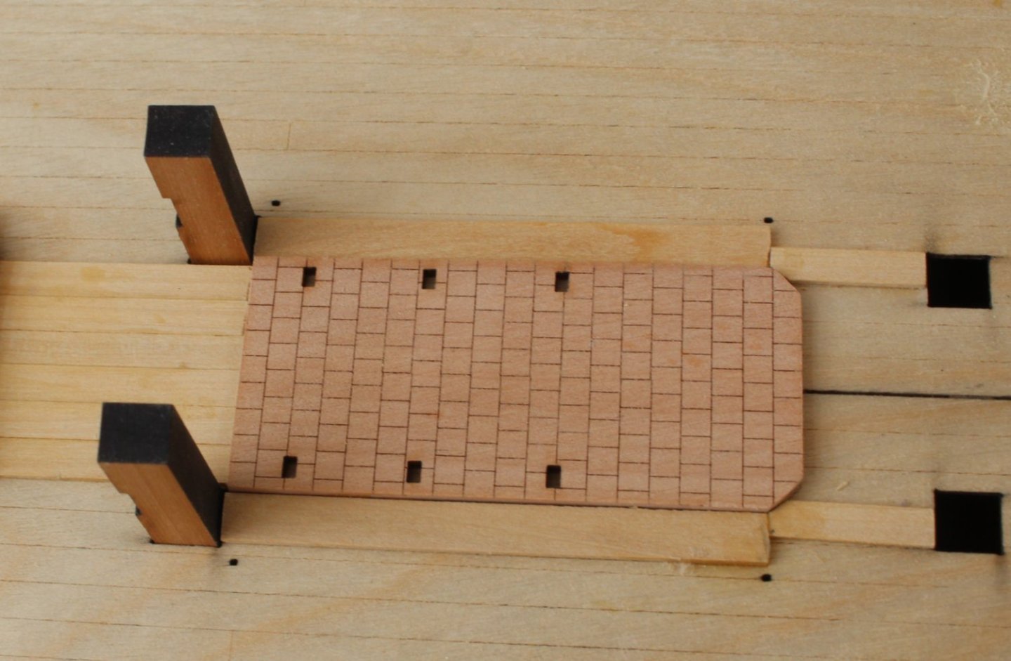
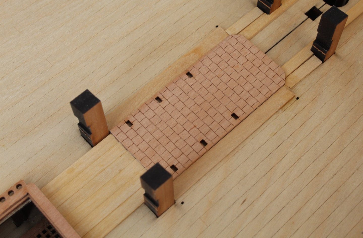
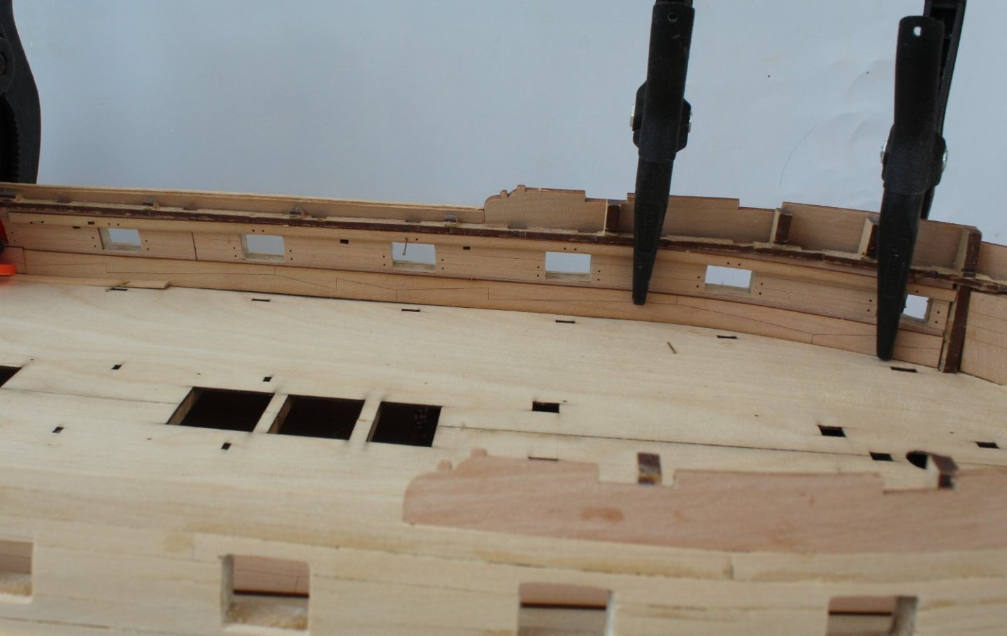
Deck Planking – Started My ongoing bulging disc is still limiting my time in the shipyard to small sessions. That said I have been able to start planking the gun deck. I started with fitting a margin plank to the stern. I then decided to plank the central section of the gun deck from stern to bow. I have not utilised a butt shift pattern due to the short plank lengths required between the various deck openings in the central gun deck area but I will use a 3 butt shift pattern for the rest of the gundeck. As each central gun deck section had been planked the various gun deck openings were opened and the associated deck items checked. I have included a set of photos showing the progress I have made over the last four days. You will note my progress is slow, but the planking is looking OK so far. The trickiest central area to plank is the stove base to the bow area. As can be seen in the next photo after some careful measurements one of the planks has had the various cut-outs added. The plank is then test fitted with the deck items in place.


- 587 replies
-
- 7
-
-
- Indefatigable
- Vanguard Models
- (and 1 more)
-
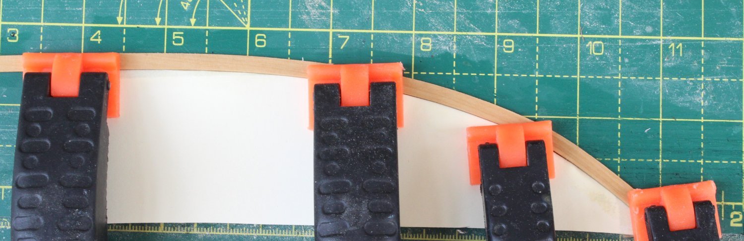
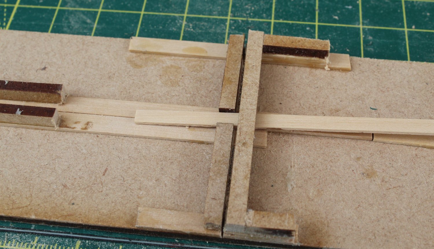
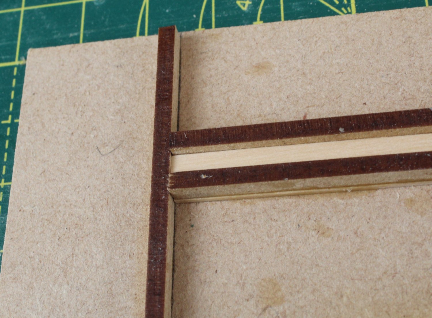
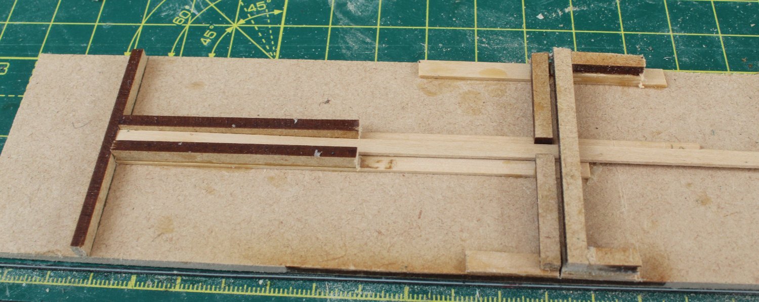
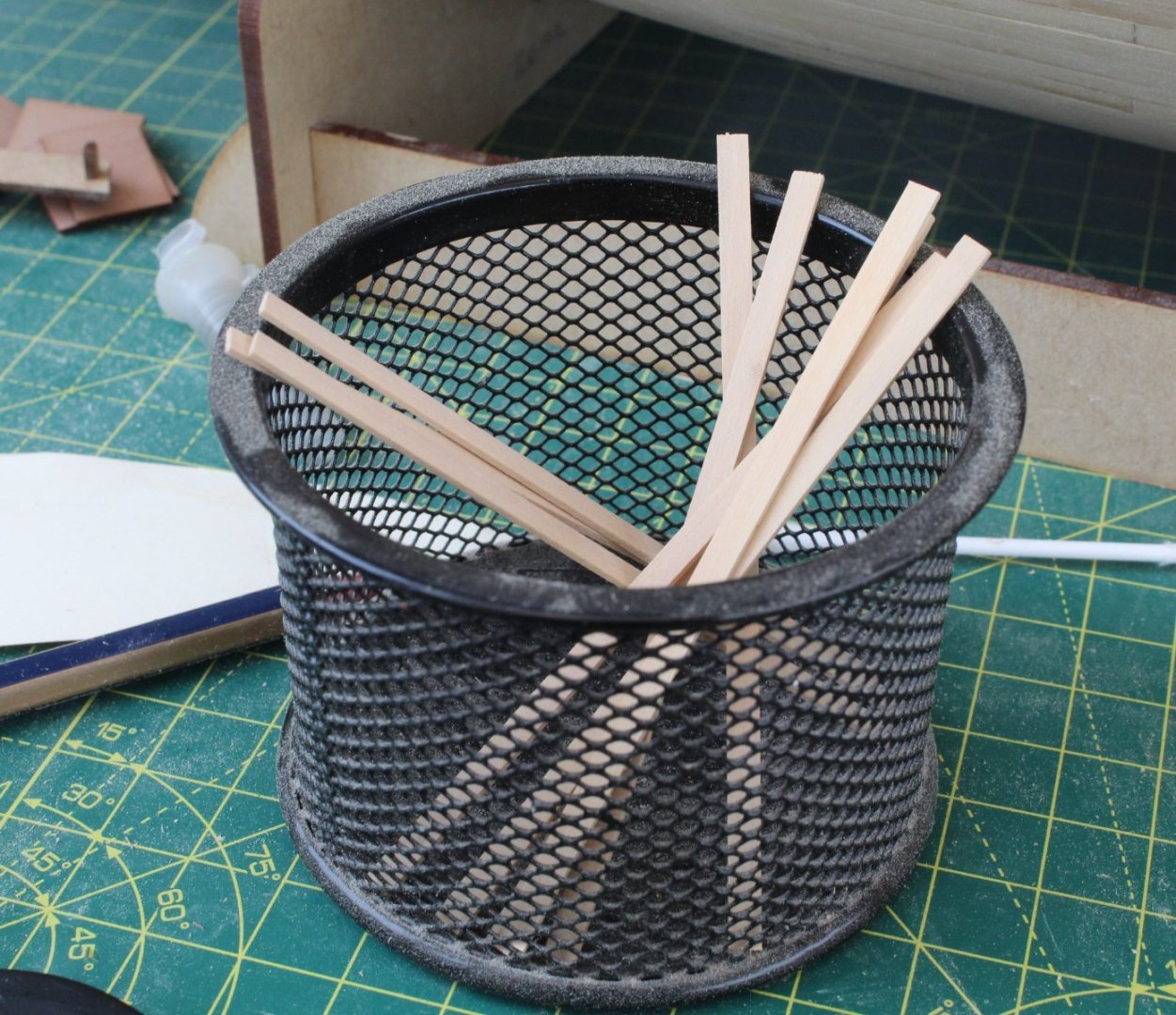
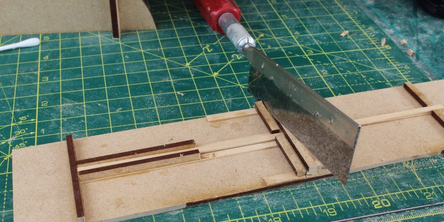
Deck Planking I ended up in A&E last week as my lower back lumber disk related condition worsened. I am now waiting for a MRI scan so the consultants can determine the nature of the problem which is probably a bulging disk. Thankfully the morphine as helped ease the back pain, however I seemed to have developed a lateral femoral cutaneous nerve pain which is still very painful when I try to walk. After a few days the pain has eased a little bit and I was able to spend a little bit of time in the shipyard today. With regards to margin deck plank for the bow area I made a template of the bow area and then clamped the plank to follow the required curve. I think this method will work. For the general deck planking I have opted to use a 3 butt shift pattern, with 100mmL planks which equates to approx. 6m long planks when scaled up to full size. To help me cut the deck planks to 100mmL I built a simple jig. In the first photo the deck plank is being fed into the jig. The plank is fed through some guide plates and is then butted up to the end stop, as can be seen in the next photo. The next photo shows the plank in position and ready to be cut to size, Using the cut slot guide the plank is cut to length using a razor saw. The various planks, when cut to size, are then place in a container ready be glued in place when needed. I have only managed to cut a few planks so far.


- 587 replies
-
- 11
-
-
- Indefatigable
- Vanguard Models
- (and 1 more)
-
Welcome to the Indy party, you've made a good start
- 233 replies
-
- 1
-
-
- Indefatigable
- Vanguard Models
- (and 1 more)
-
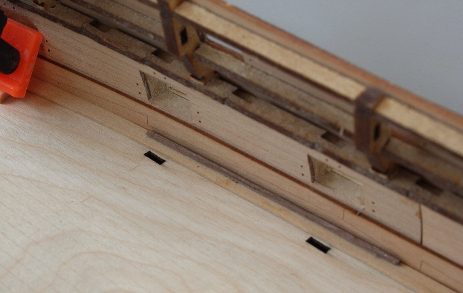
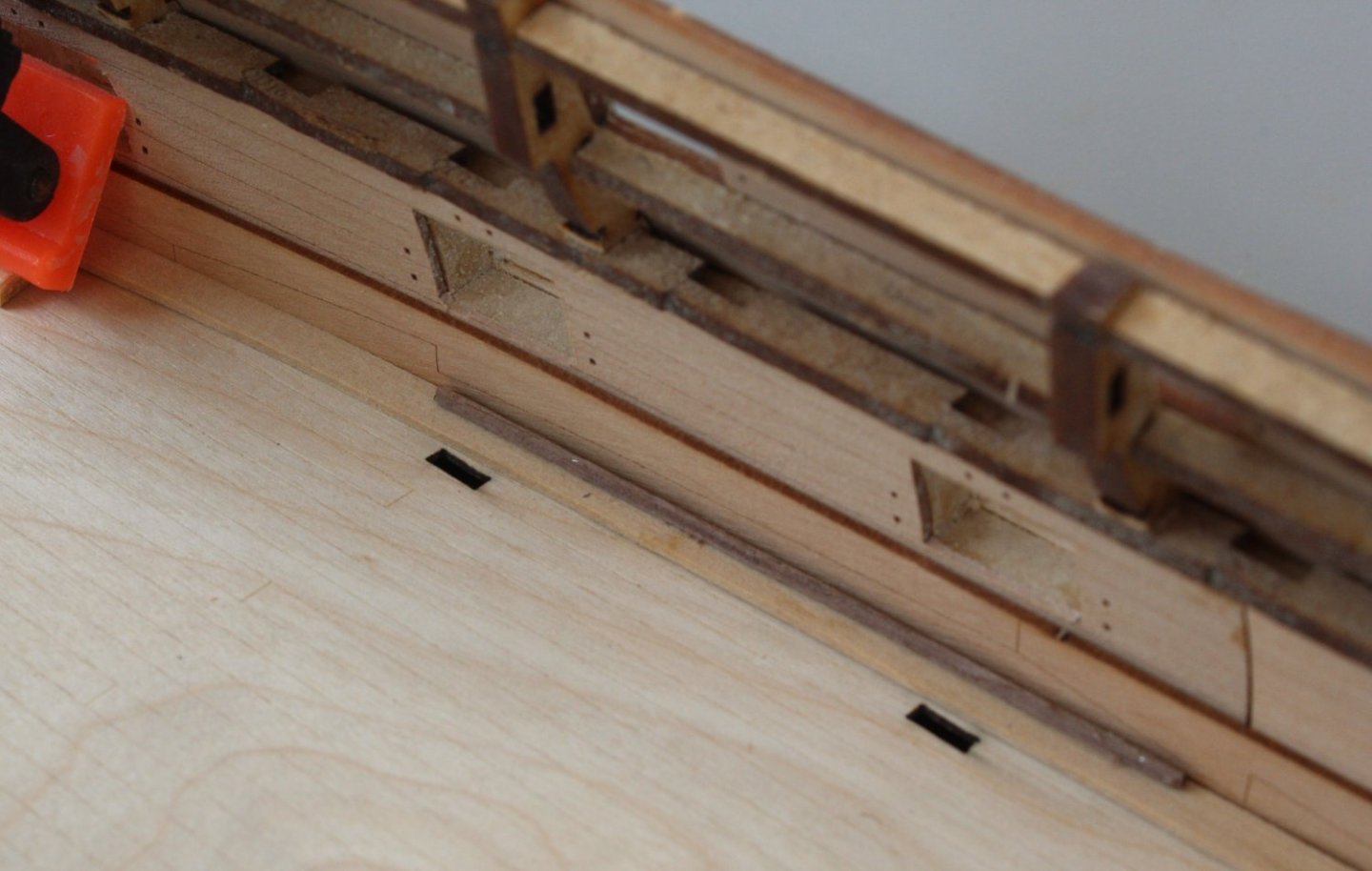
As @Blue Ensign pointed out the Spirketting is the bottom pattern as shown in the next two photos. The lateral bend of the stern margin plank is now a nice fit now as can be seen in the photo below. I have also added a test waterway section from some old walnut material. I will need to use a different wood for the waterway. I will now try to get a suitable lateral bend for the bow section

- 587 replies
-
- 10
-
-
- Indefatigable
- Vanguard Models
- (and 1 more)
-
You are right of course. In my simplistic mind both the upper and lower patterns were both called spirketting
- 587 replies
-
- 1
-
-
- Indefatigable
- Vanguard Models
- (and 1 more)
-
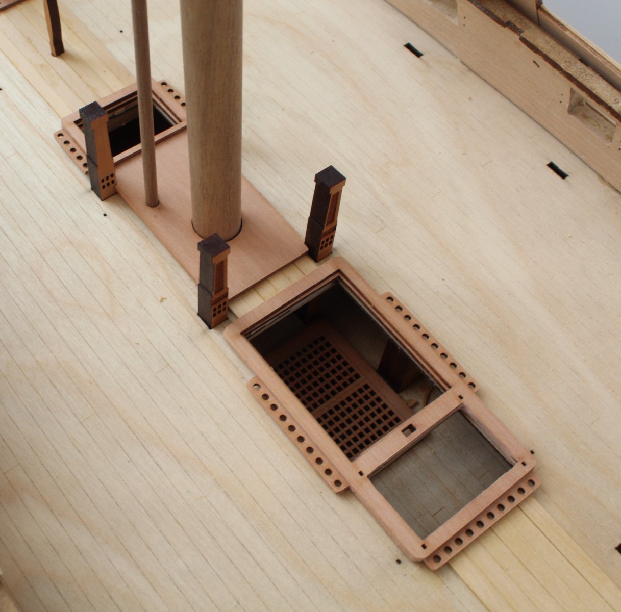
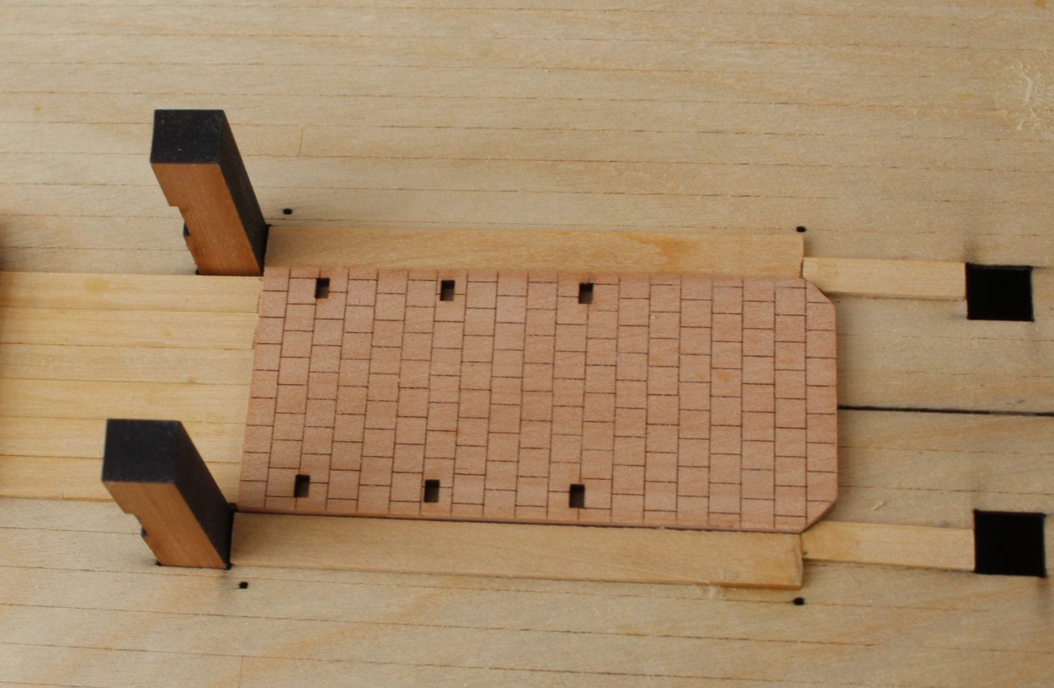
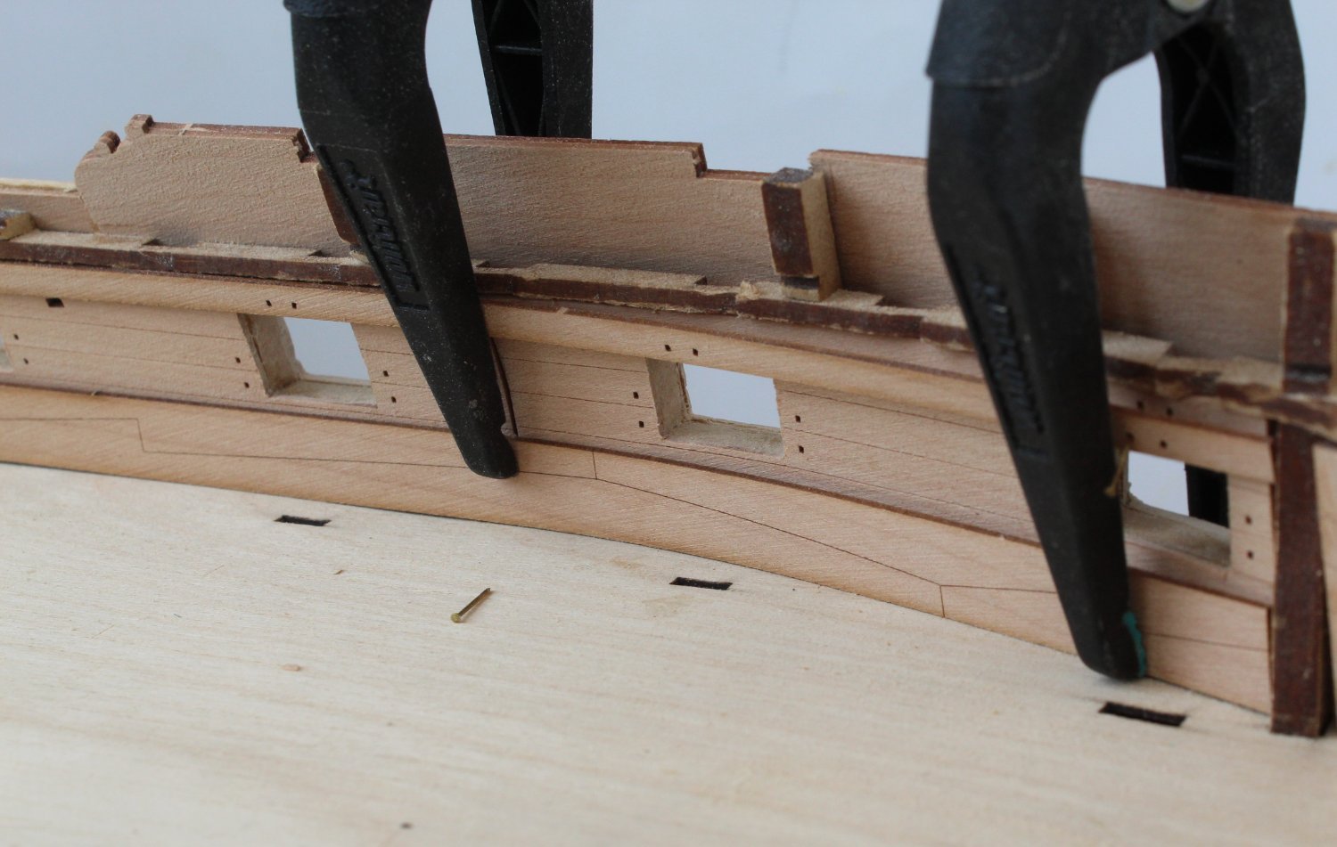
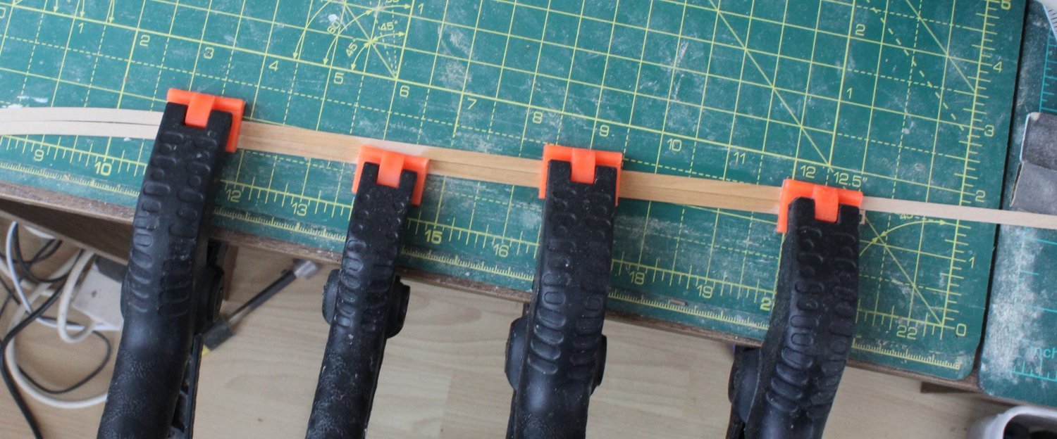
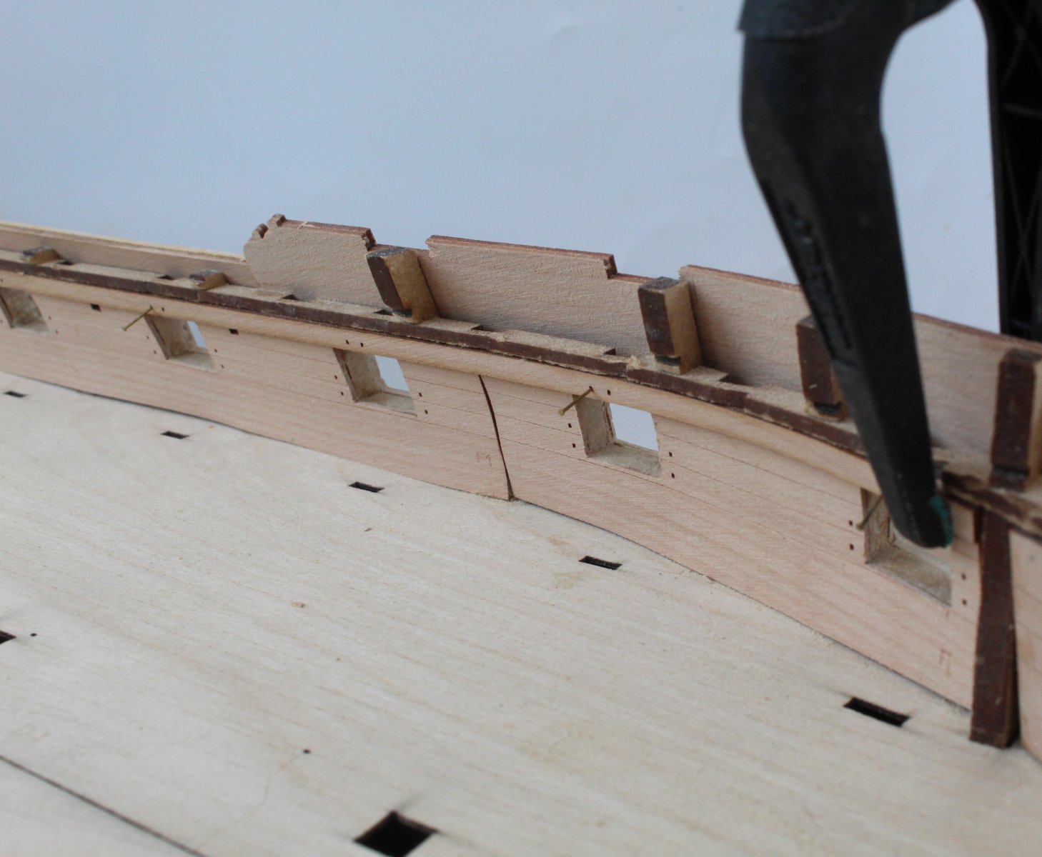
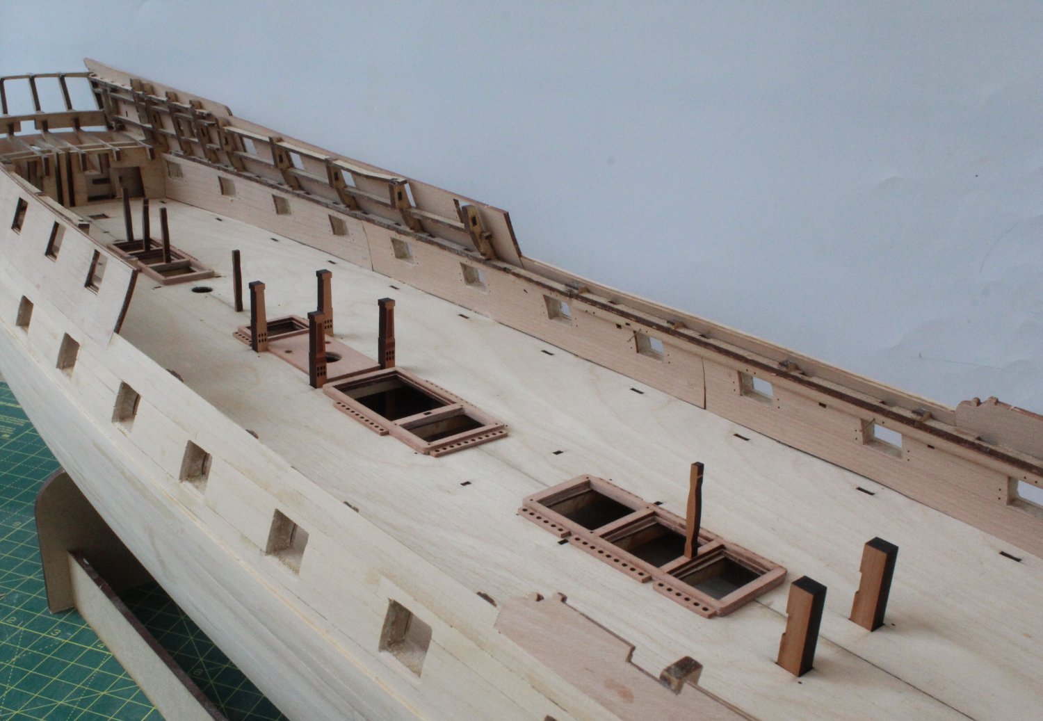
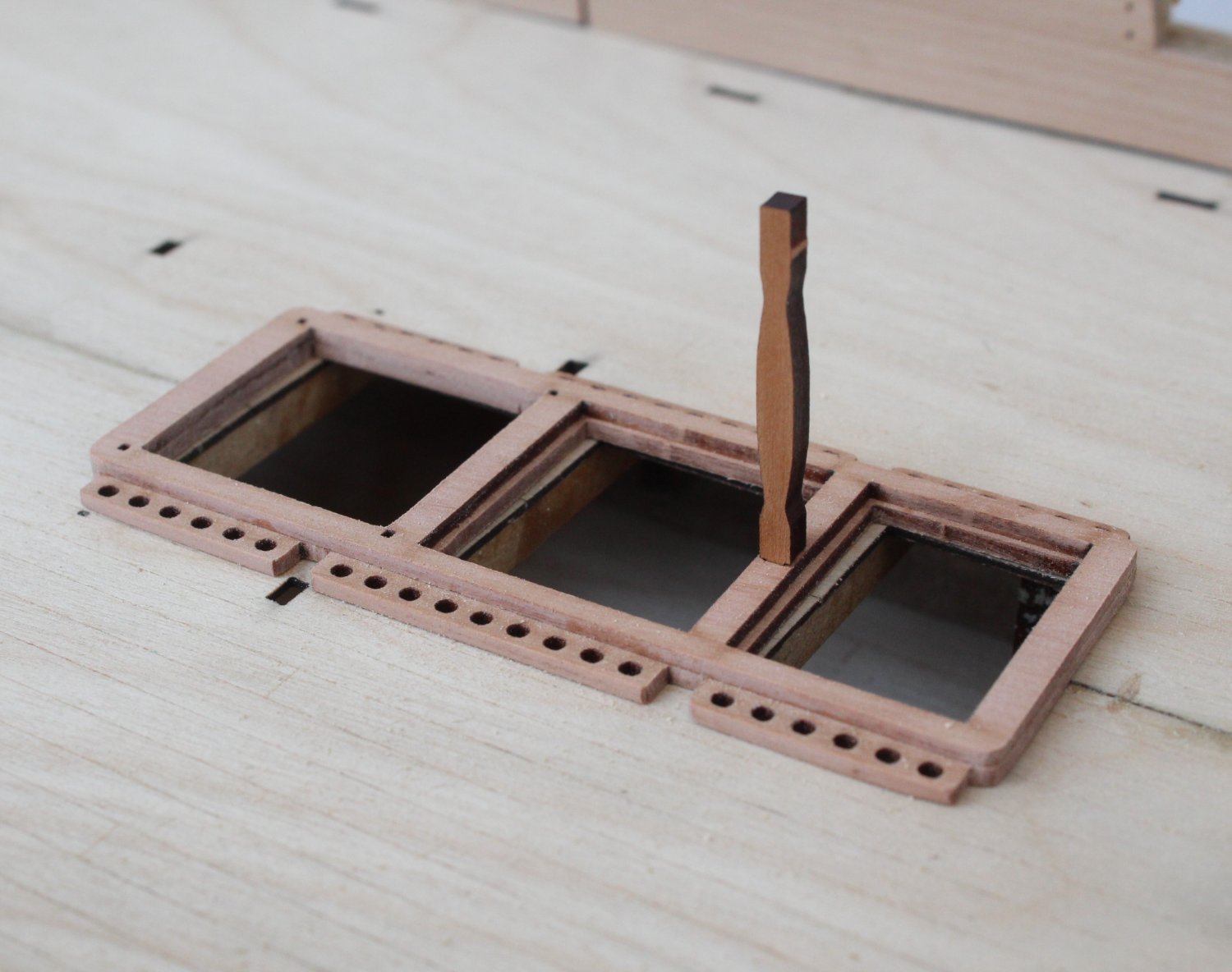
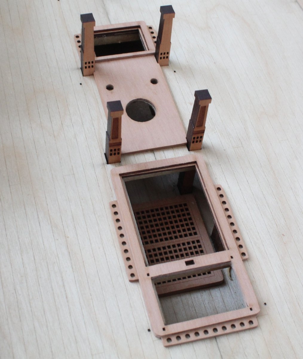
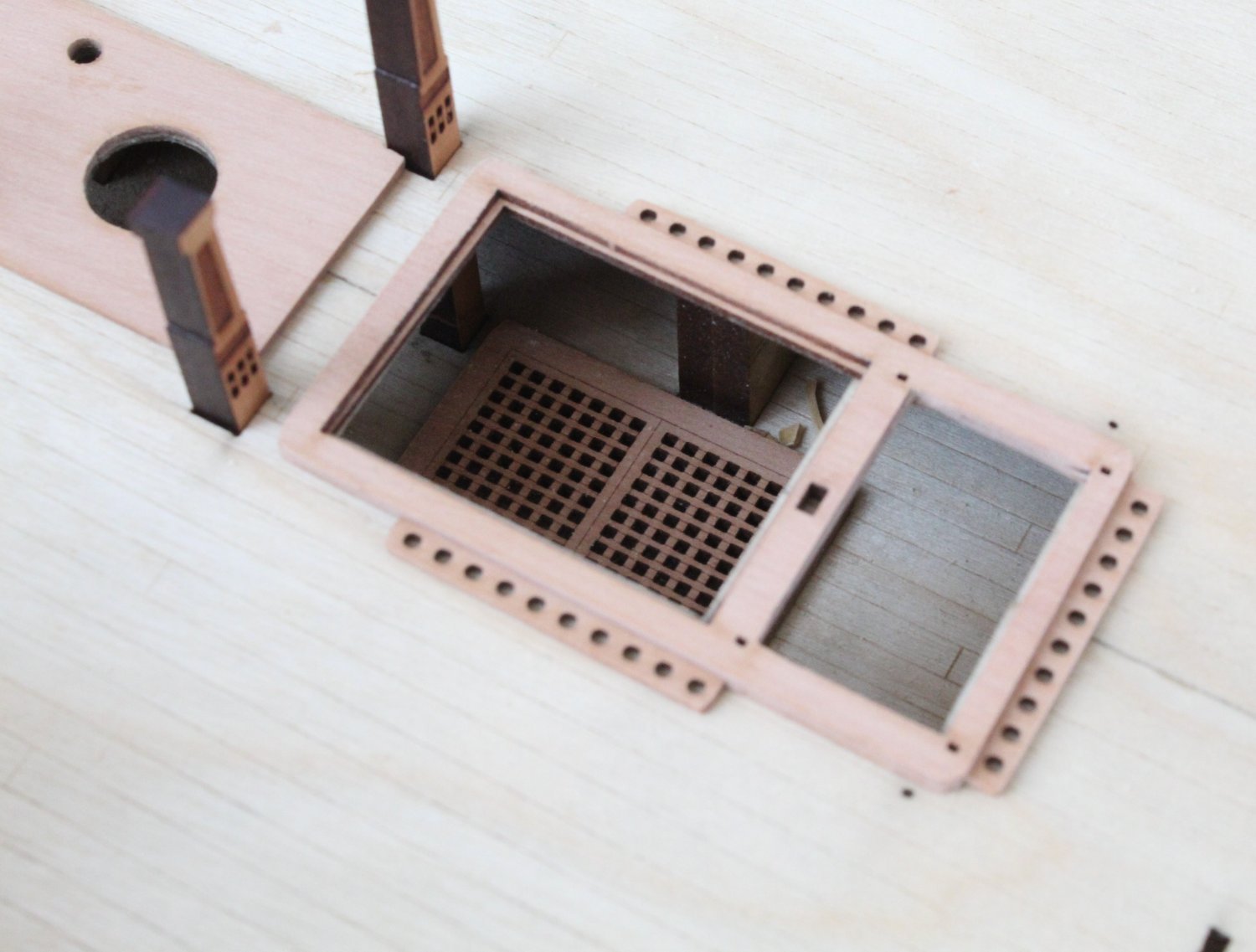
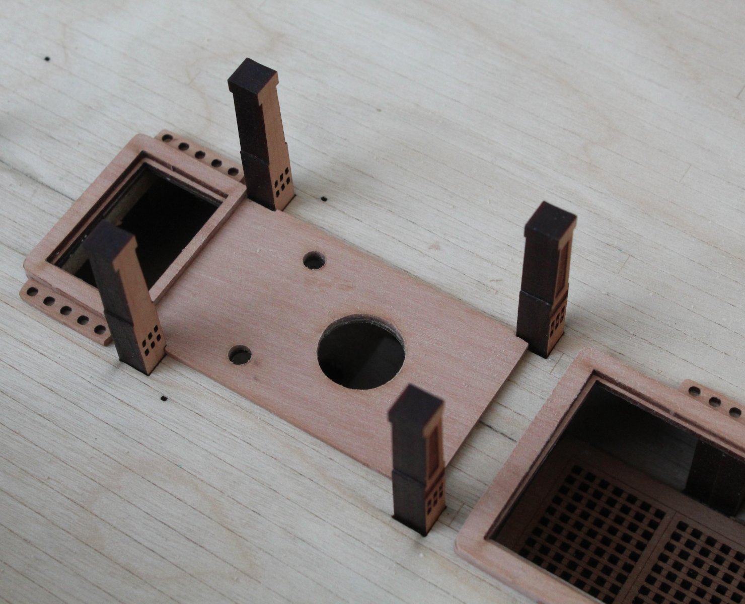
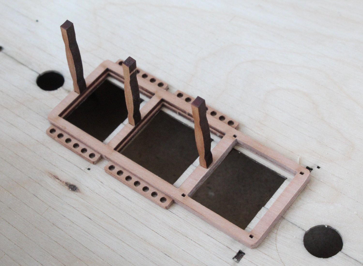
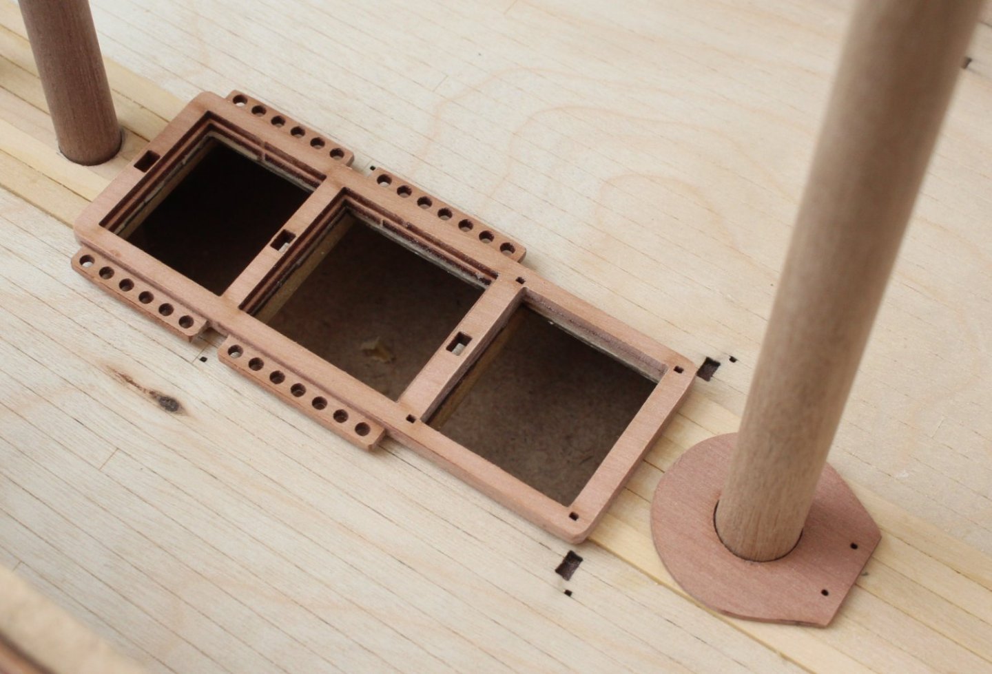
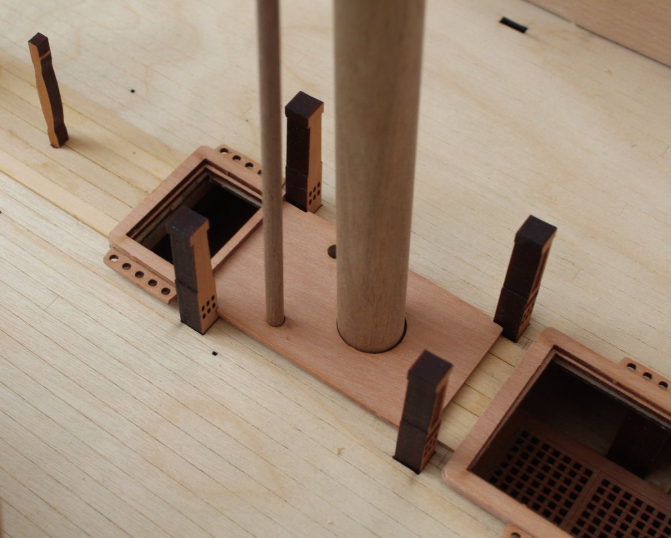
Deck Planking Preparation Work I was able to spend a little bit time in the shipyard this morning. I still to be very careful with how I move at the moment so the time spent will be short and sweet for the time being. My initial thought was to see if I could apply a suitable lateral bend for a gundeck margin bow planks. I have opted to trial 5mmW boxwood planks for the margin planks, noting the rest of the deck planking would be done using 4mmW boxwood planks. I soaked two 5mmW planks in hot water for around 45 minutes and then I applied a sharp bend to these planks, as shown in the photo below. When I did a test fit of these bent planks around the bow area I realised I would need to add a much sharper bend. It may take two or three interations of the bending process to get the required bend for these planks. However when I checked these planks with the stern section the bend was just about right, but a minor adjustment would be needed. The planks were clamped again and I then brushed on some water. These planks will now be left to fully dry out. Once I am happy with the stern margin planks bend I will soak and bend margin planks for the bow section. While the planks were immersed in the hot water I did a trial fit of the Spirketting. In the photo below the left-side front pattern has been test fitted. I used some brass pins to help with the alignment with the eyebolt holes. I had previously constructed the gundeck grating assemblies, noting they still need to be painted. I did this because if I decide to plank the deck with the boxwood planks then I would like to make sure the grating assemblies are a good tight fit once the planking is complete. I decided it would be nice to take a few photos of them on the deck. It was nice to see the grating assemble for the main mast area is a good fit with the bitts. The main mast and pump holes also are nicely aligned.


- 587 replies
-
- 5
-
-
- Indefatigable
- Vanguard Models
- (and 1 more)
-
I agree it is the silly movements that catch me out. I was well on the way to recovery last week then as I reached for my socks last Thursday the prolapse reacted. Fingers crossed it has settled back down again but I'm being very carful with my movements.
- 587 replies
-
- 1
-
-
- Indefatigable
- Vanguard Models
- (and 1 more)
-
Thanks for all the kind comments, it is greatly appreciated.
- 587 replies
-
- 4
-
-
- Indefatigable
- Vanguard Models
- (and 1 more)
-
An Enforced Break - Planning Ahead I am in the unfortunate position of taking an enforced break from the Indy as I have suffered a relapse of prolapsed disk in my lower back last week. I first suffered the prolapsed disk around 20 years ago when I bent over an desk to look at an engineering drawing. This time it was due to over extending myself whilst in the garden trimming a large hedge, bending over as I was sweeping up the debris. The back is now starting to respond to the rest so hopefully I can return to the shipyard in the next few days for short periods of time. The time away from the Indy build means I am spending more time thinking of my next course of action with regards to the gundeck planking and spirketting which is to be added to the bottom of the inner bulwark patterns. I have the option of either fitting the laser etched deck pearwood part or to plank with the 4mmW box wood planks. I could take the easy approach which is to fit the laser etched deck followed by the spirketting. If I take this course of action the first task would be to paint the inner bulwarks (except where the spirketting would be located). Once the inner bulwarks had been painted the laser etched gundeck pattern would be fitted followed by the spirketting. The spirketting would also need to be painted. I have already made a cardboard template of the bow area which I can use to check and trim the laser etched deck part as necessary should I opt to fit this part. Alternatively I could start by adding the spirketting. The laser etched gundeck would then be added after the bulwarks and spirketting have been painted. The task would be completed by adding a waterway using some rounded 2mm square timber. Another option I have been considering, after adding the spirketting to the inner bulwarks, is to use the boxwood timber to plank the gundeck, using a 3 or 4 butt shift pattern. I would have to look at adding a margin plank to the edge next to the spirketting. Once the planking is complete I would then add a waterway with some 2mm rounded material. This option would be much more challenging as I would need to bend the margin planks laterally for the bow area. I am also going to laterally bend a plank to see if I can get the required amount of bend. Given the bow area is more or less hidden by the forecastle deck I could probably get away without adding a laterally bent margin plank and to simply butt the plank edge to the spirketting. The other challenging aspect with this approach would be to include the cannon locating slots. I would need to assembly one cannon to ensure the locating slots are correctly sized. Of course I could simple plank over the slots and to remove the tabs from the cannons. The cannon could be glued in place with a flat edge added to the bottom of the wheels.
- 587 replies
-
- 8
-
-
-
- Indefatigable
- Vanguard Models
- (and 1 more)
-
Thanks. I just need to be careful at the moment and try to avoid moving too fast or twisting which hopefully will settle the prolapse to recovery quickly.
- 443 replies
-
- 6
-
-
- Indefatigable
- Vanguard Models
- (and 1 more)
-
Your Indy is really looking nice. I'm currently taking an enforced break from my Indy due to a reoccurance of a prolapse in my lower back (a slipped disc). I liked your boxwood planked gundeck so I am pondering weather to follow suit or to fit the laser etched part.
- 443 replies
-
- 5
-
-
- Indefatigable
- Vanguard Models
- (and 1 more)