Glenn-UK
-
Posts
3,175 -
Joined
-
Last visited
Content Type
Profiles
Forums
Gallery
Events
Everything posted by Glenn-UK
-
 Such a shame for you. I did wonder about having one side bare and one side copper on my model just for the contrast.
- 443 replies
-
- 7
-

-

-
- Indefatigable
- Vanguard Models
- (and 1 more)
-
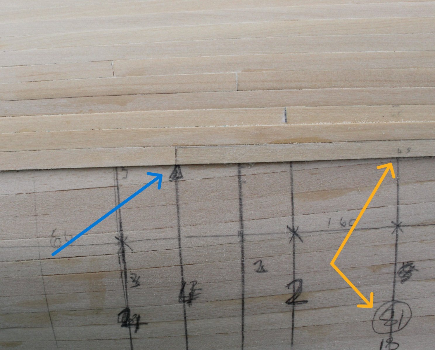
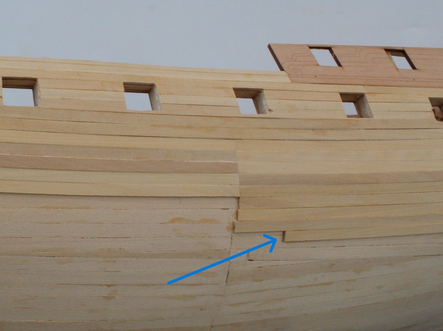
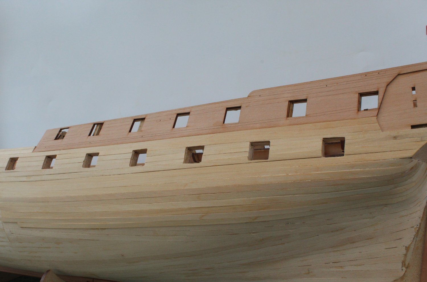
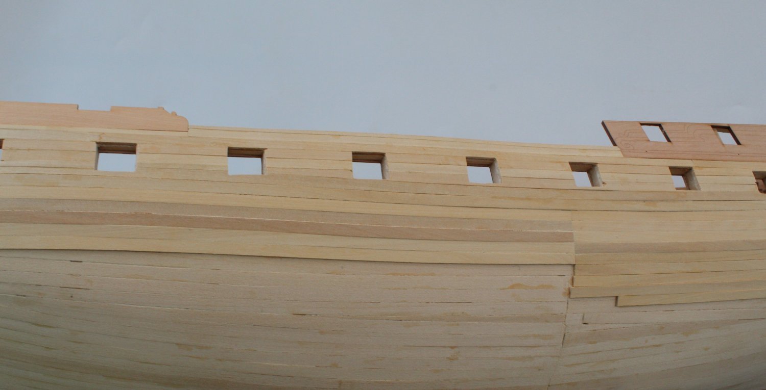
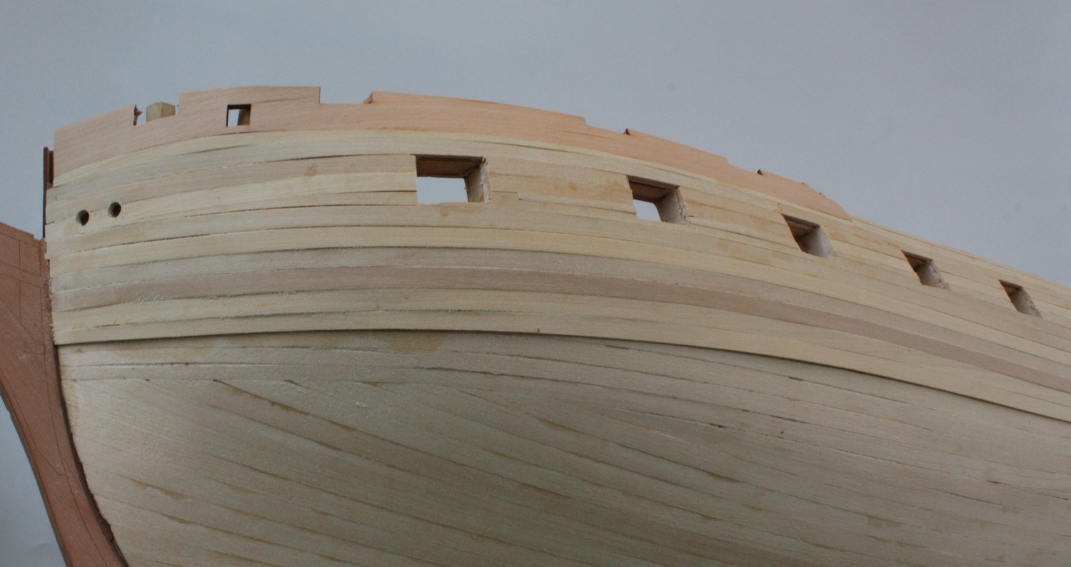
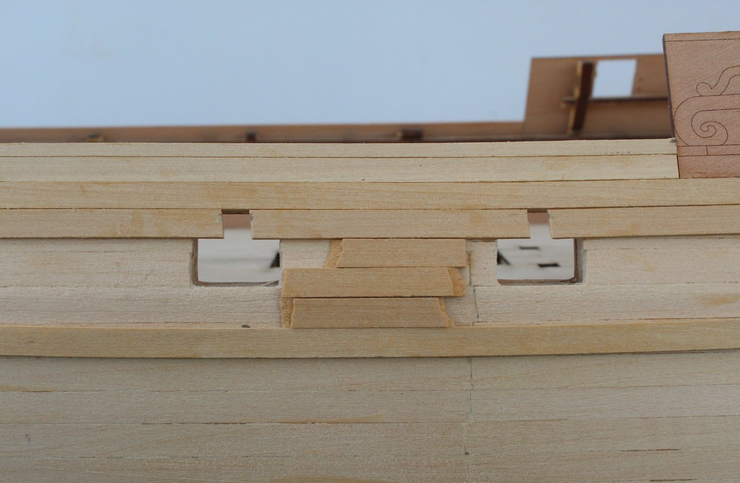
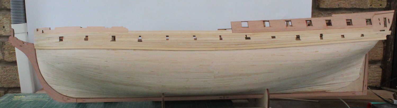
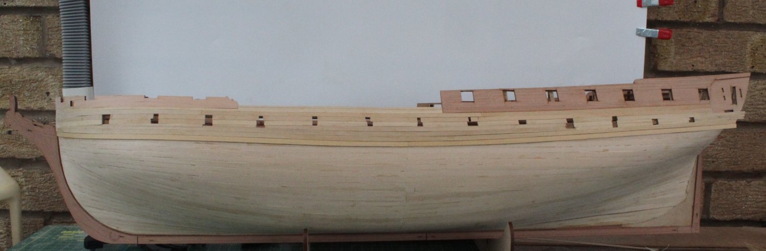
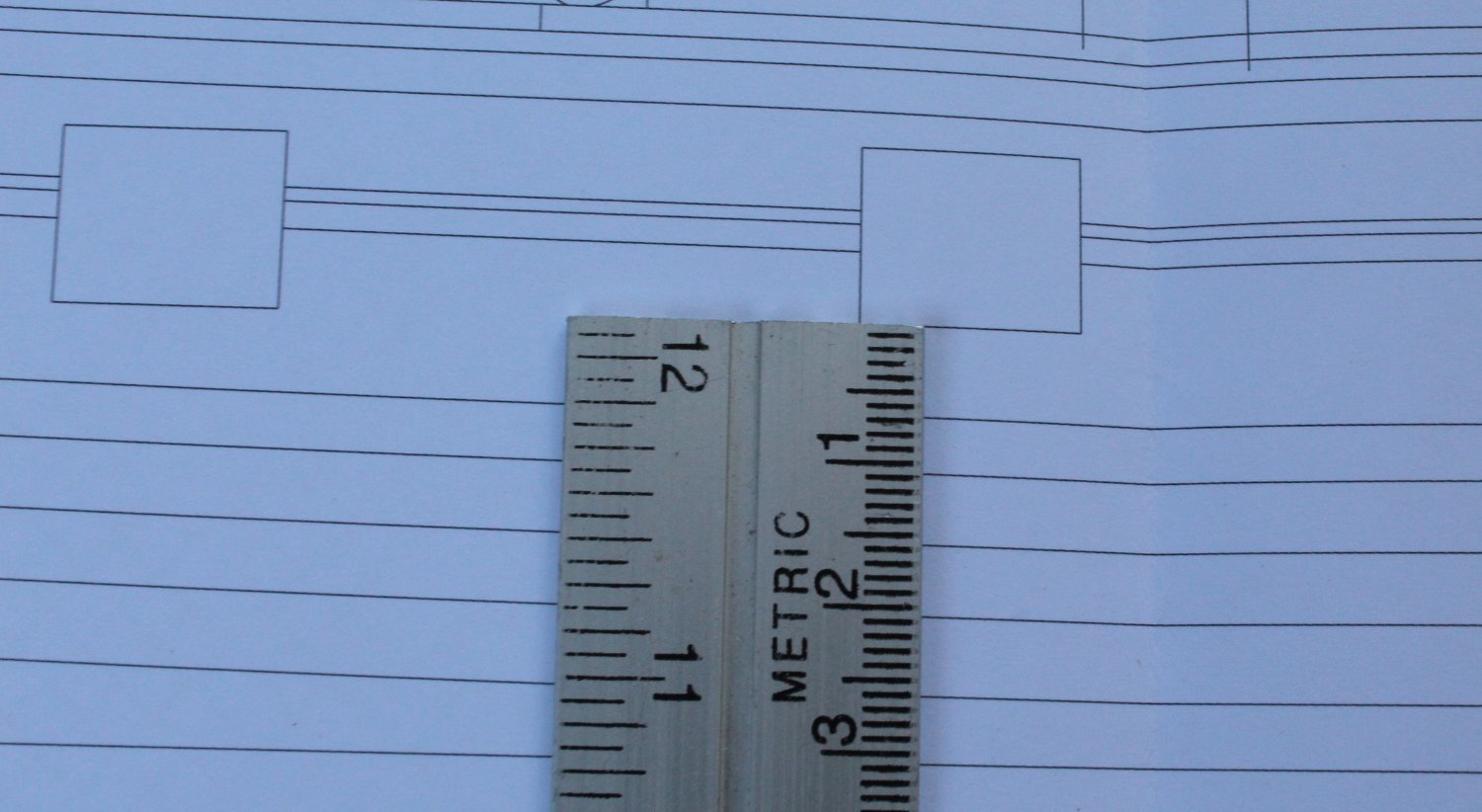
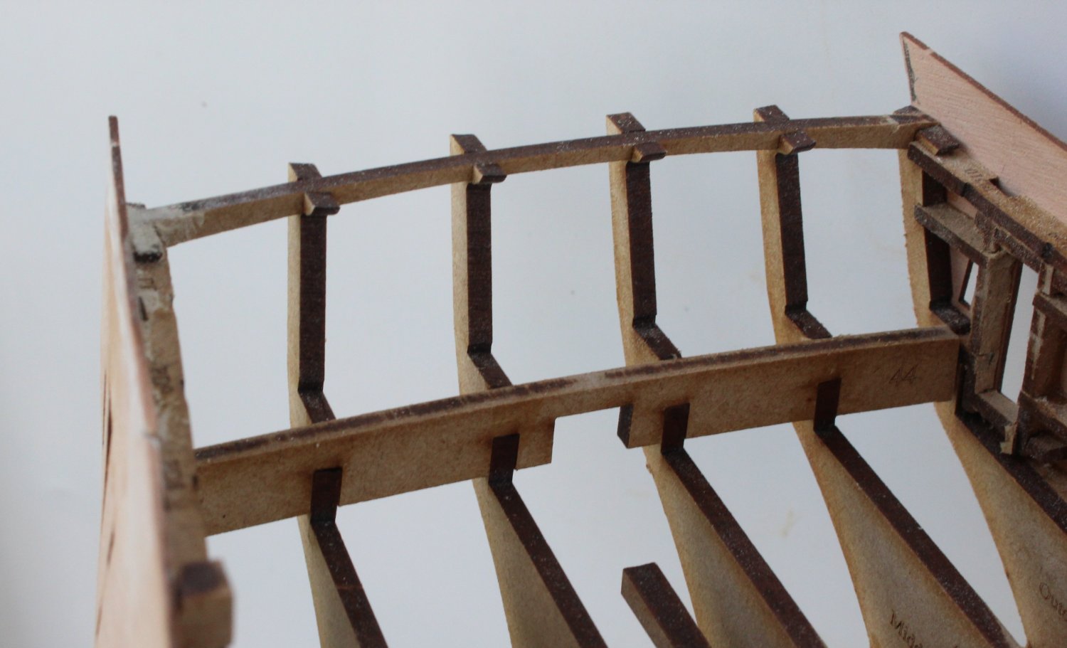
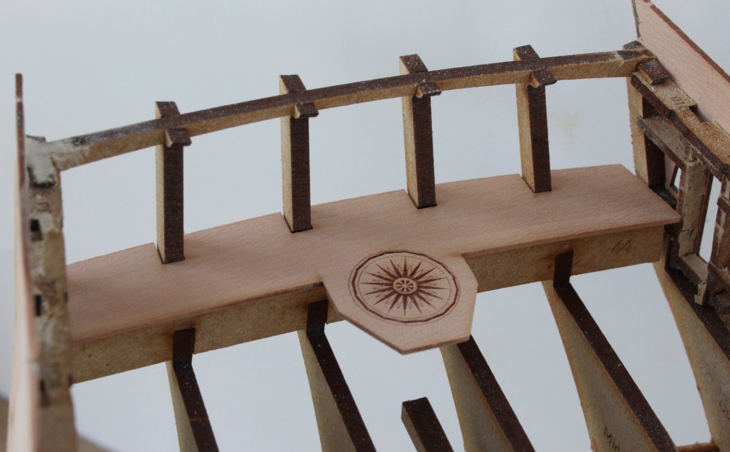
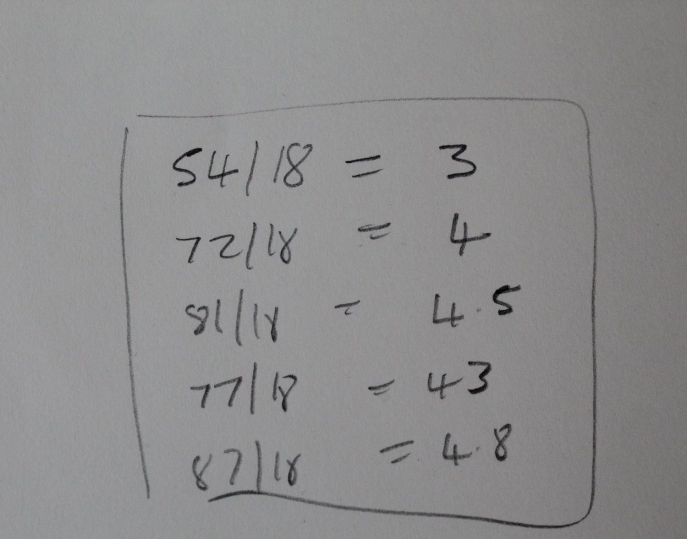
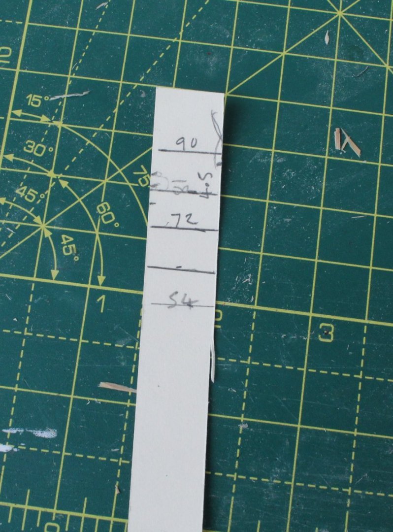
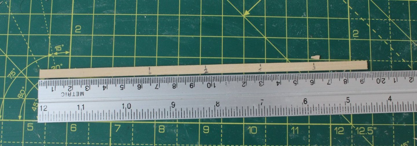
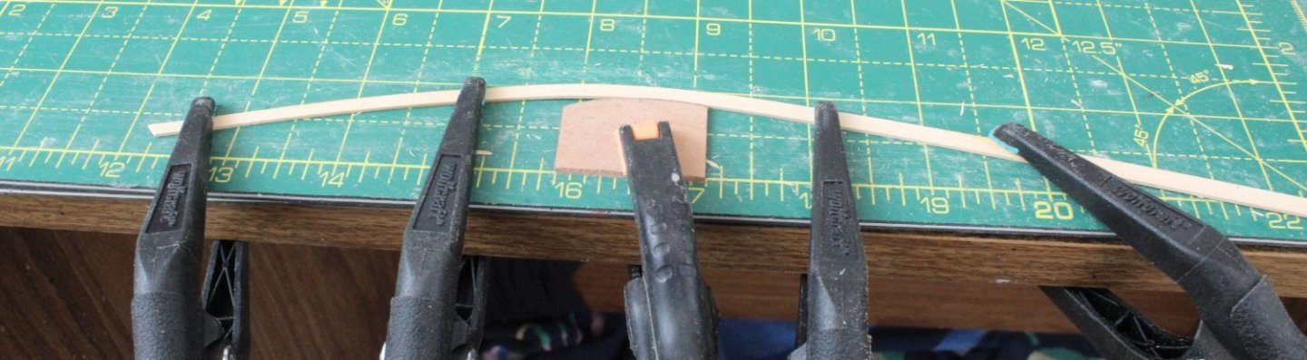
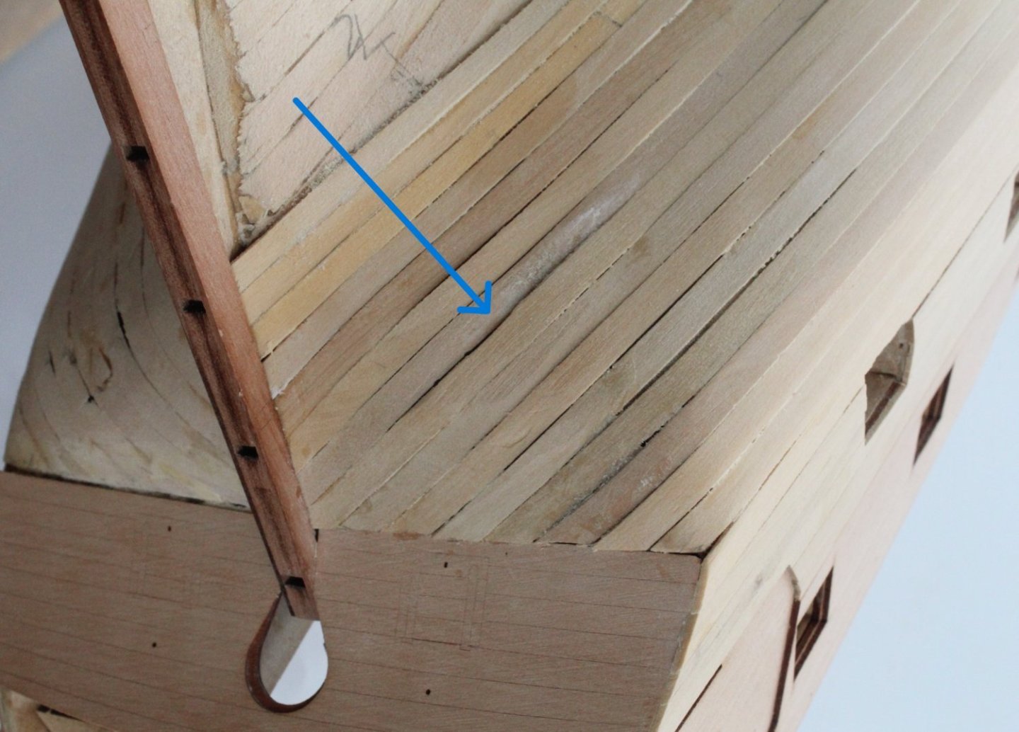
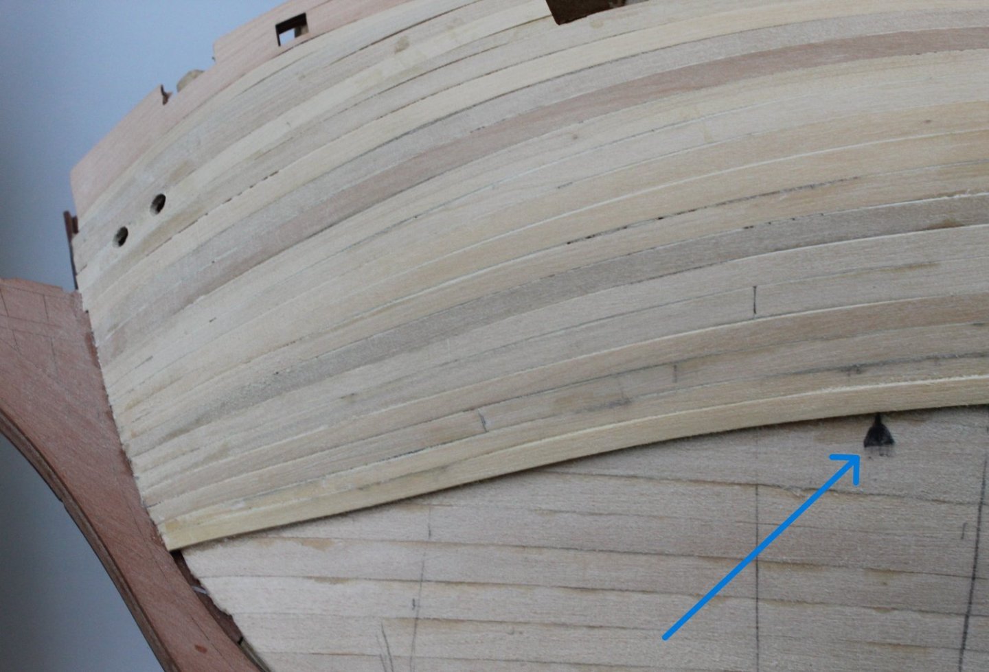
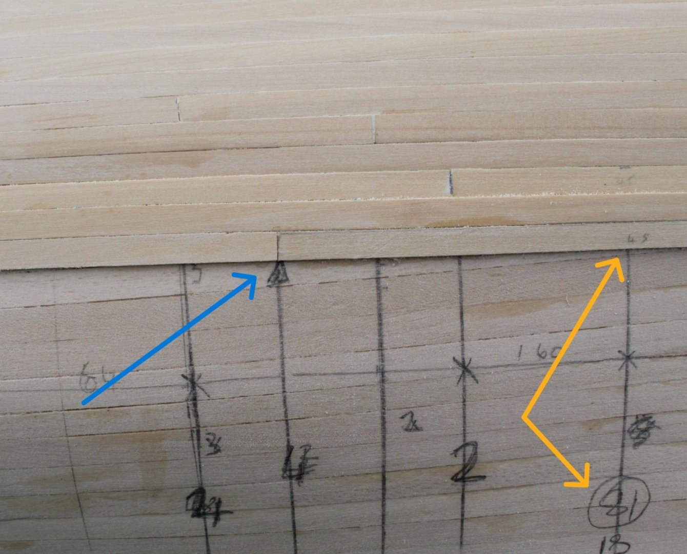
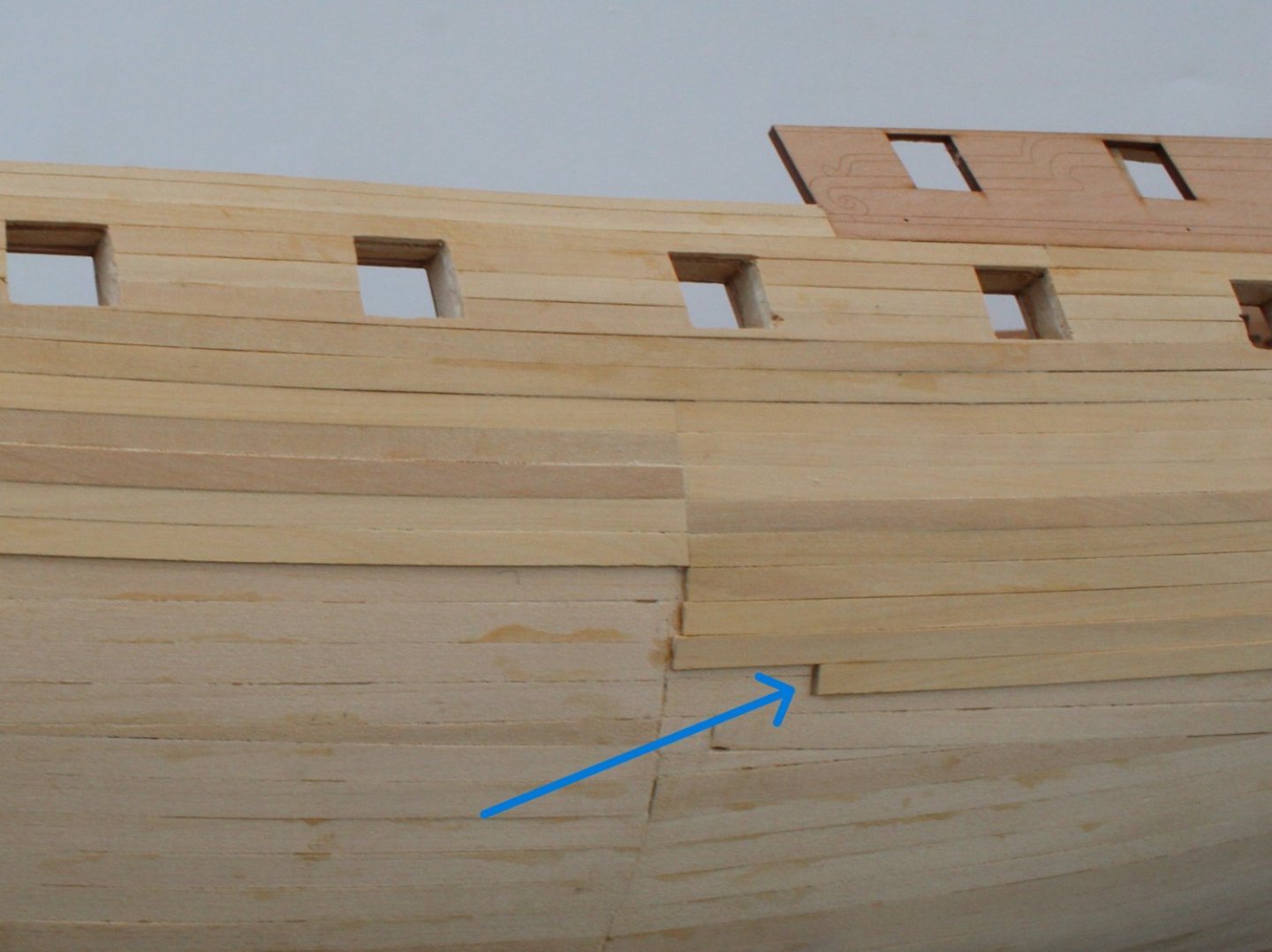
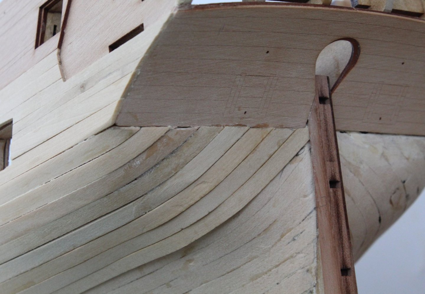
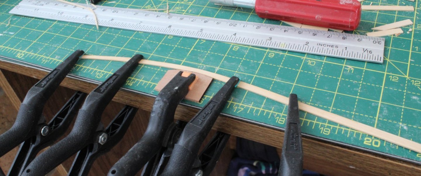
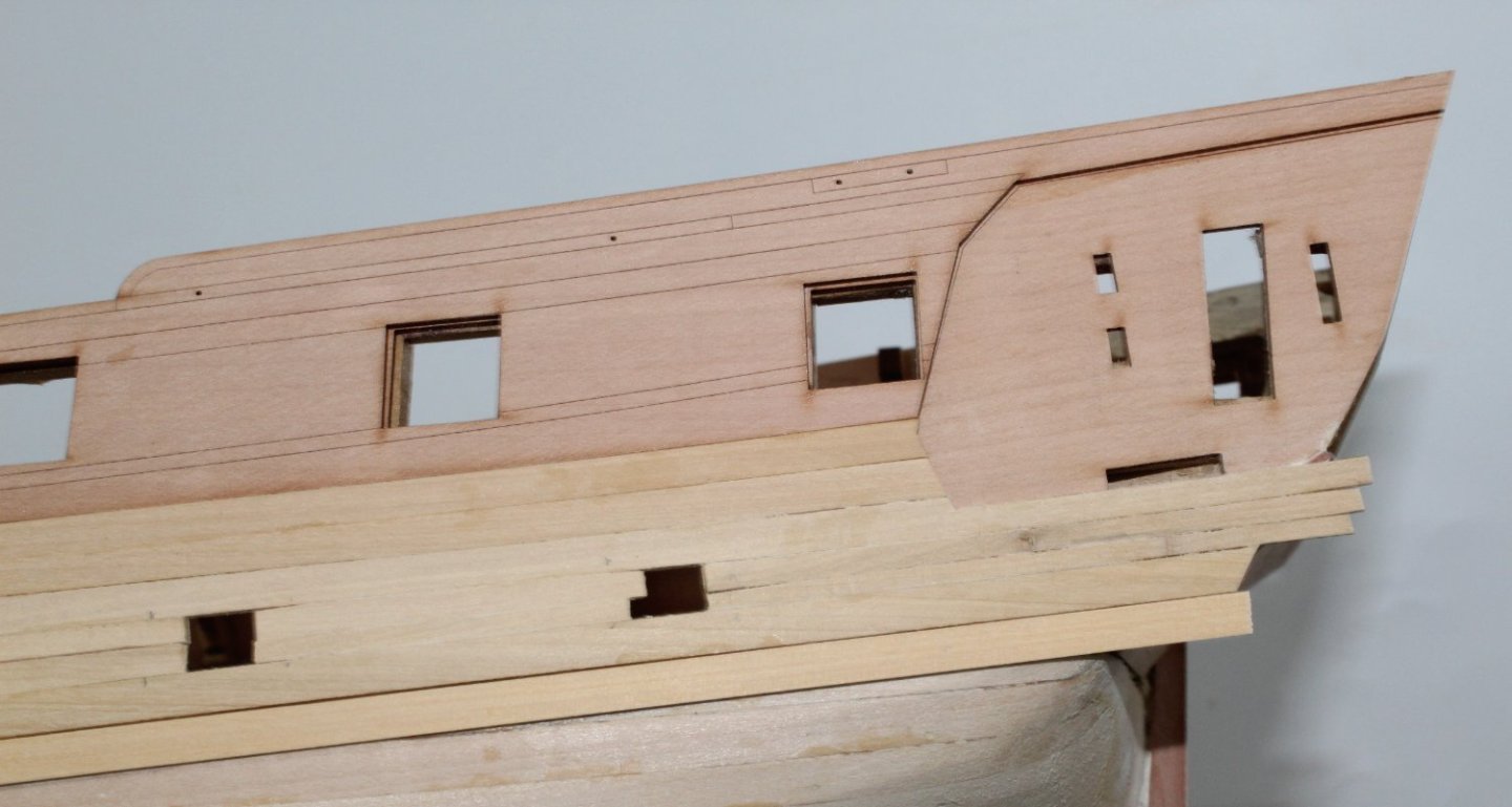
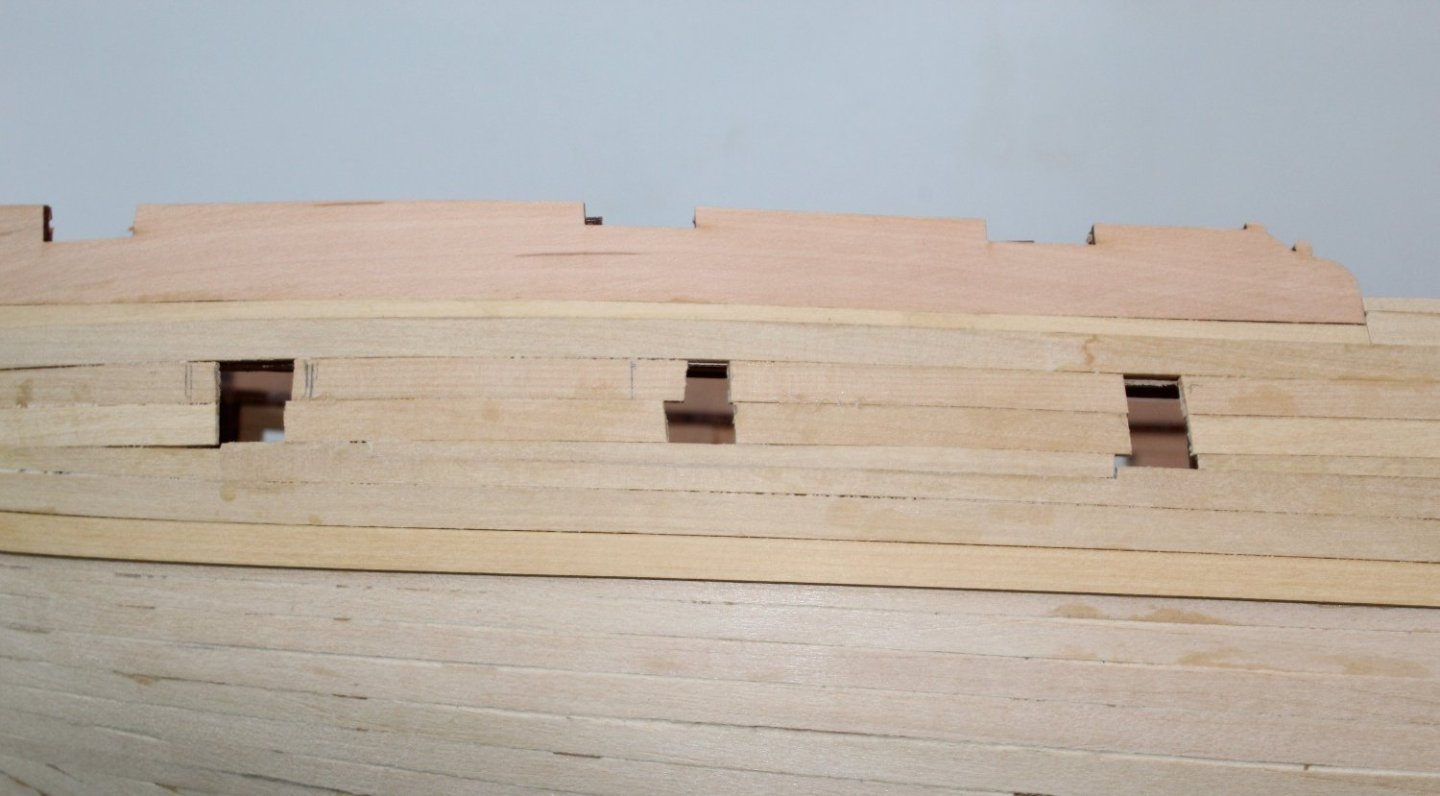
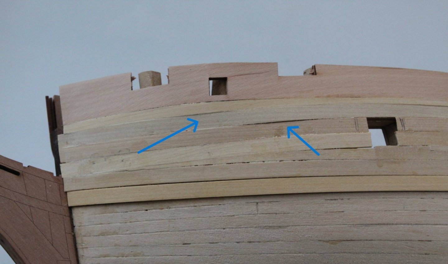
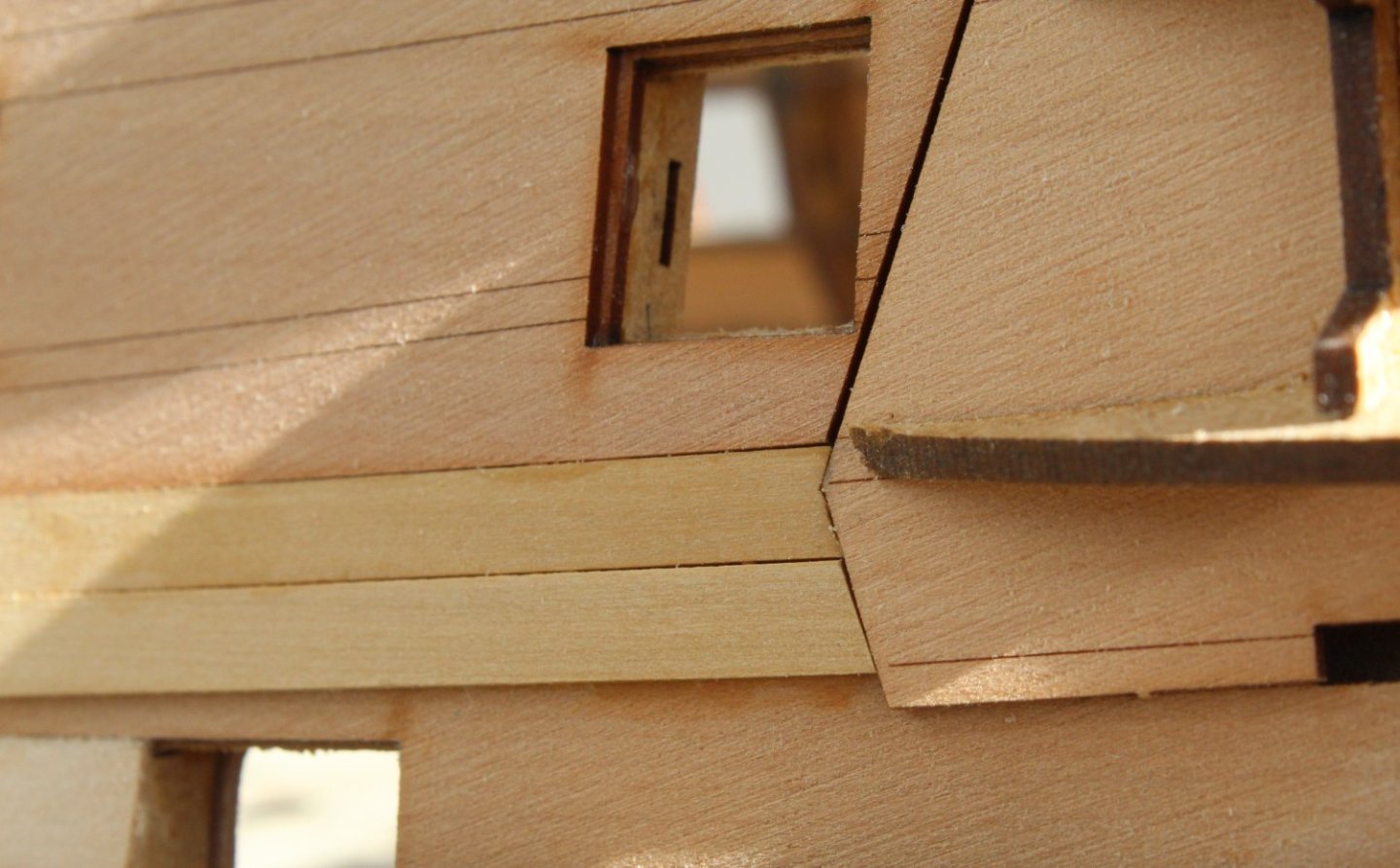
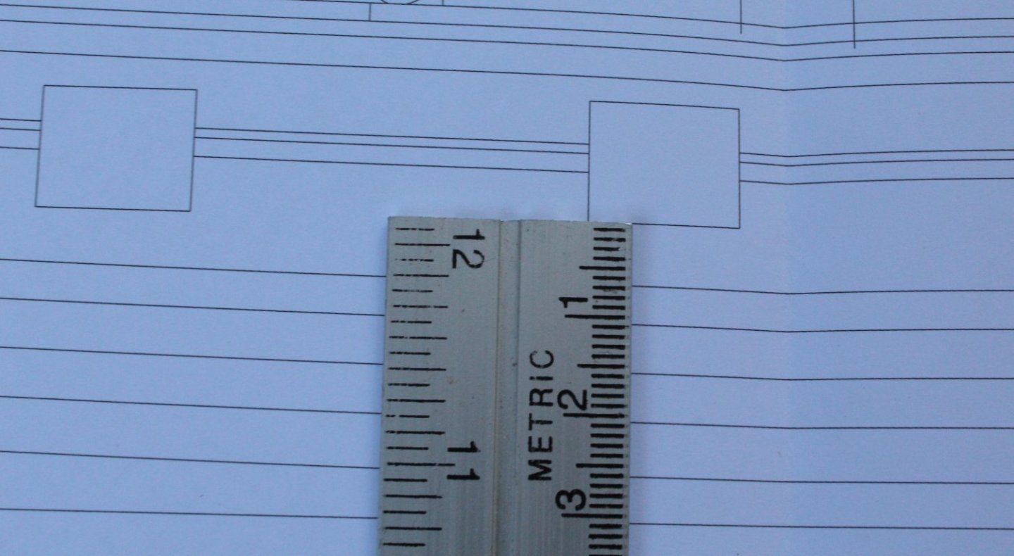
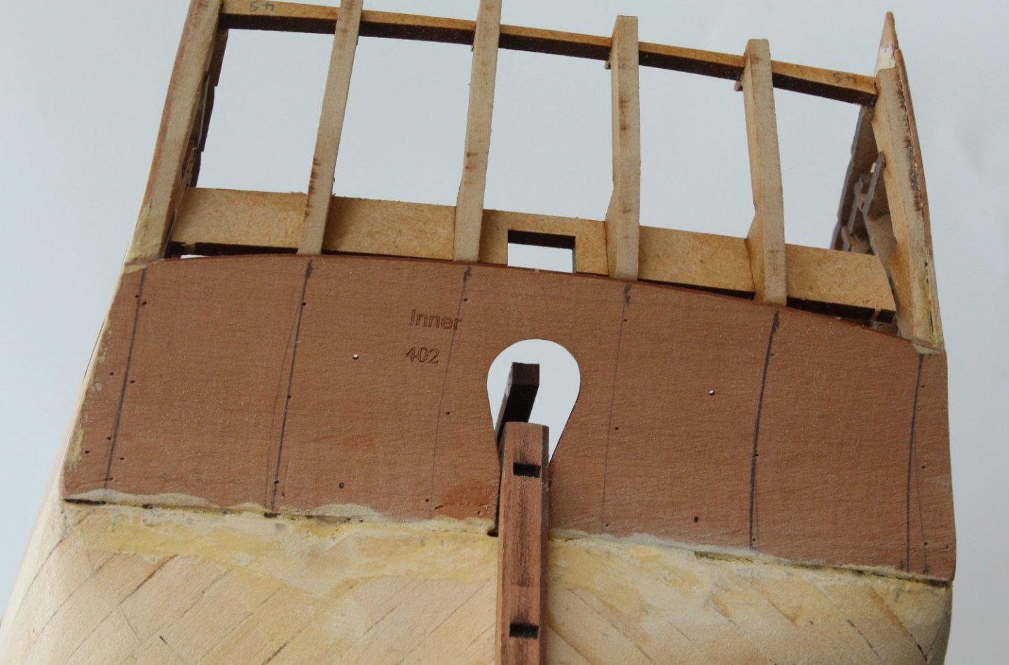
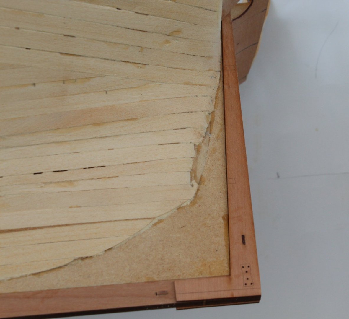
Second Planking – 4 Butt Shift Hull Planking As the planking continues on the left-hand side very slowly I have now moved on to using a 4 butt shift pattern when fitting the planks. Historically hull planks seemed to be 5 to 6m long which equates to approx. 94cm at 64th scale. I decided that the plank lengths would be best suited to a 4 butt shift pattern arrangement if the plank lengths were divisible by 6, e.g. 96mm. After a bit of experimentation with spreadsheet arrangements I decided to double the plank lengths to 192mm and came up with the following plan. After fitting three planks up from the keel, I determined the maximum infill area would be 90mm, thus requiring 18 full width 5mm planks. For easy of tapering planks I made some simple calculations, as can be seen in the next photo. I then made a template based on the calculations to mark the positions on the hull for 54mm (3mm), 72mm (4mm) and 81mm (4.5mm). The 4.5mm became necessary as the planks taper towards the stern down to 4mm and then from that point to the stern post requires reverse taper back to 4.5mm. The 4.5mm reference also became an important taper reference point between the 5mm and 4mm run from midships toward the stern. As I started to add the planks I found it beneficial to have a template 192mm long plank with marks set for the planking sequence. For the bow planks I am taking a plank a long length and applying the required taper. Next I apply the lateral bend, as can be seen in the next photo. When I am happy with how the plank looks I trim the plank into the required lengths. The next photo shows the stern area, which looks Ok apart from one plank which caused me no end of problems to get a decent fit (blue arrow). In the end I decided to live with it as this area will be painted black so filler will hide the bad workmanship. The next photo shows the stern area. I have never planked a bow area this well before but it is certainly not of a high standard. The blue arrow indicated where the next plank join will be. The final picture shows where a plank join is on the marker (blue arrow). It also shows the 81mm (4.5mm plank width) position (yellow arrows).
- 587 replies
-
- 10
-
-

-
- Indefatigable
- Vanguard Models
- (and 1 more)
-
I did not look at any plans. I found that the hull plank repair work on HMS Victory were 6m long, click link for description. Also found a reference on Ships Of Scale which mentioned 5 to 6m lengths. With my limited knowledge I therefore assumed max plank length would be 6m
- 587 replies
-
- 1
-
-
- Indefatigable
- Vanguard Models
- (and 1 more)
-
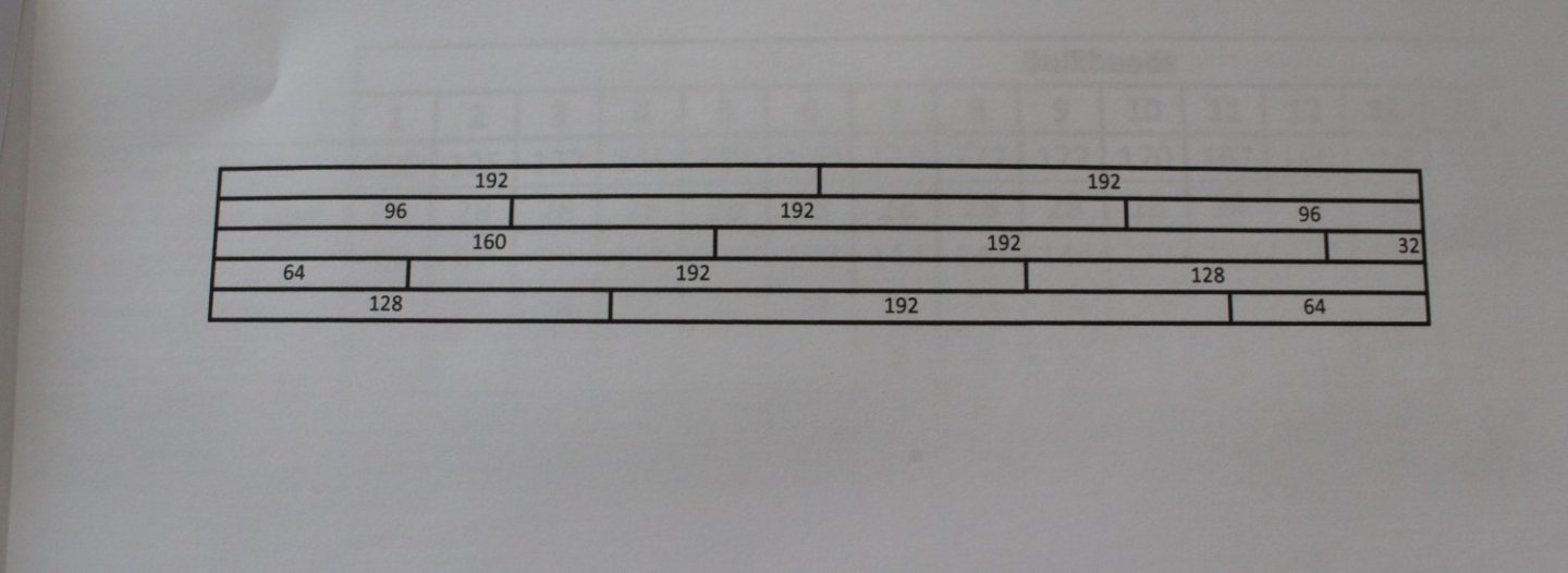
Once I have checked where the approx. position of the waterline and assuming I have not already starting planking below the waterline I might switch to a 4 butt shift pattern. This means, when completed, if the boxwood planking looks Ok I might leave as bare wood rather than covering with the copper. From a little bit research it would appear the typical hull plank length would be 5 to 6 metres. 6m would equate to 94cm at 64th scale (6000/64 = 93.75). I understand the 4 butt shift pattern follows a bulkhead sequence 1 - 3 - 5 - 2 - 4. First plank starts at 1. The next full plank beneath would start at position 3, next full plank beneath would then start at position 5, next would start at position 2 and then position 4 before the sequence repeats again. Therefore if I make each full plank 96mm (which is divisible by 6 and a length of 16mm per position) then I will have a nice repeatable sequence for the 4 butt shift pattern as can be seen in the attached picture and pdf file. I would welcome any comments if my research / calculations are in error. 4 Butt Shift.pdf

- 587 replies
-
- 3
-
-
-
- Indefatigable
- Vanguard Models
- (and 1 more)
-
I had already started to shift the joint position. Maybe not as much as you have suggested, many thanks for the great advice. The top area will be filled, sanded and painted so will probably not be that noticeable. Depending on how the planking turns out below the water line it will either be left as planked or I will add the copper tiles. I had been considered adding planks lengths of 90 to 100mm to simulate 6m ship planks with a 4 butt shift pattern
- 587 replies
-
- 4
-
-
- Indefatigable
- Vanguard Models
- (and 1 more)
-
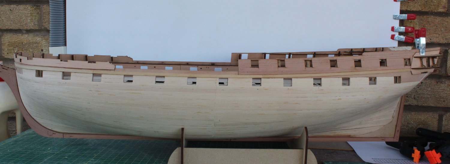
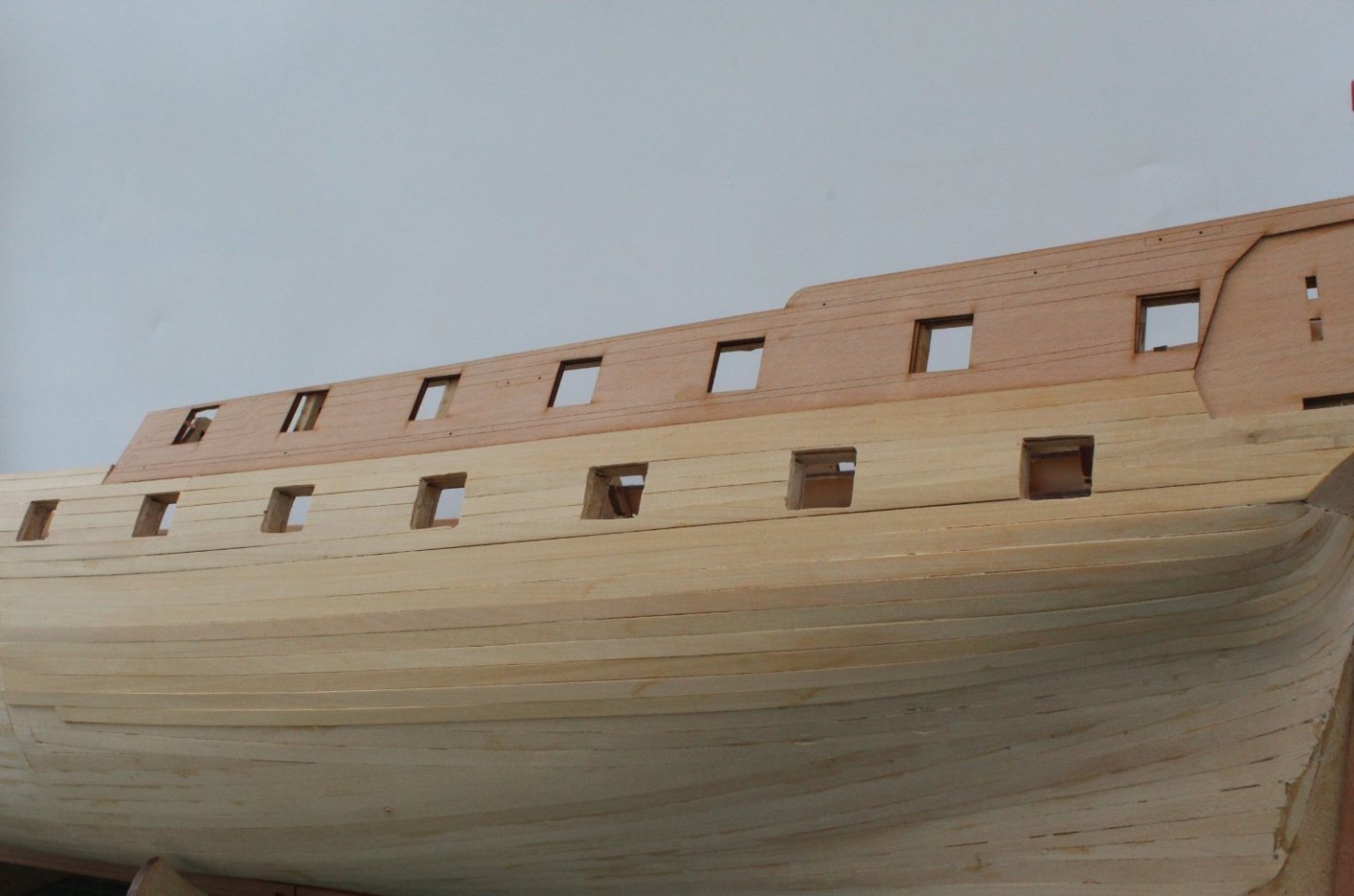
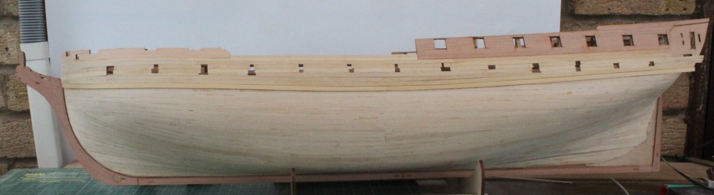
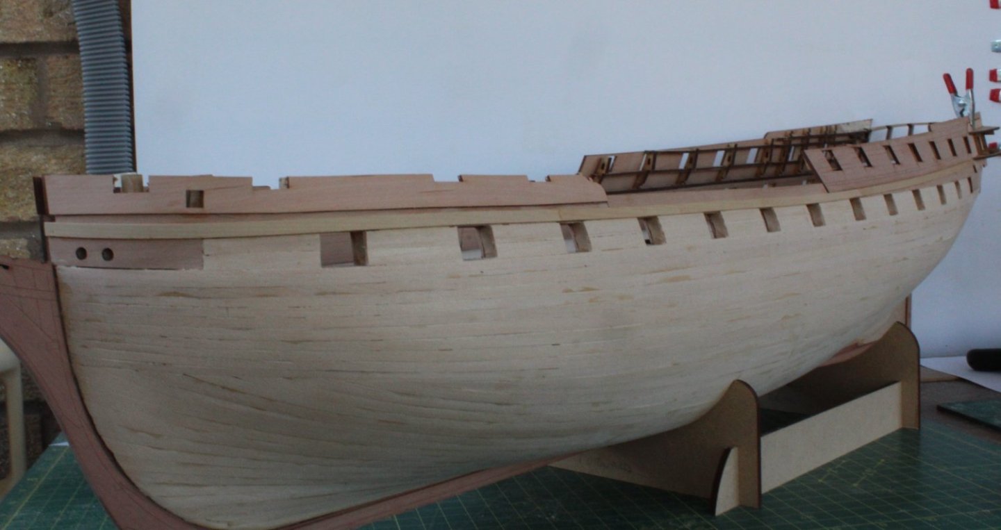
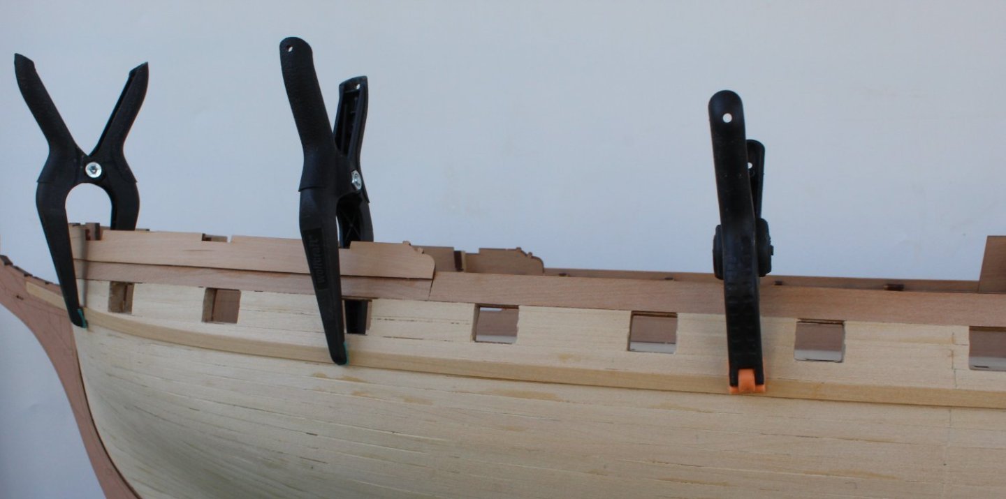
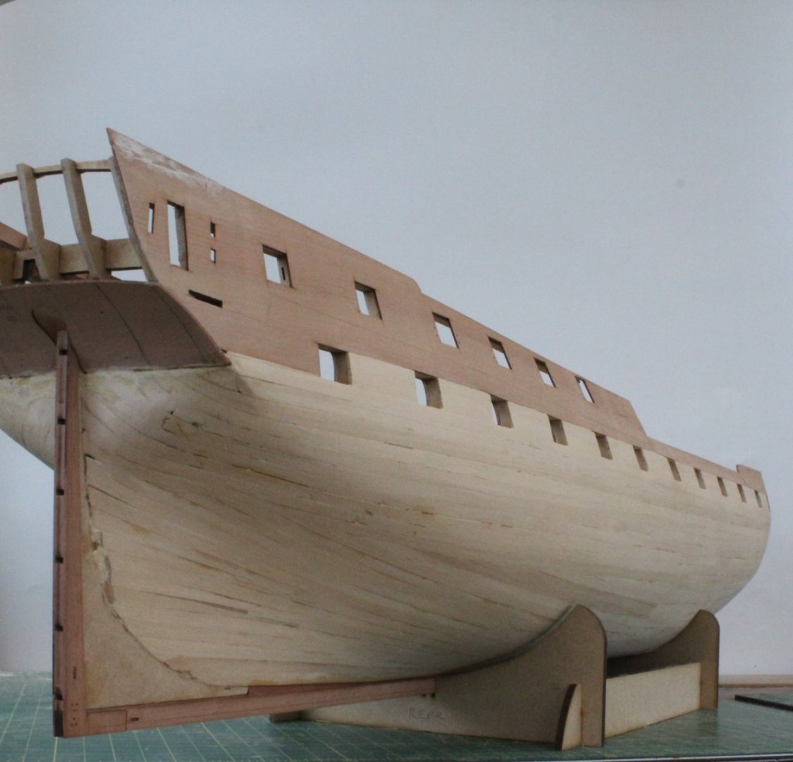
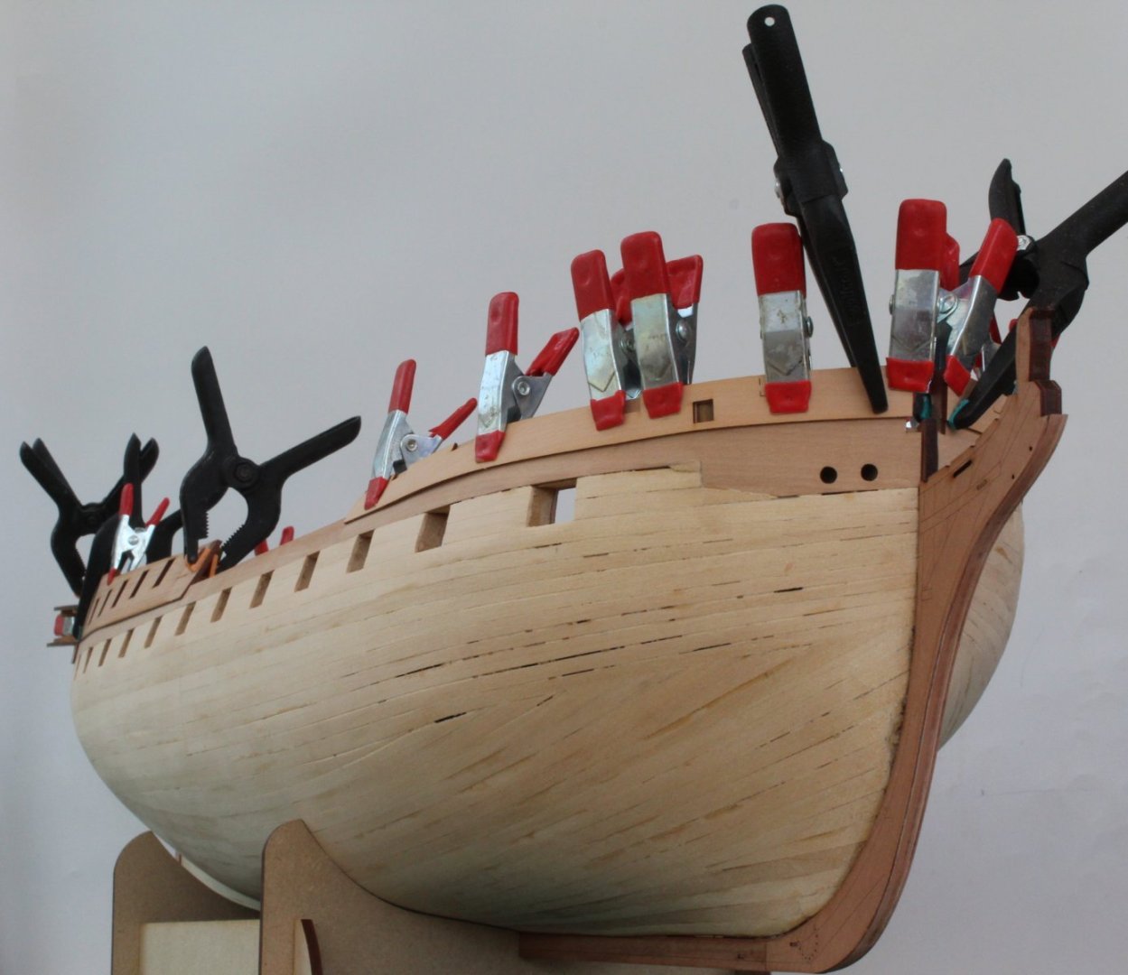
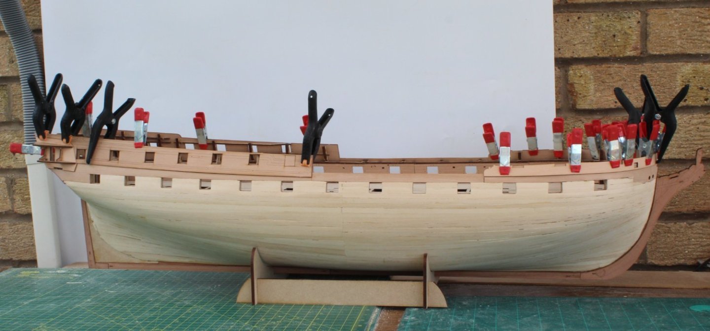
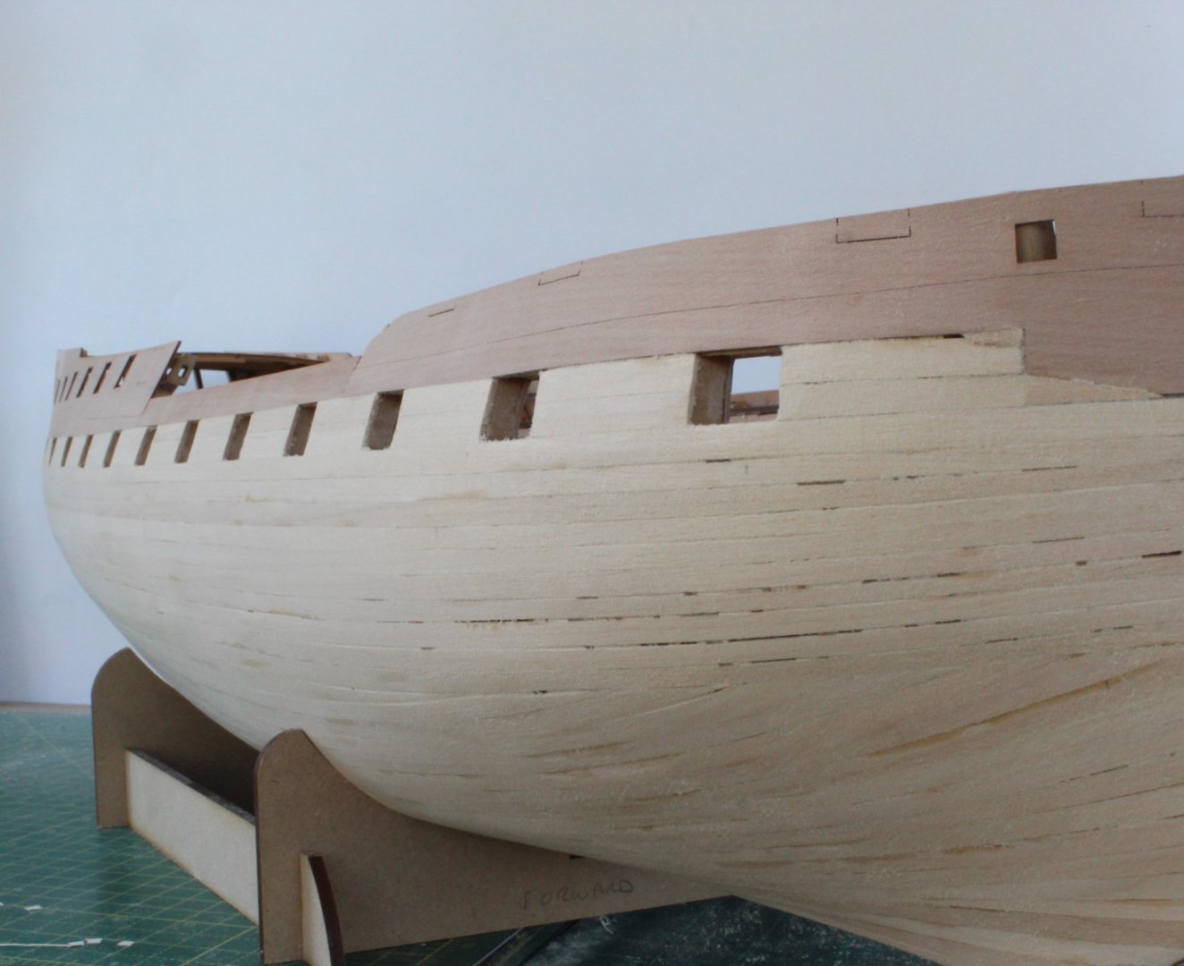
Second Planking – Very slow but steady progress The second planking is proving to be a task that requires a great deal of patience. I have completed the planking from midships to under the transom on the left-hand side. I have not made a brilliant job of it but it is much better that any of my previous models. I have removed the excess planking material from the left-hand side gunport openings, noting the opening still require sanding to get a nice smooth finish. I should have taken more care when selecting the planks as there is quite a bit of colour difference with the boxwood planks. However as the area above the waterline will probably be filled and painted black and yellow it is not really an issue for me. The bow planks are a good fit in the stem rabbet. I have now started to taper the planks complete with a lateral edge bend which is slowing the progress down somewhat. The next plank to be fitted is currently having the lateral edge bend applied.


- 587 replies
-
- 8
-
-
- Indefatigable
- Vanguard Models
- (and 1 more)
-
Looks good. What plank lengths are you using for the 4 butt shift pattern?
- 443 replies
-
- 4
-
-
- Indefatigable
- Vanguard Models
- (and 1 more)
-
Hello Kevin I agree we all make mistakes, me more than most. I'm certainly not rushing this task. Today I added two planks of infill and one plank below the main wale plank. Admittedly it took me quite a bit of time to shape the tapered bow and stern infill planks for a nice tight fit.
- 587 replies
-
- 2
-
-
- Indefatigable
- Vanguard Models
- (and 1 more)
-
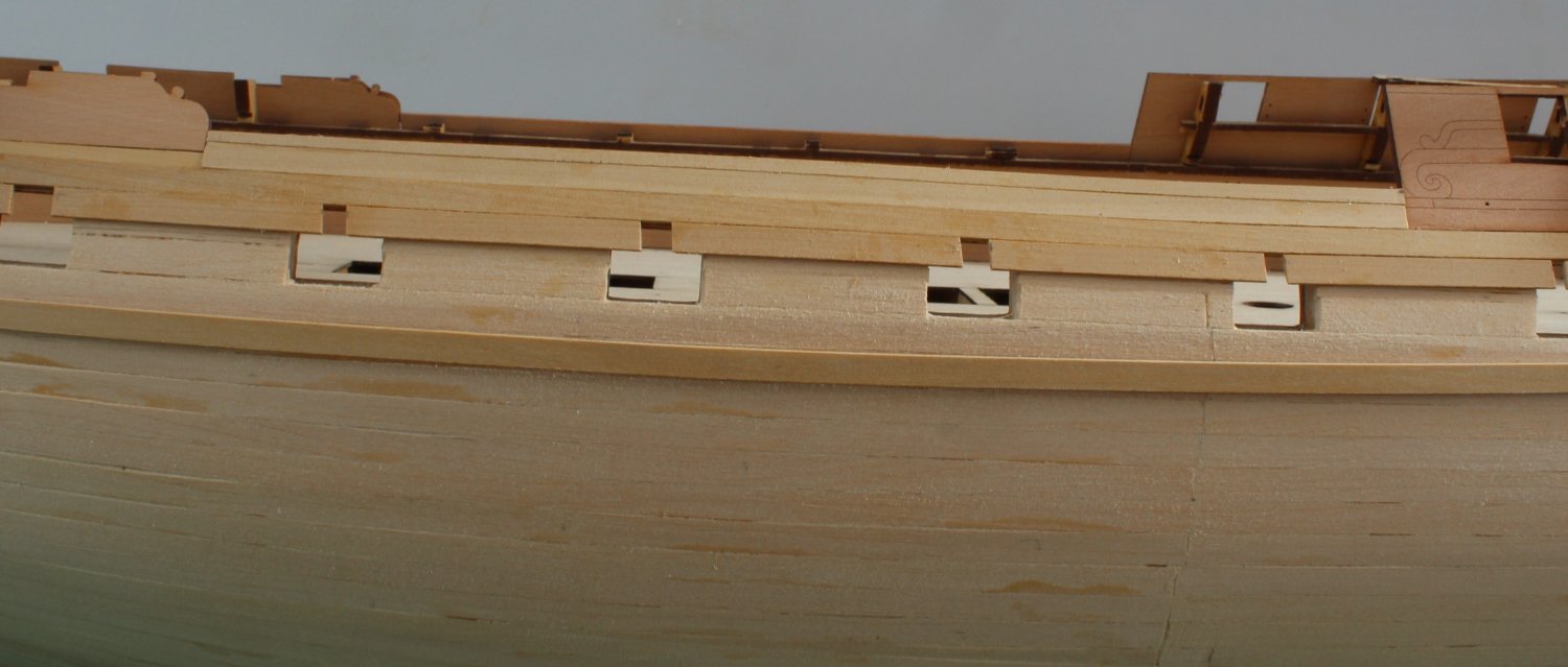
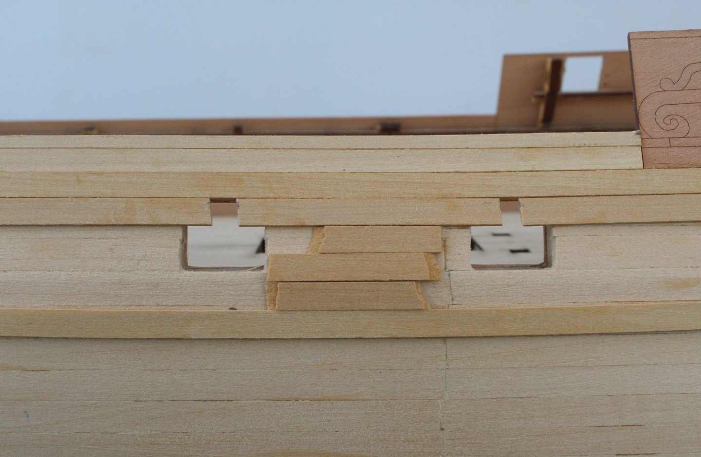
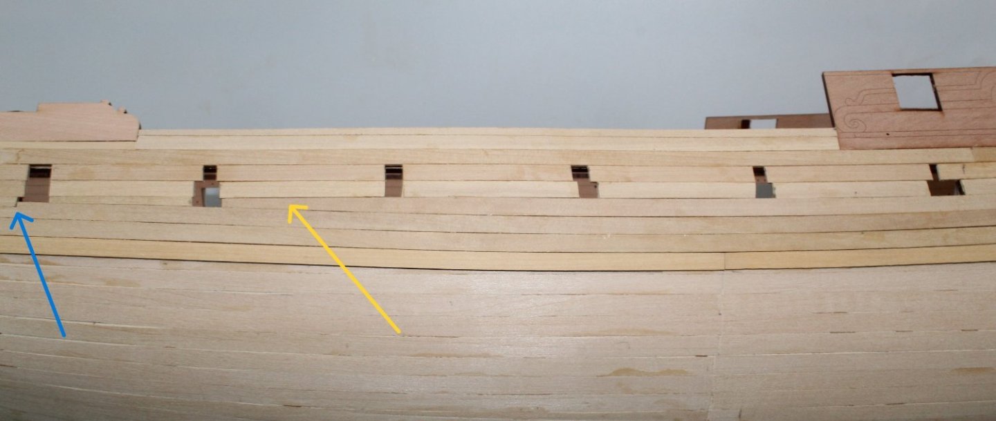
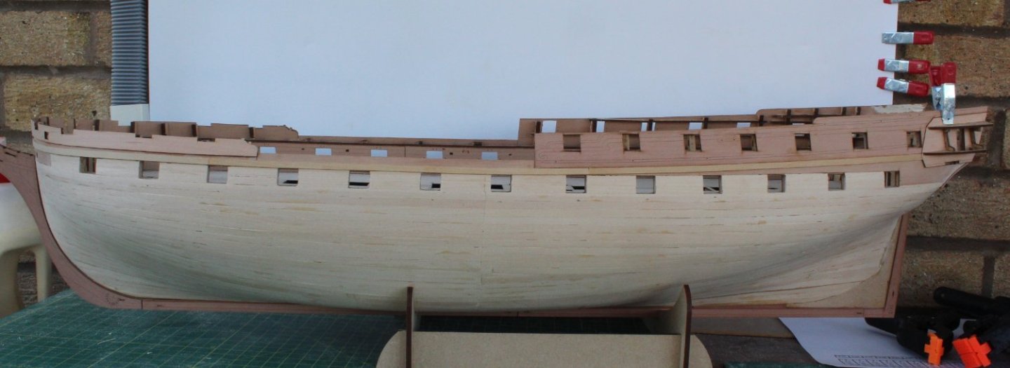
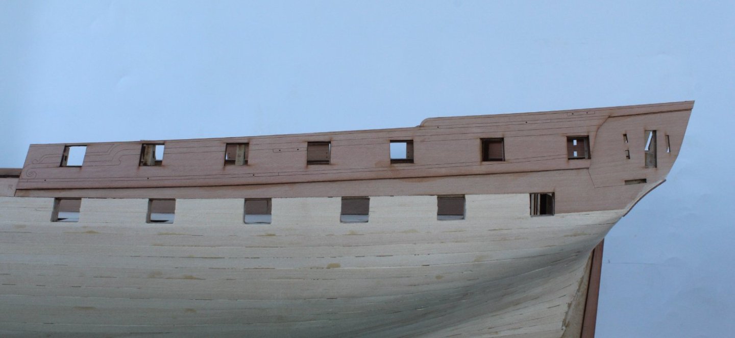
Second Planking In Slow Progress I am really taking my time with this planking. That said I have already made a couple of schoolboy errors when planking over the gun ports. Thankfully this area will be sanded smooth and painted so no harm done. When positioning the plank which will located beneath the main wale I was pleased to note the midship infill area would be 3 planks wide. I was able to use Titebond 111 for the first few plank but resorted to using ca glue for the plank positioned under the main wale plank. I was happy that the lower edge of the lowest plank aligned with the lower edge of the stern counter. The midship area is shown in the next photo, noting the planks require a taper toward the bow (yellow arrow) and a planking error (blue arrow) where I cut the plank beneath the area under the gunport opening. I did add a steeler to offset the taper beneath the gunports in the photo below Although I was being careful I have noted a couple of areas where the planks are not quite sitting flush with each other as can be seen in the photo below. This can be sorted out with a bit of sanding (or filling) before the paint is applied

- 587 replies
-
- 11
-
-
- Indefatigable
- Vanguard Models
- (and 1 more)
-
Thank you. I am going very slow and steady for the second planking.
- 587 replies
-
- 1
-
-
- Indefatigable
- Vanguard Models
- (and 1 more)
-
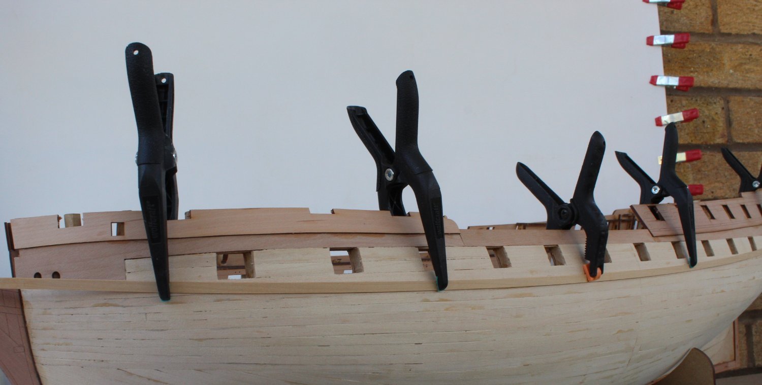
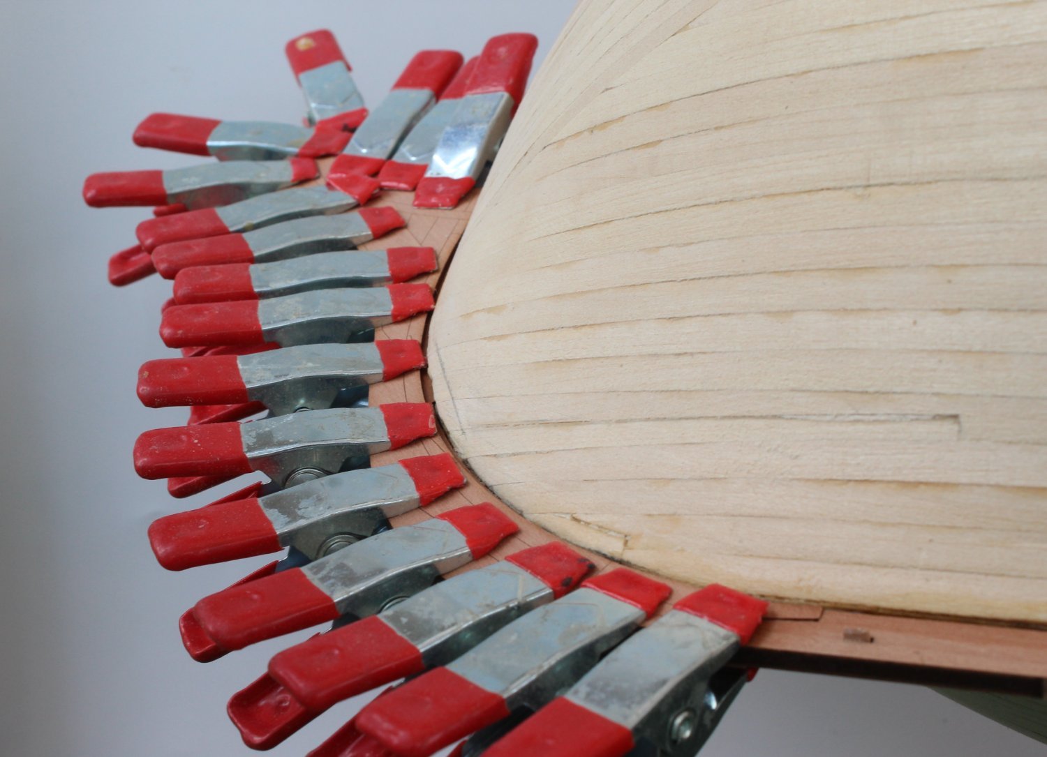
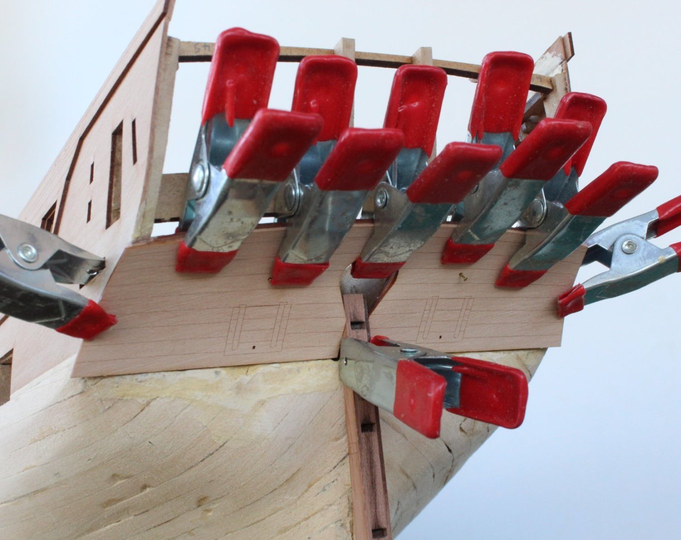
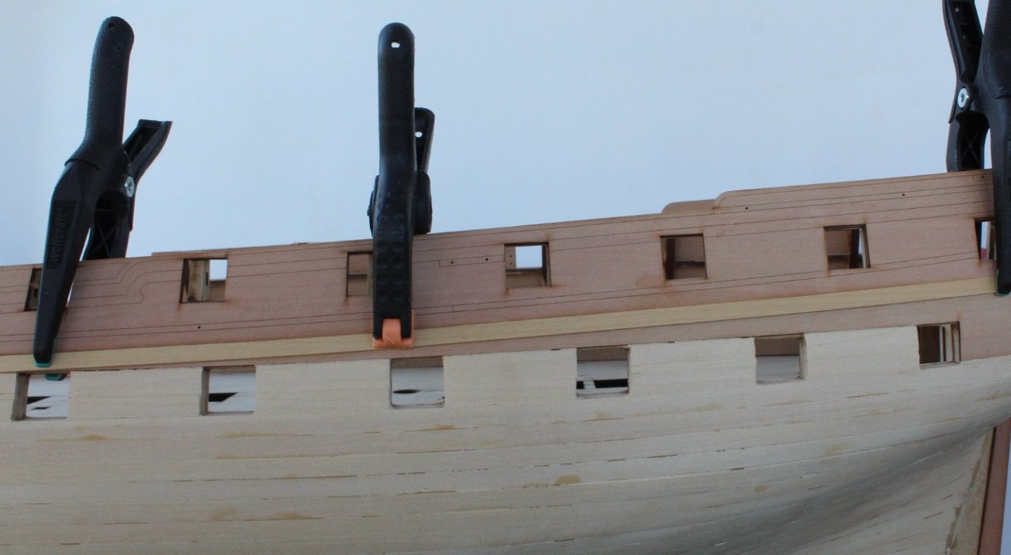
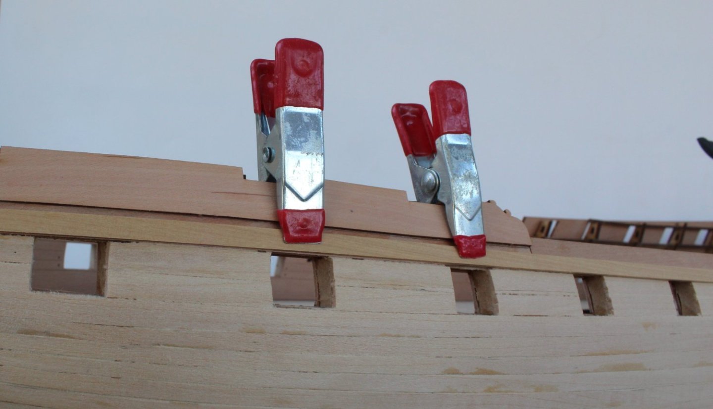
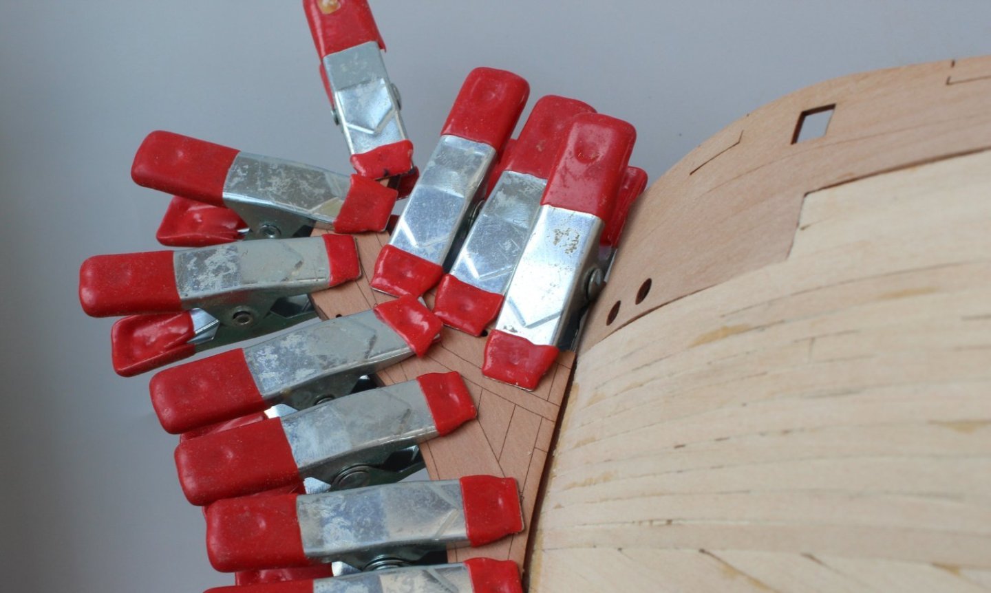
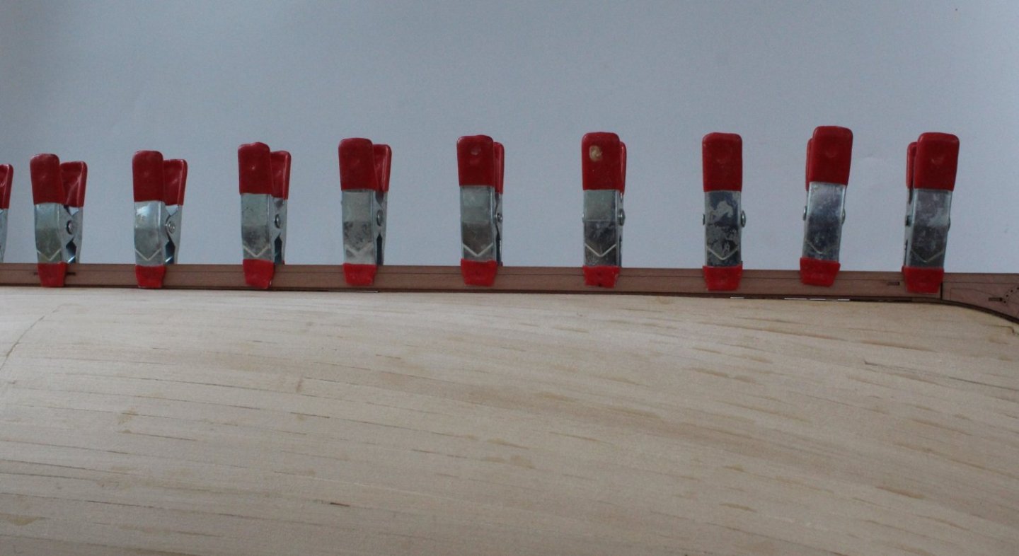
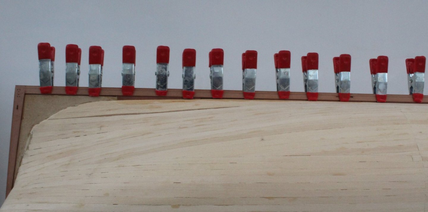
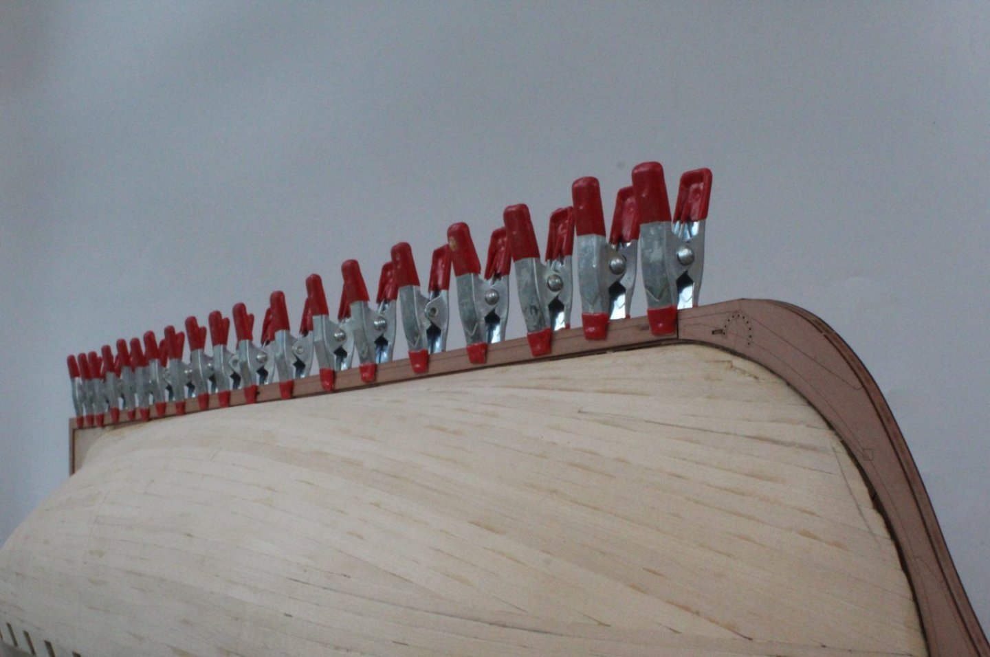
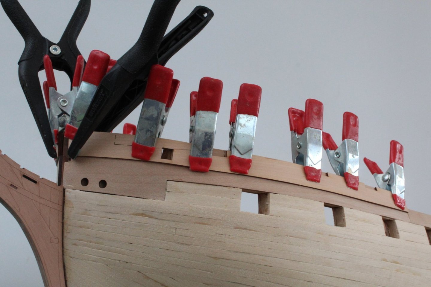
Start Of Second Planking I have taken the plunge and started the second planking. I am taking my time with this process and making sure I am really happy with each plank fit before adding the glue. As per the instructions I started with the plank that sits below the outer bulwark patterns. I used Titebond III and a series of clamps for the first plank. I will probably resort to ca glue for the lower planks. I have added the first two planks and also planked in the area between the bow and stern outer bulwark patterns. The next plank to be added will the one which will be used to indicate the position of the main wale. The plank has been soaked in water and clamped to the hull and will be left to dry overnight.

- 587 replies
-
- 8
-
-
-
- Indefatigable
- Vanguard Models
- (and 1 more)
-
Amati Planking Clamp Set A7377 | Cornwall Model Boats
- 648 replies
-
- 5
-
-
- Indefatigable
- Vanguard Models
- (and 1 more)
-
The instructions were easy to understand and implement. Many thanks.
- 587 replies
-
- 2
-
-
- Indefatigable
- Vanguard Models
- (and 1 more)
-
Thanks Kevin I am just summing up the courage to start with the second planking. Glenn (UK)
- 443 replies
-
- 4
-
-
- Indefatigable
- Vanguard Models
- (and 1 more)
-
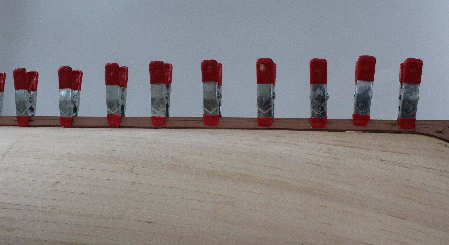
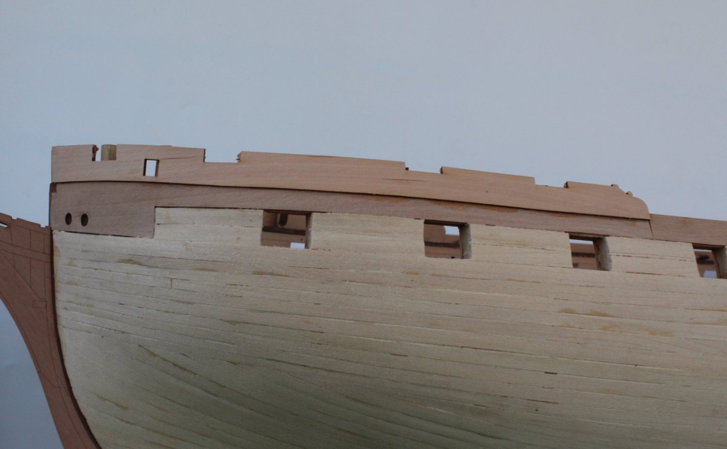
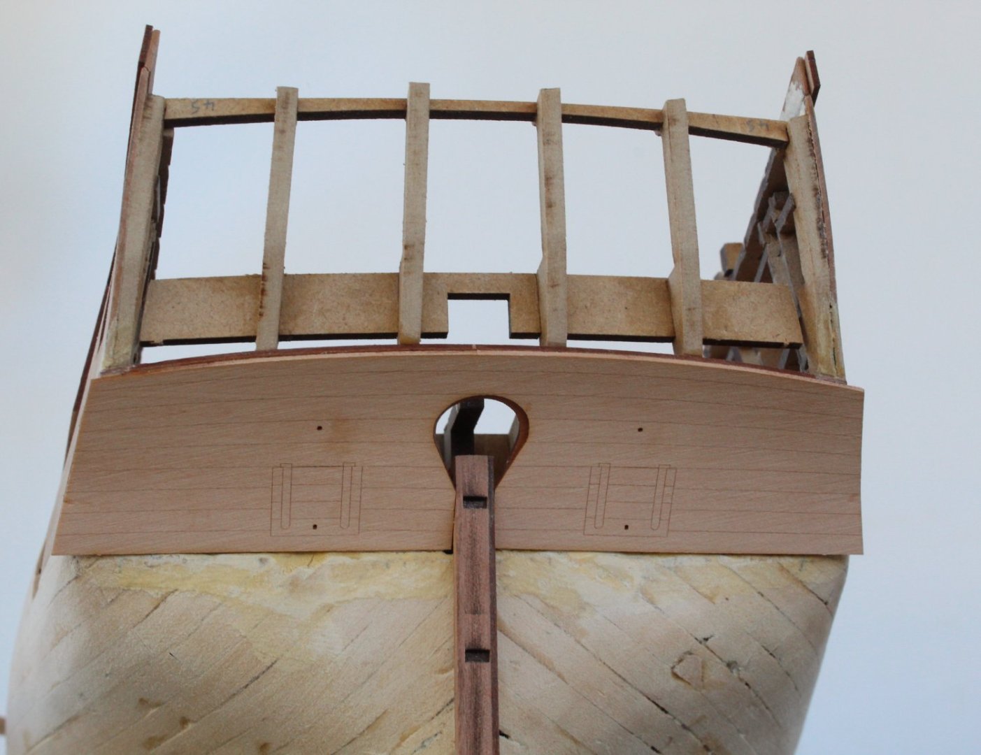
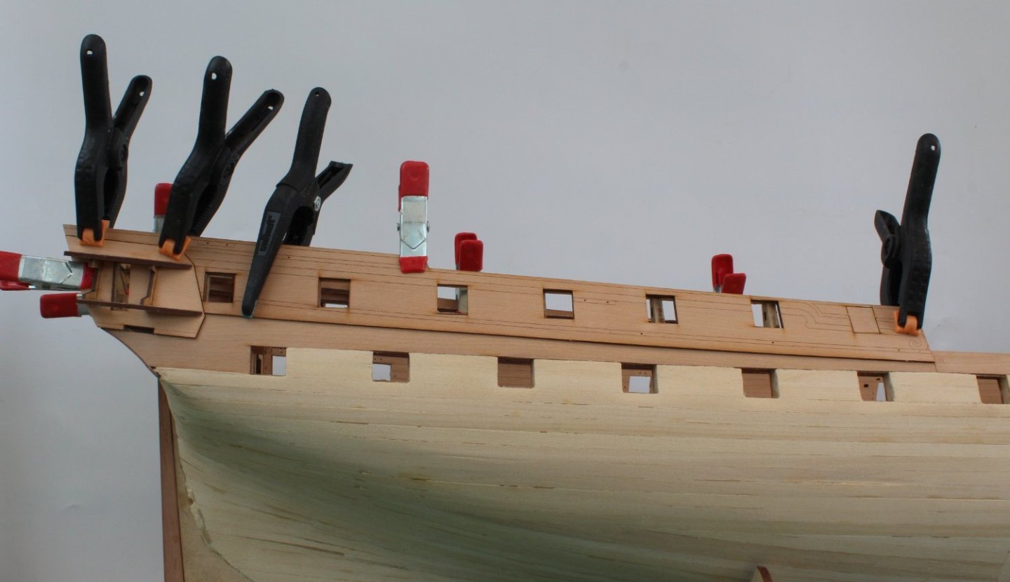
Second Plank Position for Main Wale Following on my my last post regarding the position of the main wale I have made a test fit of the plank after adding a series of dots to indicate the planks position.

- 587 replies
-
- 13
-
-
- Indefatigable
- Vanguard Models
- (and 1 more)
-
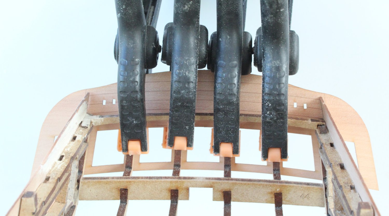
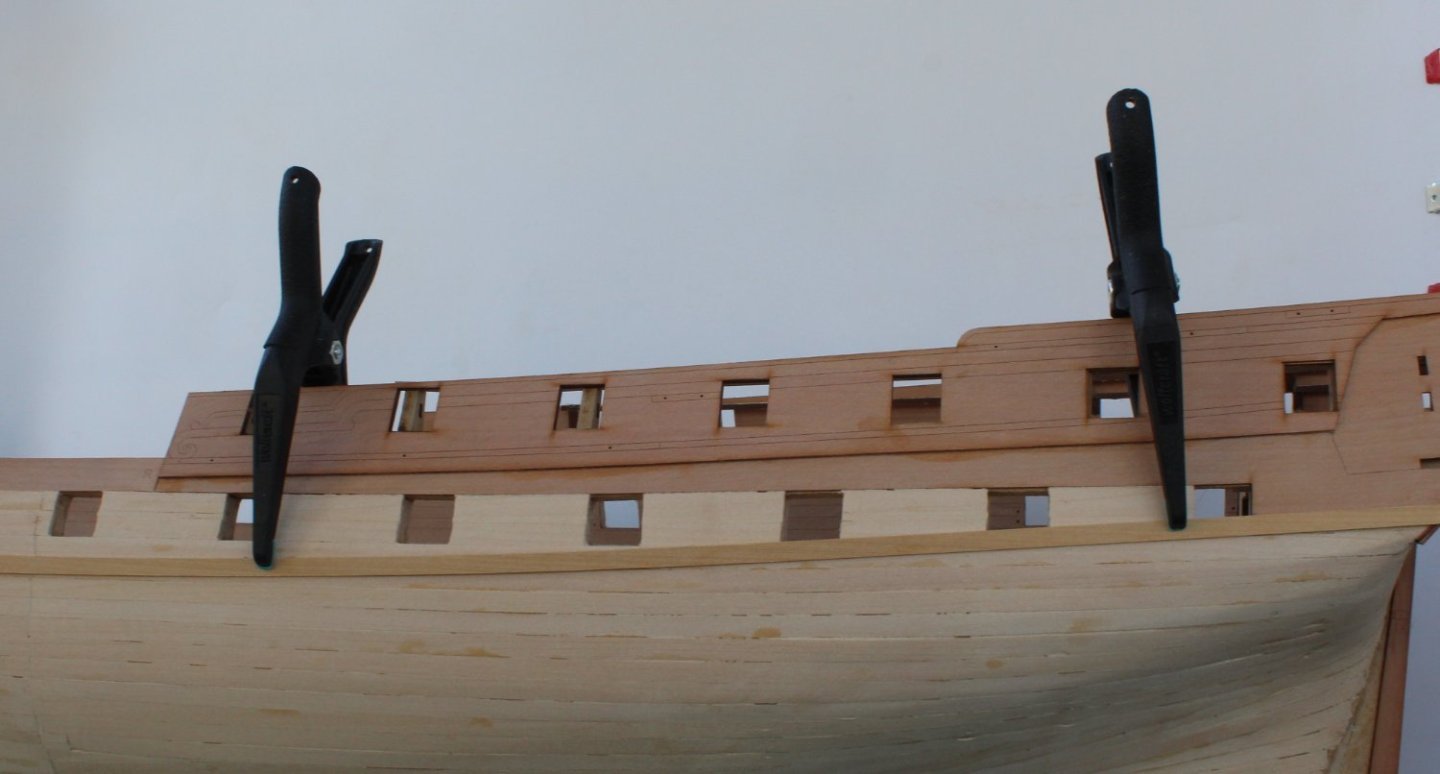
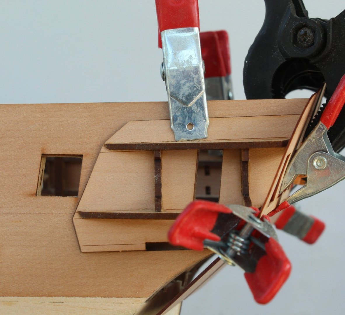
Outer Bulwark Patterns and Lower Stern Counter With the outer bulwark patterns clamped in place I drew a pencil line along the bottom edge. I then removed the outer bulwark patterns and brushed Titebond III to the hull, using the pencil line as a guide. Each pattern was glued and clamped to the hull in turn. I did consider following Kevin’s lead and using boxwood to plank the lower stern counter. However, as I do plan to paint the upper section of the hull and noted the stern counter would be painted black. Based on this I decided to add the kit supplied outer lower stern counter pattern. I brushed Titebond III to the inner lower stern counter pattern and then outer pattern was carefully aligned, using pins to line up through the holes. A series of clamps were then used to hold the pattern is place. Turning my attention to the start of the second planking the requirement is to add the first and second planks, one after the other, directly underneath the outer pear bulwarks. When I test fitted the first plank I noted that the natural run meant it would not sit flush with the underside of the bow outer bulwark pattern. I noted this was also the case with the prototype when looking through Jim’s and Kevin’s build log and the photos in the build manual. With regards to the second planking one key plank must be fitted as a guide for the main wale, when it is added. A series of dots need to be added to indicate where this plank needs to be laid. The position of these dots is taken from measurement from plan sheet 6. Once the dots have been added a plank will then be added along the underside of those marks. This plank should also align with the top of the prow when fitted correctly.
- 587 replies
-
- 7
-
-
- Indefatigable
- Vanguard Models
- (and 1 more)
-
Hello Kevin Great work on your boxwood planking. I am about to start mine today and I have a couple of questions. Did you use ca or wood glue for the second planking? I noted in the build manual that Jim used Titebond wood glue for all second planking on the prototype. I am not how to get the second layer of planks to stay in contact with the hull as the glue starts to cure and grip without using pins. My current thinking, once I am happy the plank is ready to be added, is to apply some ca to the hull and to spray the planks with an activator before fitting. Did you use any lateral plank bends when adding the planks around the bow area? I noted you thought you started to taper to early. My initial thought will be to plank downward until I need to start to taper and then to divide the hull into bands for the the rest of the planking. I did find adding Chuck's lateral bending method to the planks on my first planking paid dividends around the bow area. Keep up the good work and informative build log. Thanks Glenn (UK)
- 443 replies
-
- 6
-
-
- Indefatigable
- Vanguard Models
- (and 1 more)
-
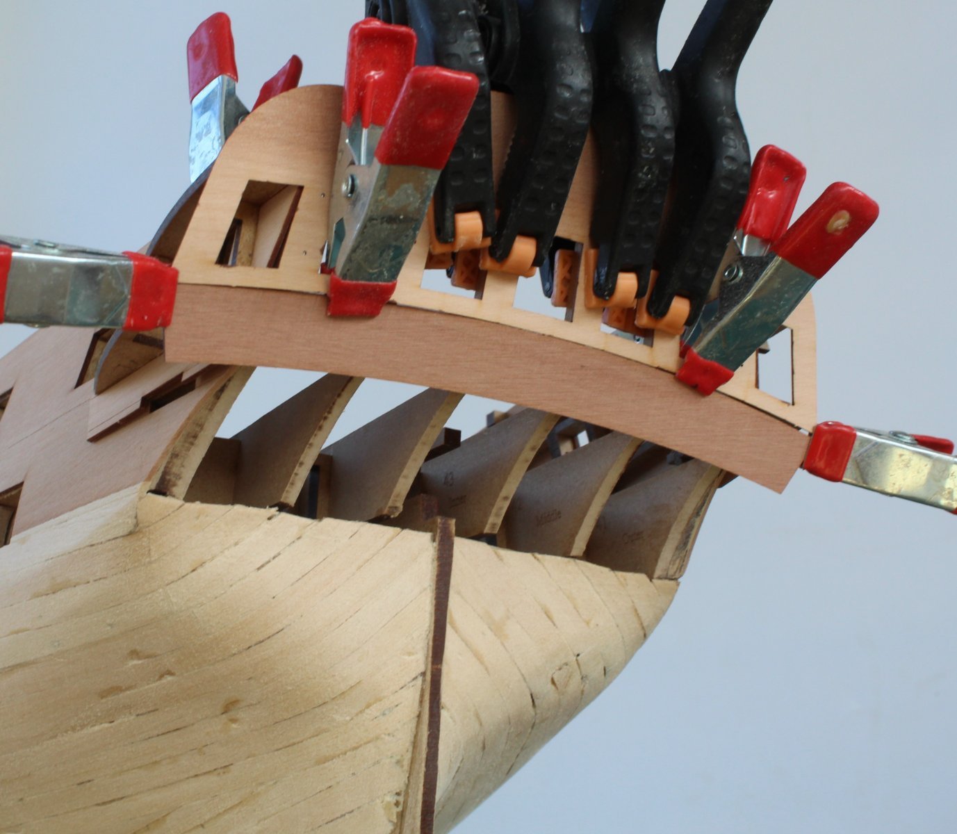
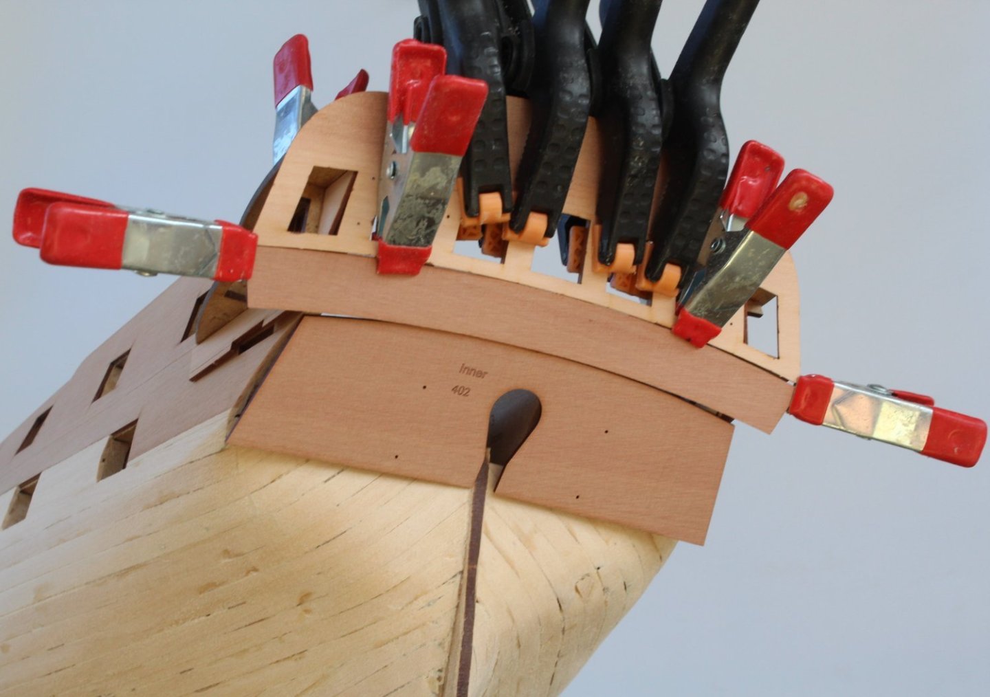
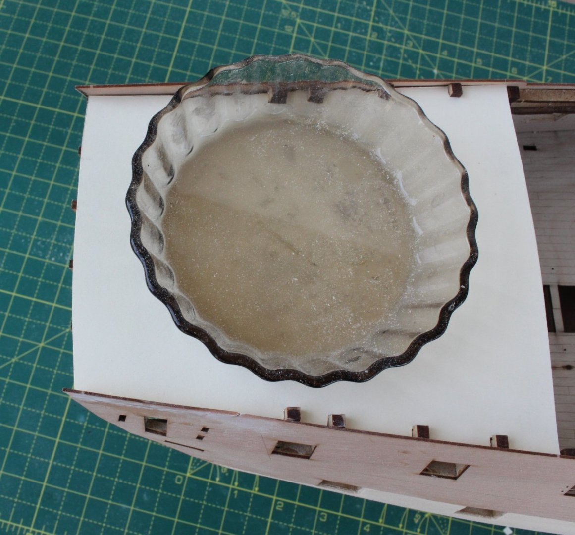
Preparation Work For Second Planking Following on from my last post the lower stern counter pattern was soaked in hot water for 30 minutes and then clamped to my plastic 2 pint measuring jug so the required bend could be applied. Once the pattern had been left for over 12 hours the stern counter pattern was glued in place. The outer patterns were glued and clamped to the stern post and whilst the glue was curing the prow and two keel patterns were then glued to the hull assembly. Once the stern post assembly glue had been given time set it was glued to hull. There are outer patterns to be fitted to the prow and keel. I brushed glue to the prow and keel and then, using the alignment pegs, the outer patterns were added. You can never use to many clamps. With the clamps removed the Indy is now ready for the next phase of the build process which will be the start of the second planking The first task for the second planking is to add the outer bulwark patterns (bow and stern). I have dry fitted the parts to check the fit and alignment. Everything looks good so when I next return to the shipyard I will glue outer bulwark patterns to the hull. I noted that Kevin used boxwood to plank the lower stern counter pattern rather than using the kit supplied pear pattern. I might follow suit.

- 587 replies
-
- 7
-
-
- Indefatigable
- Vanguard Models
- (and 1 more)
-
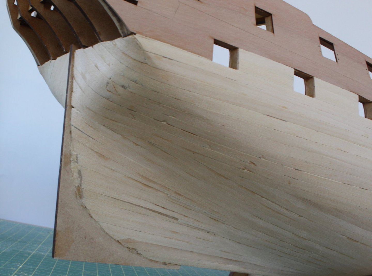
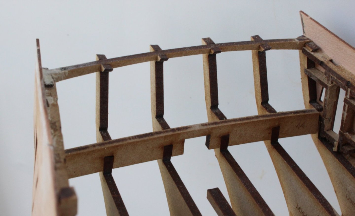
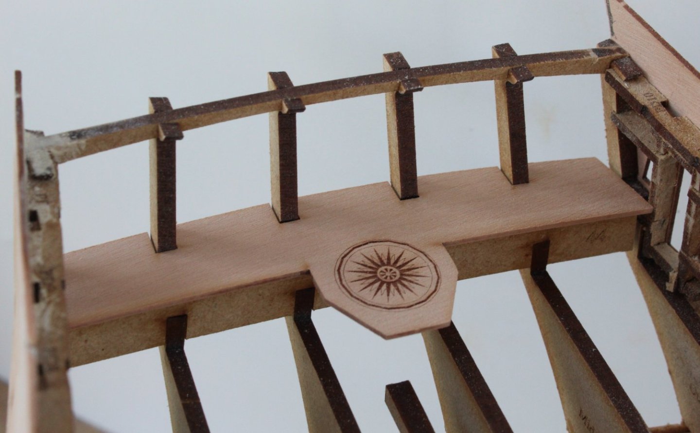
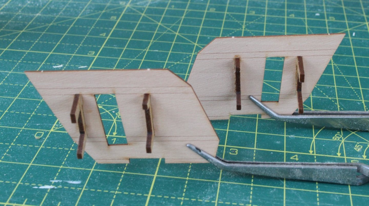
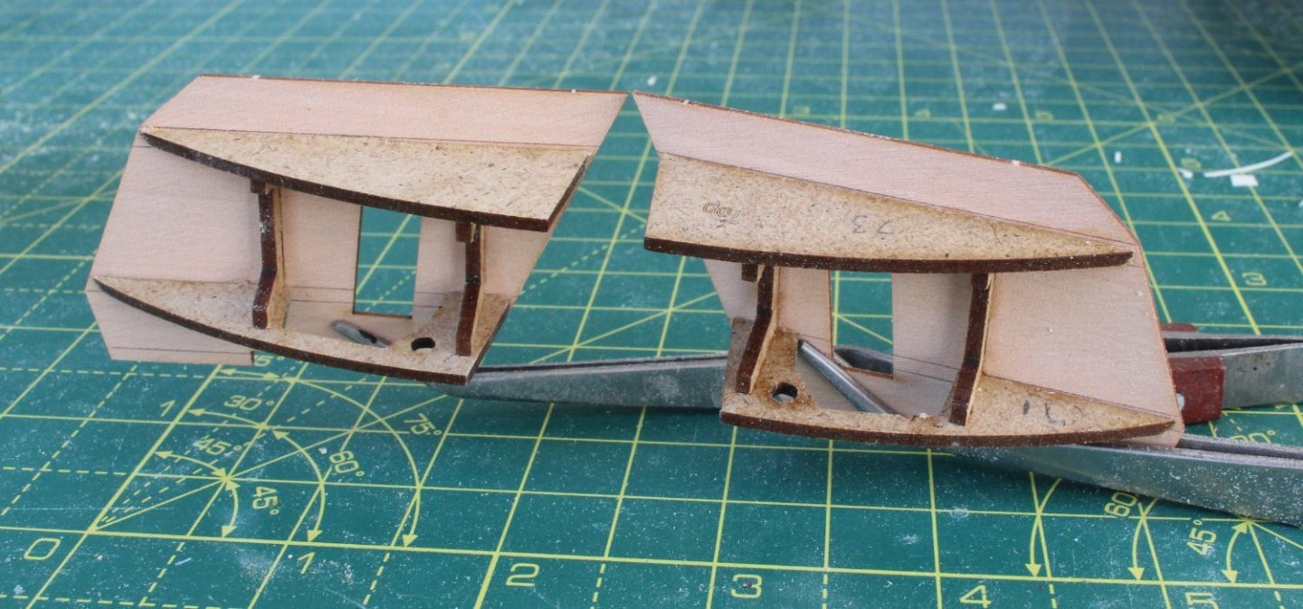
Preparation Work – Stern Area I have now sanded the hull (1st planking) to a nice smooth finish. Before moving on to adding the 2nd planking there is a bit of preparation work such as fitting the lower stern counter. The first task was to glue the tiller bulkhead in place. Next the rudder casing top canopy part was dry fitted. As the rear face did extend past the stern frames it was necessary to sand it flush. I made a carboard template of the poop deck and when test fitted the back edge did not extend past the stern frame so there was no need to sand the back edge of the actual poop deck pattern. Next it was time to start to assemble the quarter galleries. The first task was to glue the two quarter gallery stool spacers. Before the quarter gallery upper and lower stool patterns can be fitted it is necessary to bevel so they are flush fitting with the quarter gallery base pattern. After checking the fit after adding a bevel the quarter gallery upper and lower stool patterns were glued in place. The back of the stern frame patterns has been sanded to follow the required curve. I did manage to damage the top of the right side bulwark pattern and I had to made and fit a new part. I had to use some wood filler to fill some of the gaps along the joint line. The inner upper stern counter pattern was then positioned. As per the build manual instructions the pattern was set to be approx. 2mm above the top of the bulwarks. The quarter gallery assemblies were clamped to the hull (no glue) and it was necessary to make some minor adjustments to the position of the inner stern pattern assembly. Next the middle stern counter pattern was added. In the photo below I have used some clamps to hold the pattern in place, but this pattern will be pinned in place before the position of the lower stern counter pattern is finalised. Before the lower stern pattern position can be finalised it does need to be soaked in hot water for around 30 minutes and then bent to follow the curve of the stern frames. In the picture below I have done a pre-bend test fit to get an idea of what the completed stern counter assembly would look like.
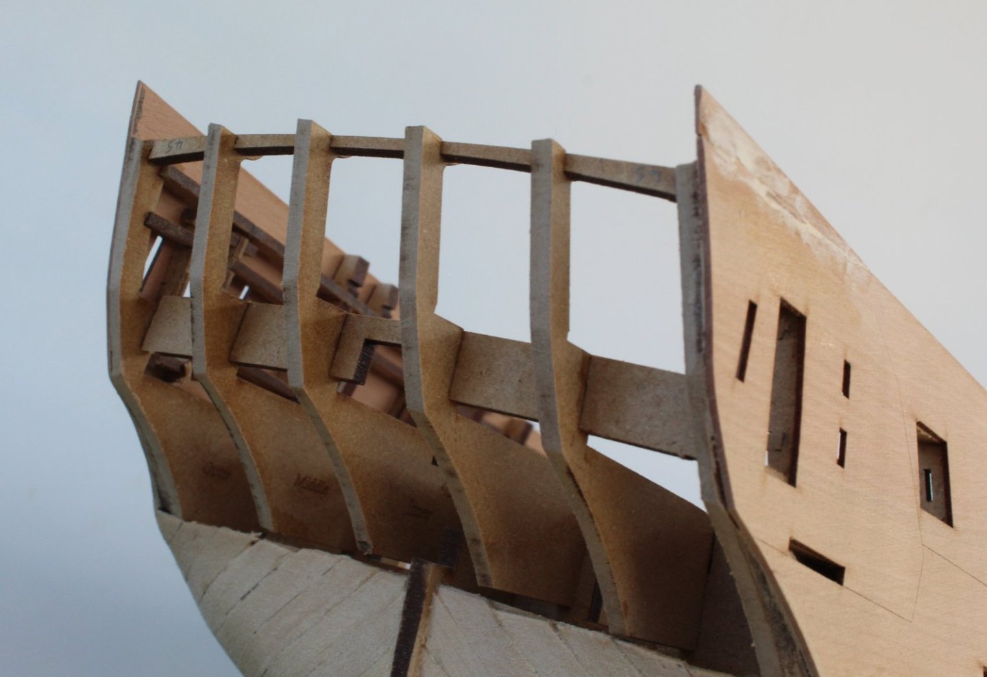


- 587 replies
-
- 10
-
-
-

-
- Indefatigable
- Vanguard Models
- (and 1 more)
-
Your second planking looks good. I have found lateral bending and planking in bands takes a lot more time and effort but the end results justify the means.
- 587 replies
-
- 1
-
-
- Indefatigable
- Vanguard Models
- (and 1 more)
-
Thank you, I will have to excercise greater care and be prepared to take much more time when I start to add the boxwood planking. I will keep an eye on @Kevin 2nd planking progress as he is the current pathfinder for this model.
- 587 replies
-
- 1
-
-
- Indefatigable
- Vanguard Models
- (and 1 more)