Glenn-UK
-
Posts
3,175 -
Joined
-
Last visited
Content Type
Profiles
Forums
Gallery
Events
Everything posted by Glenn-UK
-
 Many thanks. Like most builders I've made mistakes but thankfully they are mostly hidden to the naked eye. I have previously built Speedy, Alert and Duchess of Kingston. I did cut my teeth on building Caldercraft's Victory a few years ago which sadly I never got rigged. I have finally learnt to take my time on this build which has been beneficial.
 -
It certainly where the term "heads" comes from. Throne comes from Louis XIV who would continue to conduct his royal duties whilst sat on the toilet, which became known as the Throne room
- 476 replies
-
- 2
-

-
- sphinx
- vanguard models
- (and 1 more)
-
Many thanks. There are a few bits I wish I had done better but overall I am pleased with this build so far.
- 476 replies
-
- 2
-
-
- sphinx
- vanguard models
- (and 1 more)
-
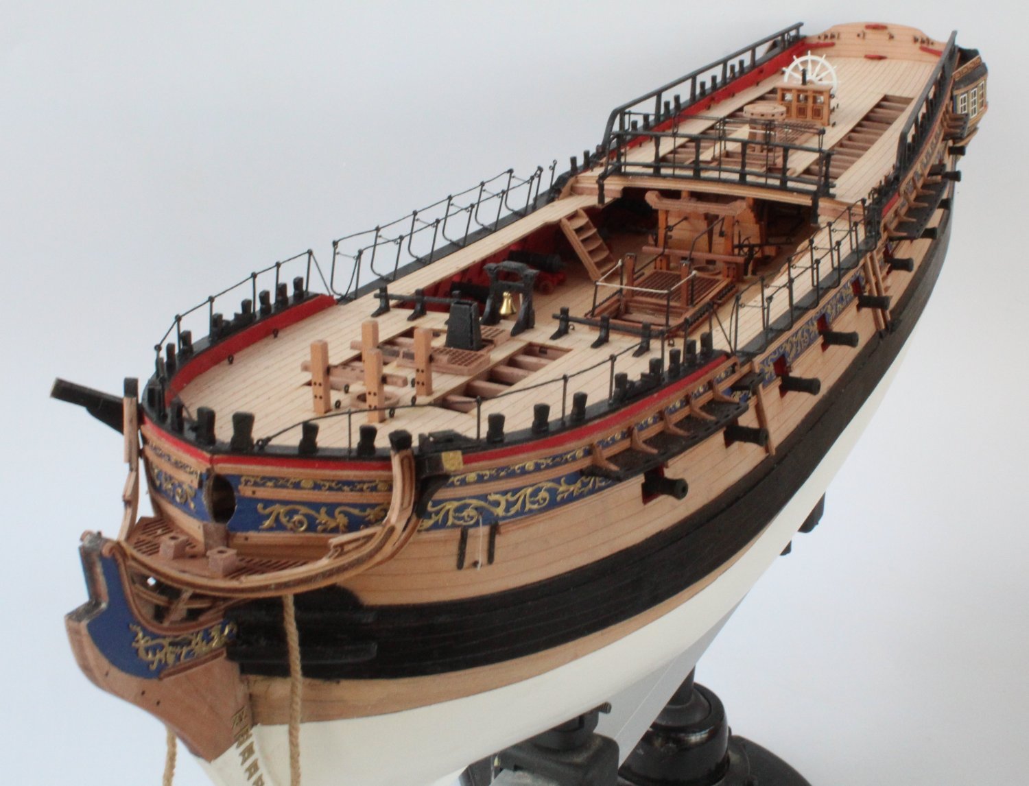
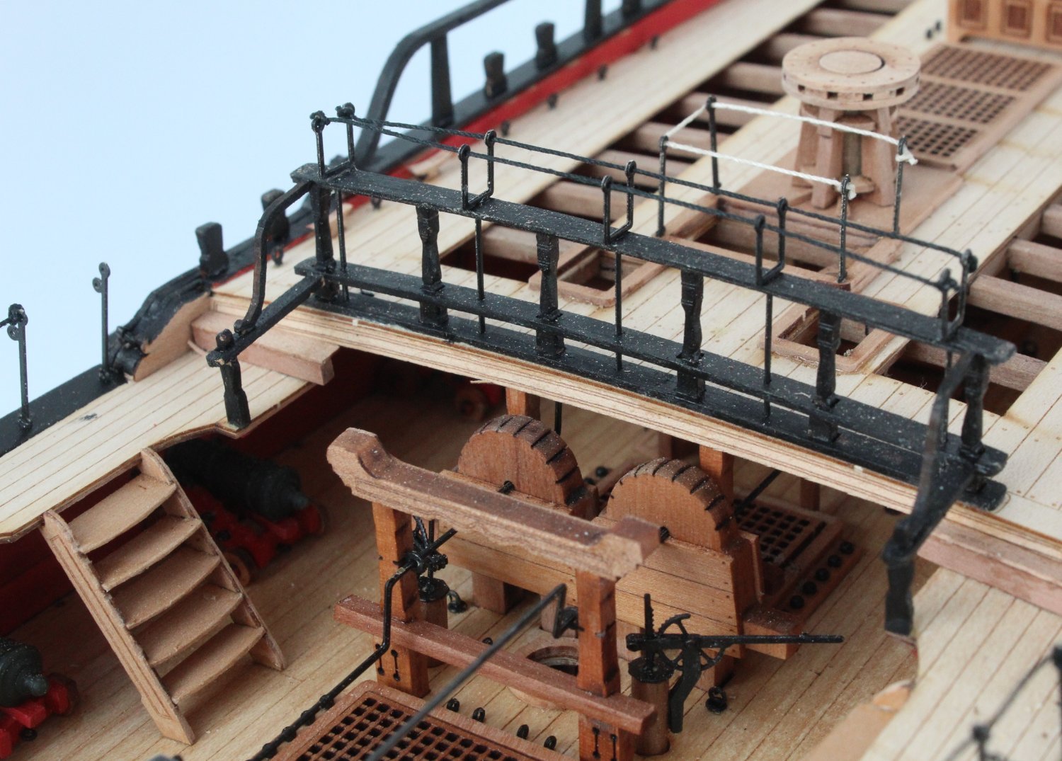
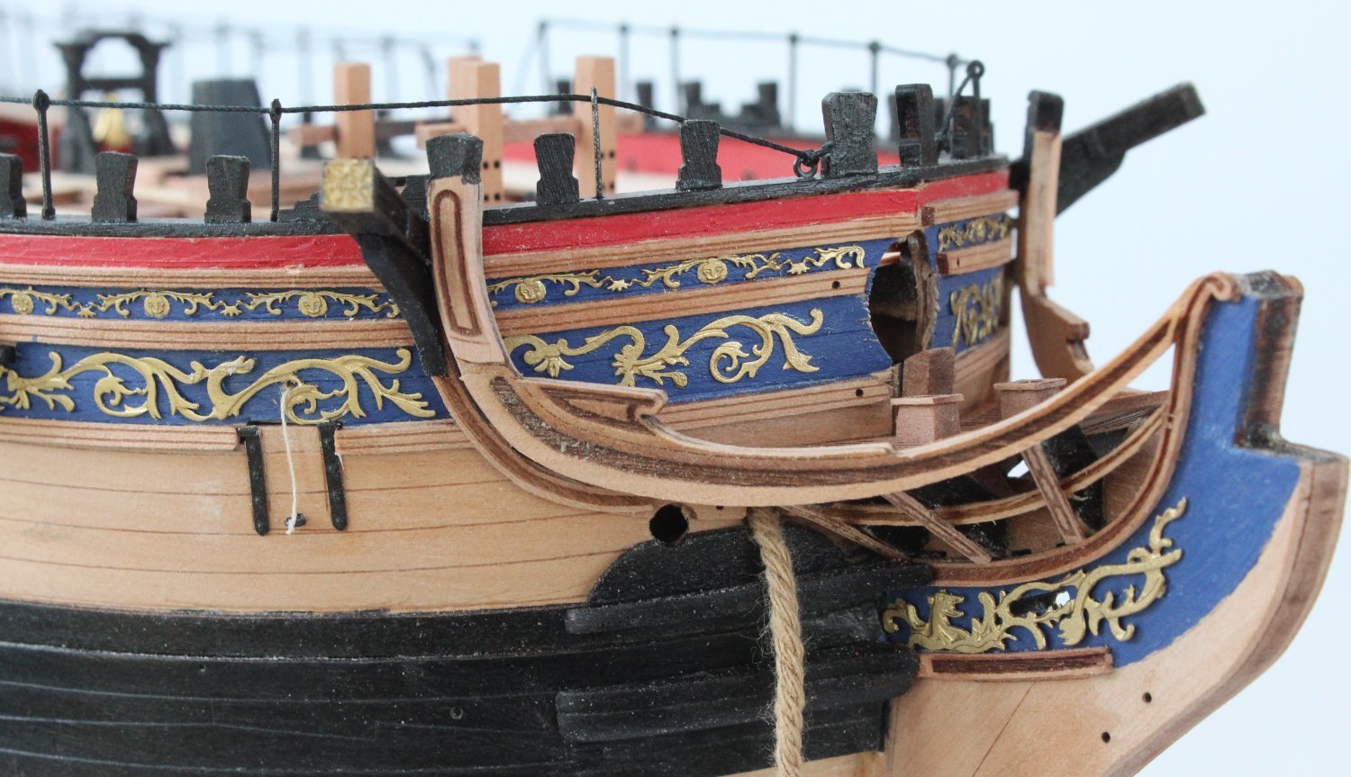
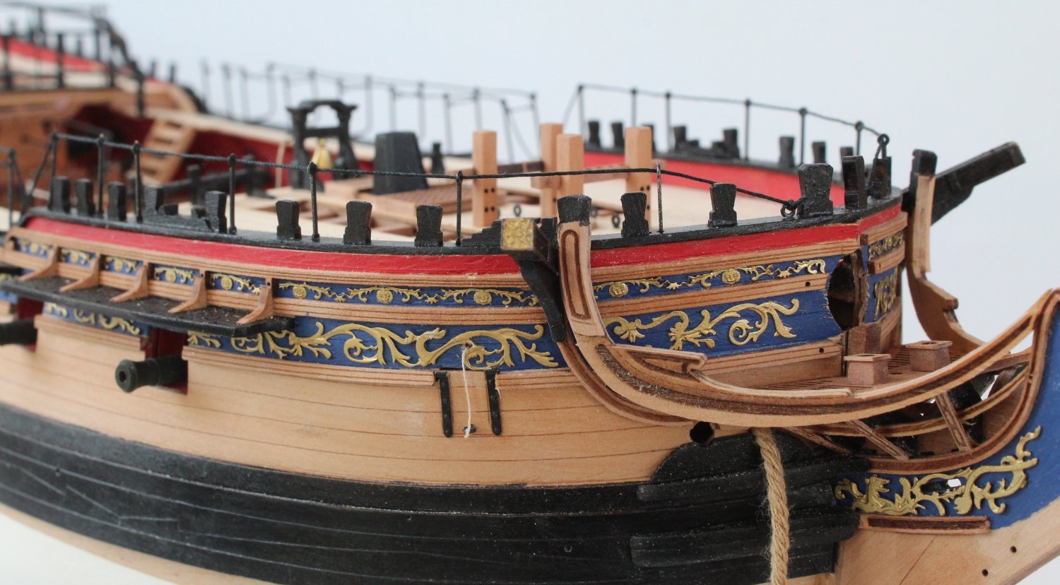
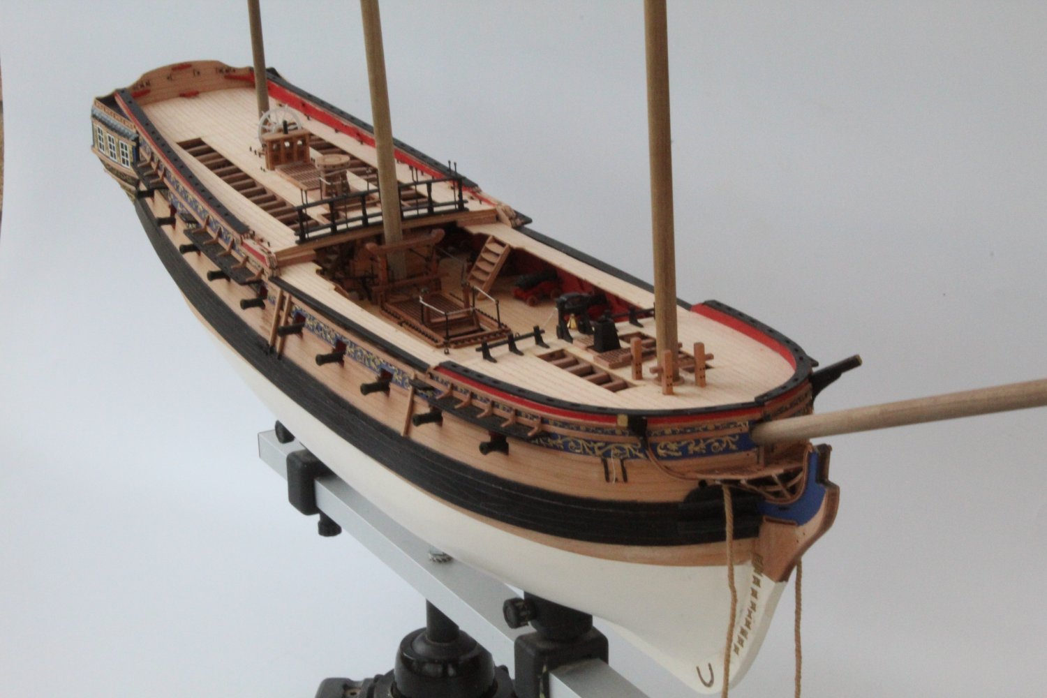
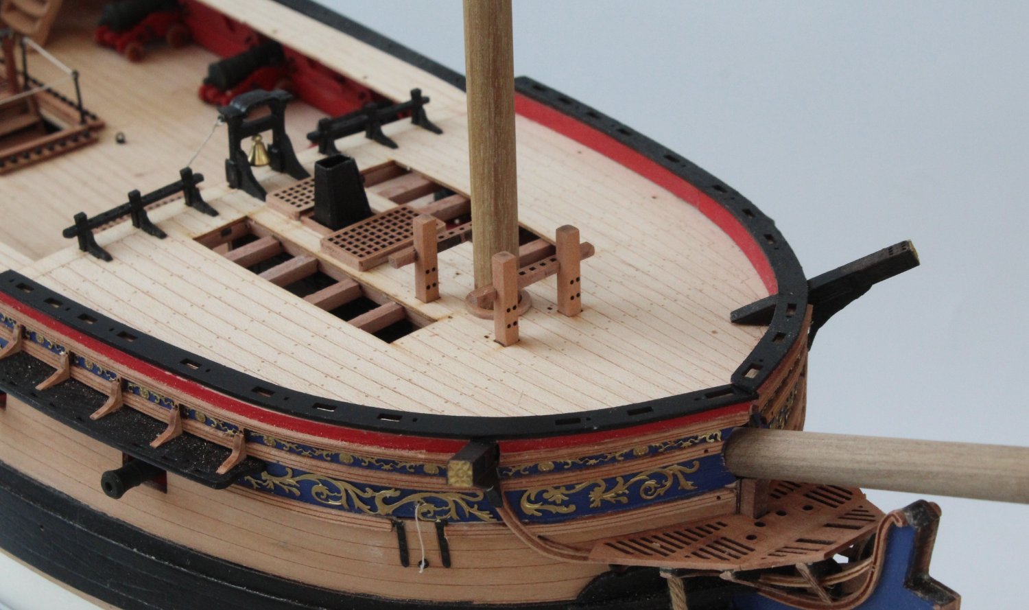
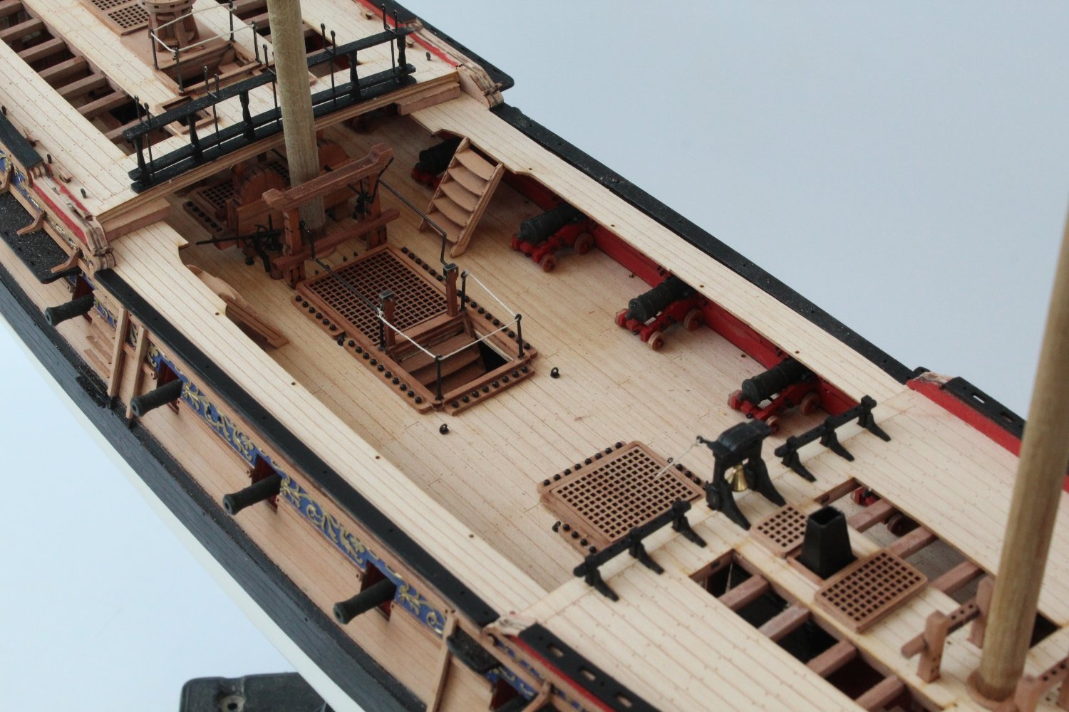
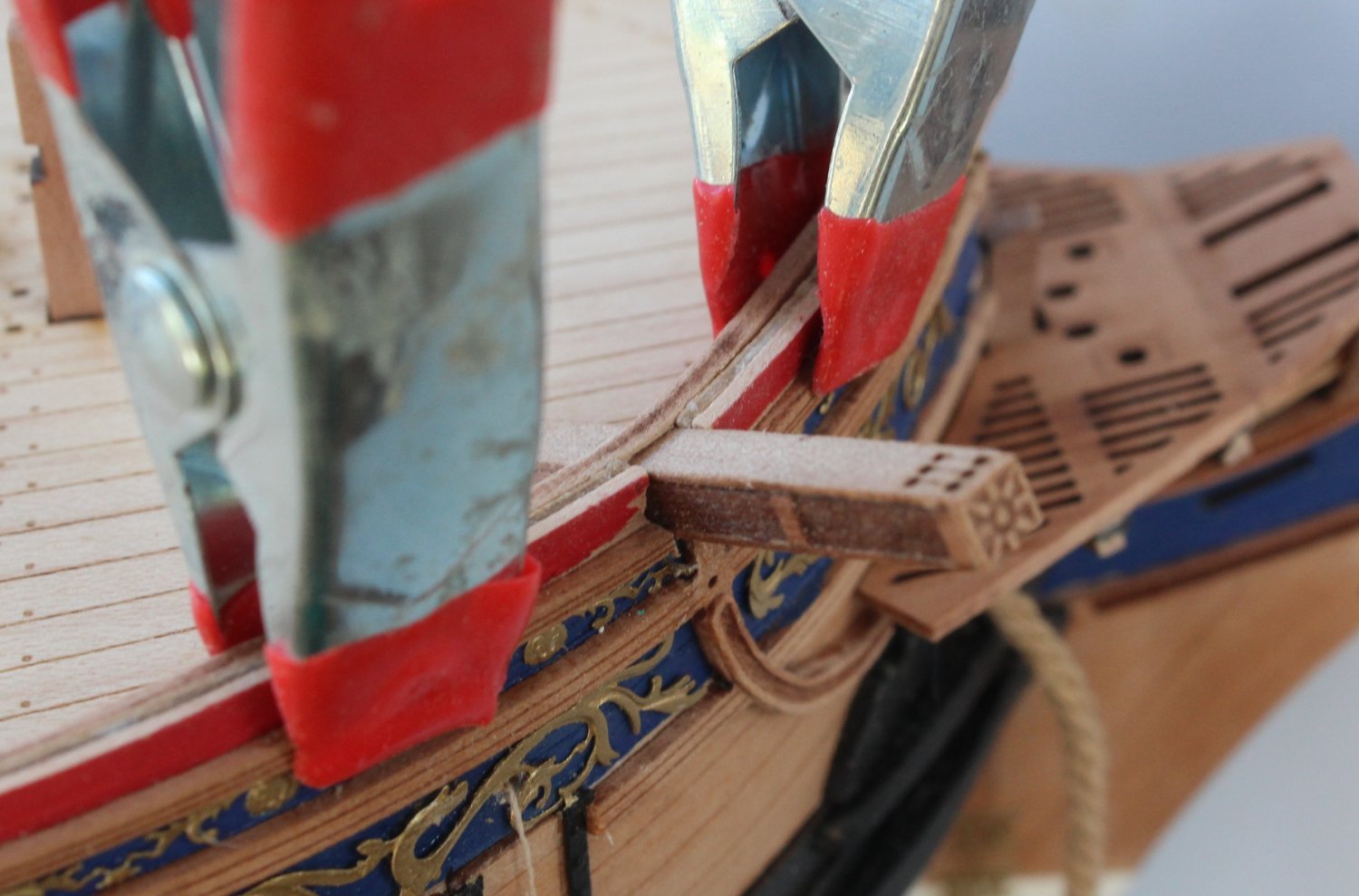
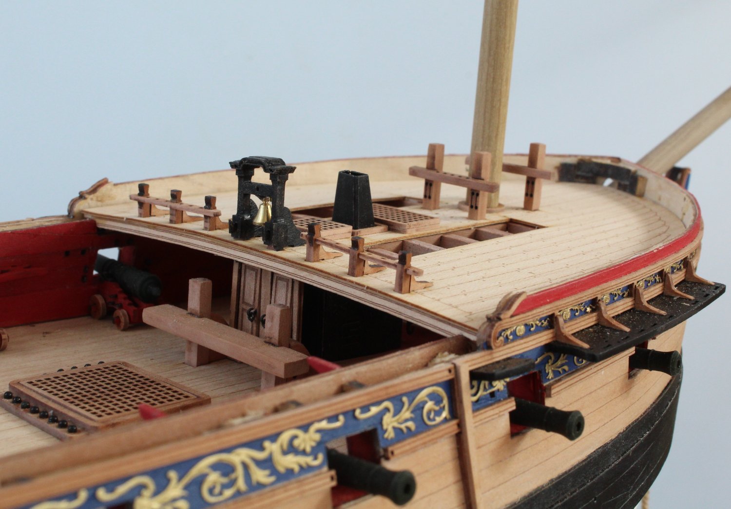
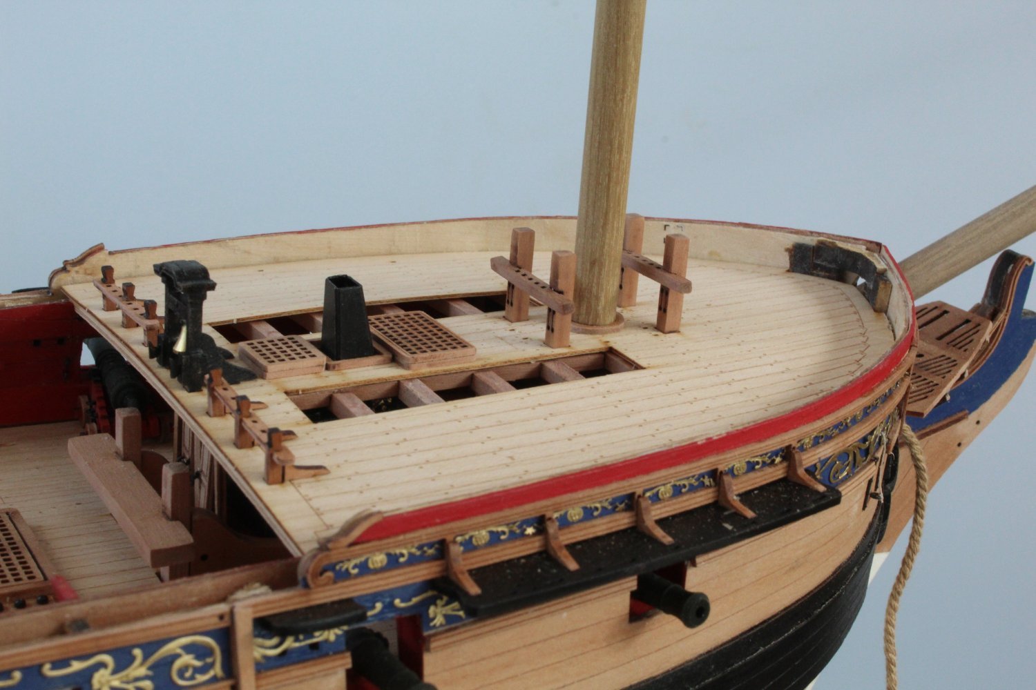
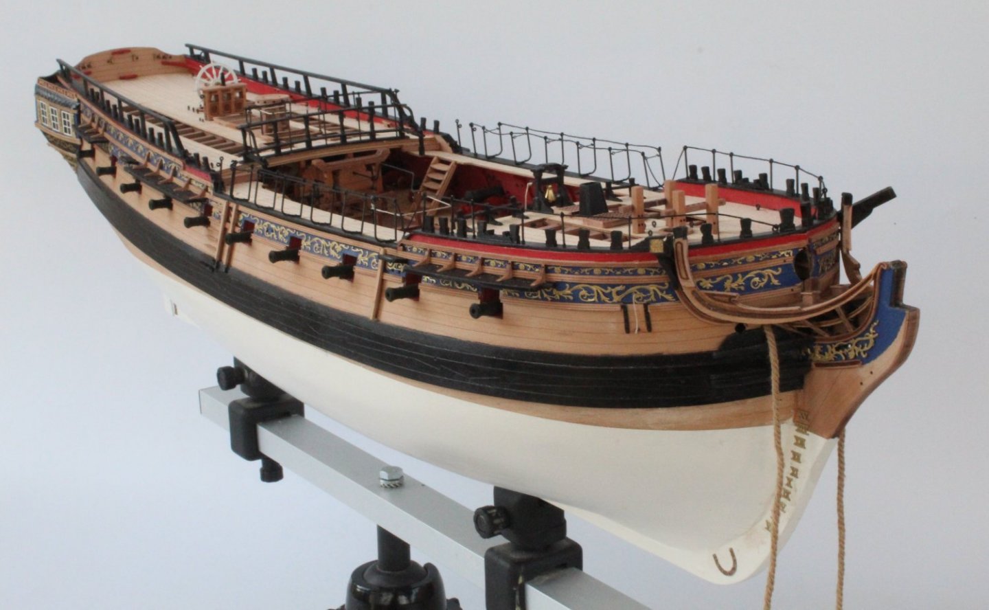
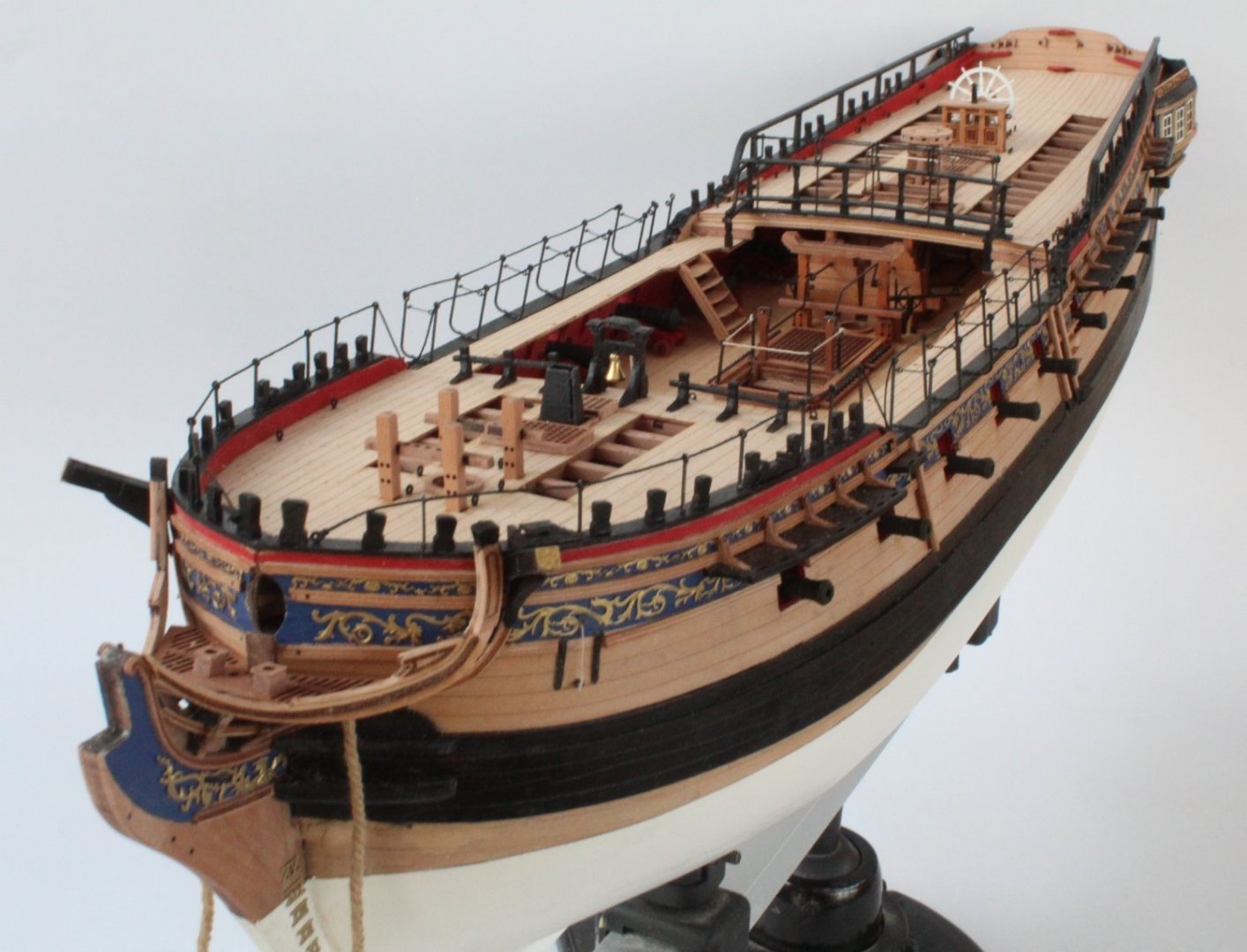
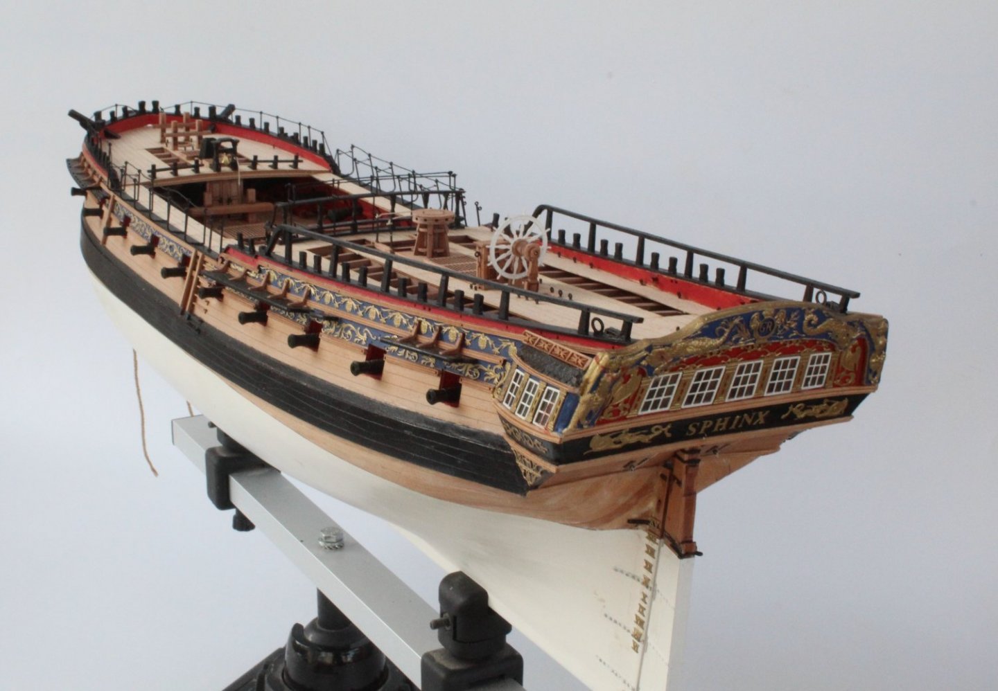
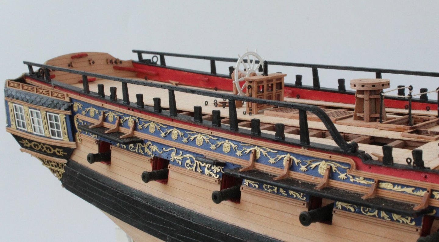
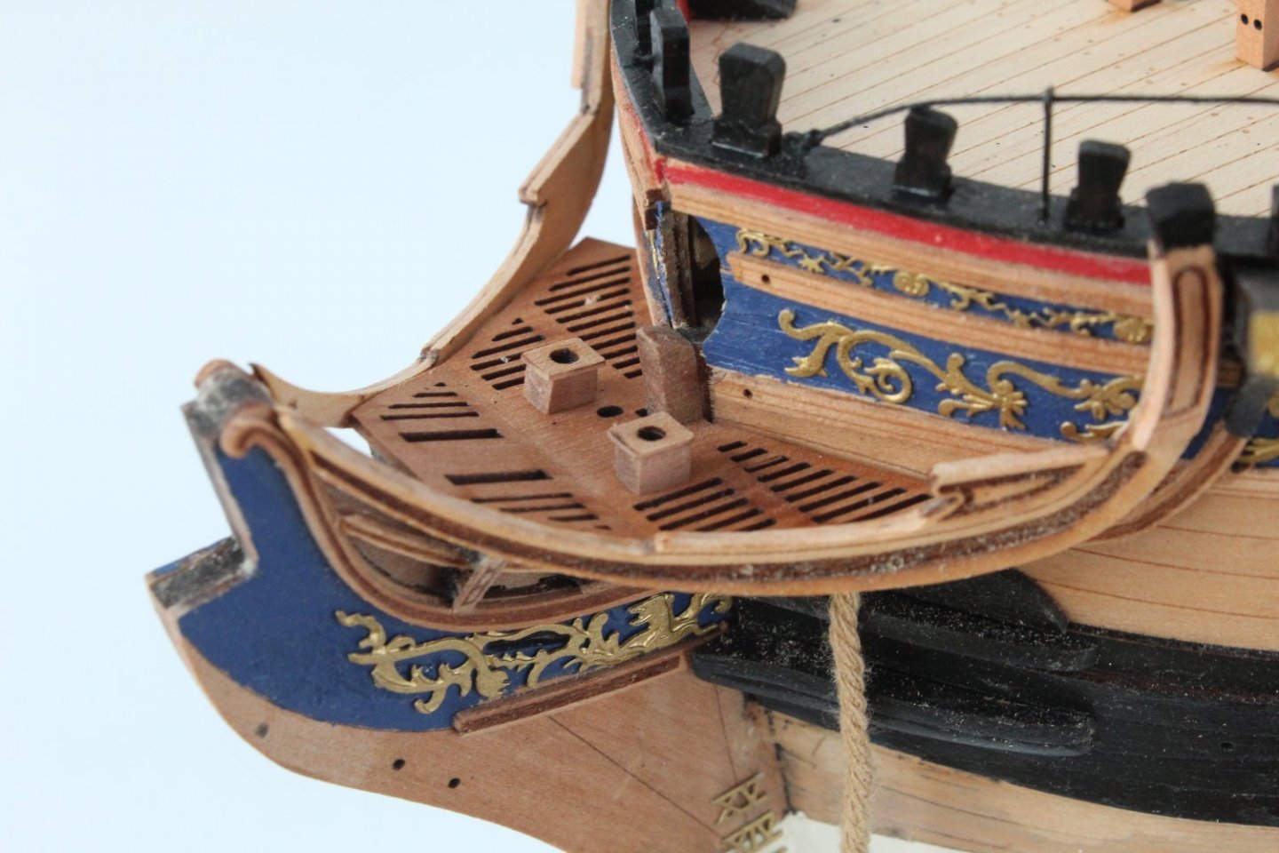
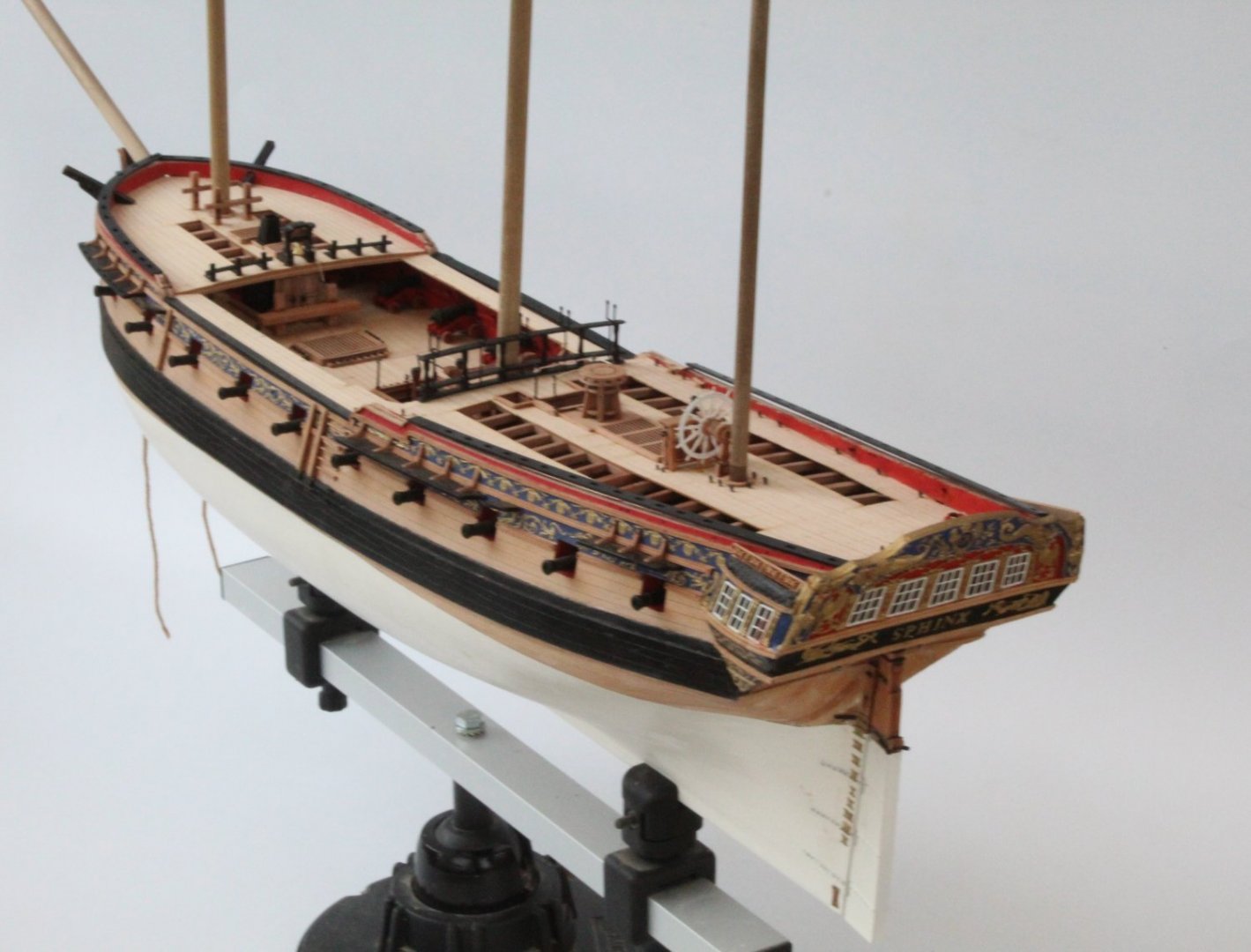
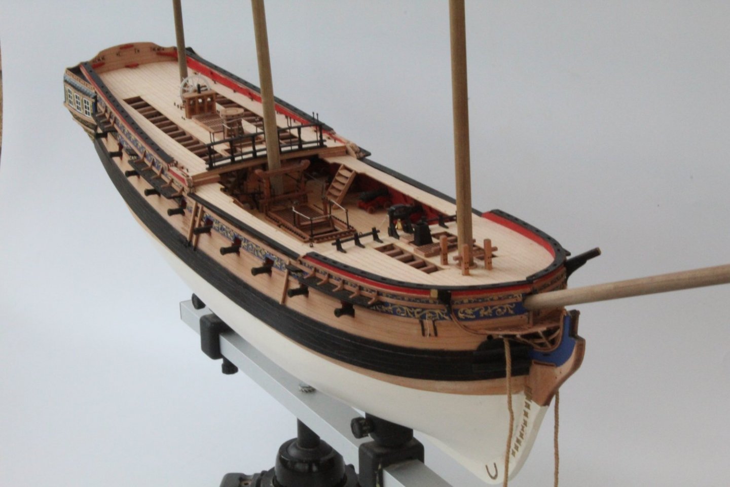
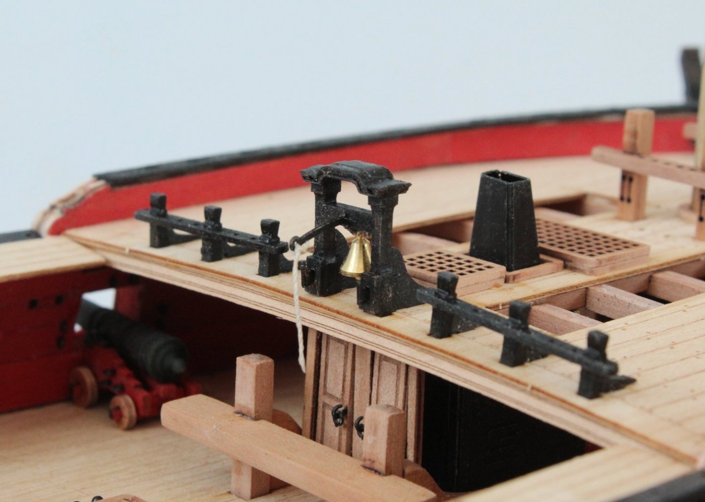
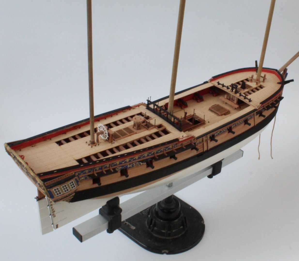
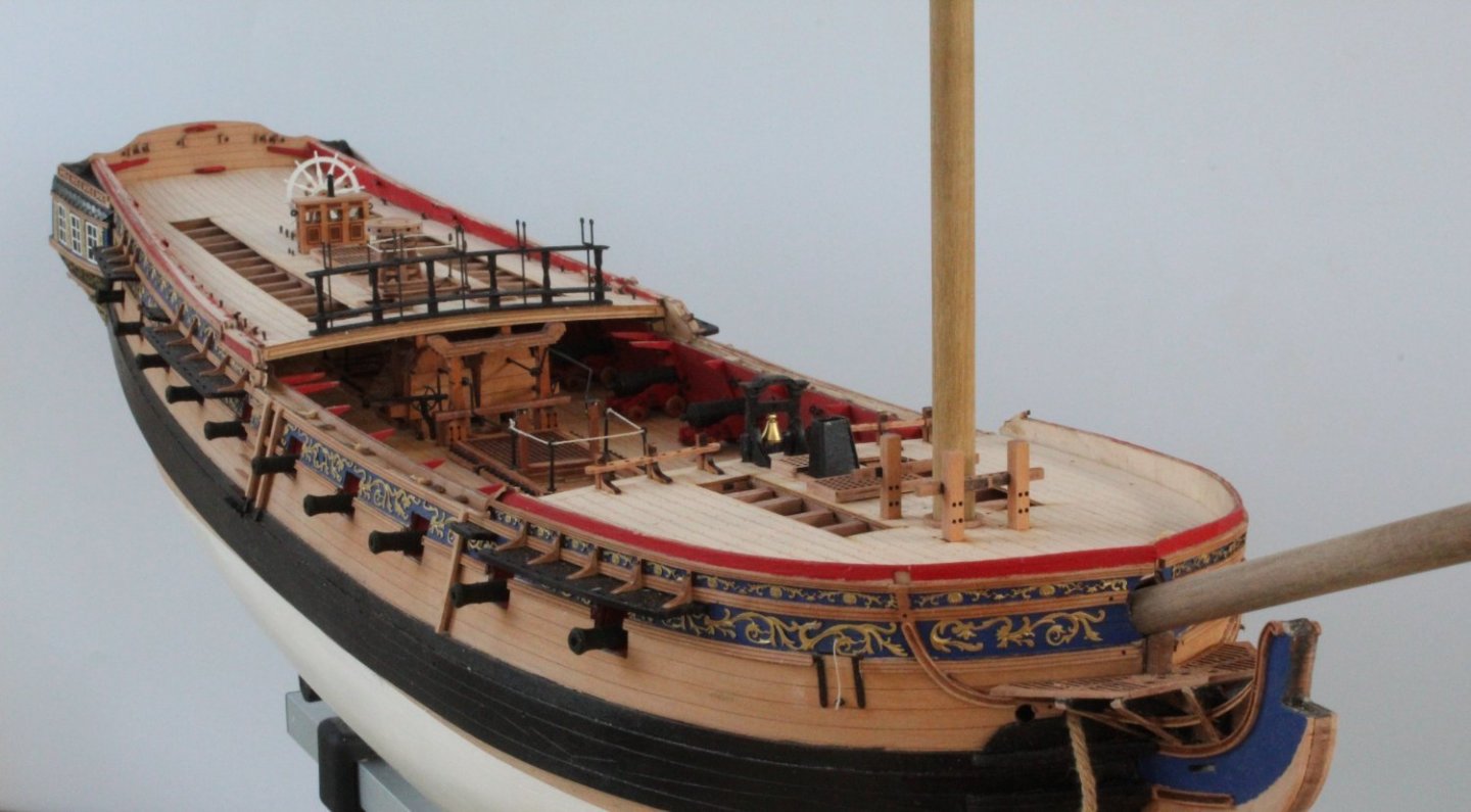
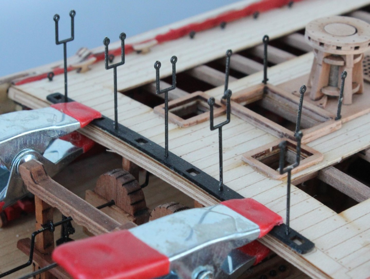
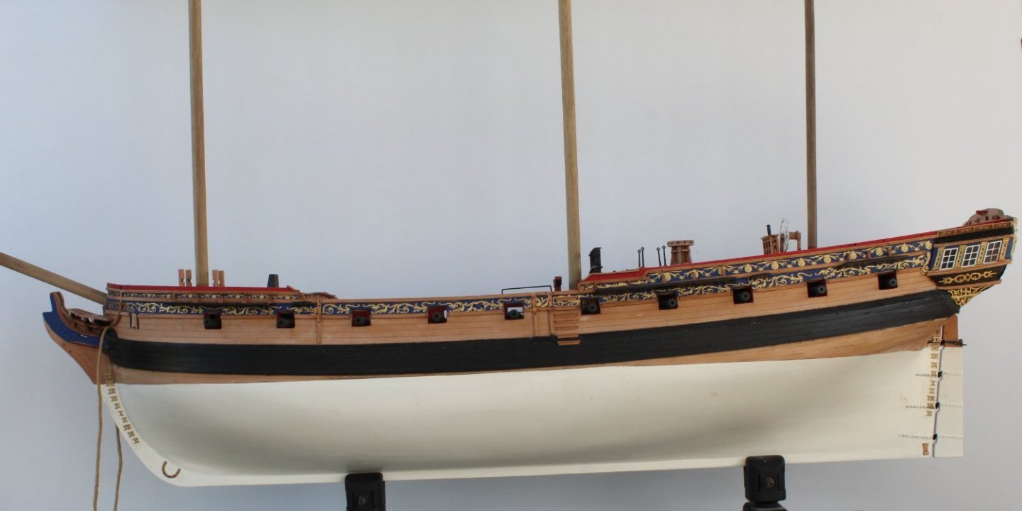
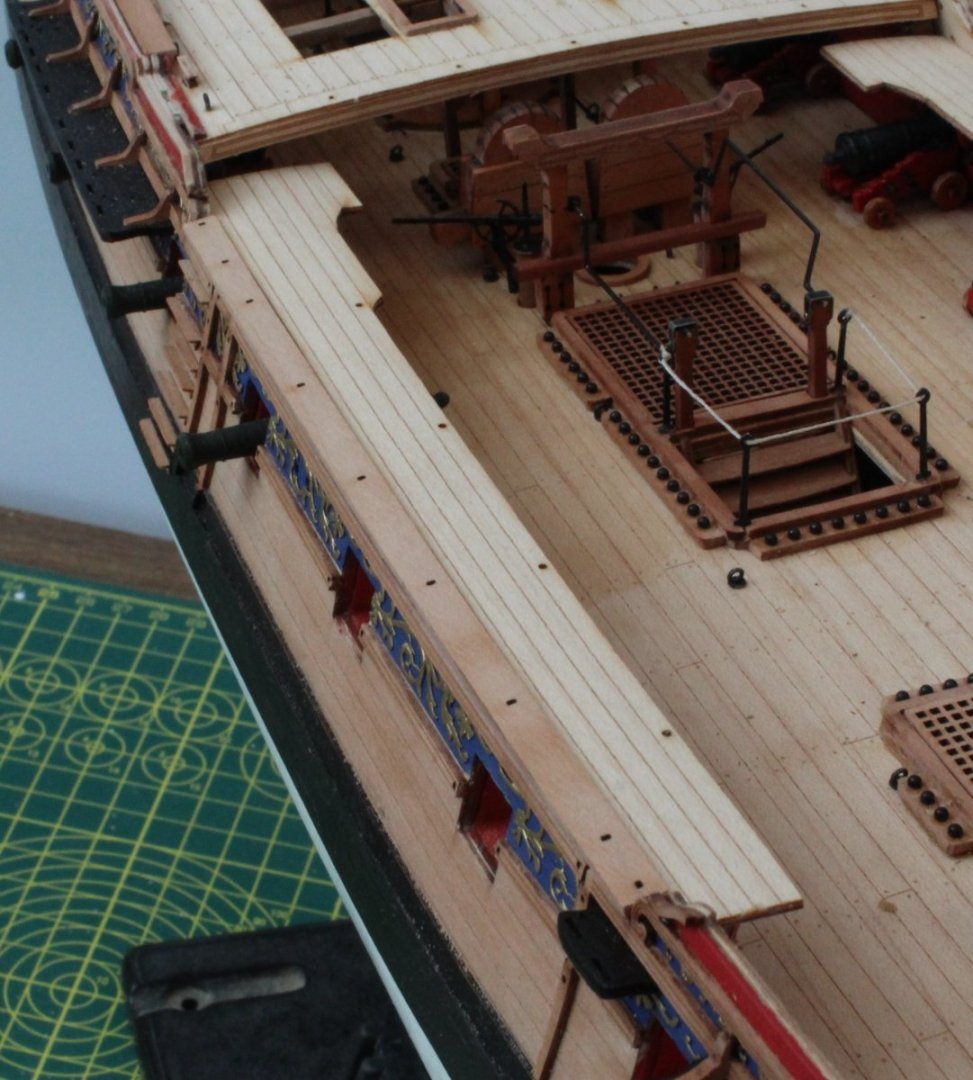
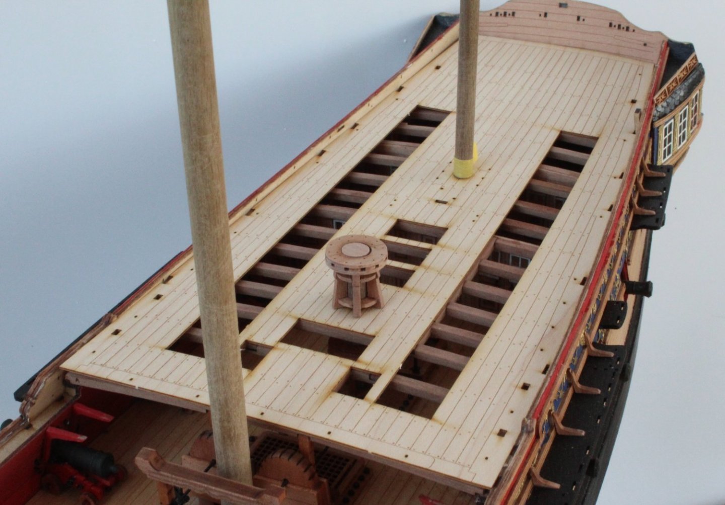
Deck Work - Nearing Completion I have made good progress over the last couple days and the work on completing the decks and hull is almost complete. I have attached three photo's of the current state of my Sphinx V2 build. I will then provide a bit more detail of the various bits added later on in this post. The gunwales were glued in place followed by adding the timberheads and fife rail supports for the quarterdeck. I lined the various timberheads and fife rail supports in the correct order on my workbench and then dry fitted them to the gunwales. With everything in place the slots of the underside of the fife rail slots were then checked with the position of the supports on the gunwale. With everything looking good I proceeded to glued the parts in place. I noticed the kit does have a set of hammock cranes for the quarterdeck section, which are shown on the plan sheets. It does not appear these were fitted on the prototype. I opted to follow suit. Picture of the fife rail and timberheads. I did not fill the pin locating holes after assembling the fife rail The quarterdeck breast rail assembly was then completed with adding the two stanchions to the walkway deck, the support bracket to link the stanchions with the breast rail assembly and the two hand rails down to the walkway deck. I used 0.5mm black thread to rig the hammock cranes. I then built the two bow main rails and rounded the top section as detailed in the build manual. I did manage to break the top parts of both main bow rail assemblies but thankfully I was able to repair them both before they were glued in place. I am not totally happy with how they sit against the side of the hull but they do sit flush with the sides of the bow grating deck which was my main aim when fitting them in place. The timberheads, hammock cranes and eyebolts were added to the forecastle and walkway gunwales and then they were rigged using 0.5mm black thread. The final items added to the Sphinx were the two seats of comfort to the bow grating deck and the two PE hull decorations which sit either side of the stem post beneath the bow grating deck. I have started work on the two lanterns, I am currently painting the resin parts. I also have the 6 off gun port lids to build which will be my next task. I also need to add rudder chain. Once all that is done I can either start work on making all the yards and masts or I can try building the small boats. I suspect I will split my time between mask/ yard fabrication and small boat building. I think the small boat build will be quite a challenge for me.


- 476 replies
-
- 17
-
-

-
- sphinx
- vanguard models
- (and 1 more)
-
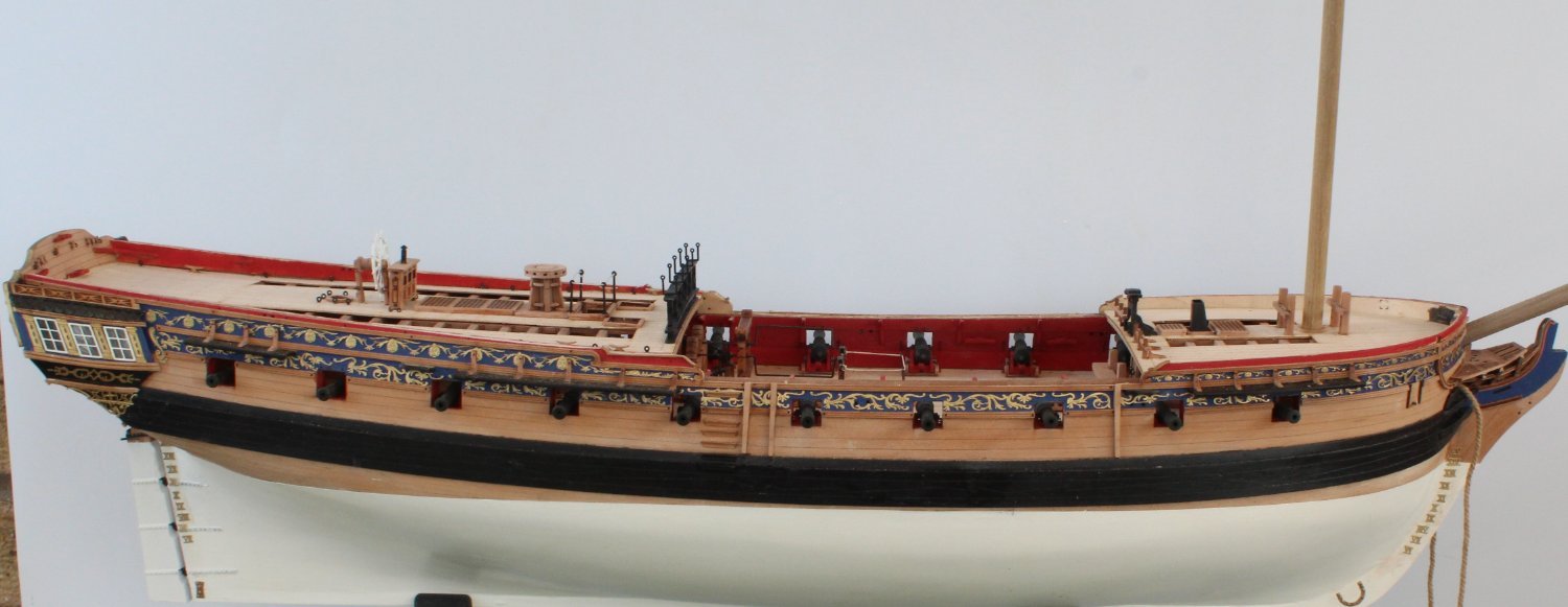
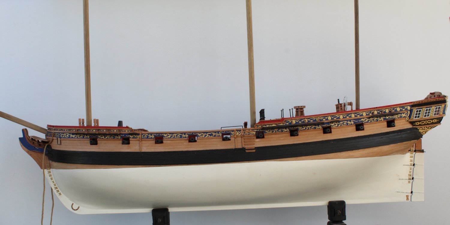
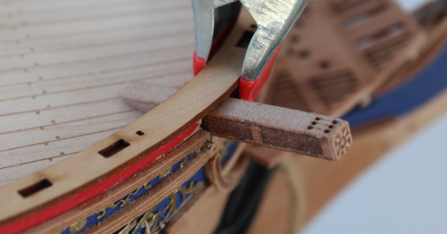
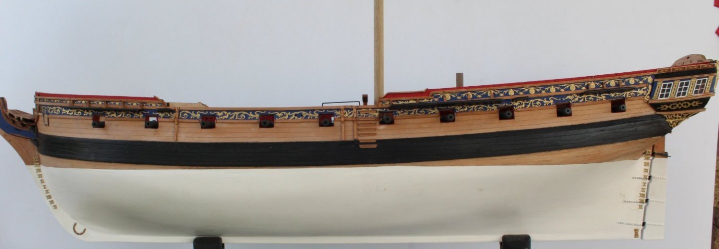
Decks The forecastle deck work is now completed, with the exception of adding the eyebolts, belaying pins and gunwales complete with timberheads and hammock cranes. The gunwales have been painted black and are ready to be secured in place. I plan to dry fit the timber heads prior to securing the gunwales in place just to make sure there are no unforeseen installation problems. As can be seen in the photo below I painted the catheads and cathead knees black but opted to paint the front pattern gold. The forecastle breast rail assembly was a great fit, as was the belfry. When fitting the breast rail one of the knees, when coated with glue sprung away from my pliers. I spend a fun 20 minutes searching everywhere for the missing knee which I eventually found it in a dish where I keep the all the unused cut-outs from the various decks. The dish is kept on the window ledge next to my workbench so it was an amazing leap for the knee to end up there! The more eagled eyed will also spot the walkway does dip down a little in this photo. There is not a lot I can do about that now but once the Sphinx is fully rigged I am sure will not be noticed. The two walkways have been added as have the two steps to the quarterdeck and ladders from gundeck up to the walkways. I should have trimmed the width of the two steps so they were the same width as the walkway - oops! All the gunwales have been painted black and test fitted. They are shown in the following three photo's but they are only placed in position and are waiting to be glued in place which will explain the gapping that can be seen. A slightly out of focus full length shot of the current build status

- 476 replies
-
- 13
-
-
- sphinx
- vanguard models
- (and 1 more)
-
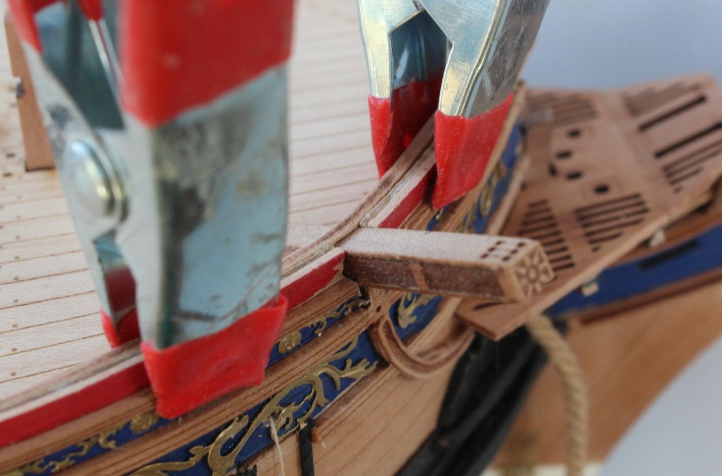
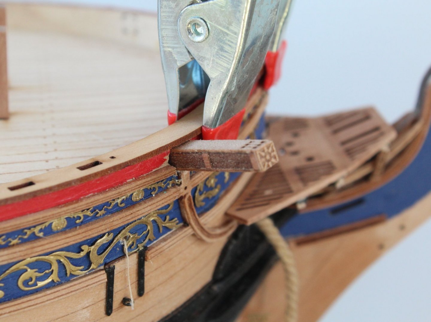
Catheads I did not have too much time to spend in the shipyard today. The forecastle inner bulwarks had been soaked and clamped to the hull last night prior to fitting. Before fitting them I decide it would be a good idea to assemble and test fit the catheads. The assembly of the catheads was a simple task. The access slot for the catheads through the hull does require opening up however. In the build manual this was done after the inner bulwarks and gunwales had been fitted. I thought it might be a bit easier to open up the hull for the catheads before the inner bulwarks and gunwales were fitted. The bulwarks could then be worked on before fitting. I started by placing the cathead on top of the hull, centrally to the pre-marked cutout for the catheads, and made two pencil marks. I carefully removed the excess wood, using some tape to protect the forecastle deck. I took my time with this task, checking the fit of the cathead several times. Once I was happy with the cutout I clamped the inner bulwark to the hull and marked where the excess material needed to be removed. Once again I took my time with repeated checks. It might not be the best method but it certainly worked well for me. The following photo was after I had started work on opening up the inner bulwark which had then been clamped in place for a fit check. The outer hull will require a little bit of paint touch up. A little bit more work is required on the inner bulwark as the cathead is not quite sitting flush on the deck IN the next picture I am checking the fit with the gunwale clamped in place, all looks good. The cathead is now sitting flush on the deck. I will need to open up the cathead holes on the finishing inner bulwark patterns also. My best guess estimate is that I will complete all the hull work in the next 2 to 4 weeks. I will then move to manufacturing the bowsprit, masts and yards. I also have the three small boats to build. Exciting times ahead.

- 476 replies
-
- 10
-
-
- sphinx
- vanguard models
- (and 1 more)
-
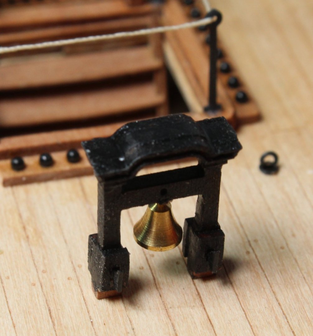
Forecastle Deck The forecastle deck has now been glued to the support beams. I was really happy with the end result. I have also dry fitted all the deck items and everything seems to be a good fit. The belfry assembly has been painted black. The forecastle breast rails / knees have been assembled but they have to be painted black before they can be glued in place. The coaming / grating assembly has had the laser char removed and is now ready to be glued in place. The two foremast bitts have been glued in place but the two crossbeams are only dry fitted as I will need to check the belaying pin fit before they can glued in place. My next task will be to add the inner bulwarks and deck iron work before moving on to adding the two walkway decks. I also completed the work on the quarterdeck breast rail assembly. The hammock cranes rigging will be done once all the deck work has been completed. This is a nice view of the three decks.


- 476 replies
-
- 12
-
-
- sphinx
- vanguard models
- (and 1 more)
-
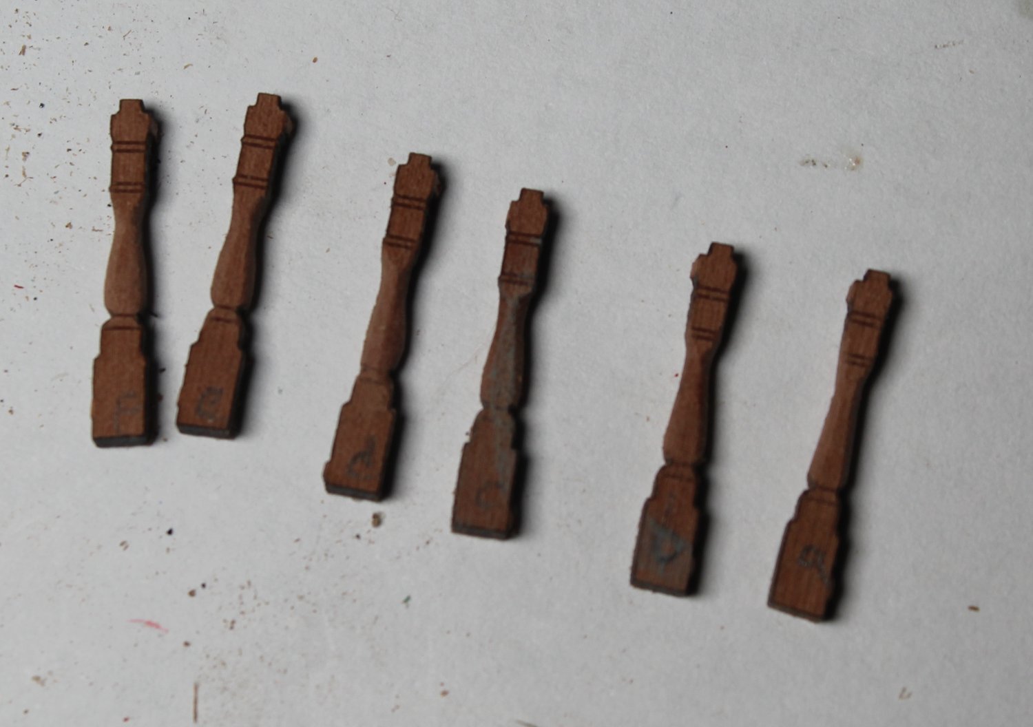
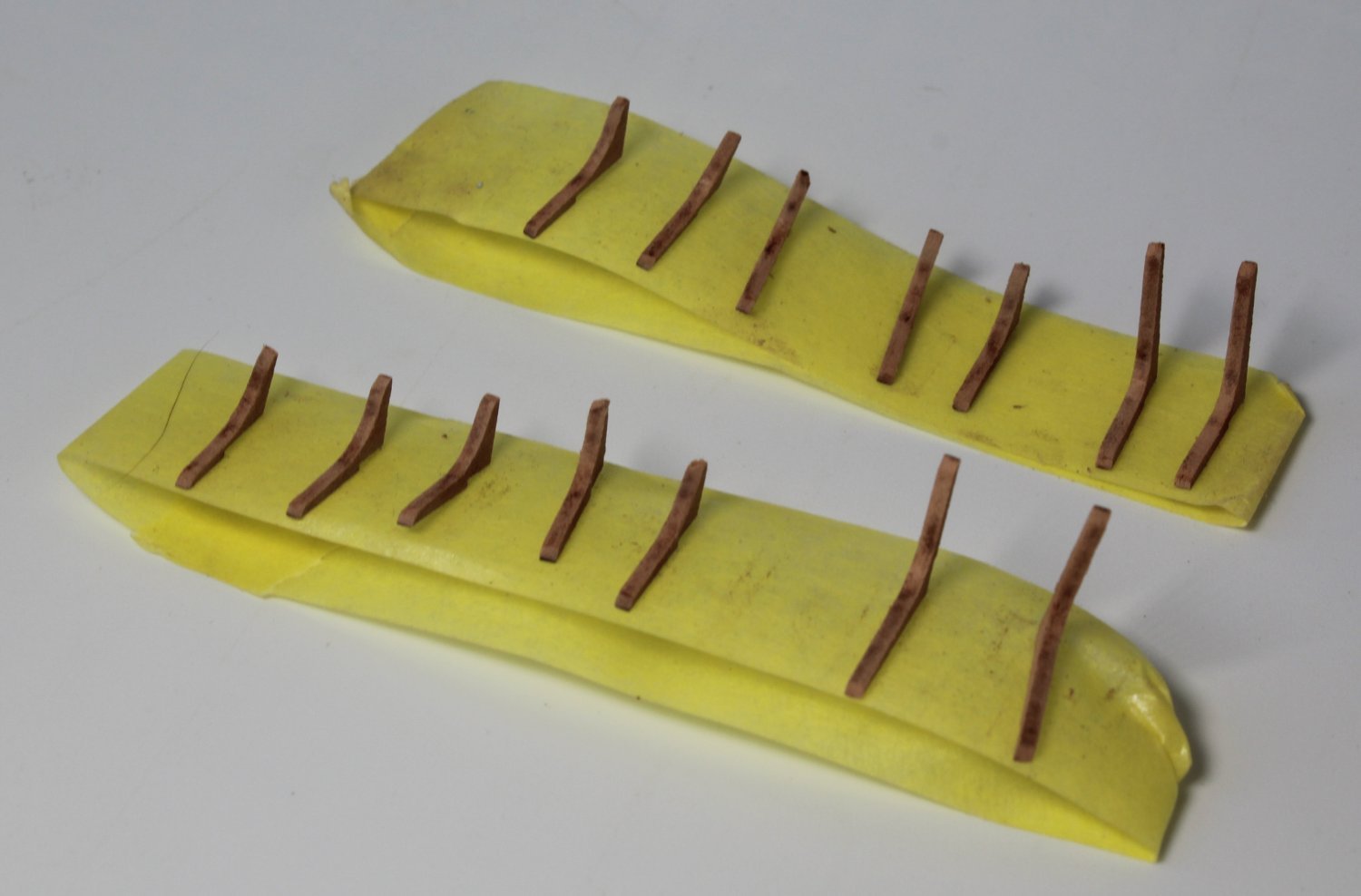
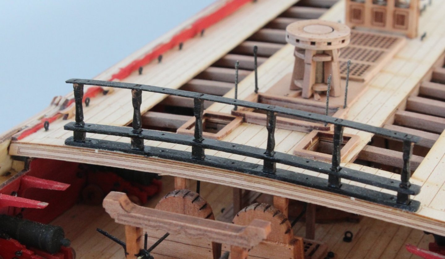
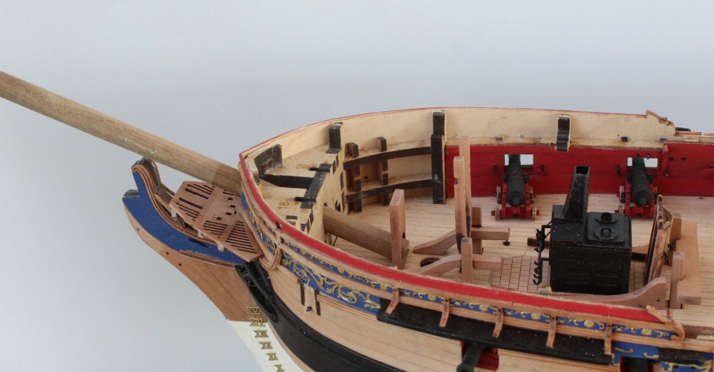
This post is going to cover two different areas of the build, the quarterdeck breast rail assembly and the work on the bow area of the gundeck under in preparation for adding the forecastle deck. Quarterdeck Breast Rail Assembly The quarterdeck rail assembly comprises 4 rails (bottom, middle and 2 top rails), 6 breast rail stanchions and 5 hammock crane supports. The four rails were painted black before the installation phase. The centre section of each breast rail stanchion requires rounding. I used a thin Florey sanding stick and some sandpaper to complete this task. I did add a letter identifier to each stanchion so they could be installed in the correct place. When the bottom rail was added to the quarterdeck I used the hammock cranes to ensure the rail was correctly positioned. A couple of clamps were also used to bend and hold the rail in place as the glue cured. Once the bottom rail was secure the stanchions and middle rail were glued in place. The top rail was dry fitted to ensure the stanchion were correctly aligned. The tops of the stanchion require a bit more black paint before the top two rails can be glued in place. Bow Area Gundeck Work The various deck items that reside under the forecastle deck were glued in place. The bowsprit and foremast were also test fitted to double check they would fully locate in the slots provided. The remaining 8 cannons, 4 per side were glued in place. The two ropes for the anchors were fed through the hawse holes and forward bulkhead. The rope ends were tied off to prevent them being pulled back out. The forecastle deck support beams were glued in place. I did have one or two issues, mainly with the z beam joint with the longitudinal deck beam and gallery door frame. However what happens under the forecastle deck remains unseen under the forecastle deck but I was able to resolve the issues and the forecastle deck was dry fitted without any issues. The foremast, bitts and stove chimney were also dry fitted to ensure there were no alignment problems. The ships belfry was dry fitted for a photo opportunity, noting it is not sitting fully in the slots in the photo below Finally a nice shot of the hull with masts and bowsprit in place and anchor ropes in place. The items on the quarterdeck and forecastle deck can be seen


- 476 replies
-
- 14
-
-
- sphinx
- vanguard models
- (and 1 more)
-
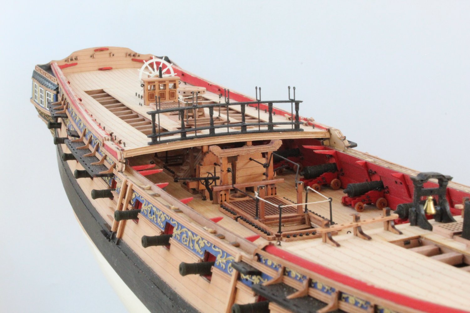
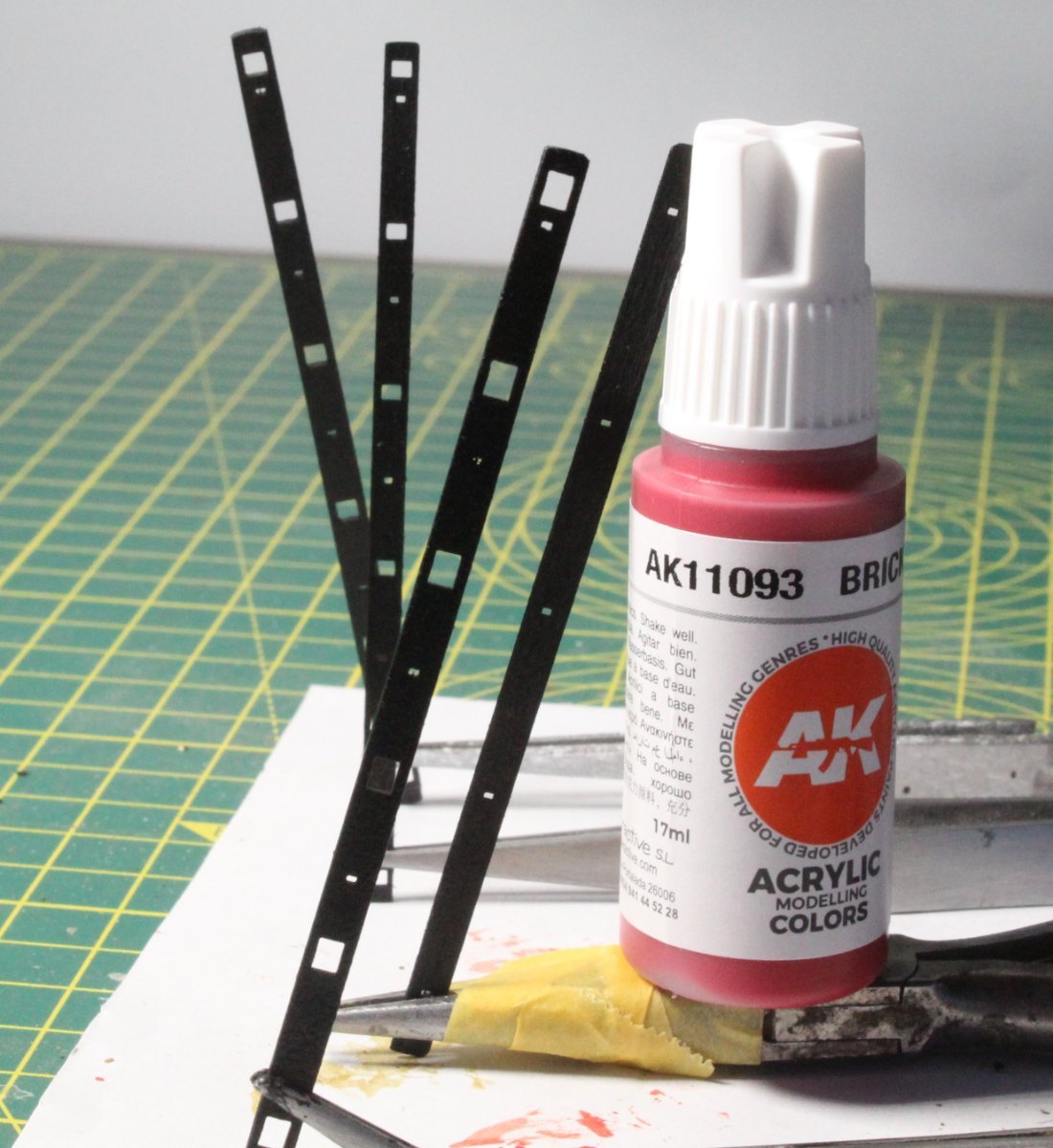
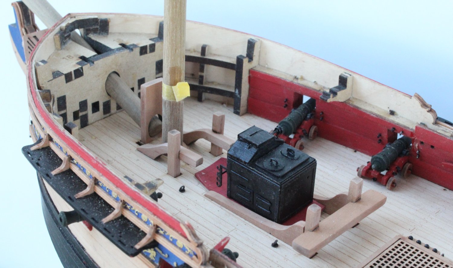
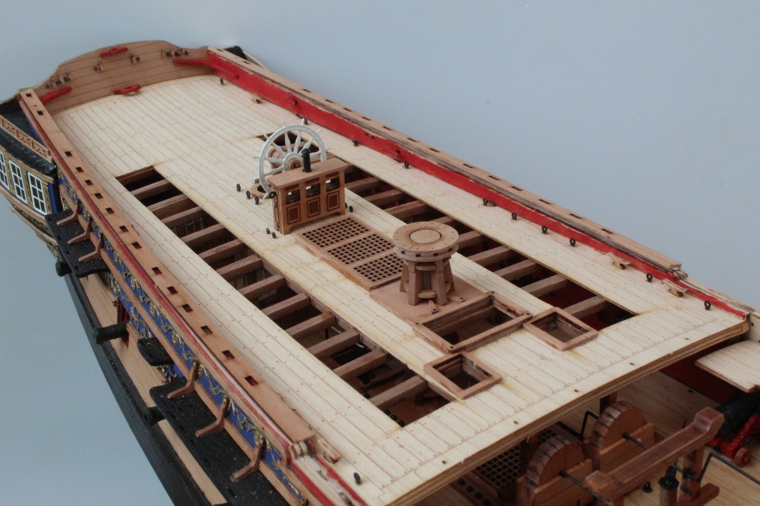
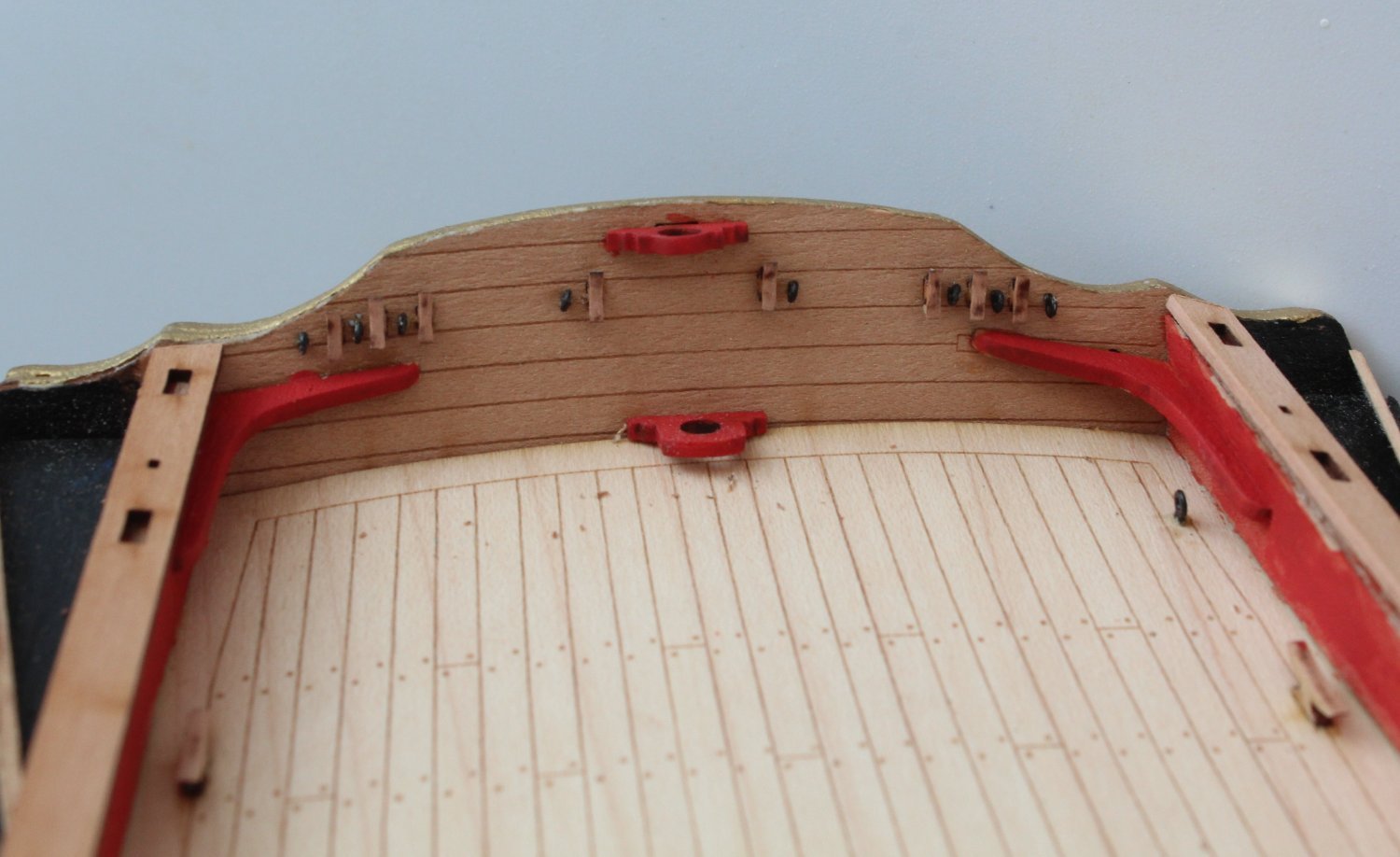
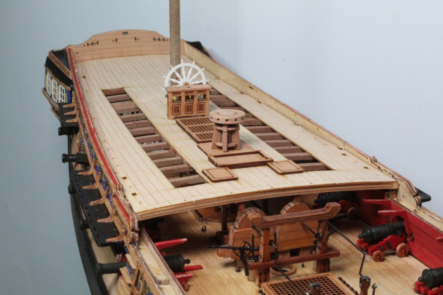
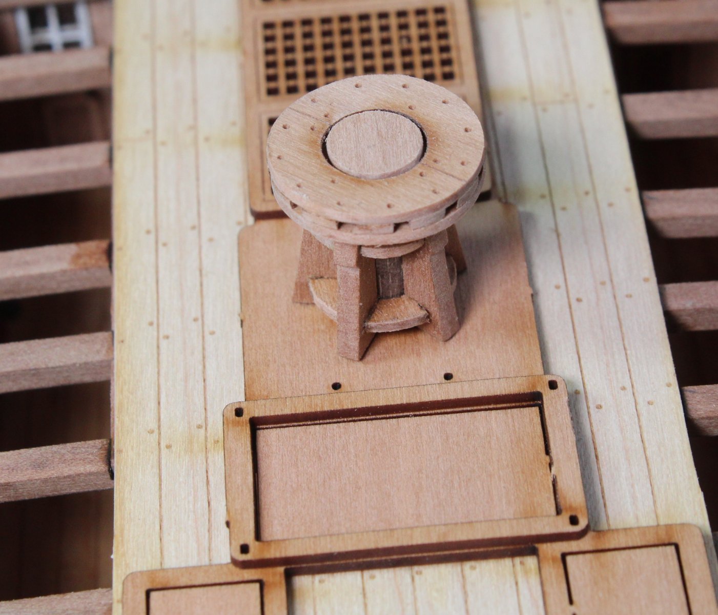
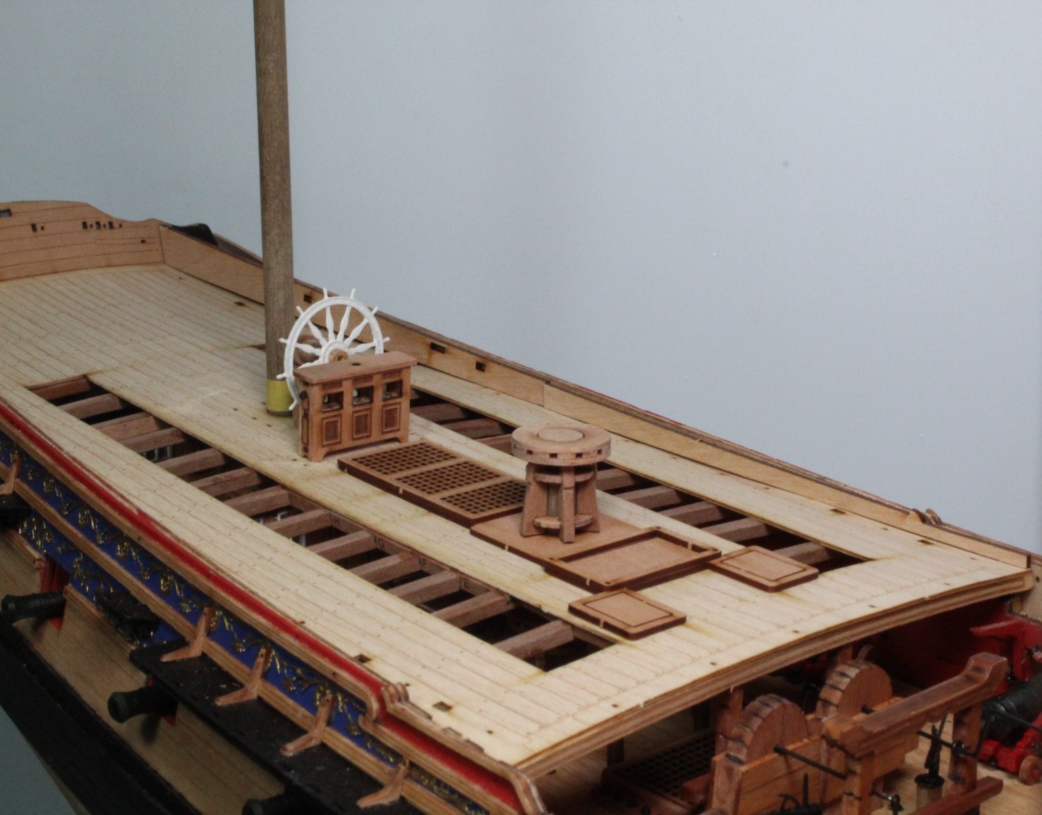
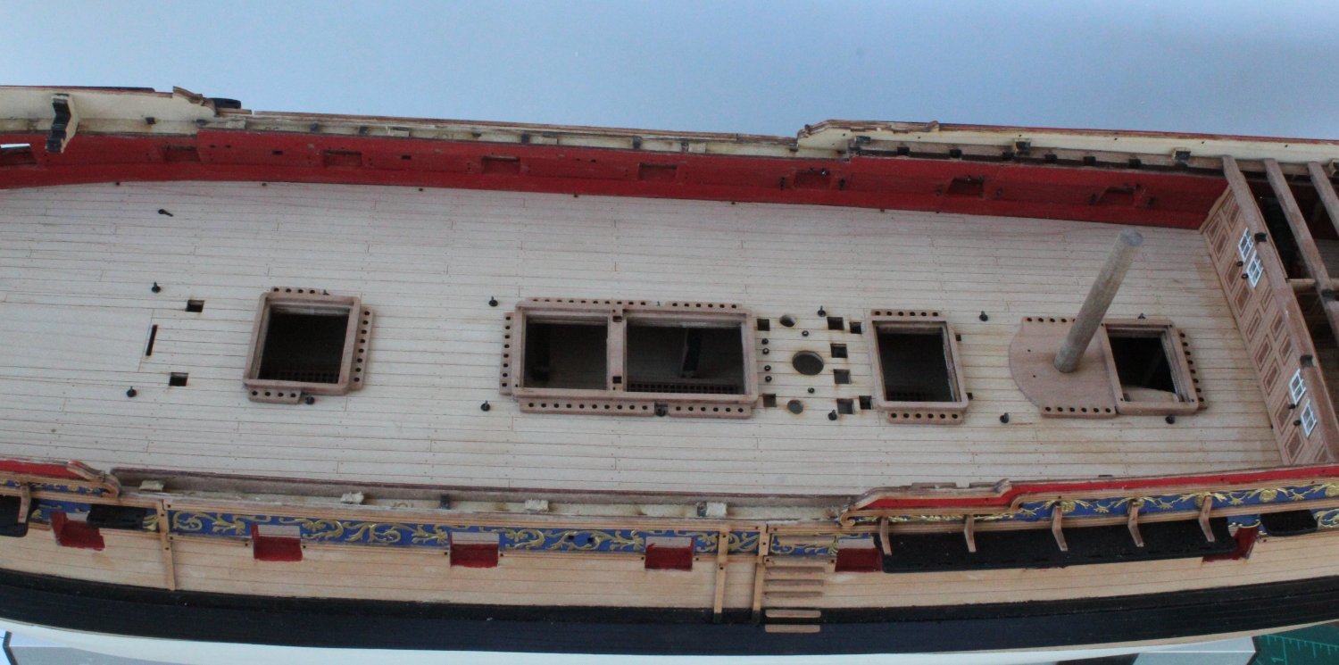
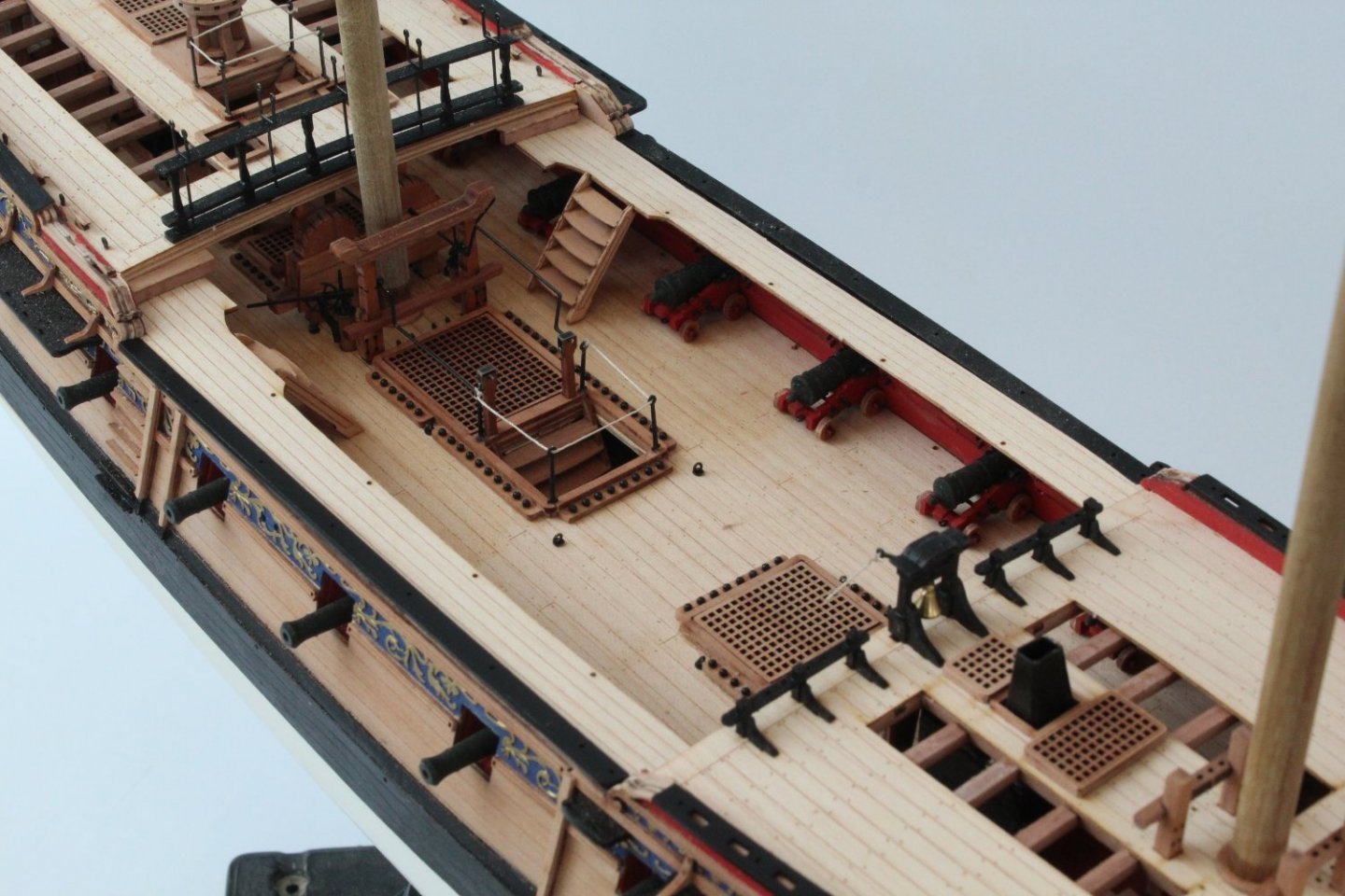
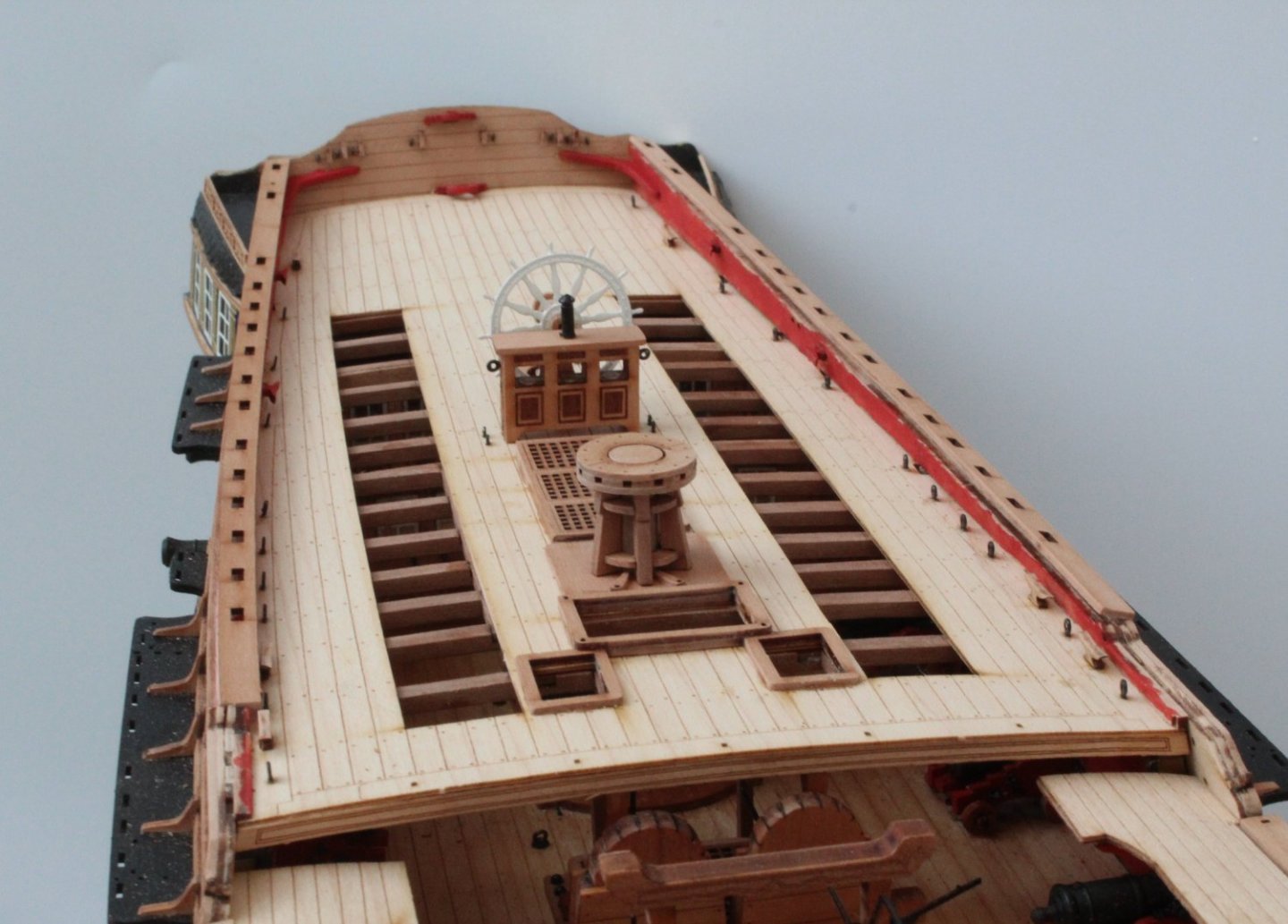
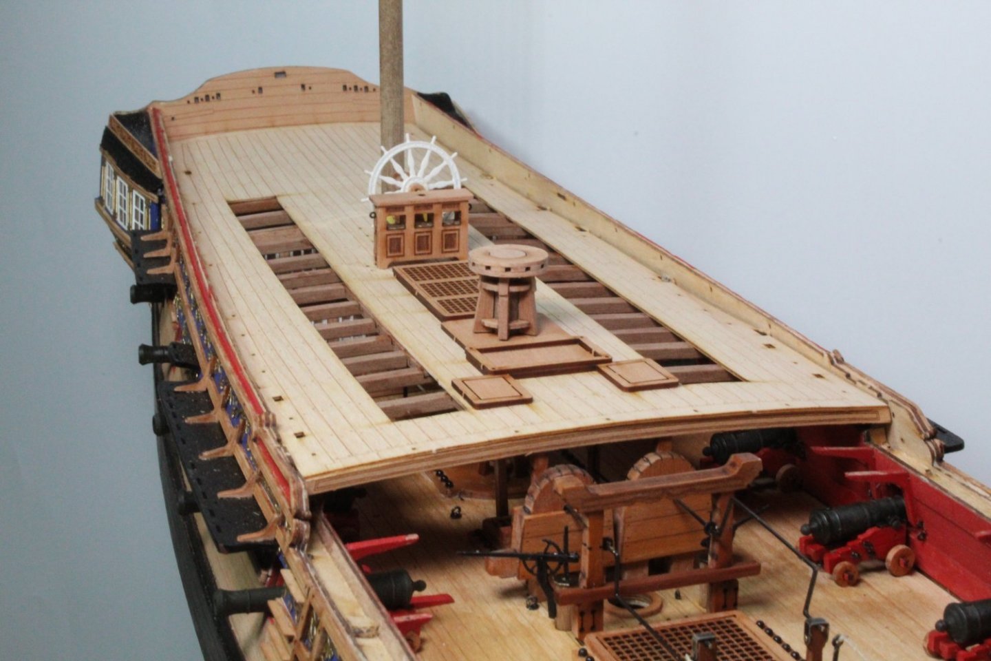
Quarterdeck Work I have made quite a bit of progress with the quarterdeck. The inner bulwarks have been fitted and painted. The various cleats, eyebolts, flag holder, etc. have been fitted. I have also added the grating assembly (ladders still to be added), ship's wheel, binnacle and capstan. I decided to leave the capstan in it's natural state. The top of the bulwarks have been filed and sanded in readiness for the gunwales. There is a few more tasks to complete, such as adding the quarterdeck rail assembly to the front edge of the quarterdeck. With regards to the stern fascia I opted to leave it with the natural pear wood finish but painted the transom knees and both stern ensign staff brackets red. I have also built and test fitted the two walkway decks. I did cut a section out of each walkway, as detailed in the build manual, for the gunwales. In the photo below the walkway and associated gunwale have been dry fitted. These will be added once the forecastle deck has been fitted. The brick red paint I ordered for the stove base is out for delivery and will arrive later today, so I hope to be in a position to start work on fitting the forecastle deck later this week.


- 476 replies
-
- 17
-
-
-
- sphinx
- vanguard models
- (and 1 more)
-
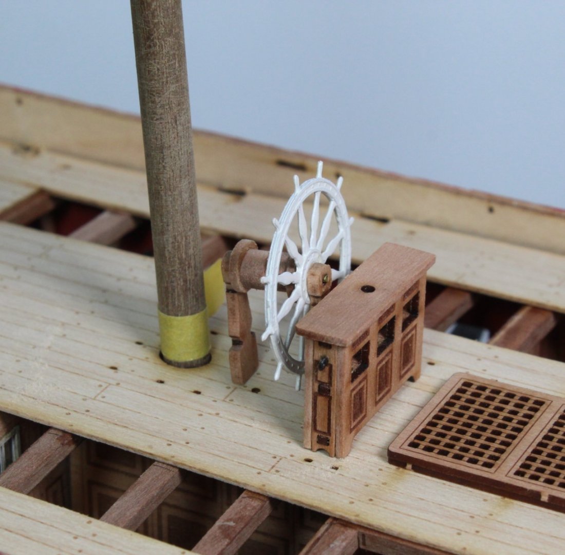
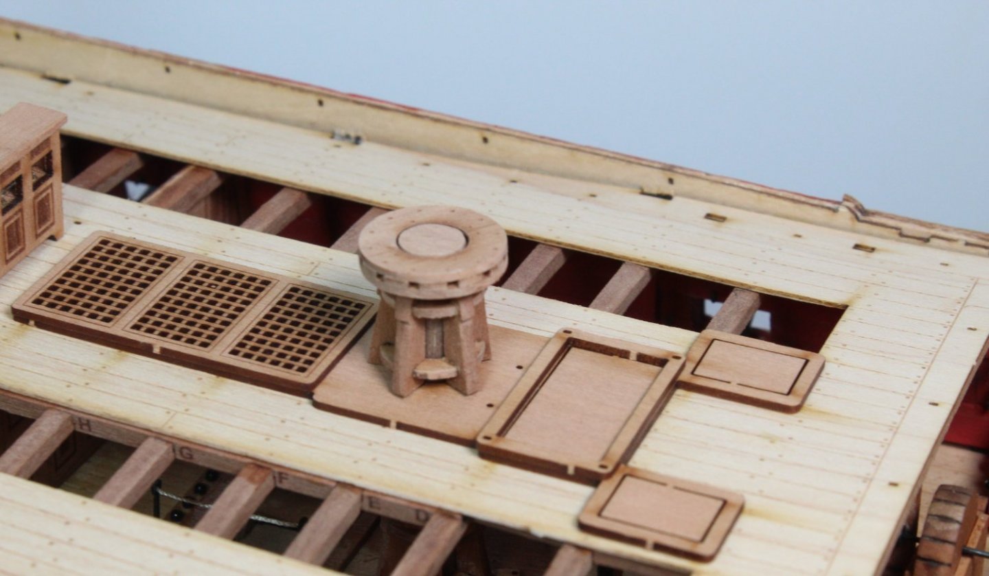
Quarterdeck work I started today with a few simple assembly tasks starting with the belfry required for the forecastle deck. The belfry knees and handle have not been added as yet. I then moved on and built the binnacle and ships wheel. The brass binnacle chimney part has not been fitted as it currently in the paint shop where it has had coat of primer and a coat of black paint. After a trial fit I went ahead and glued the quarterdeck in place. Once the glue had cured I placed the various deck items in place, dry fitting only at this stage. I have also test fitted the various cleats in the stern fascia panel and inner bulwarks. The two holes required for the two lanterns have also been drilled through and then checked that the brass rod will pass through. Close up of mizzen mast, ships wheel and binnacle Close up of capstan Capstan and coamings. In the final picture of this post I have added the inner bulwarks, noting they are not glued as I need to sand flat the removed bulkhead tabs


- 476 replies
-
- 10
-
-
- sphinx
- vanguard models
- (and 1 more)
-
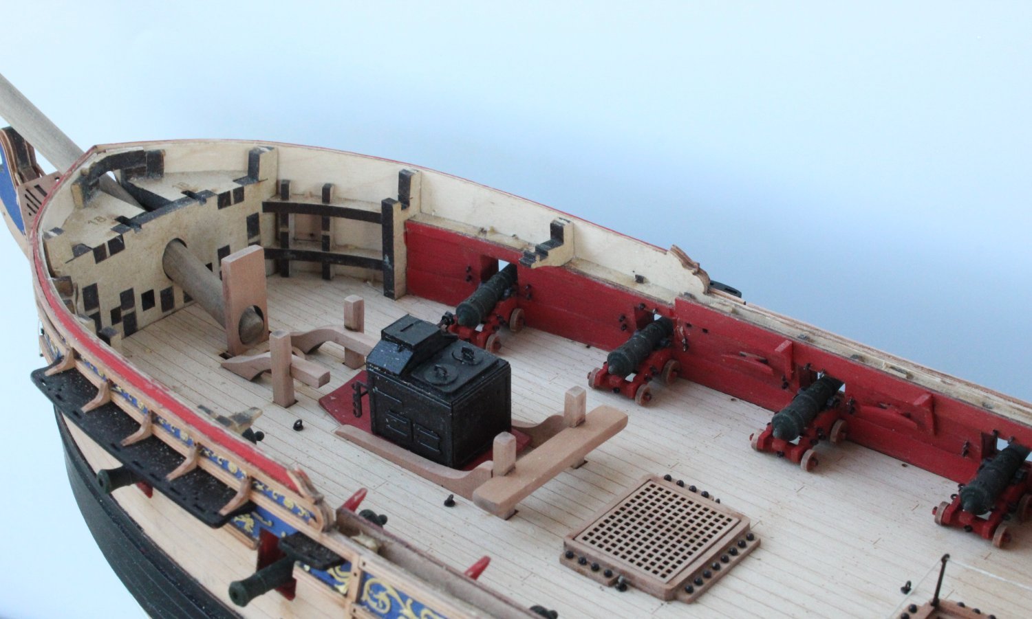
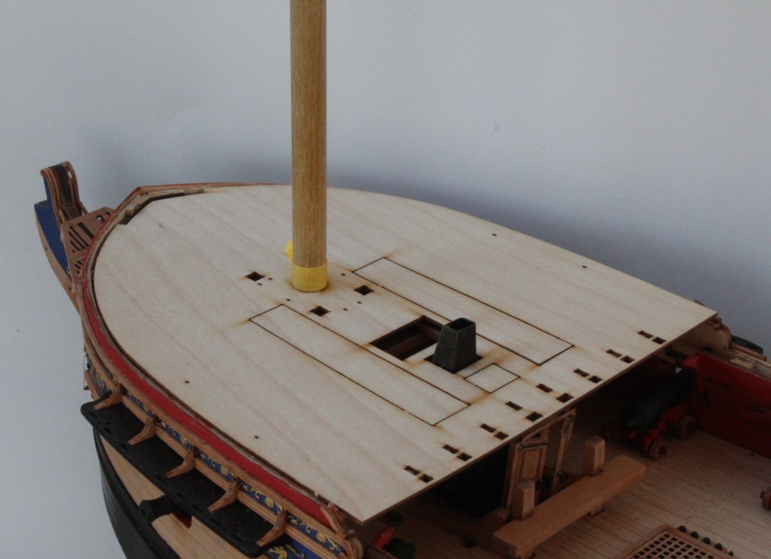
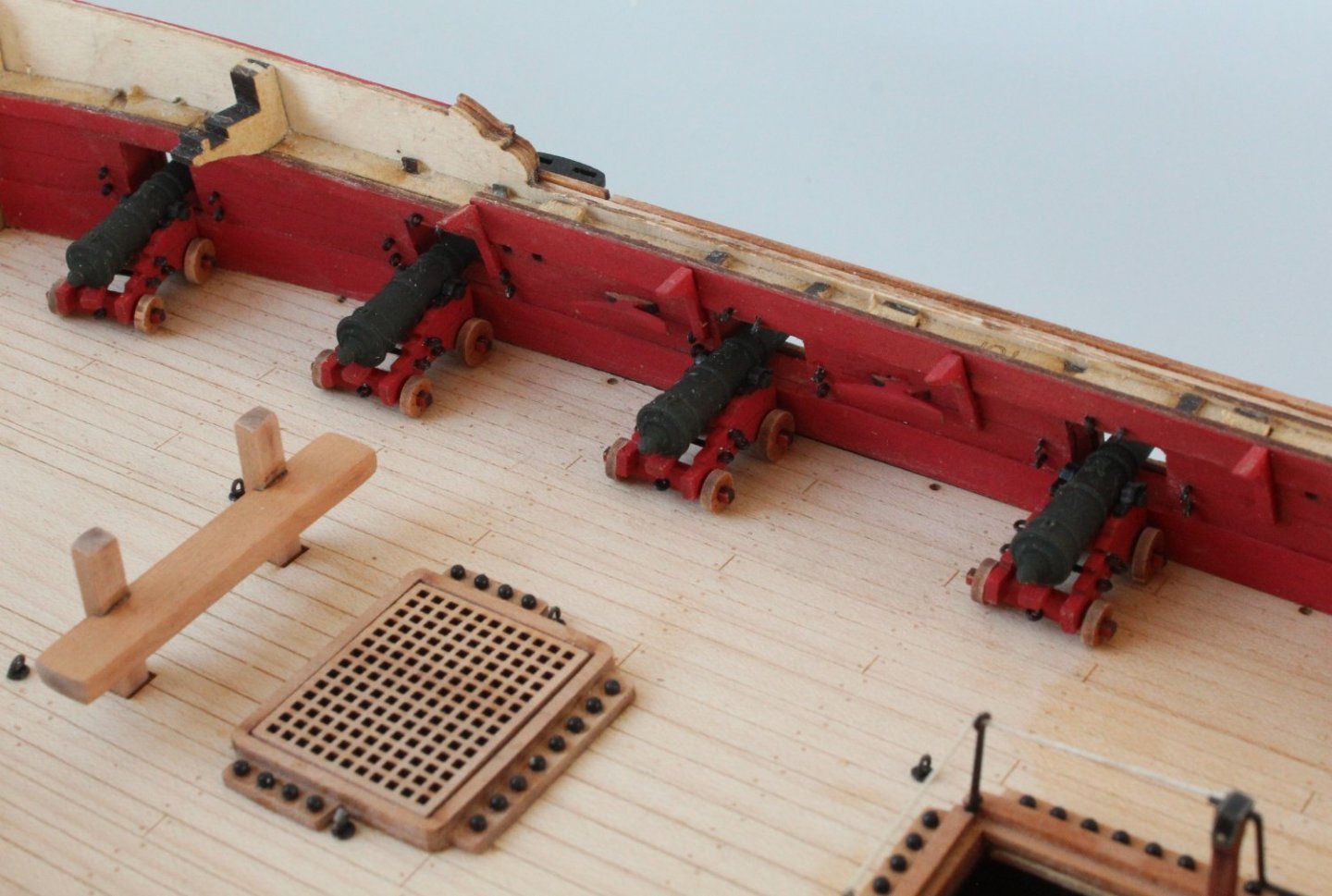
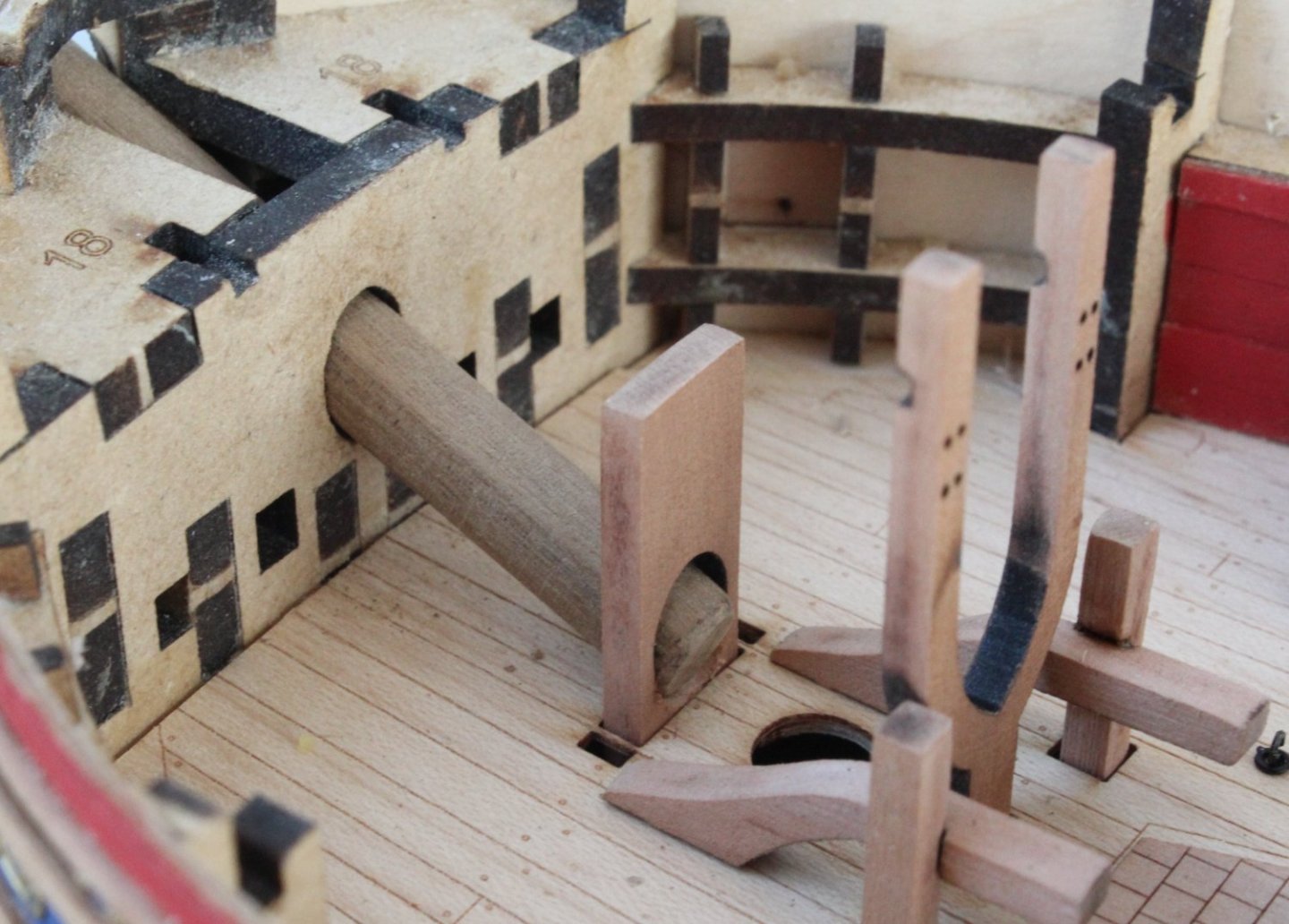
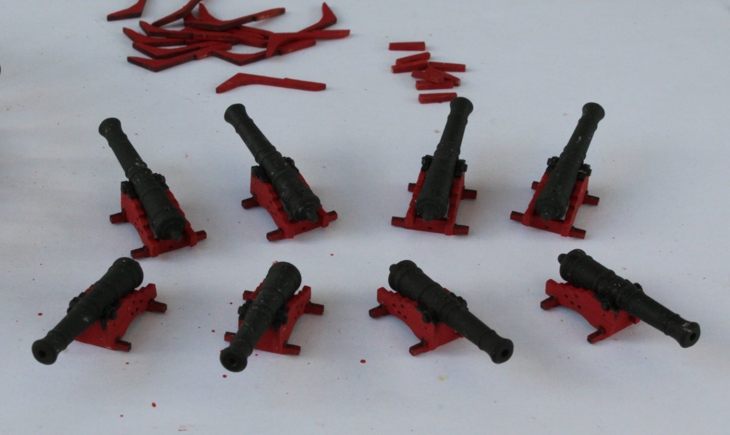
More Deck Work - Cannon, Bowsprit, Quarterdeck and Forecastle Deck The remaining 8 cannons have now been assembled. I have added them to the deck in the following two pictures, but they have not glued in place for the time being. Closeup of one side, the two wooden cleats can also be seen as can the walkway deck hanging knees The Sphinx guns are ready and waiting to fire a broadside to any enemy ship I then decided to check the fitting of the bowsprit dowel. Initially the dowel would not fit through the access hole at the front of the bow. This was to be expected as the build manual did show the hole being enlarged. I used a large round file to gradually open up the hole. After a few minutes work the dowel passed smoothly through the hole and through the hole on the bulkhead. I did camphor the bottom edge of the bowsprit support to complete the process. A close up of the bowsprit dowel located through the hull, bulkhead and support A photo showing the bow area, noting all the deck items are still dry fitted at this stage. I have ordered some brick red paint for the stove base which will probably arrive on Tuesday. I already have a grey wash for the tile edges. Therefore my next task will be to remove the laser char from the forecastle deck support beams and carlings. However before I start this task I decided to test fit the quarterdeck. I was very pleased that the deck was a perfect fit. The mizzen mast and capstan dowels were also test fitted without any problems. Using the "unplanked" forecastle deck I did a dry fit. Generally it would appear to be a good fit but it will require a little bit of sanding in a couple of places. The foremast and stove chimney could be positioned without any issues. Once the forecastle deck support framework has been installed I will use the "unplanked" forecastle deck as a template, and once I am happy with how it fits it will used with ensuring the "planked" forecastle deck is a good fit before it is installed.

- 476 replies
-
- 13
-
-
- sphinx
- vanguard models
- (and 1 more)
-
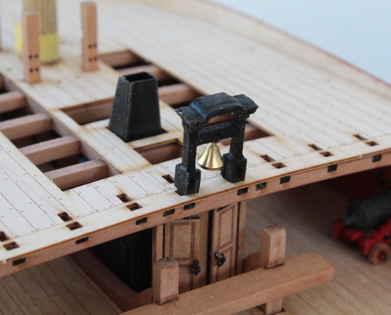
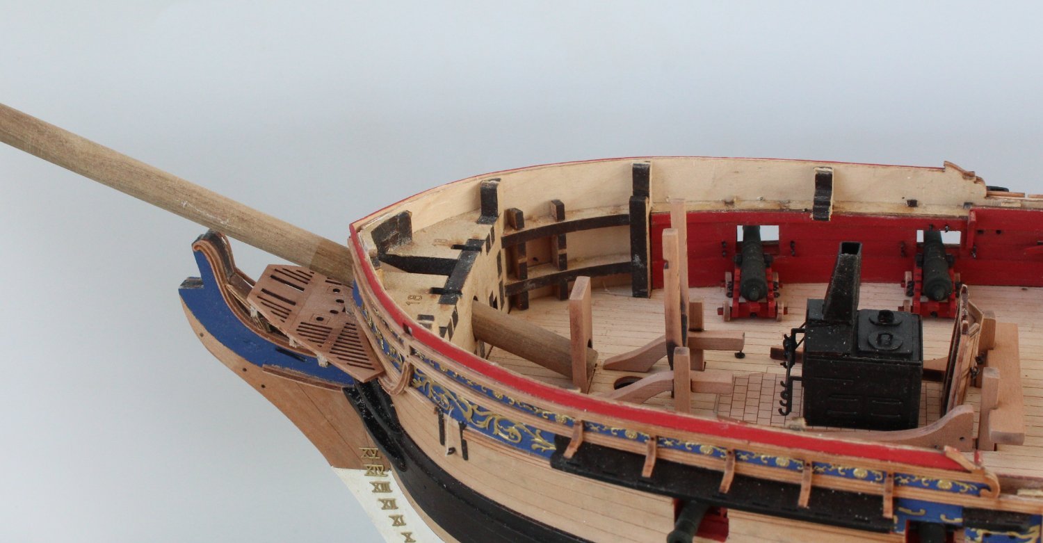
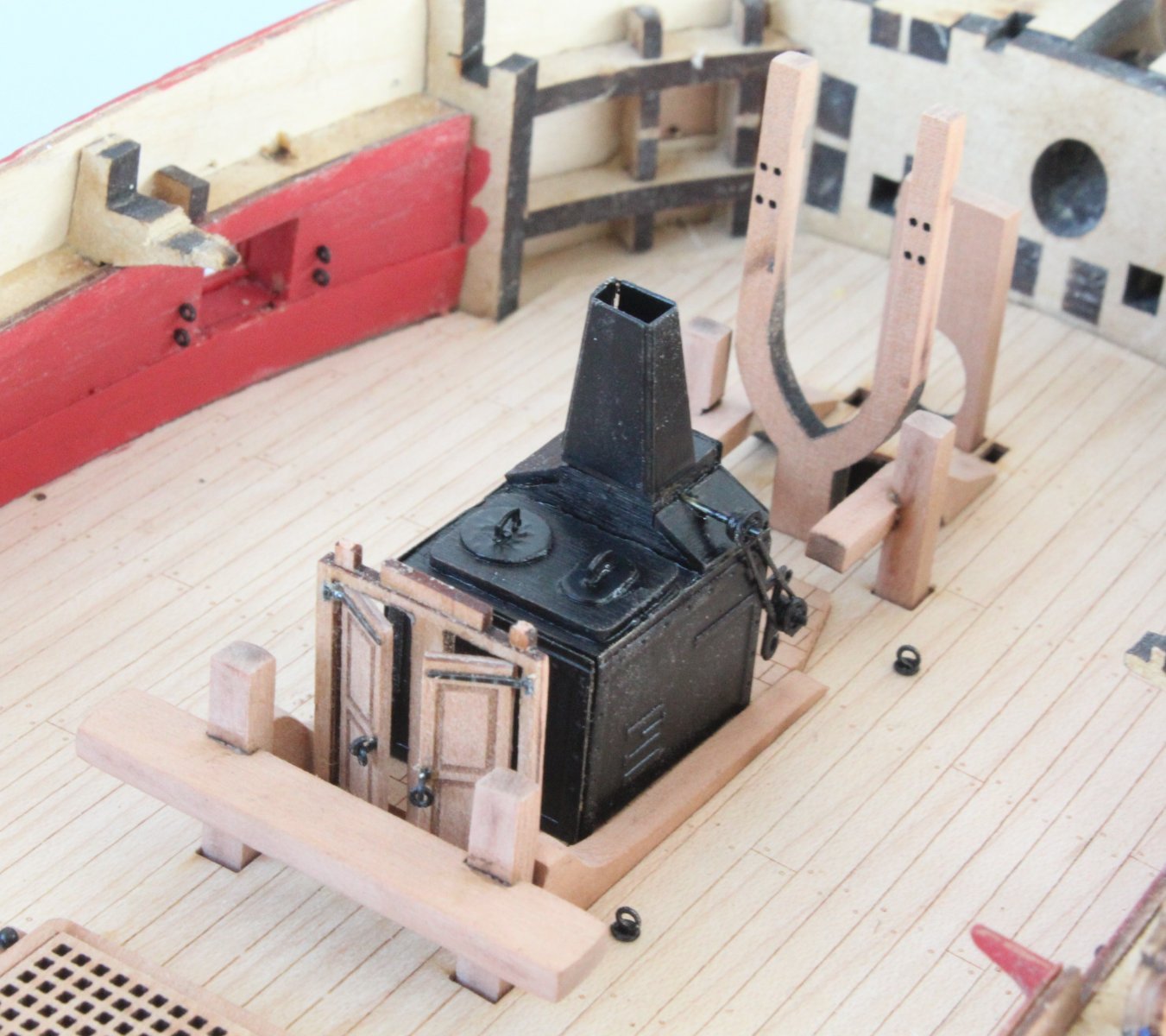
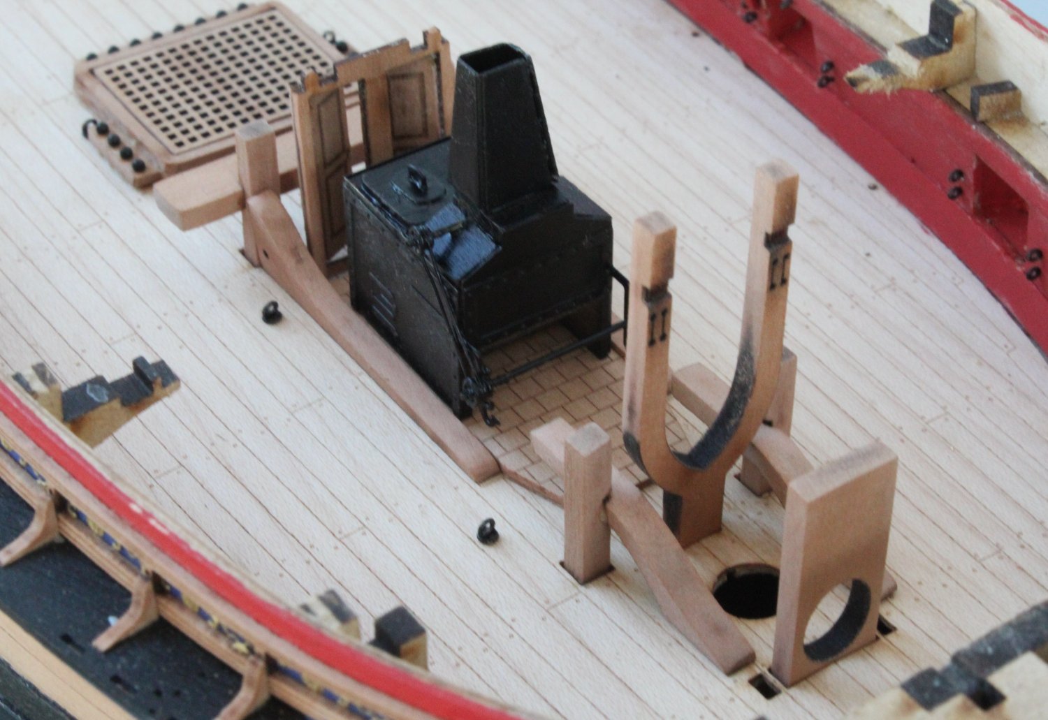
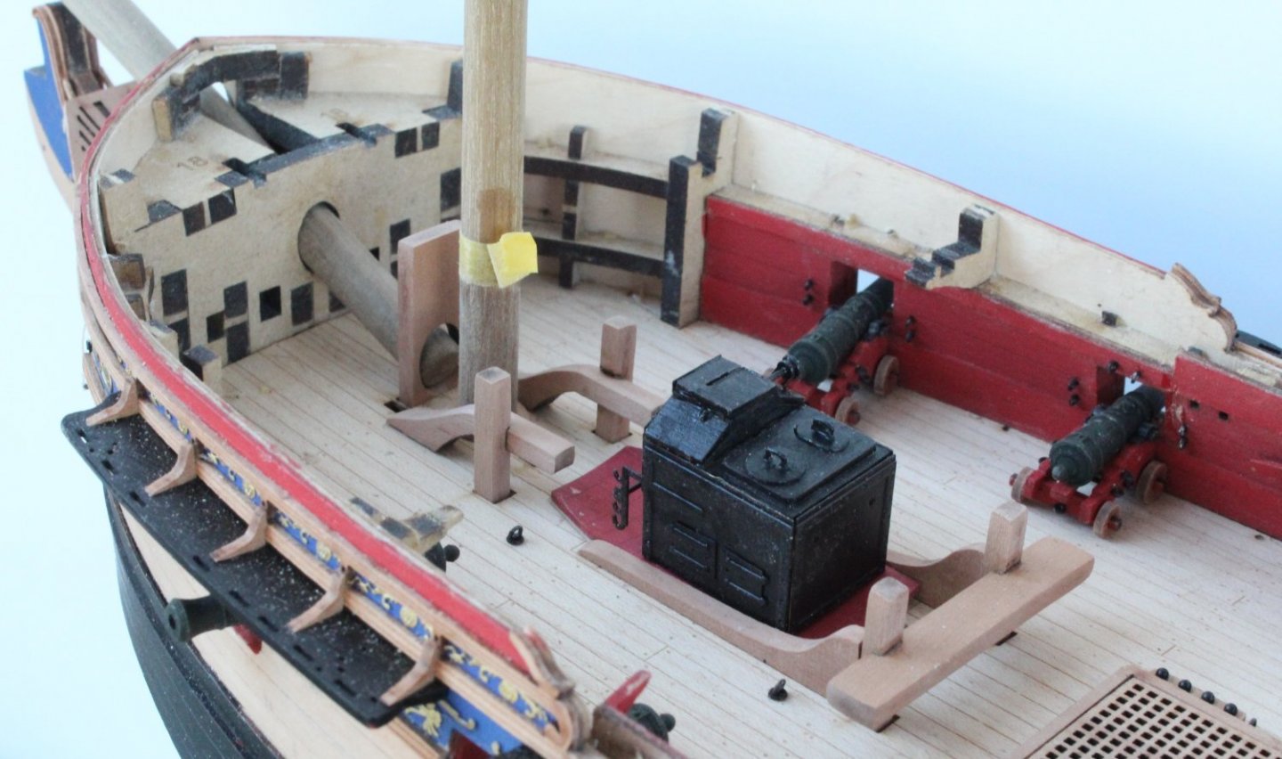
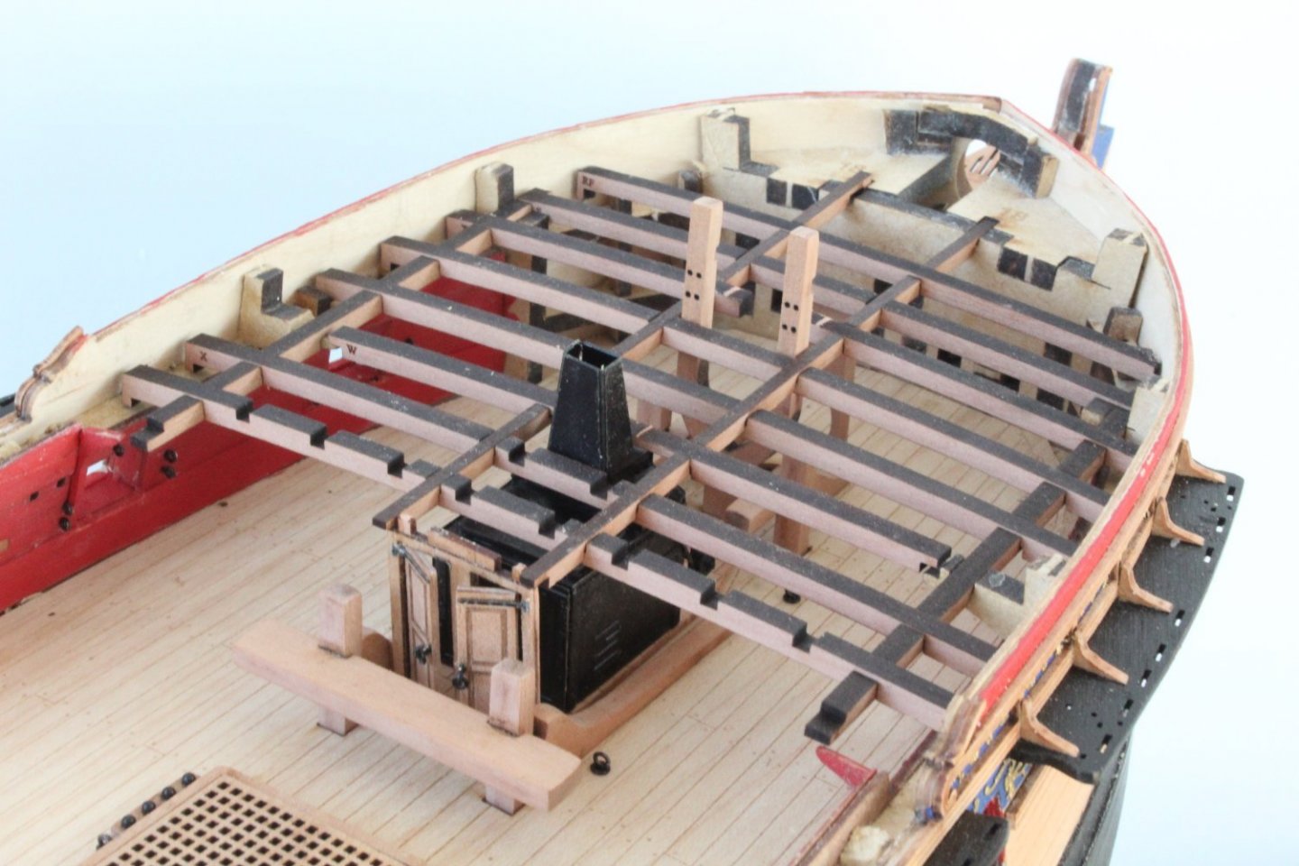
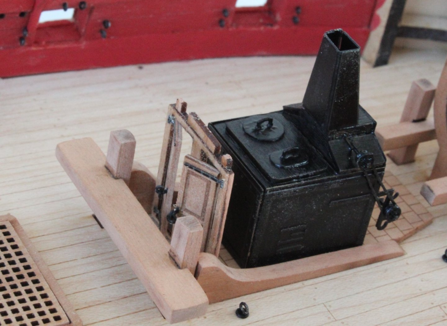
Bow Area Deck Items I have completed the basic assembly work on the gundeck items required for the bow area, with the exception of the 8 remaining cannons. I started with removing the laser char from the aft ridings bitts posts and associated cross beam. Next I assembled the gallery door frame and gallery doors. I set the gallery doors slightly ajar when fitting them in the door frames. The stove was a nice little item to build comprising a wooden frame which is then encased with some PE parts. The chain pully is affixed to the stove with 2 lengths of brass rods. I used 0.8mm brass rods as the locating holes in the chain pully and chain pully inner & outer discs were much too small for a 1mm brass rod detailed in the build manual. Finally I removed the laser char from the ridding bitts knees. The items were then trial fitted to the deck, as shown in the photo below noting the wooden stove base still requires to be painted. Next I removed the laser char from the fore ridings bitts posts and supports, the bowsprit support and the fore jeer bitts. These items were then trial fitted. The following two photos show the bow area of the gundeck with the deck items all dry fitted. Before gluing the deck items in place I needed to check the forecastle deck support beams and carlings. It would seem everything is a good fit, noting I will need to remove the laser char from the top edges of the forecastle deck support beams and carlings.


- 476 replies
-
- 9
-
-
- sphinx
- vanguard models
- (and 1 more)
-
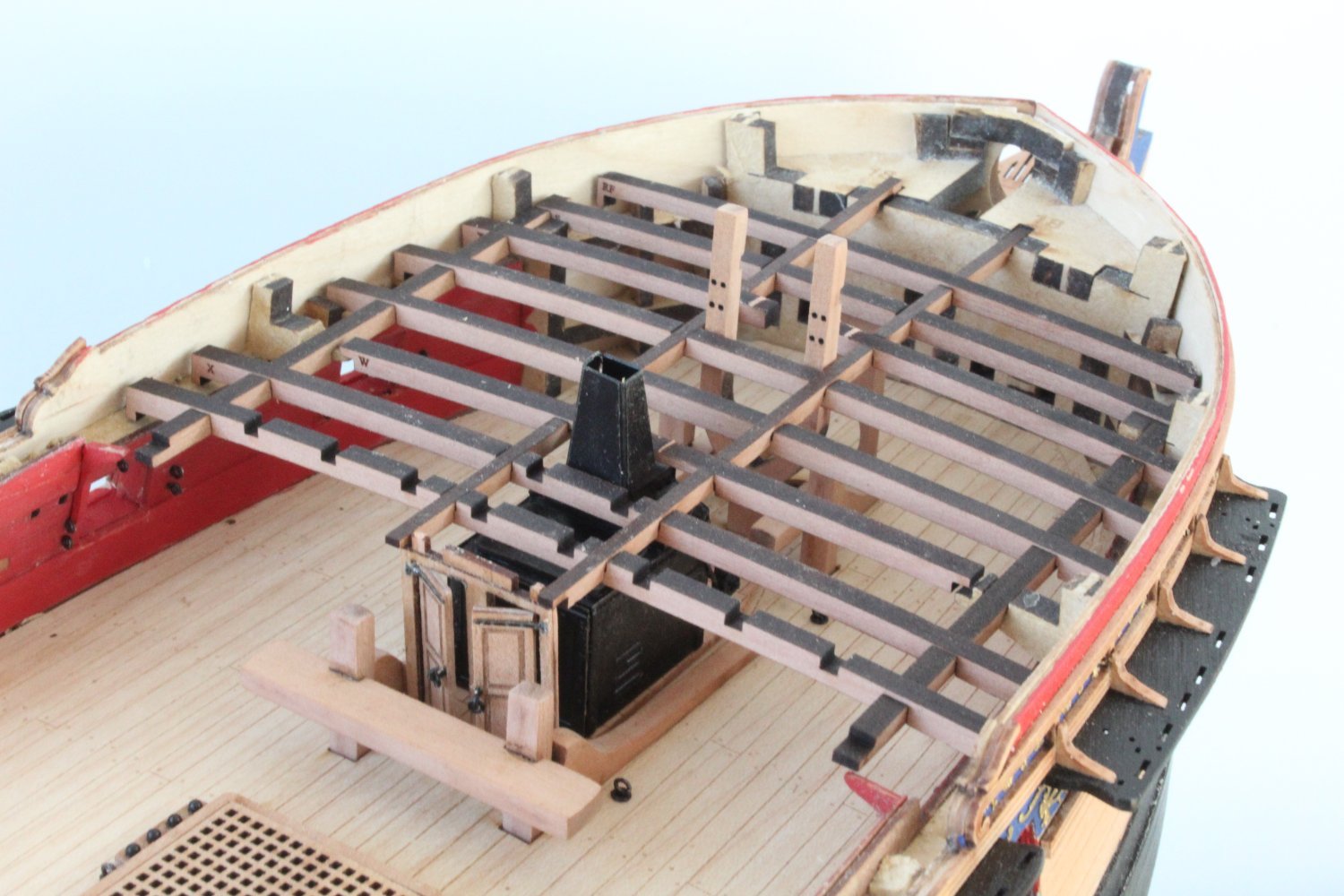
Quarterdeck Support Beams and Deck Items I started off by gluing the main mast support disc to the gun deck, the main mast dowel was used to check the position. I then did a trial fit of the chain pump assembly items. No problems were encountered. I completed the installation of the hanging knees for the midship walkway deck. Although not shown on the photo below I have also added the wooden cleats (2 per side). Now that everything has been trial fitted it was time to glue the various deck items in place. The final installation went very smoothly. The completed areas have been coated with a varnish / white spirit solution. The final three quarterdeck support beams when then added. The hand pump dowels are missing a coat of varnish, this will be added when the remain areas of the completed gundeck are varnished. The sphinx is ready to have the quarterdeck installed, but I will complete all the work on the gundeck before moving on the the quarterdeck work. I am now turning my attention to the deck items required for the bow section of the gun deck. I thought it would be prudent to recheck the bitts and foremast would still fully locate in the slots on the lower deck and thankfully everything still fits. I did a trial fit of the forecastle deck beams. I encountered a slight problem with the alignment of the two forecastle beam carlings when they were fully engaged in their respective locating slot, I had no such issue with my V1 build. I believe I have a solution to the problem but I will put on the back burner until after I have completed adding the remaining gun deck items, as this will help ensure the deck beams are correctly positioned. My next task will be building the following items: a) Galley stove b) Galley doors c) final 8 cannons


- 476 replies
-
- 10
-
-
- sphinx
- vanguard models
- (and 1 more)
-
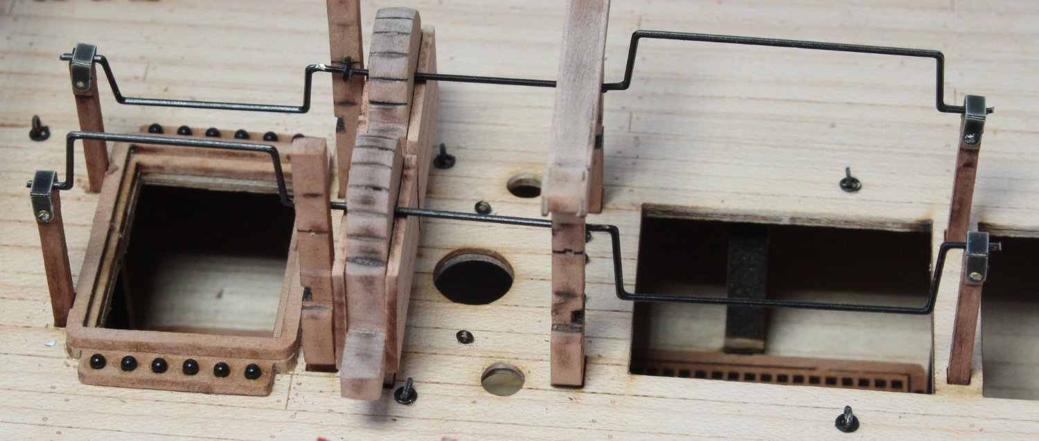
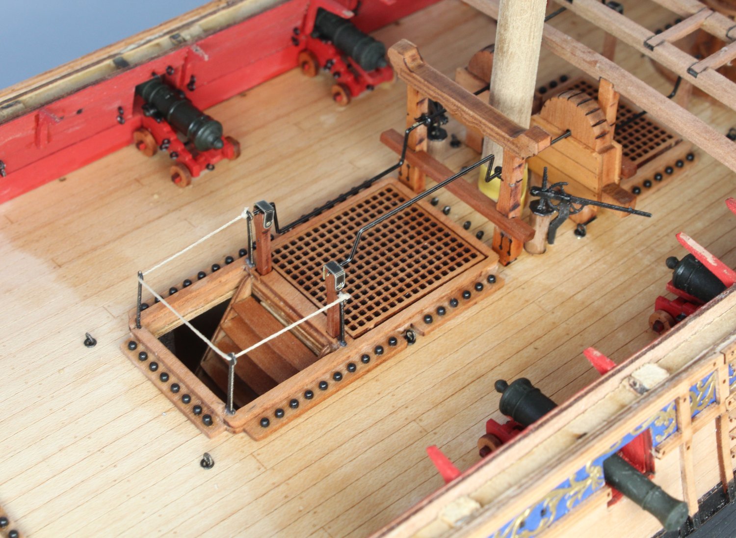
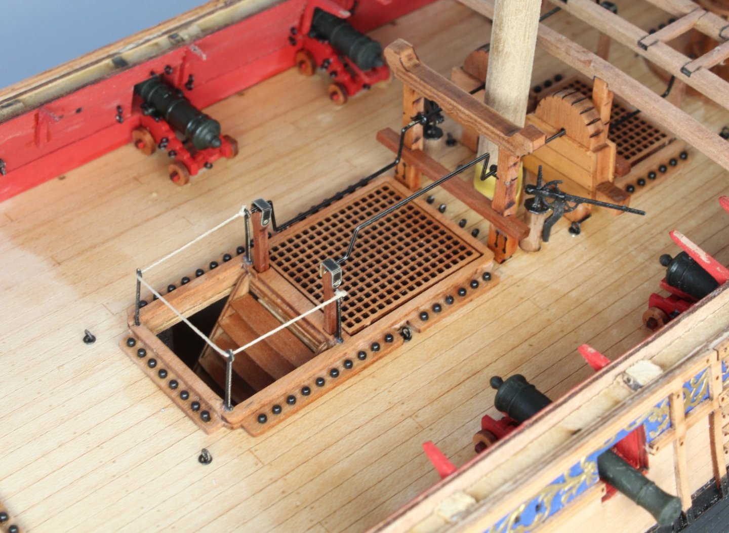
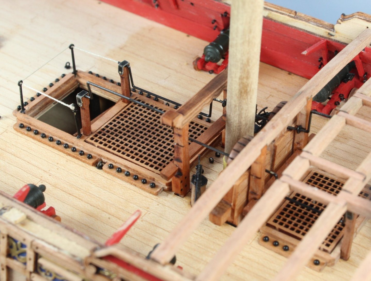
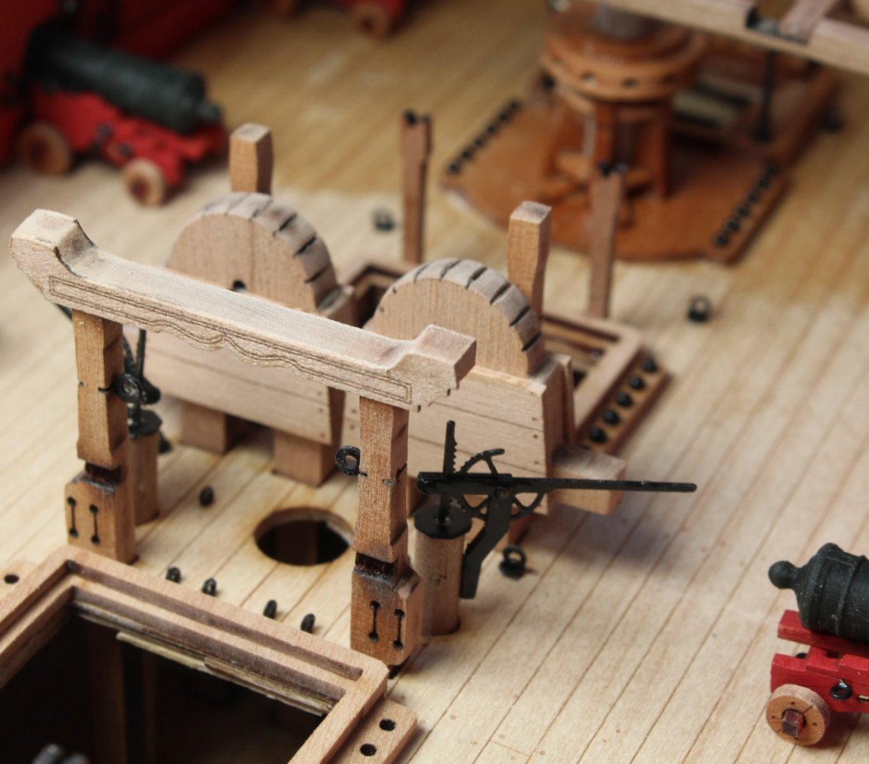
Deck Items Work In Progres. When working on the V1 build I did find fitting the walkway hanging knees after the deck items had been installed a little troublesome. Therefore I will fit the knees before the deck items have been fitted. The various knees have been removed from the wooden sheet and the laser char removed, the parts will now be painted red before fitting. I have also continued to work on installing the quarterdeck support beams. The aft hatch and associated parts (cannons, capstan, pawls, cannon balls, aft ladder and stanchions rigged with 0.5mm natural thread) were fitted prior to fitting the beams above them. I have also dry fitted the midship deck items, as can be seen in the photo below. The chain pump handle bars (fore and aft) and end caps are currently in the paint shop. They have been given a spray with a primer and I'm now waiting for the second coat of black paint to fully dry before they are test fitted. I have not test fitted the cross members to the bitts but will be doing so.


- 476 replies
-
- 13
-
-
- sphinx
- vanguard models
- (and 1 more)
-
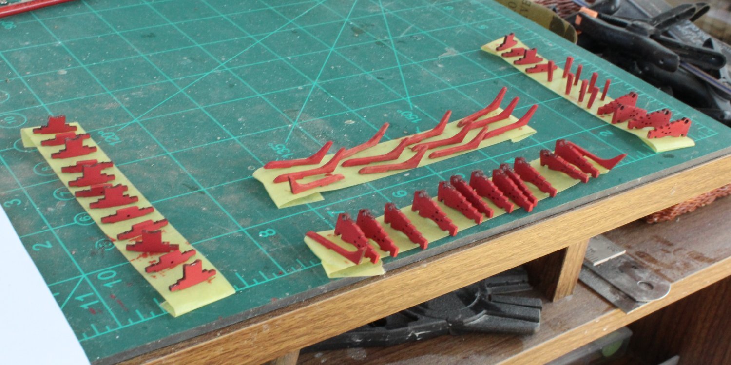
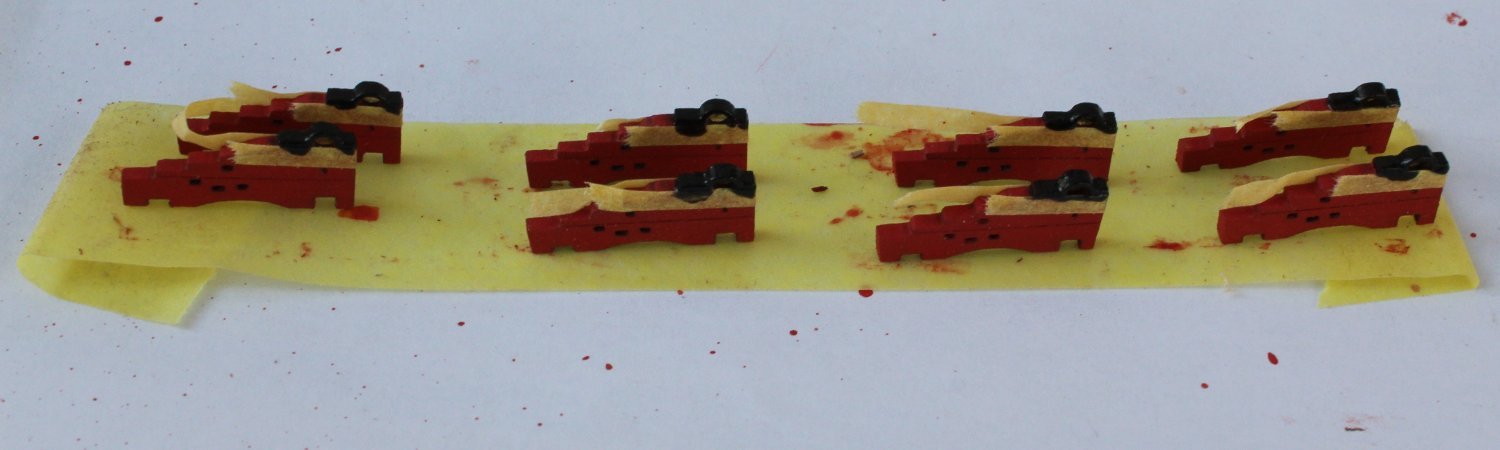
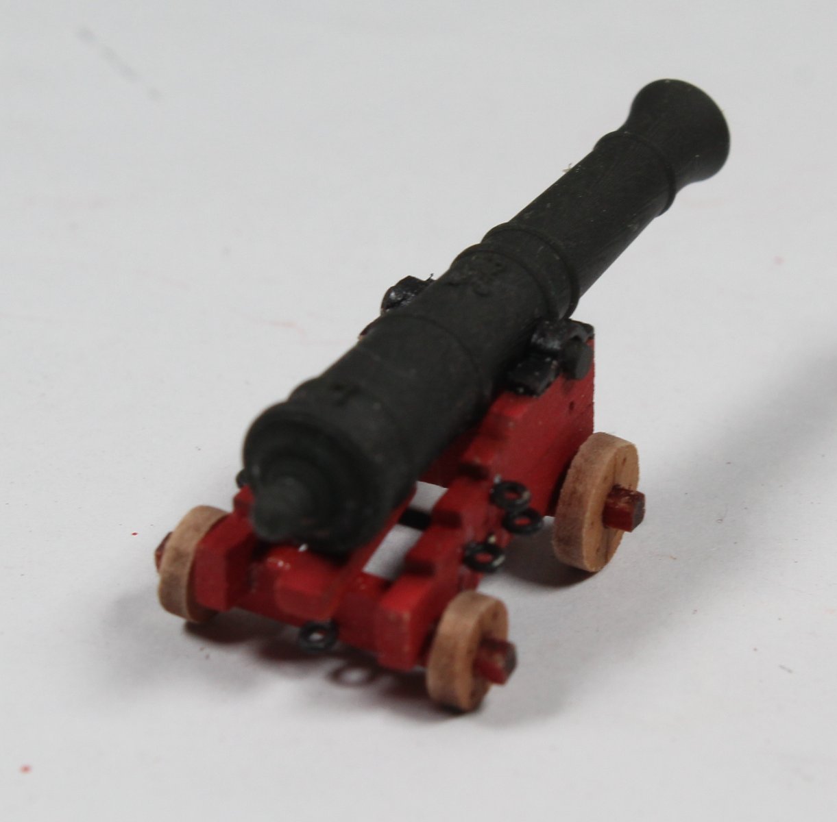
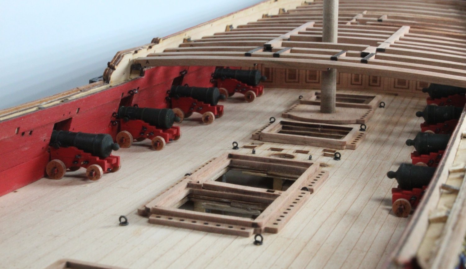
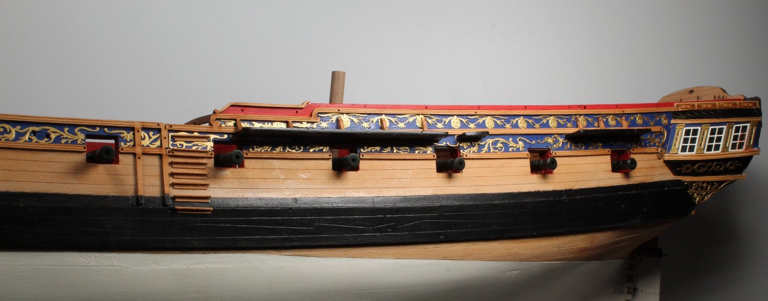
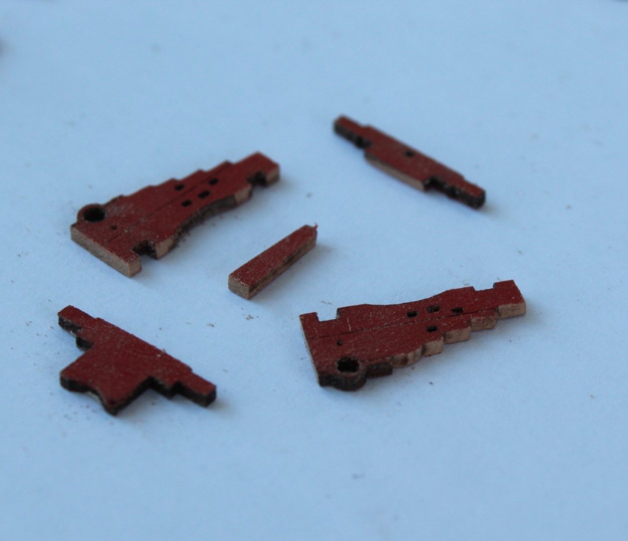
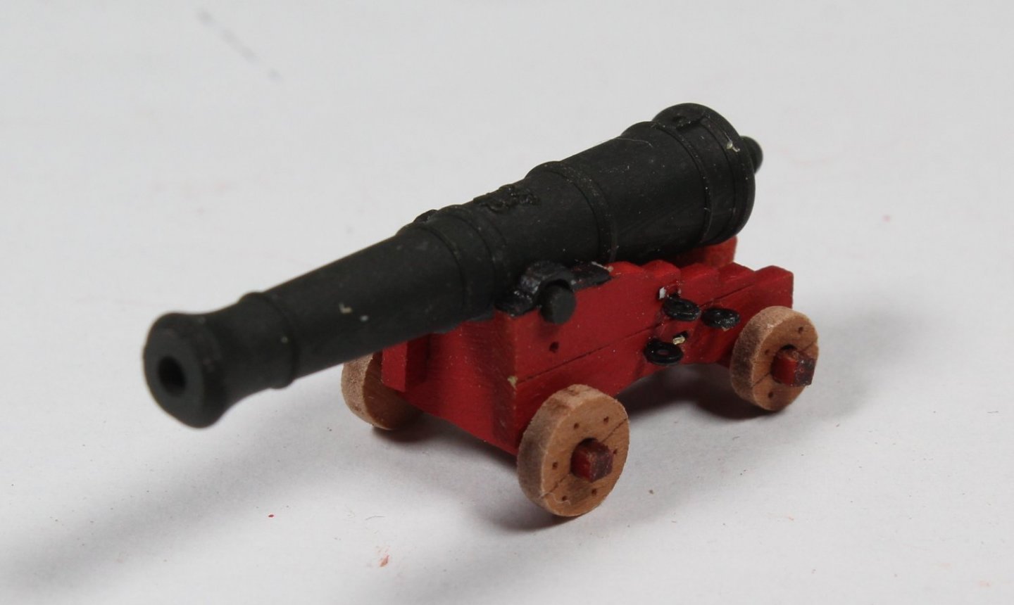
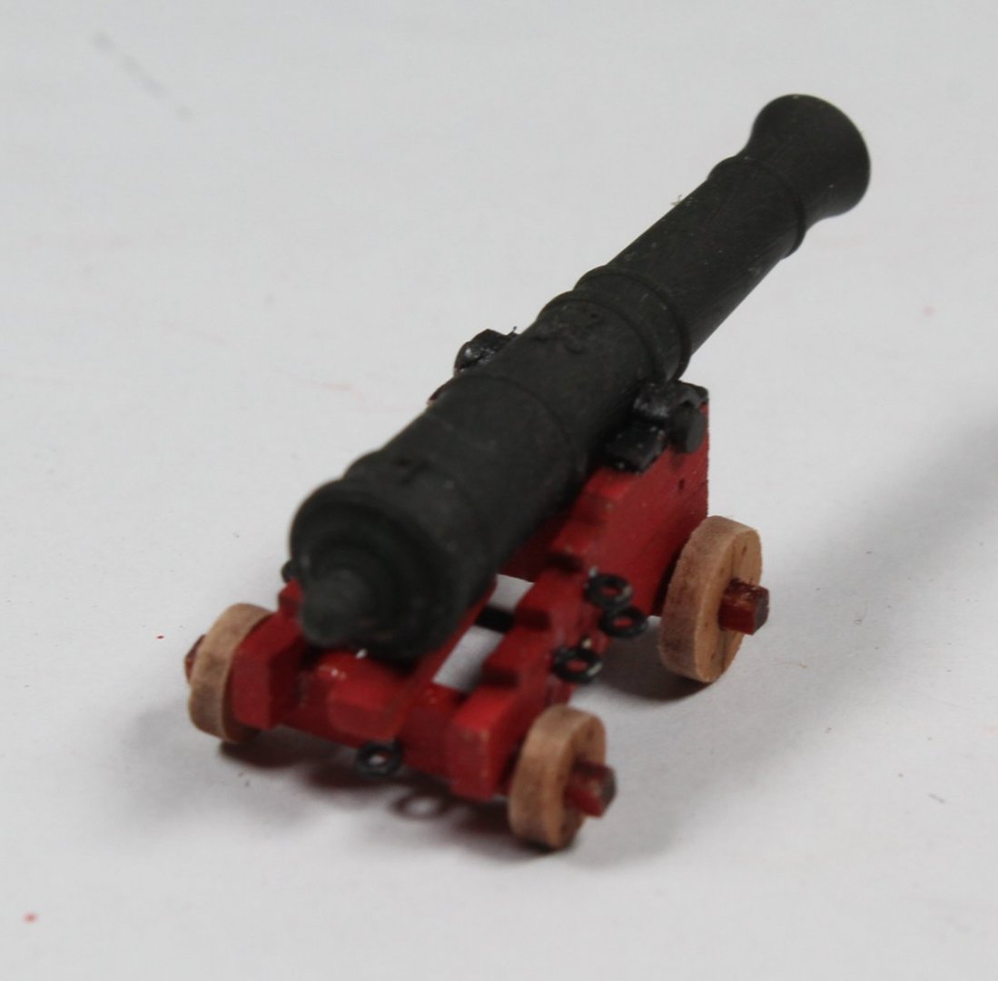
8 More Cannon Built, 8 more left to build The various wooden cannon parts were removed from the wooden sheet, along with the remaining hanging knees. I have already primed and painted all the PE parts which will be cut from the PE sheets when required to be added. With regard to the wheels I had a light bulb moment to remove the laser char. I placed some cannon wheels on a metal rod and wrapped some tape on either side to keep the wheels in place. I then used my rotary (dremel like) tool with a sanding head fitted. When the rotating head was placed on the wheels they spun around and the laser char was removed. The wheel retained their circular shape. It is not a perfect method but it is so much better and quicker compared with using a sanding sticks and sandpaper. The next task was to remove the laser char from the various edges of the cannon sides and hanging knees. I used a narrow Florry sanding stick for this task. It was then time to paint the cannon parts and the hanging knees. The following photo was taken after the first coat of paint had been applied. Once the paint had dried I did apply a second coat. Using some 2mm tape the cannons were masked so the integral end caps could be painted black. With all the wooden parts prepared the basic cannon frames were assembled. The two axles were glued to the left hand side. Once the glue had time to grip the cannon was added, checking the emblem was face up.The right hand cannon side was then glued in place. Once I had allowed time for the glue to cure the eyebolts and cross beam PE parts, the wooded quoins and wheels were added to complete the task. To finish of this post I dry fitted the completed cannons to the gun deck. I did start to sand the bottom edge of the coamings so they follow the curve of the gundeck for a better fit, a little bit more is still required. The cannons are ready to fire a broadside when required. I must remember to paint the top side step blue and bottom two side steps black.


- 476 replies
-
- 10
-
-
- sphinx
- vanguard models
- (and 1 more)
-
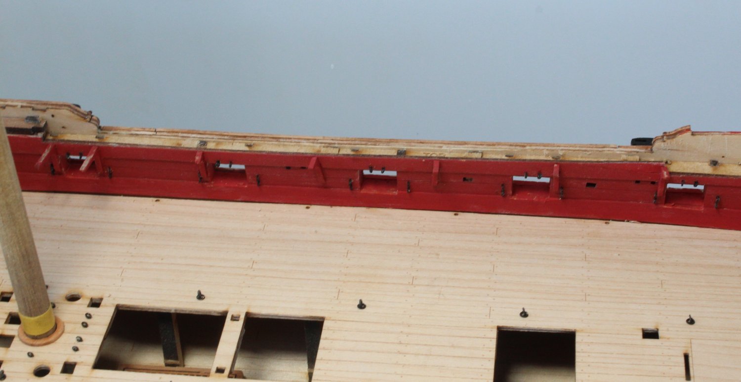
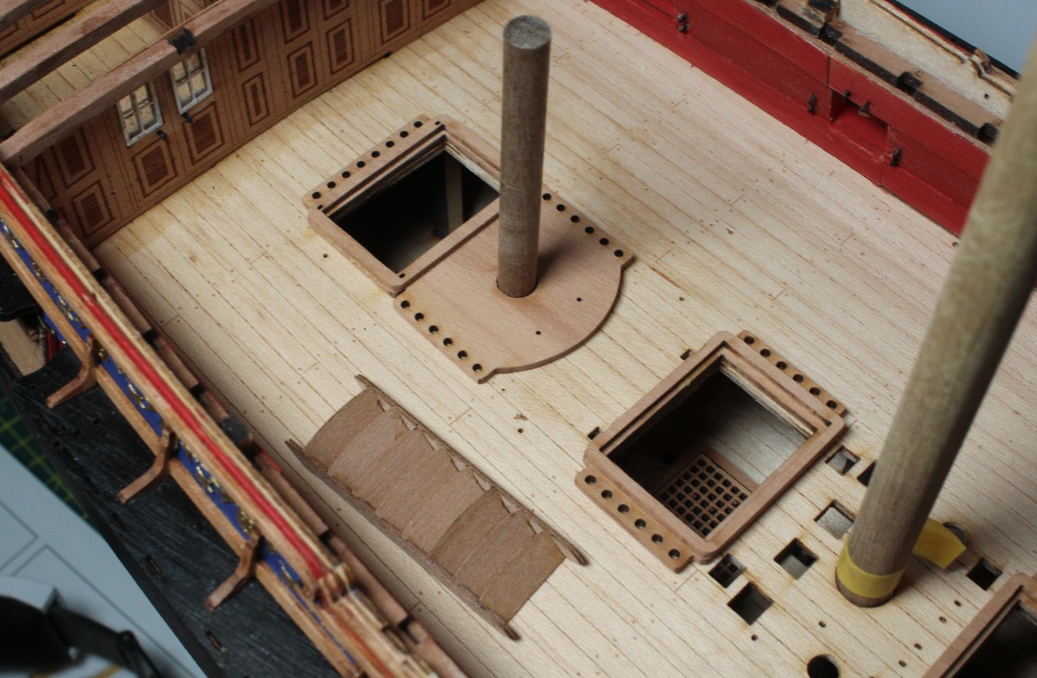
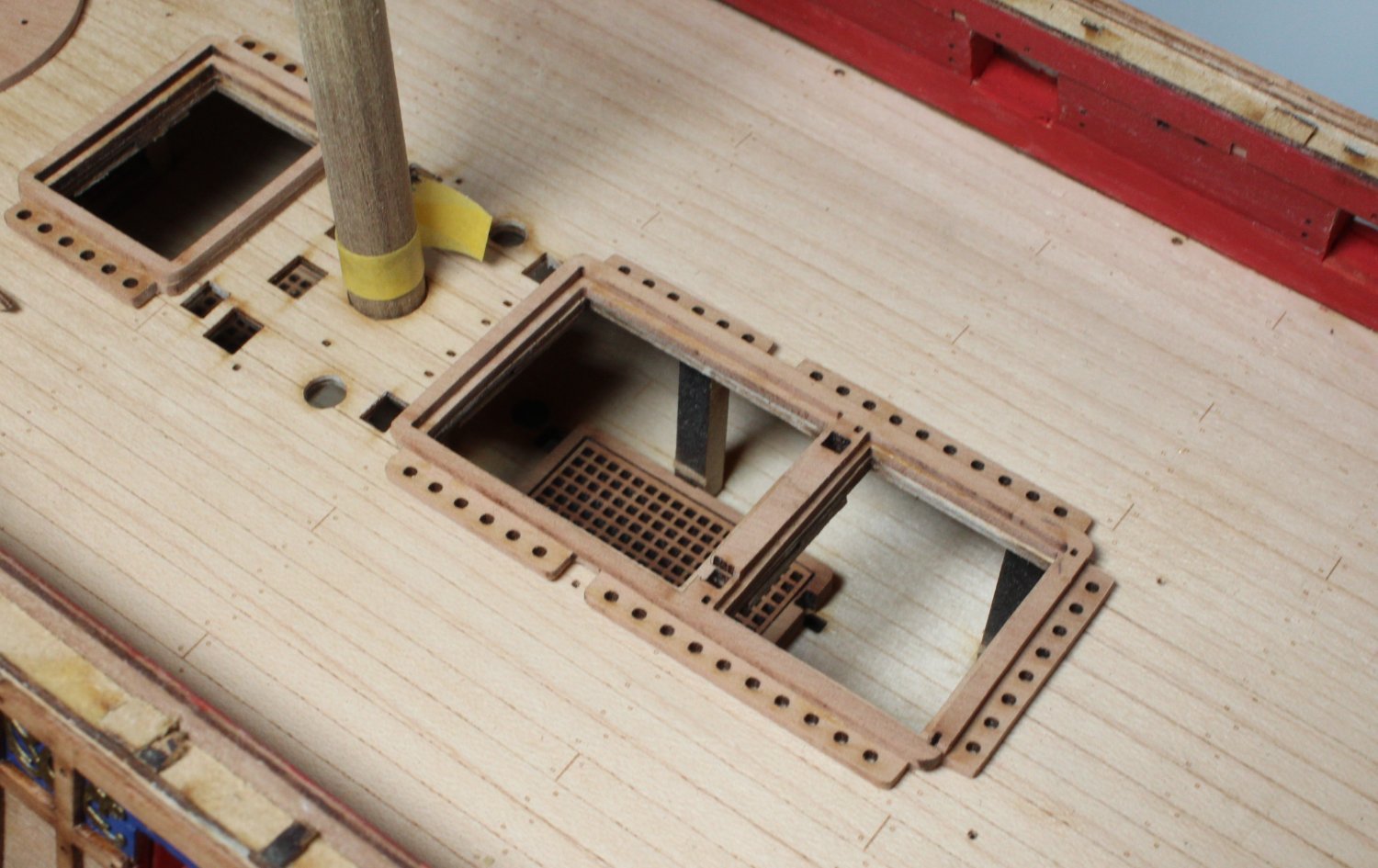
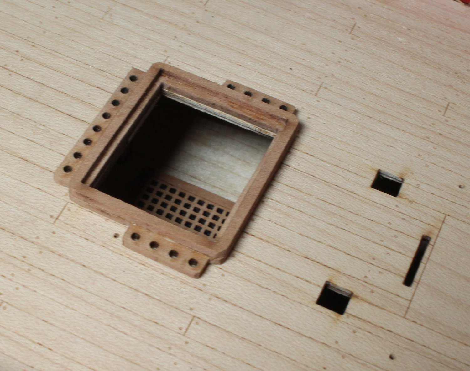
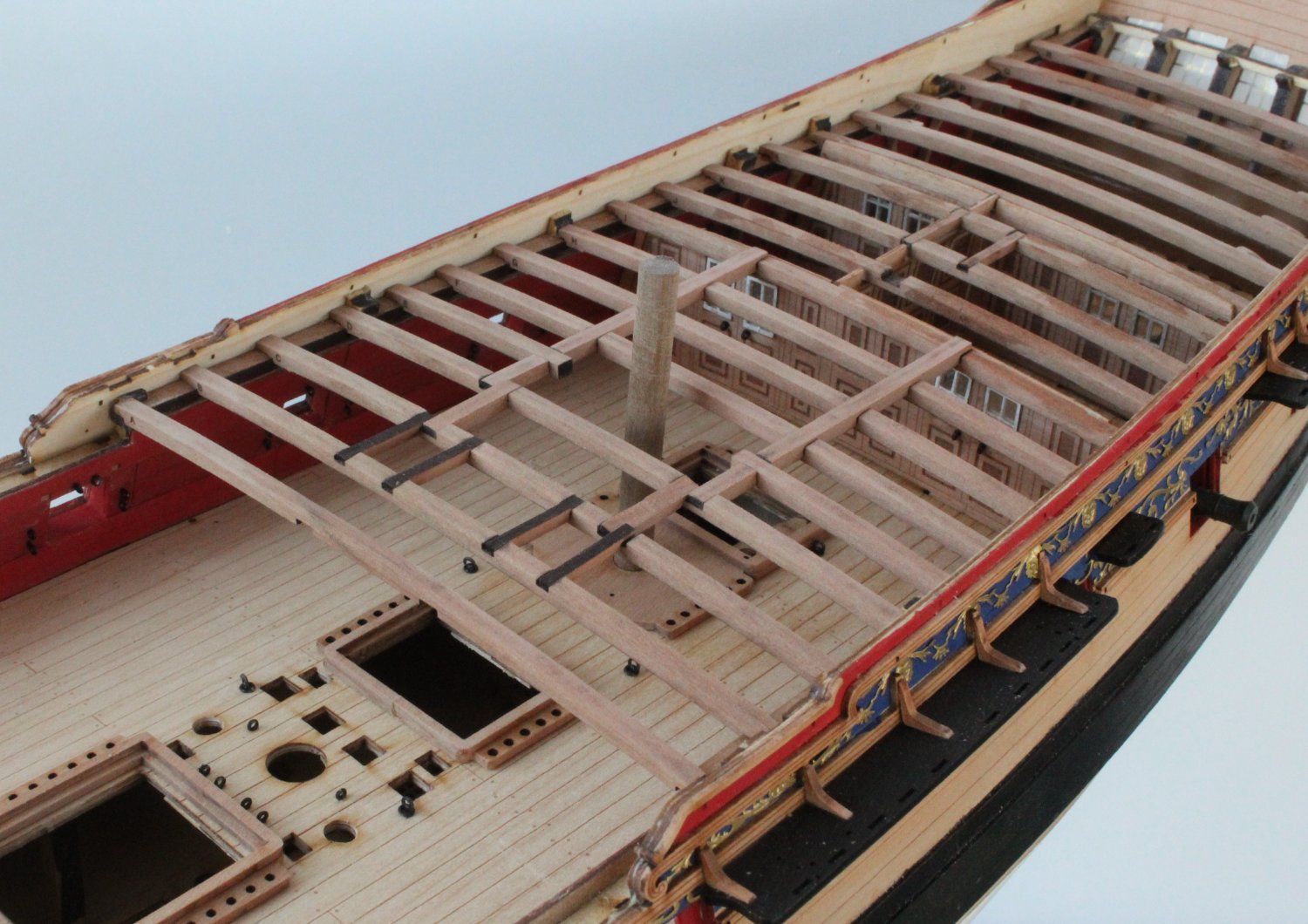
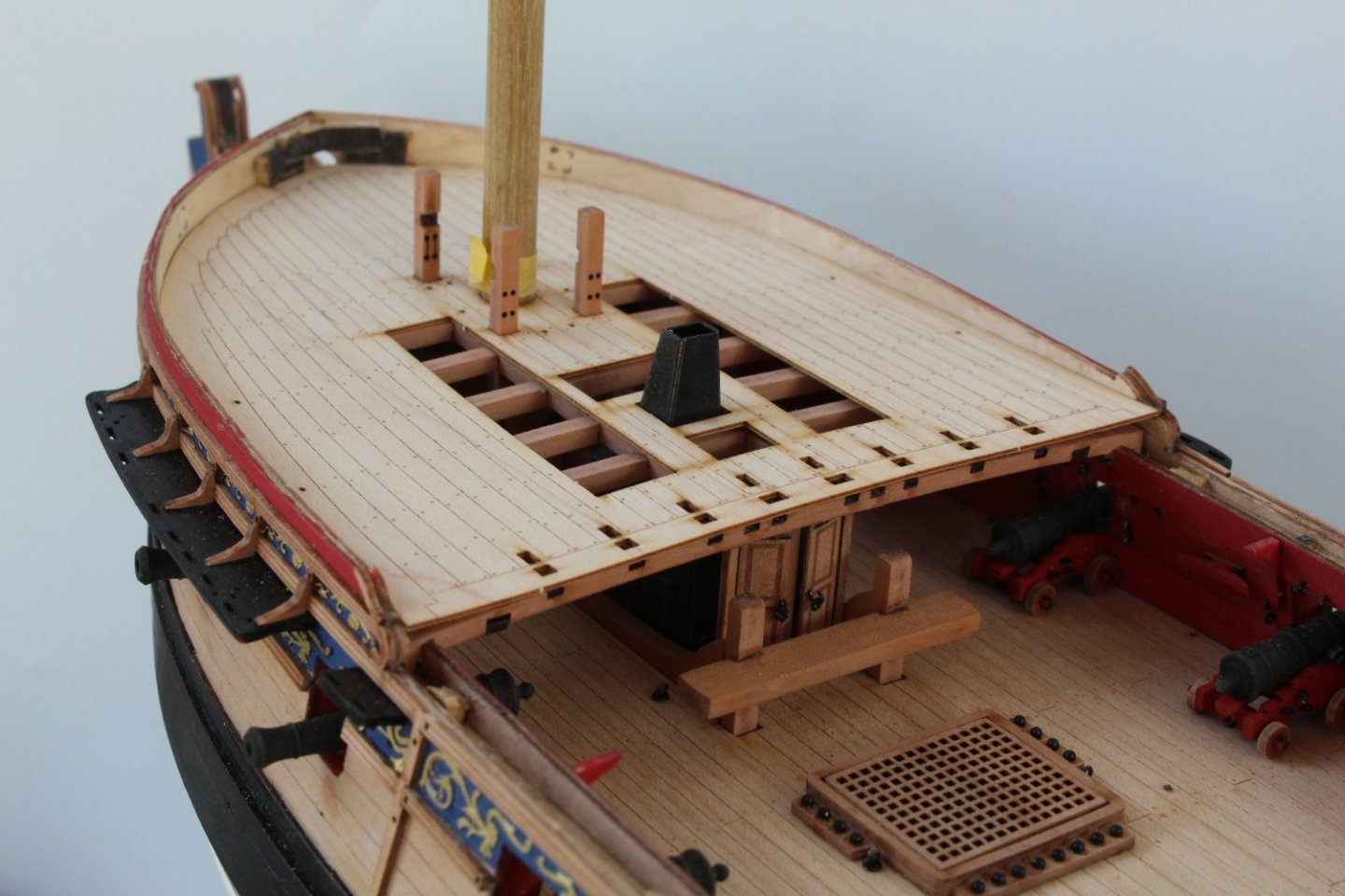
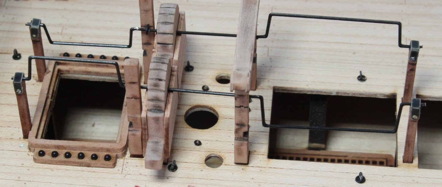
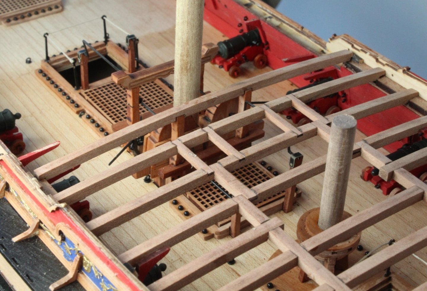
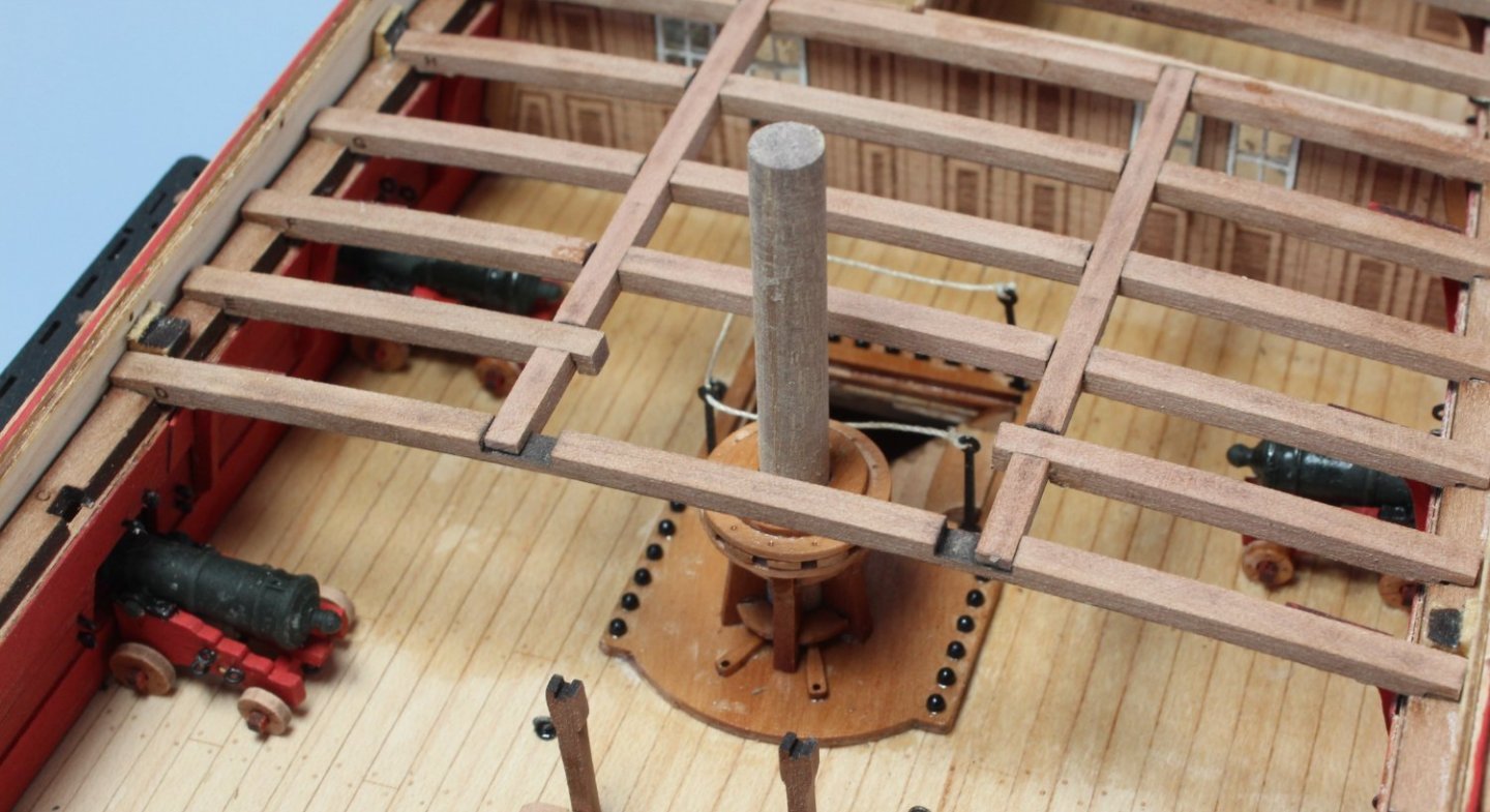
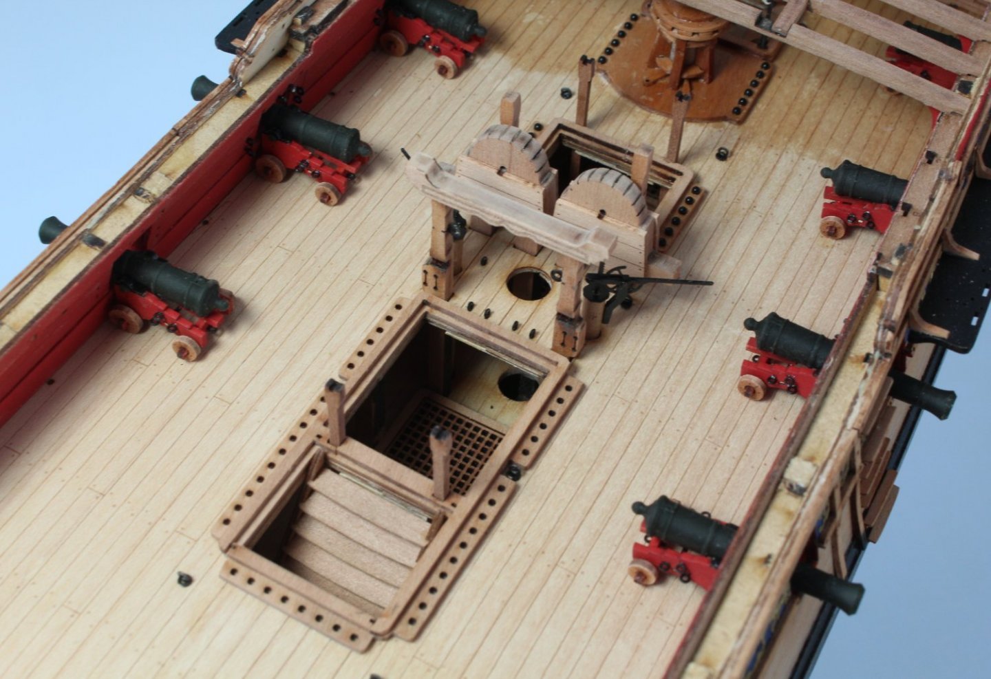
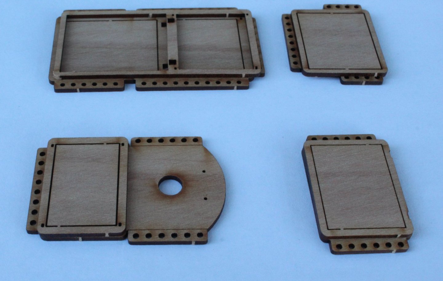
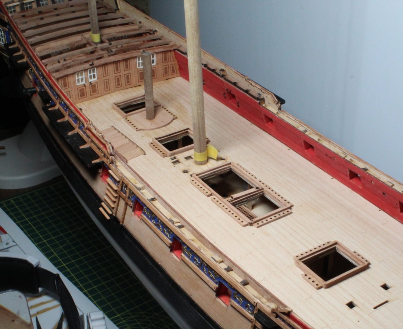
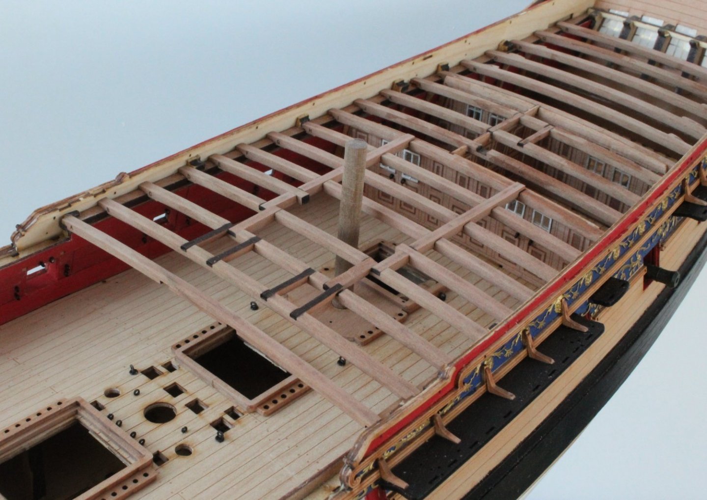
Gun Deck Coamings I thought I would start this post with a couple of photos of the current state of play with the V2 build. With the first photo I have added some dowels to check the mizzen, main and foremast are properly inserted fully in their respective locating slots The next photo shows the current progress with fitting the quarterdeck support beams. Before I can go ahead and fit the remaining quarterdeck support beams I need to assemble and fit the various deck items which sit beneath the quarter deck. The first items to consider are the coamings and aft ladder. The coaming parts, removed from their sheets, waiting for the laser char to be removed before the parts are glued together The aft ladder parts ready to be assembled, noting the laser char will be removed from the leading edge of the rungs before the assembly. The various assembled coamings are dry fitted to the hull, the aft ladder is also ready to be fitted. Close up of the aft coaming with a dowel fitted ready for the capstan. The mid ship coamings The coaming closest to the bow The next job was to add the deck eyebolts and rings, the coamings are still only dry fitted. I have also dry fitted the aft ladder I am currently building 8 more cannons, so as I was waiting for some paint to dry I decided to dry fit of the remaining quarterdeck support beams. The first photo you will note I have not added the longitudinal support beams With the longitudinal support beams added, noting I have not, as yet, removed the laser char from the top edges of 4 support beams.


- 476 replies
-
- 9
-
-
- sphinx
- vanguard models
- (and 1 more)
-
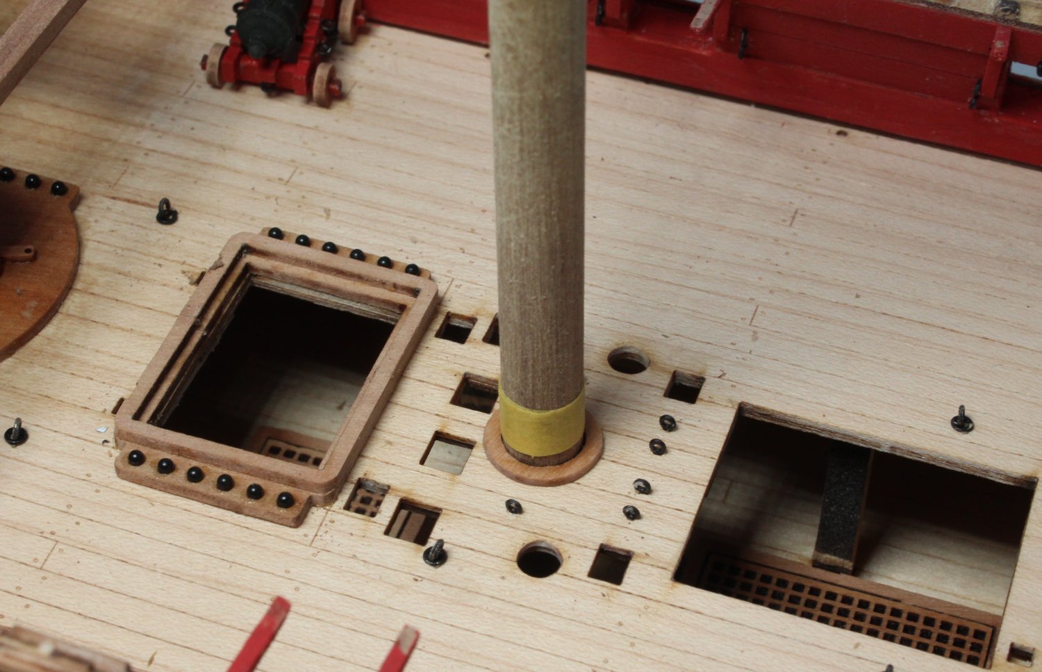
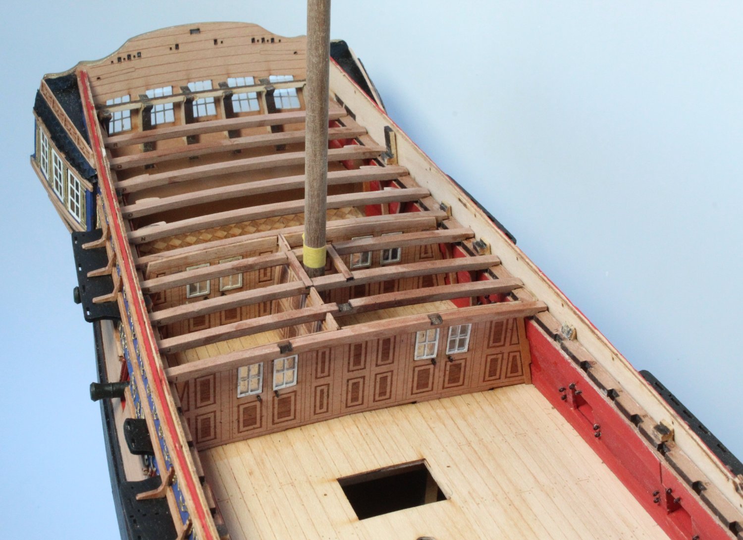
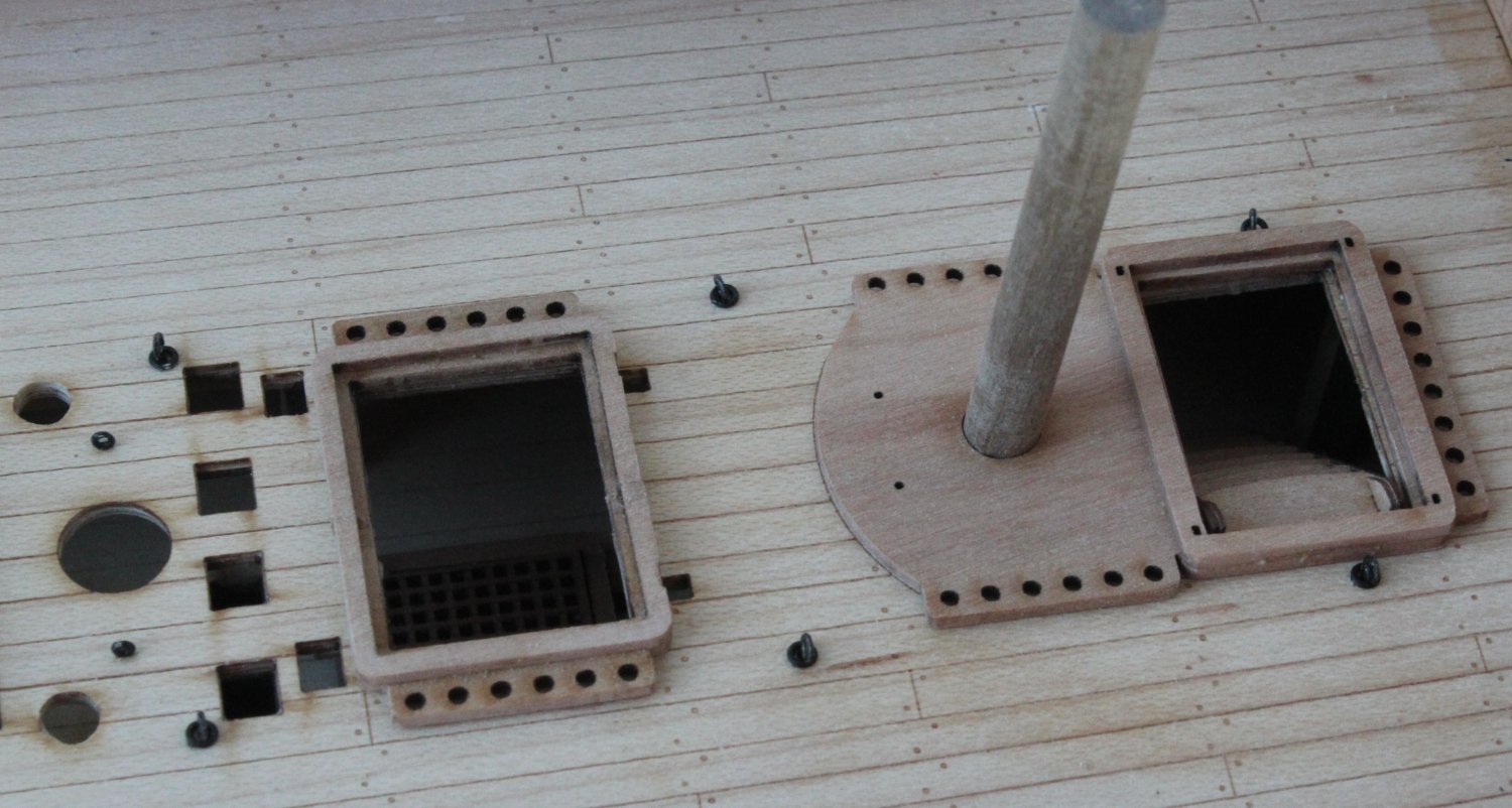
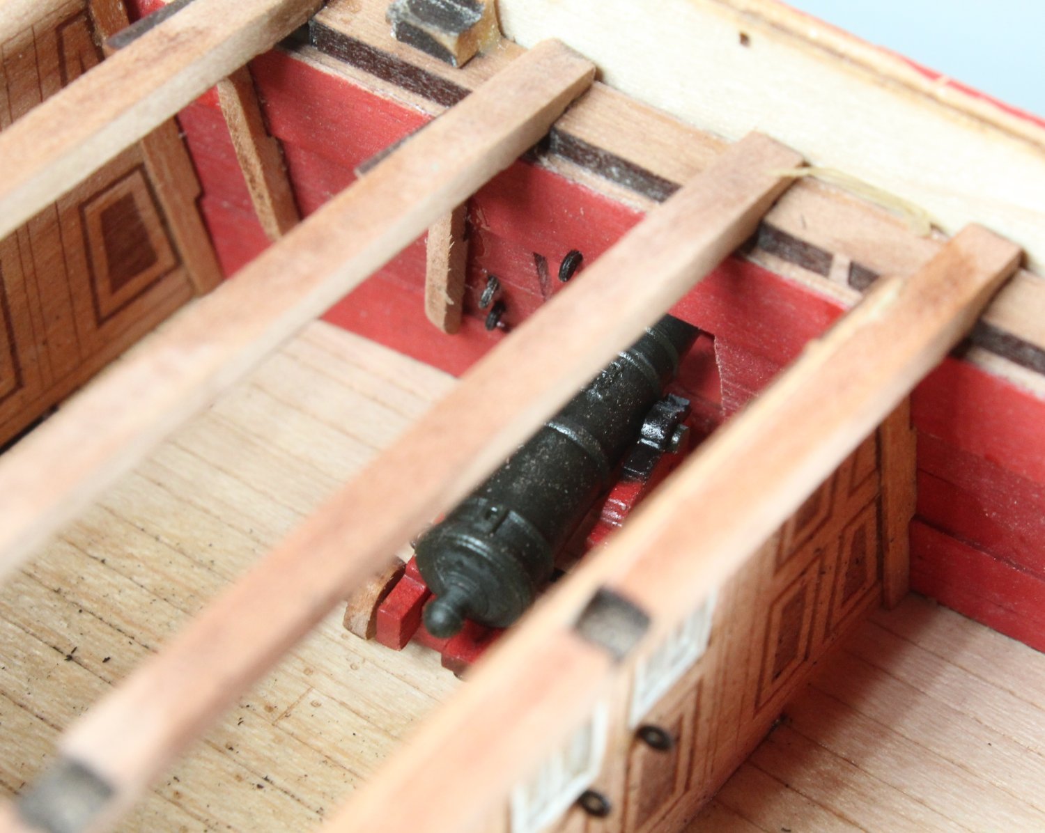
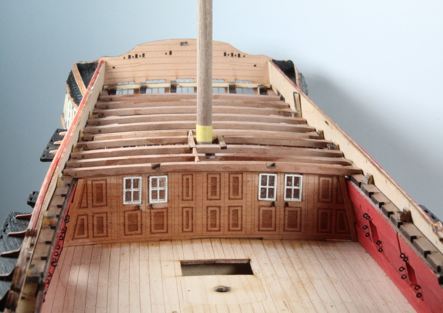
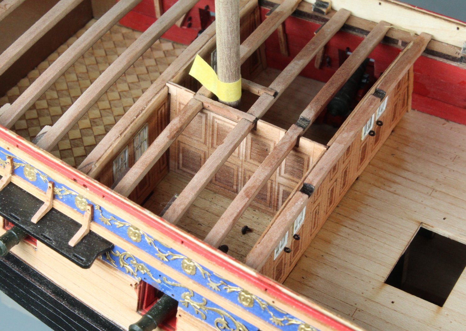
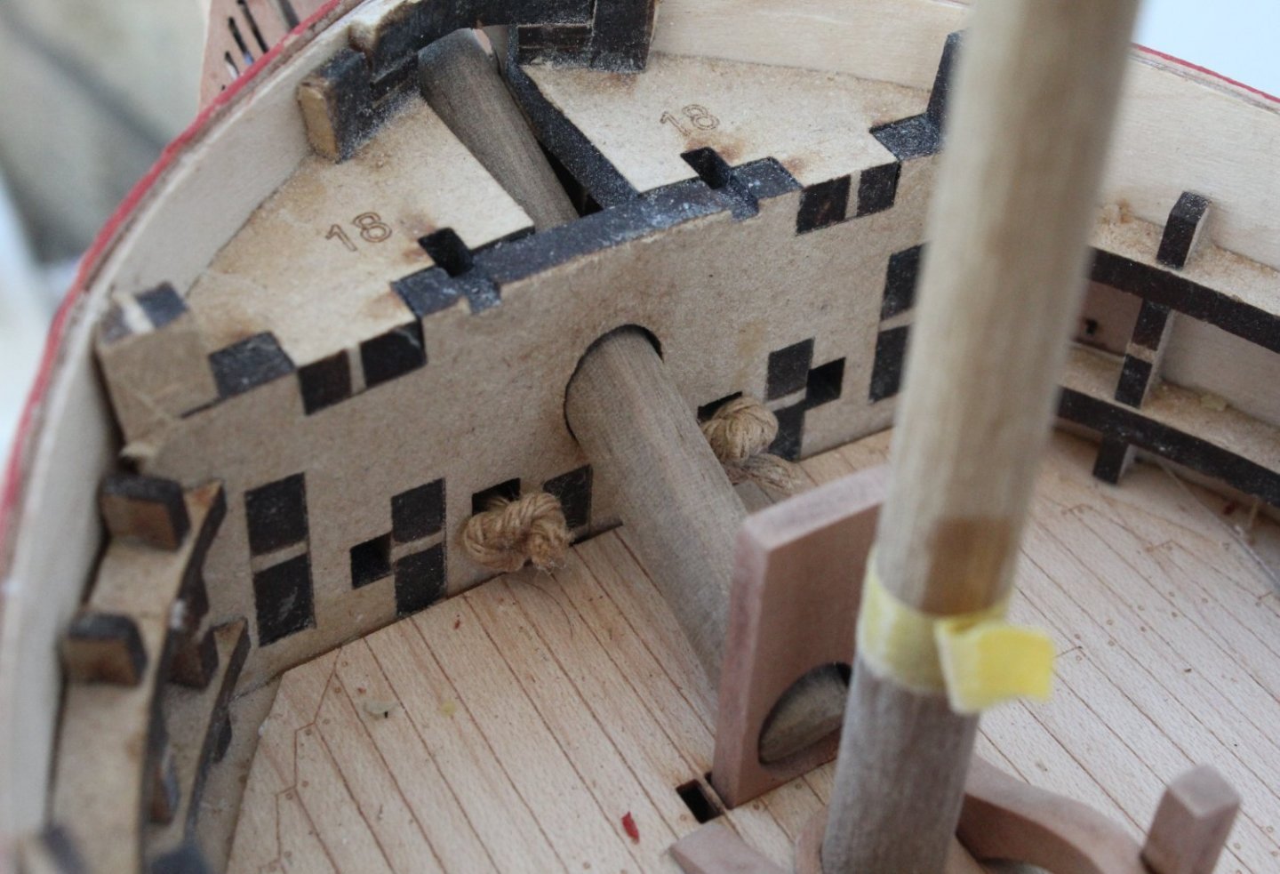
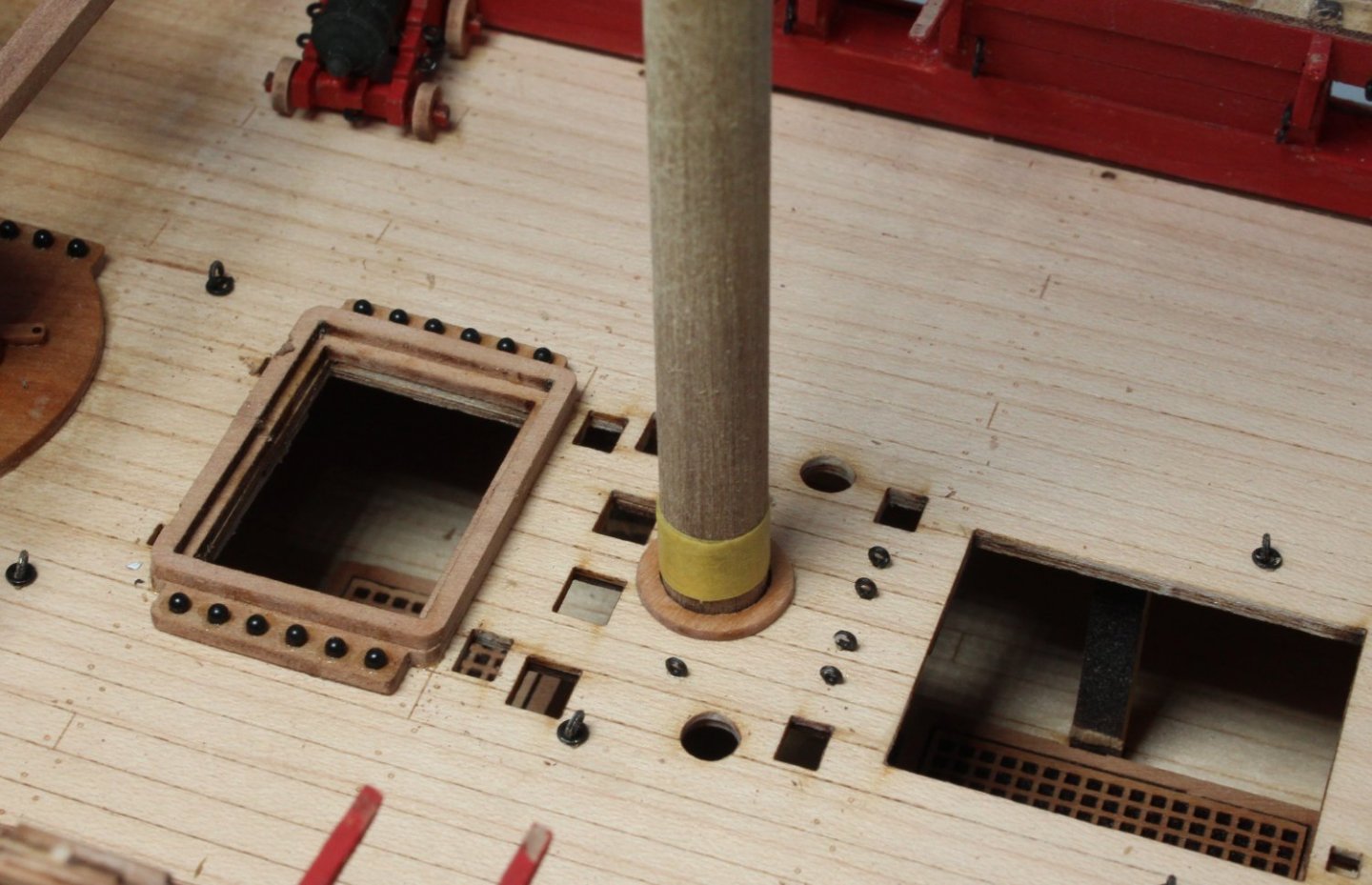
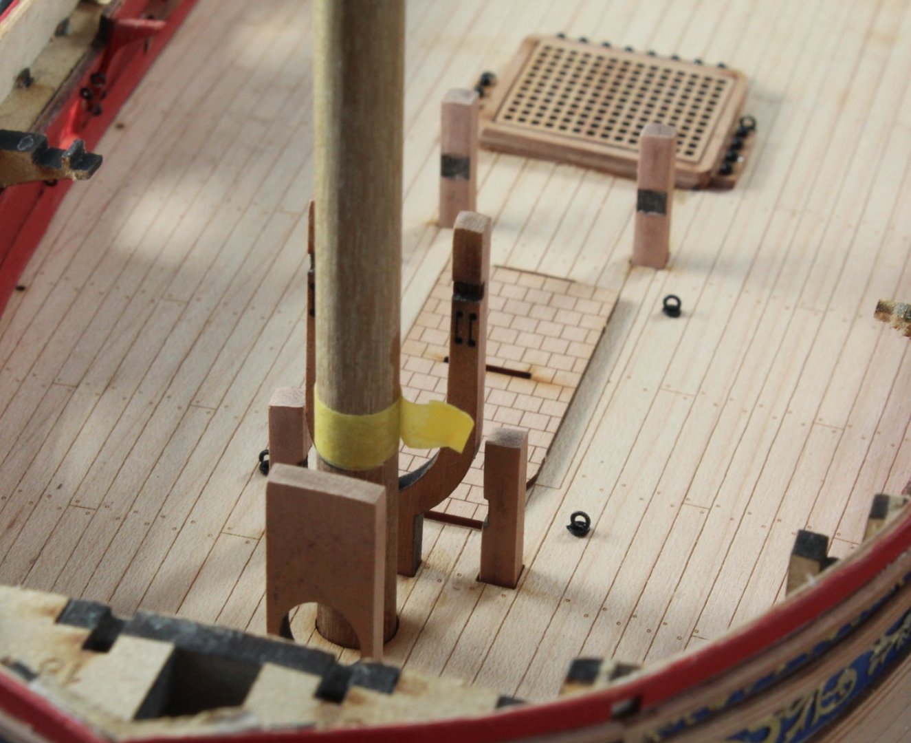
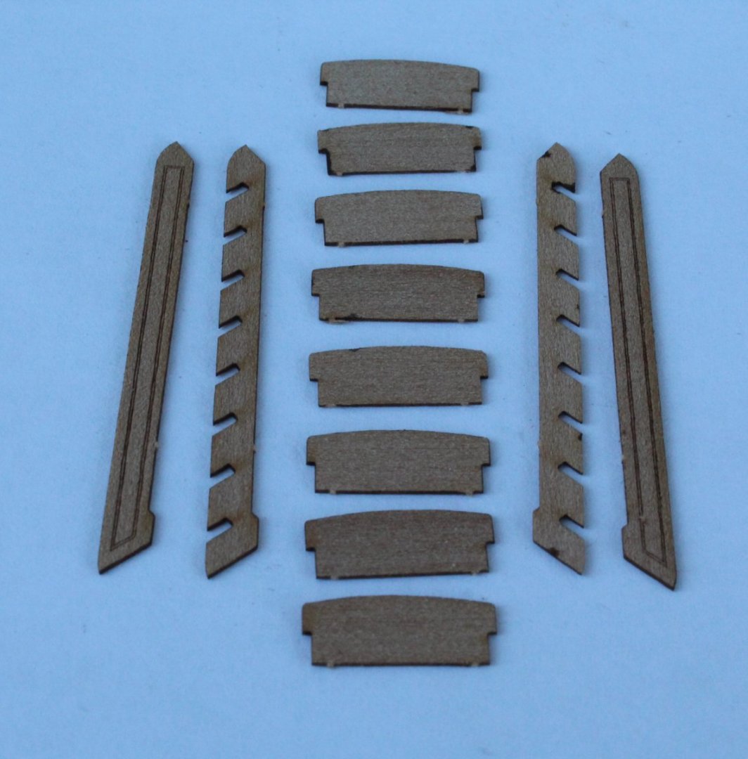
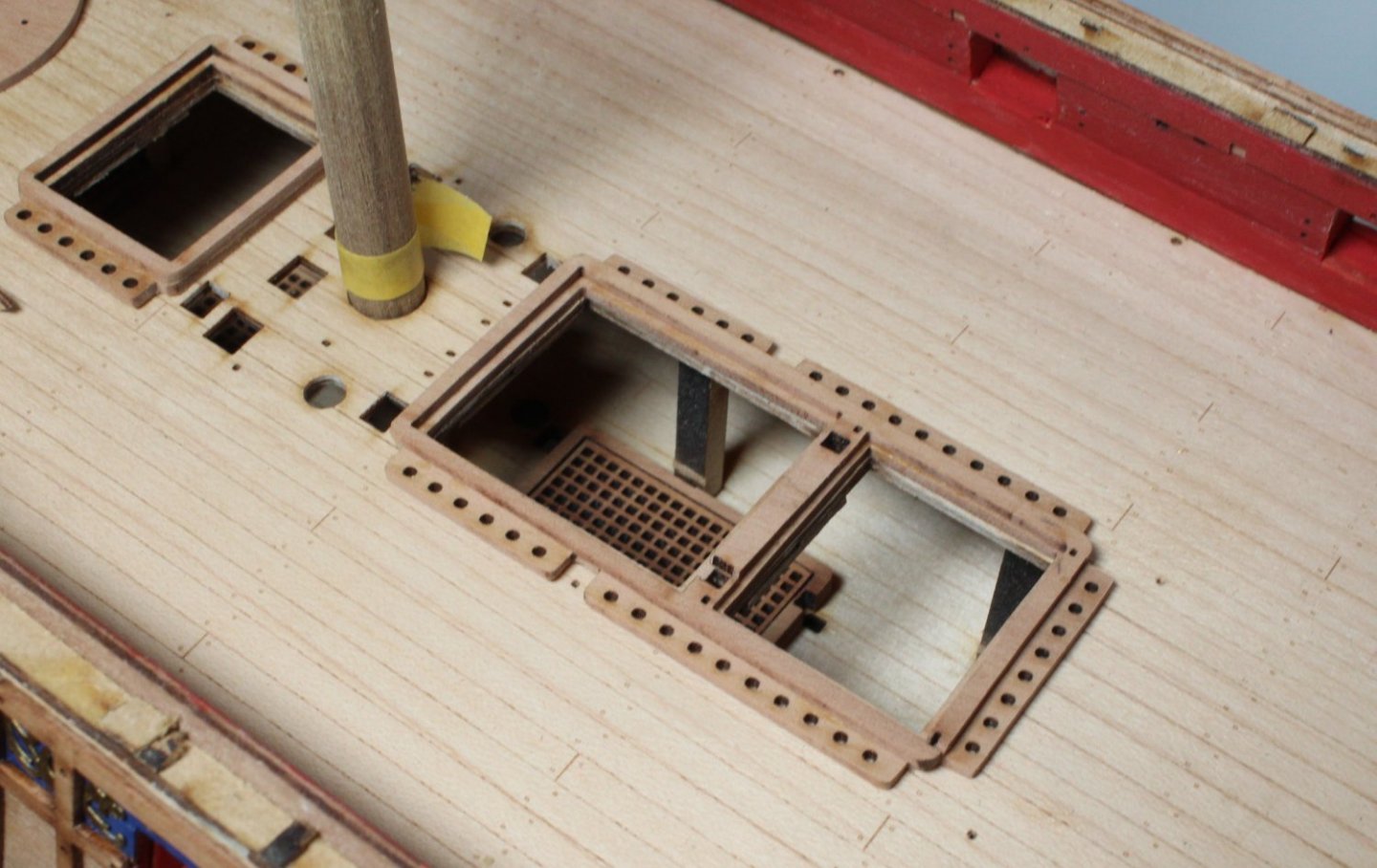
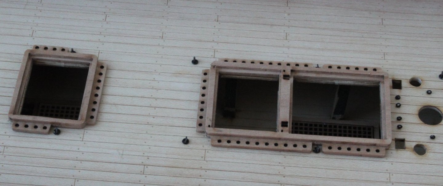
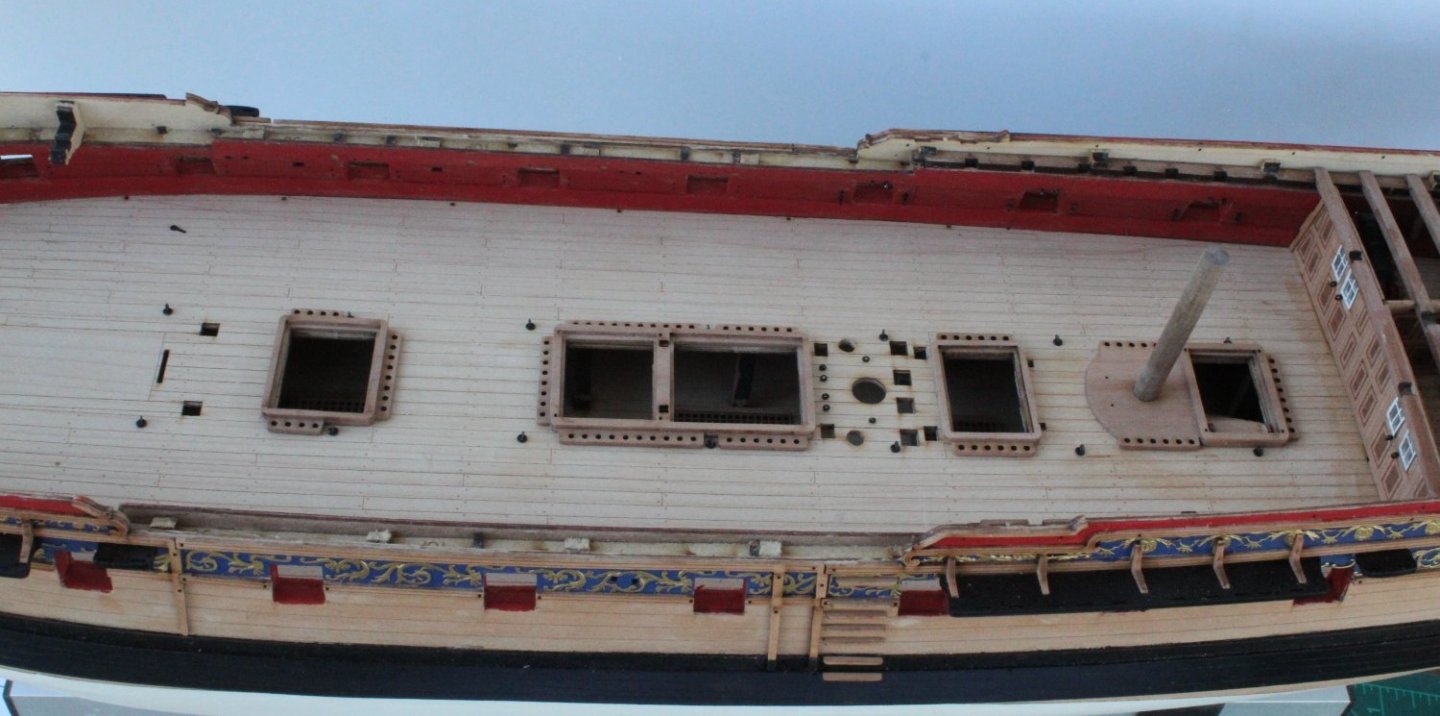
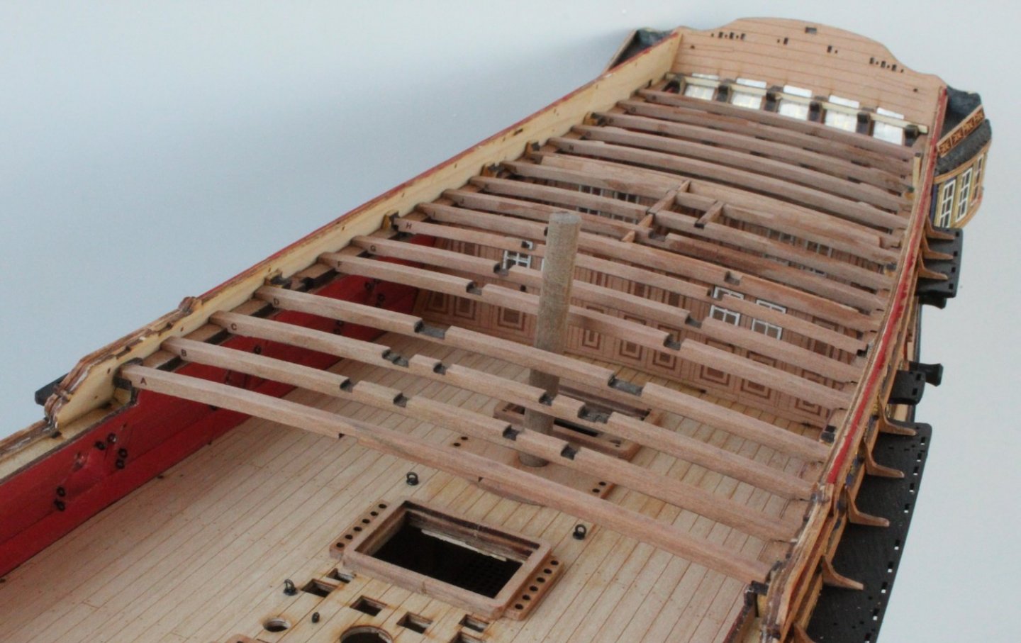
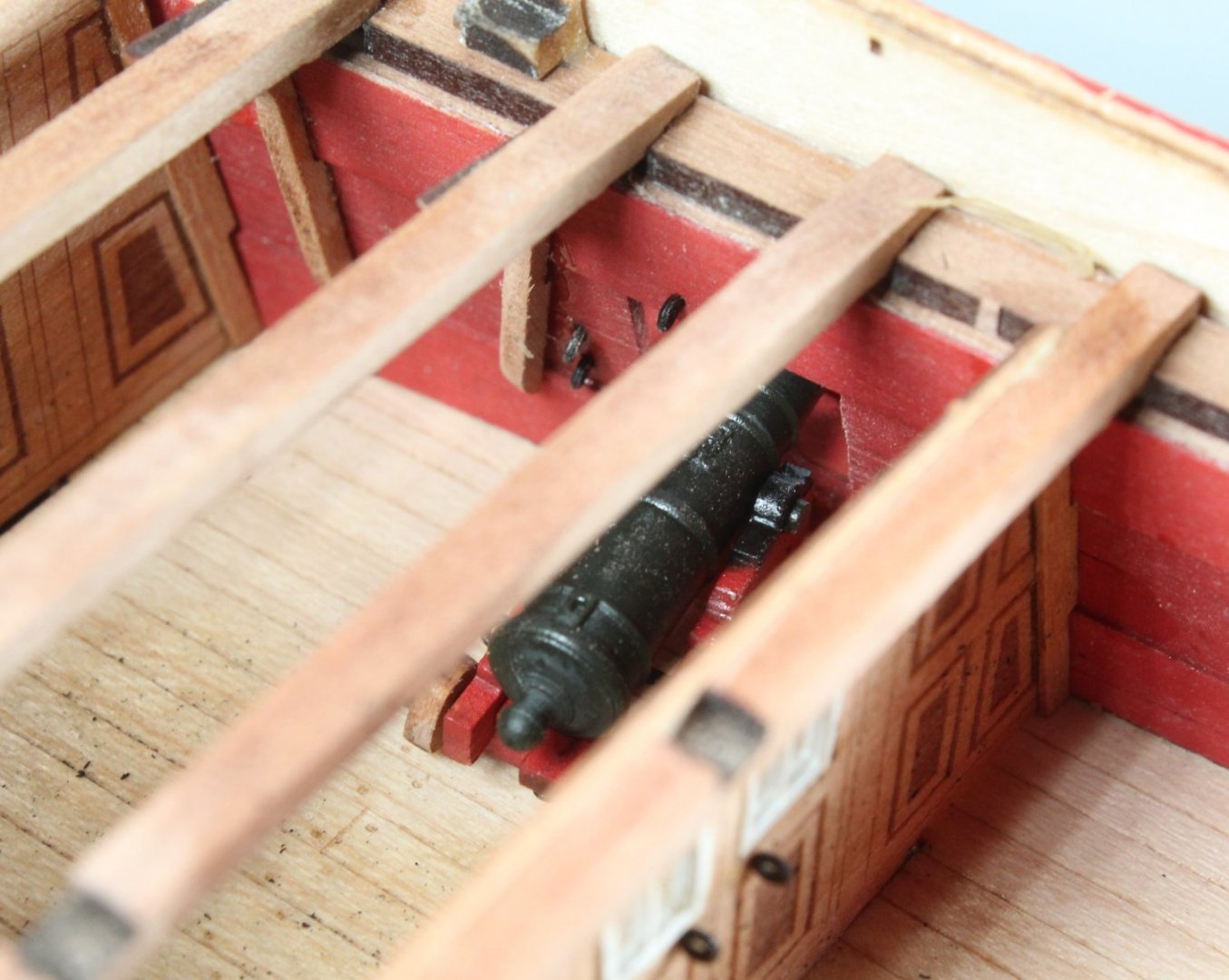
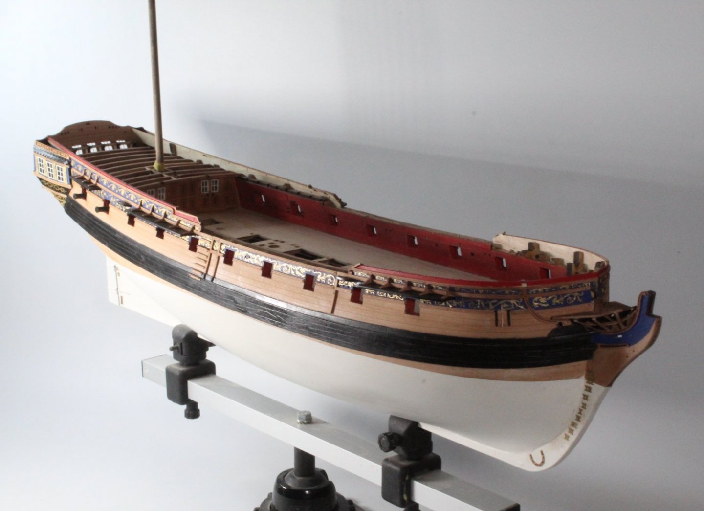
Screens Today I added the windows, frames, hinges and door handles to the forward and aft screens. I also continued to move from stern to bow with adding the quarterdeck support beams and hanging knees. I have now reached the point where I will have to move on to assembling and fitting some deck items before I can continue with adding more deck beams, starting with the gun deck aft hatch coaming, the gun deck aft ladder coaming and the gun deck aft ladder. I will also need to assembly 6 more cannons and fit all the iron work (eyebolts and rings) to the gun ports and deck. The following is a photo of the Sphinx in all her glory. Please note I have also inserted a dowel for the mizzen mast. This was to ensure the mizzen mast base was correctly positioned with the elongated hole running from stern to bow when it was glued to the deck. The yellow tape on the dowel is an indication where the mast should be aligned with the quarterdeck, when the mizzen mast is fitted and fully engaged with the bottom locating slot. The window frames are not great looking, will be OK when the quarterdeck is fitted as not easy to see. The ships captain also needs to get a rating to clean the windows The next photo show the dividing screen A cheeky picture of the cannon, the hanging knees may be painted red to match the bulwarks.


- 476 replies
-
- 7
-
-
- sphinx
- vanguard models
- (and 1 more)
-
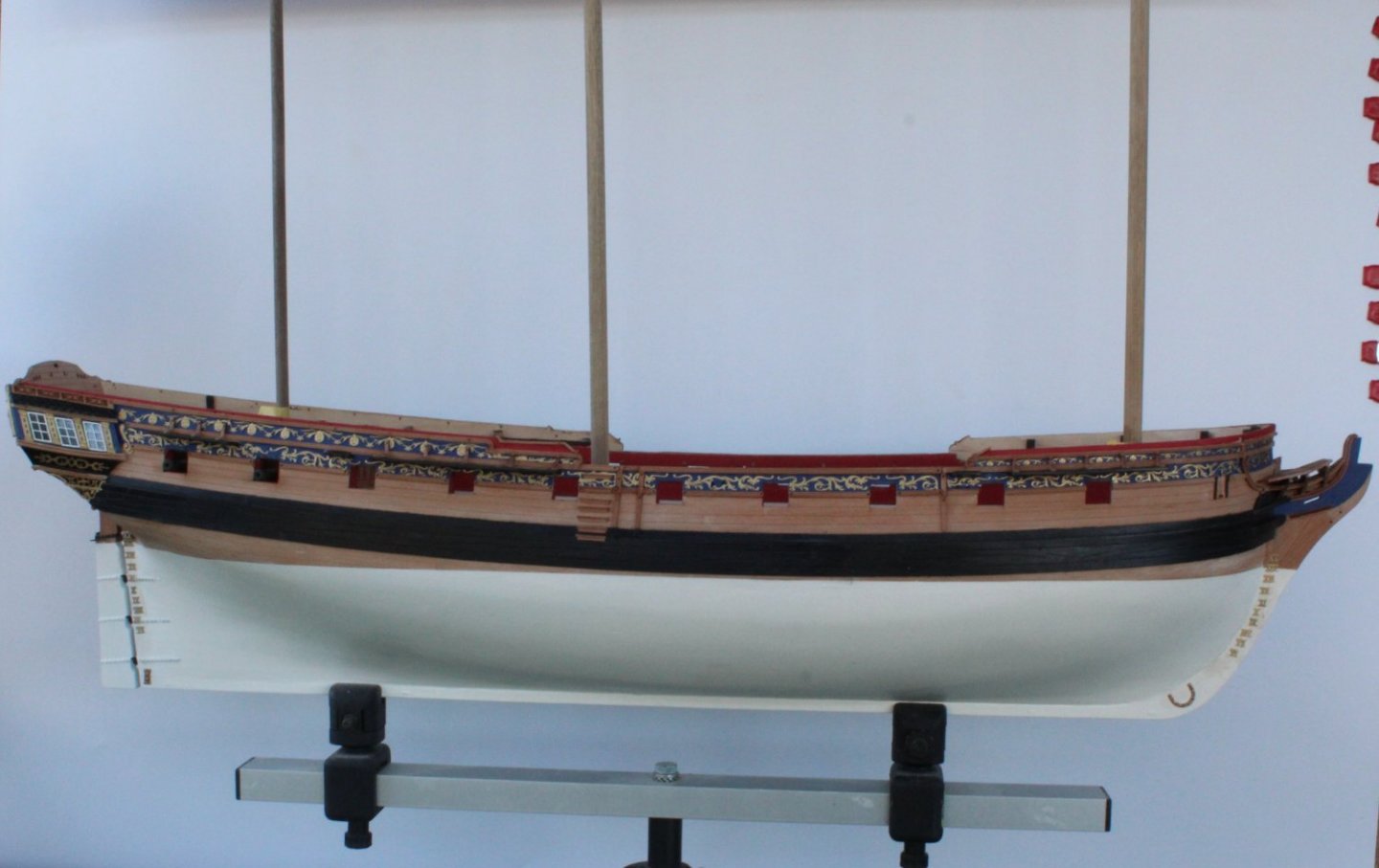
The V1 is currently on display in the conservatory along with all my other models. The conservatory is also my shipyard. I am not sure what I will do with her when the v2 build is completed
- 476 replies
-
- 2
-
-
- sphinx
- vanguard models
- (and 1 more)
-
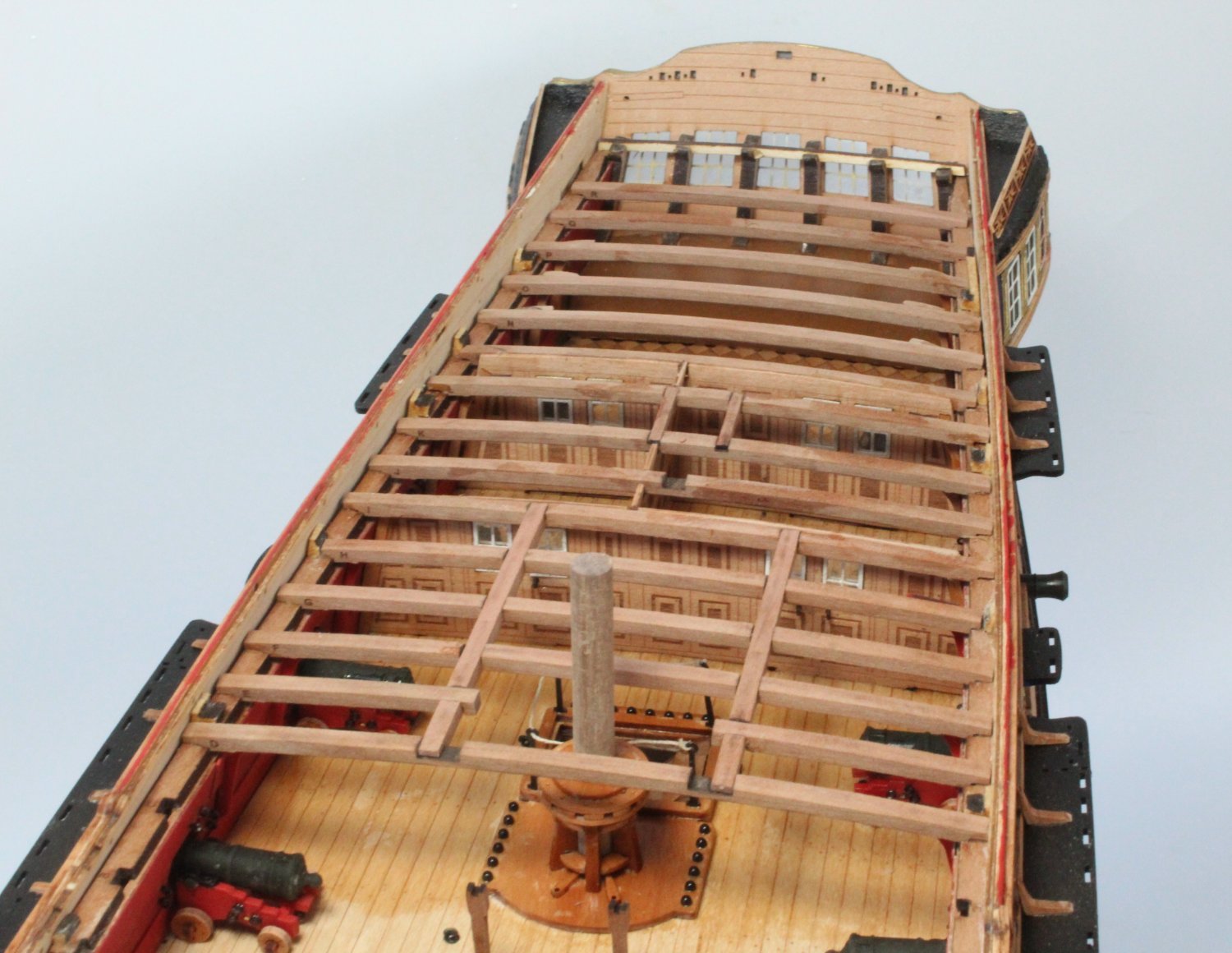
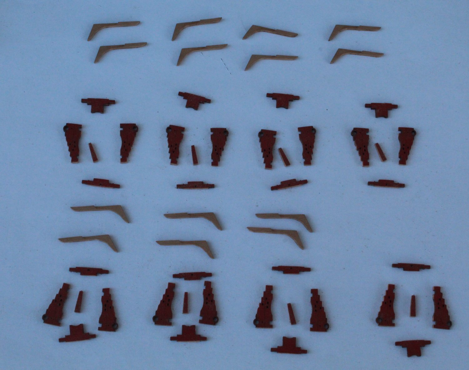
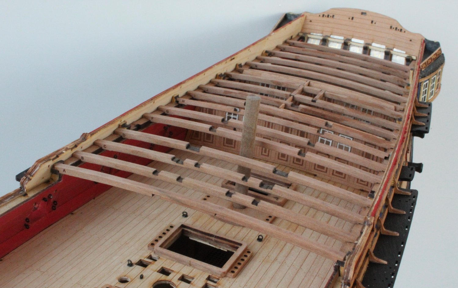
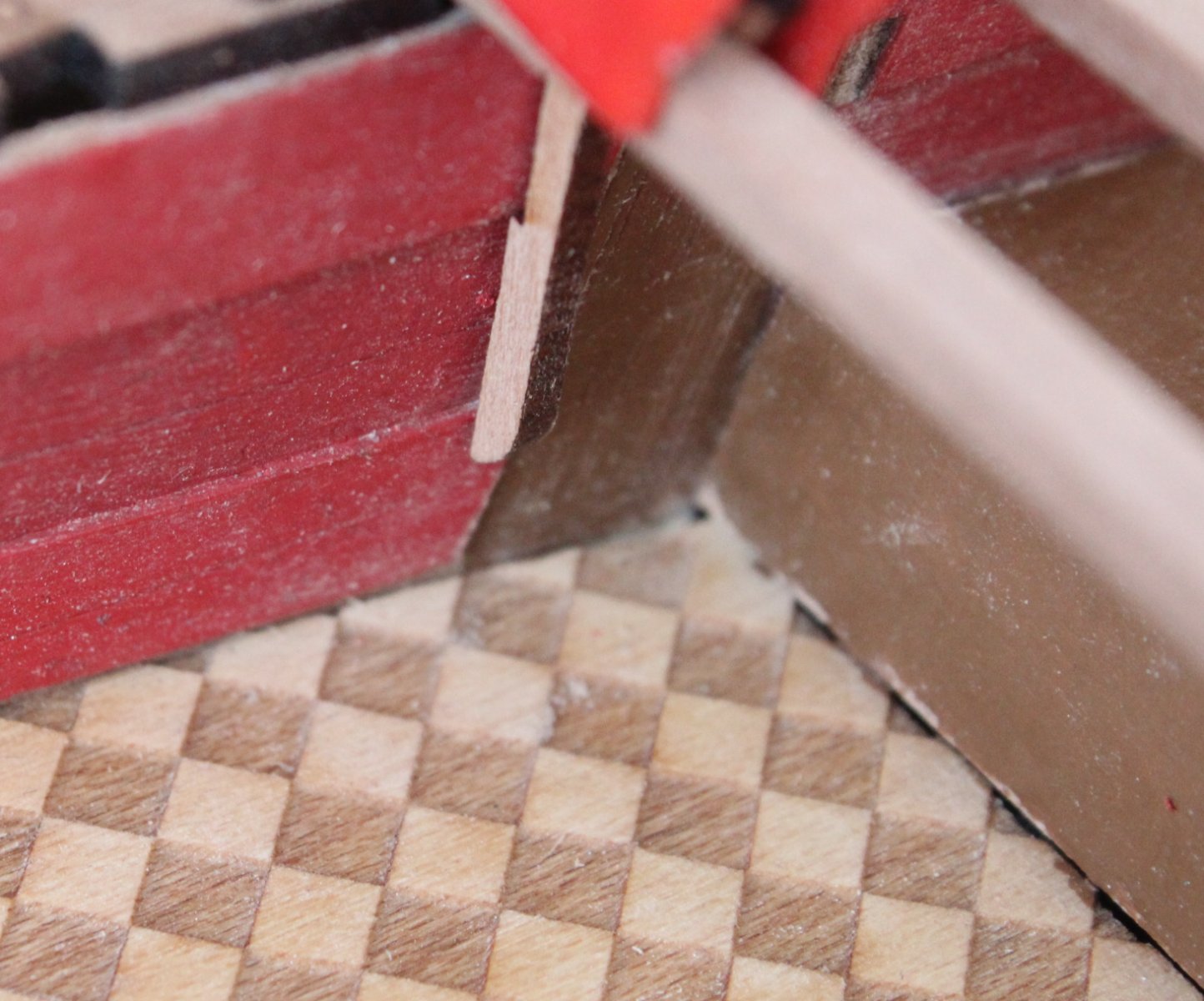
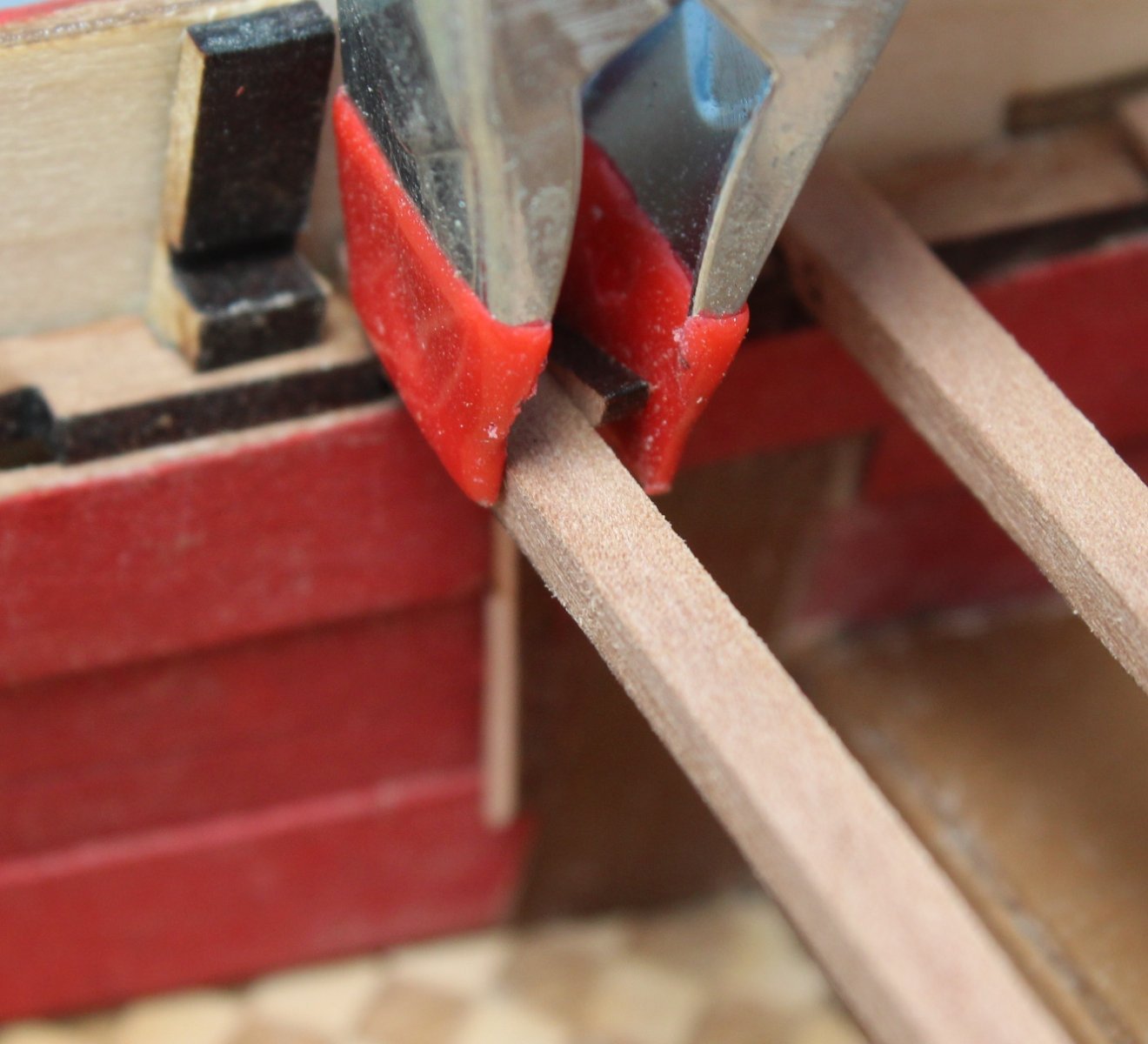
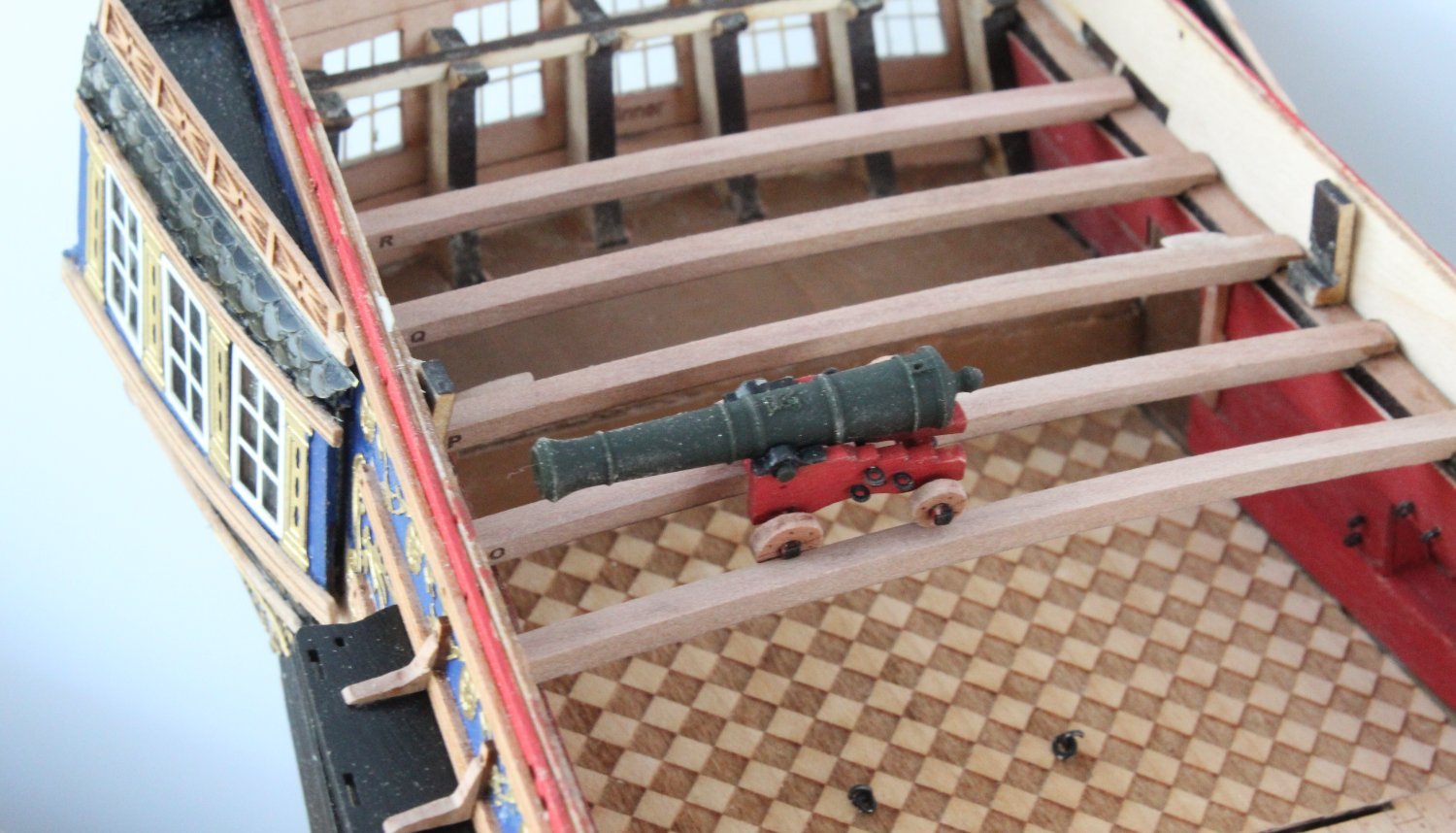
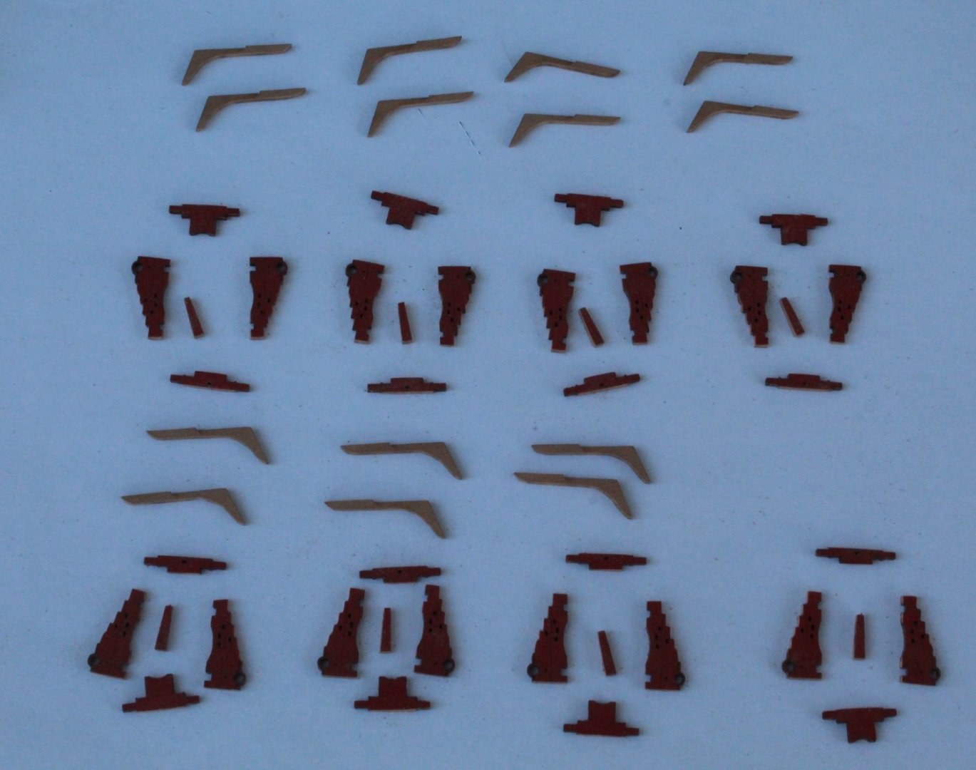
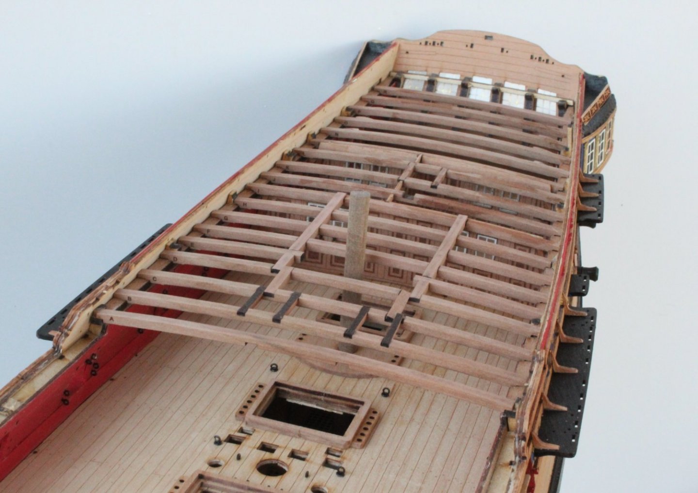
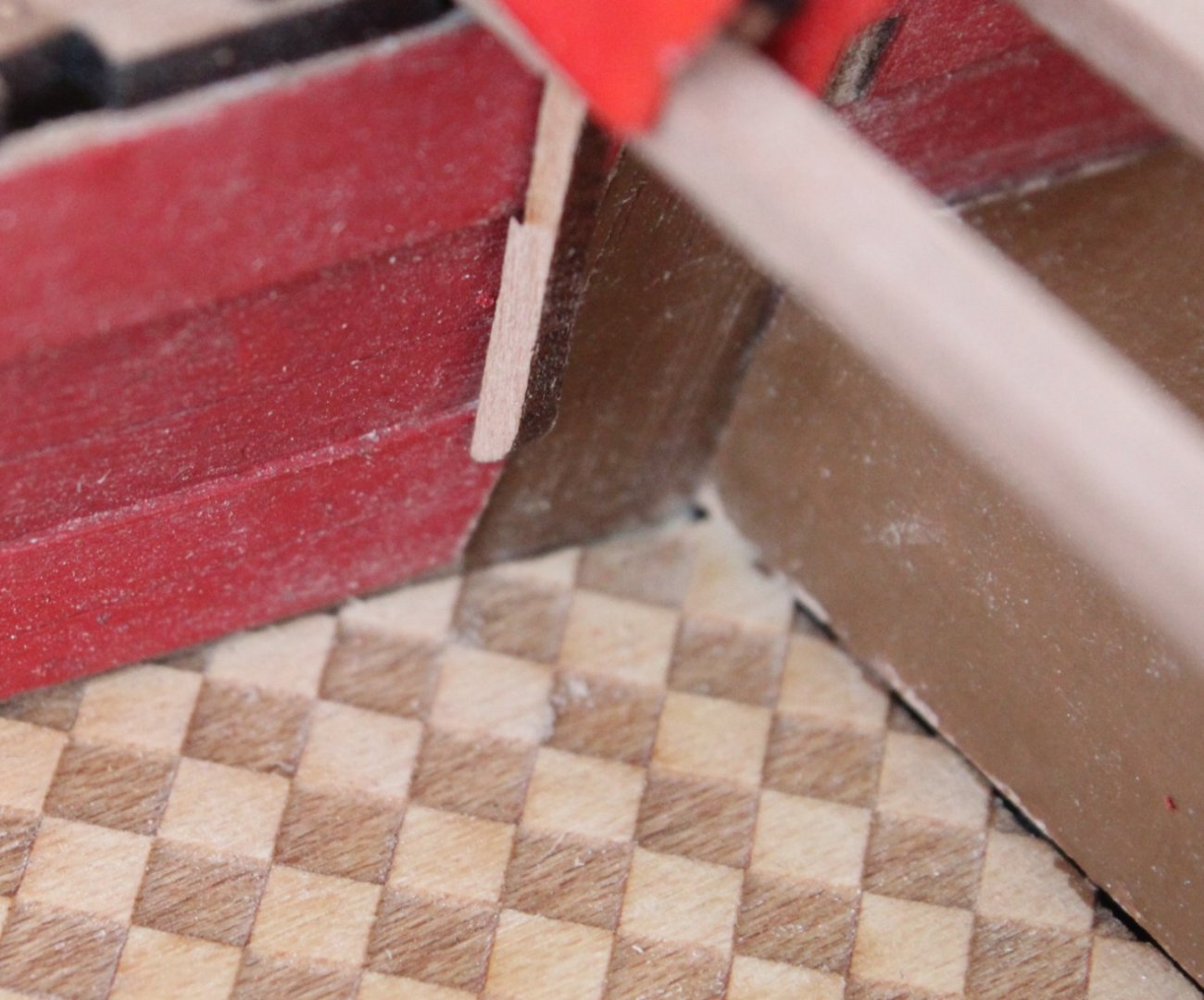
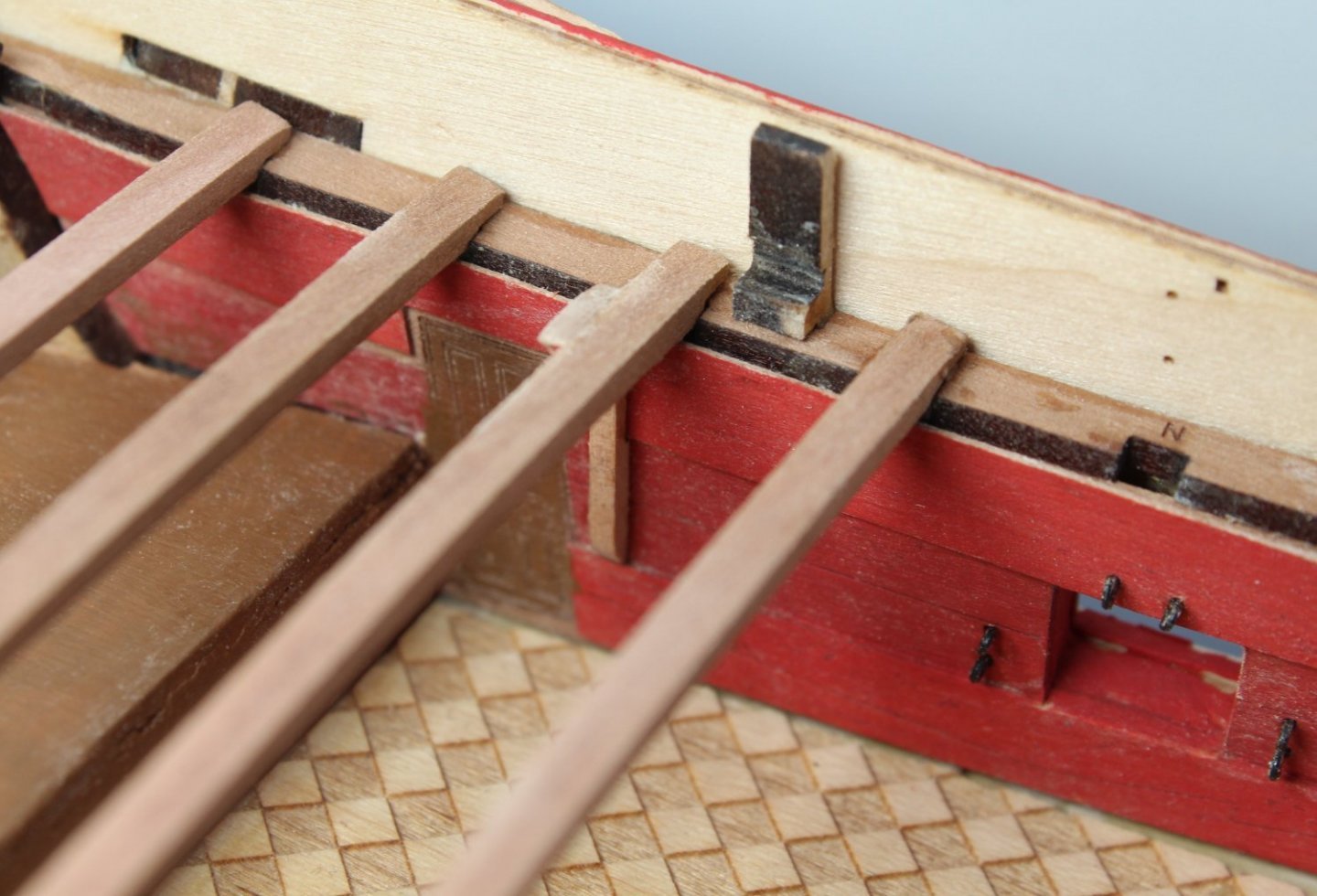
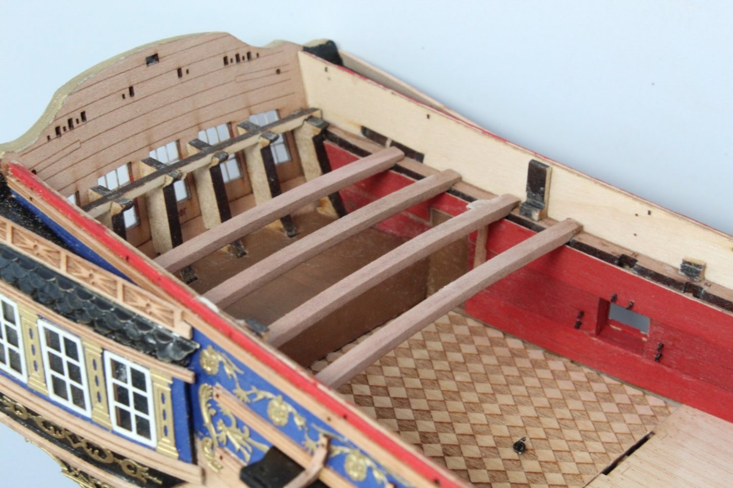
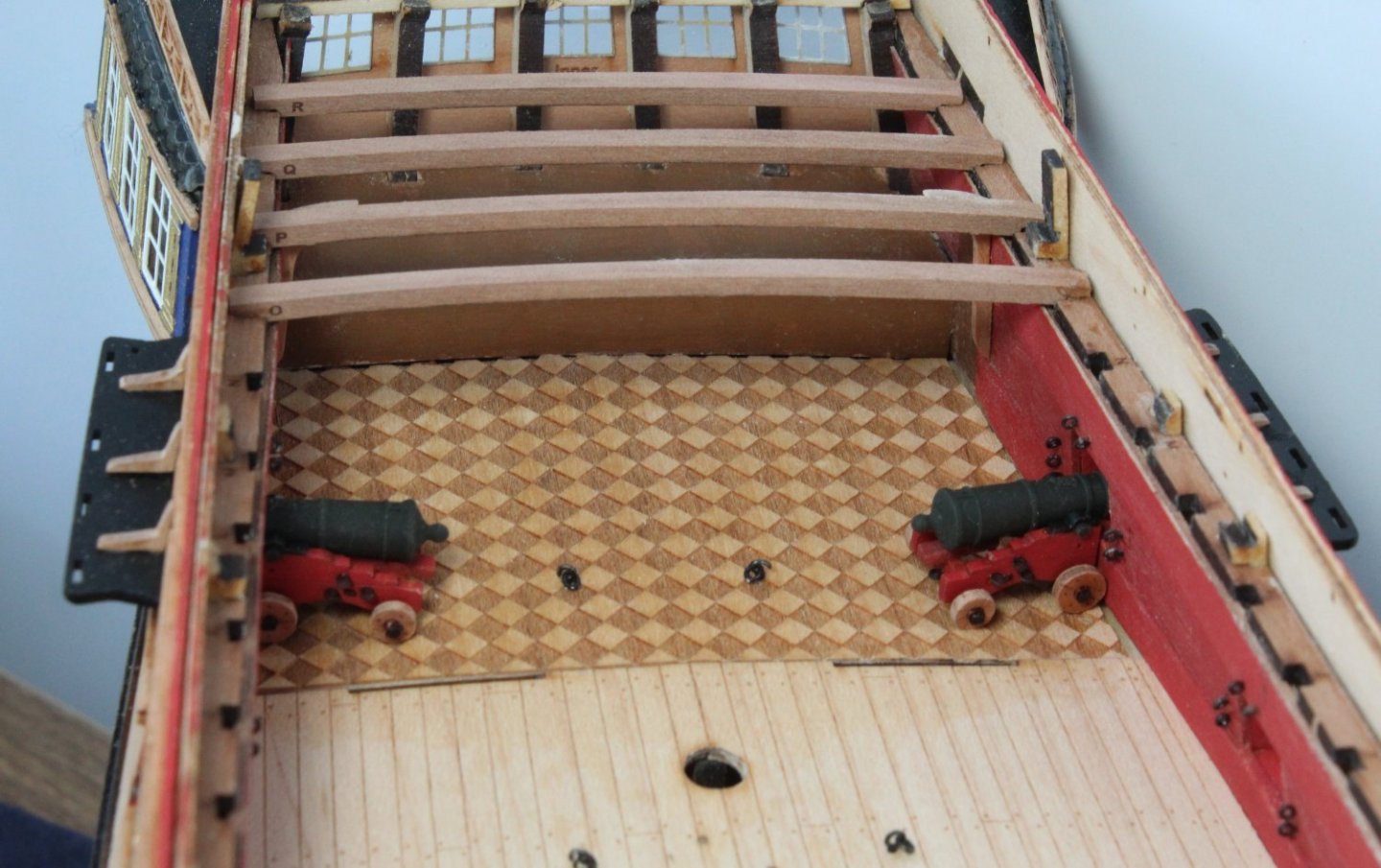
Quarterdeck Beams and optional Hanging Knees My plan for moving forward with the adding the deck items is to work steadily from stern to bow. With that in mind I have therefore started with adding the quarterdeck support beams. Before each beam is fitted the laser char is removed from the top edge. I used a medium grade Florey sanding stick initially to remove the bulk of the laser char and then I finished off the process with 320 grit sandpaper. The hanging knees will also be added at the same time, as I think there are much easier to fit along with each beam. When dry fitting the first hanging knee I noted a couple of things which needed some minor attention. As can be seen in the photo below the bottom edge of the handing knee is too long. Also the top edge of the hanging knee will require a bit of trimming to match the curve of the quarterdeck beam, as shown in the photo below. After a few minutes work the I was happy with the fit. I then removed the laser char. The hanging knee was then glued in place as can be seen in the photo below. The first four quarterdeck beams have now been installed without any problems. The 2 cannons have not been glued in place in the picture below It is important to ensure the cannons are secured in place as the quarterdeck beams are added because the cannons will not fit between the gap between the deck beams, as shown in the photo below. The leading "n" quarterdeck beam in the picture below is only dry fitted and will only be added once the cannons have been glued to the deck.


- 476 replies
-
- 8
-
-
- sphinx
- vanguard models
- (and 1 more)