Glenn-UK
-
Posts
3,166 -
Joined
-
Last visited
Content Type
Profiles
Forums
Gallery
Events
Everything posted by Glenn-UK
-
 Looks very nice, great work
 -
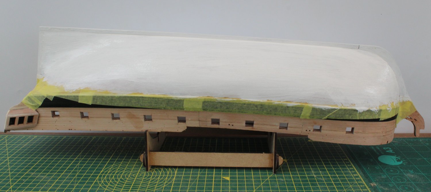
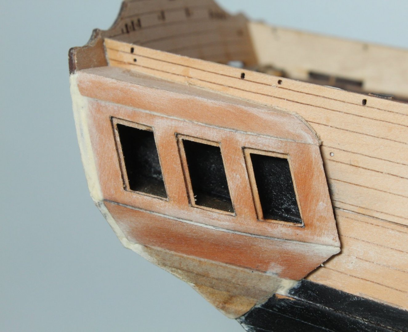
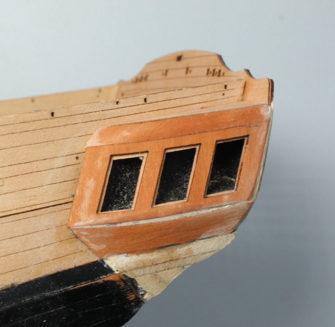
Quarter Galleries and Hull Painting The first task today was to complete the lower finishing pattern for the quarter galleries. Using a rotary tool I carefully shaped the stern end. Once I was happy with the shaping of the stern end I moved on to bevelling the front end so the top edge was flush with the berthing pattern and the lower edge was tapered to a fine edge. Once again I used my rotary tool I took my time with plenty of test fits during the shaping process to make sure it was a good fit. I also used a sanding block and sanding paper for the final shaping. The photo below shows the right-hand side. I have added the filler to the side of the window pattern/ berthing pattern. I did managed to break off the leading edge of the lower finishing pattern during the shaping process. I have started to add some filler to correct and it will look Ok with a bit more fettling and then painted black. The photo below is the left-hand side quarter gallery. Again this will look Ok when the black paint has been added. The photo below show the stern view. It does not look too bad, but I will need to add a bit of filler before the black paint is added Next I taped the hull above the waterline, and using Admiralty Matt White diluted with water I brushed on the first coat of paint. Once the paint has had time to dry I will inspect the hull and then sand and fill as necessary. I am hoping this will not require too much as I did quick a bit of work in this respect when I completed the second planking. I plan to use diluted Admiralty Matt white and once I am happy the hull is smooth. If necessary I will finish off with a spray can final coat. The photo below was taken after the first coat of diluted Admiralty Matt white paint had been brushed on the hull


- 476 replies
-
- 10
-

-
- sphinx
- vanguard models
- (and 1 more)
-
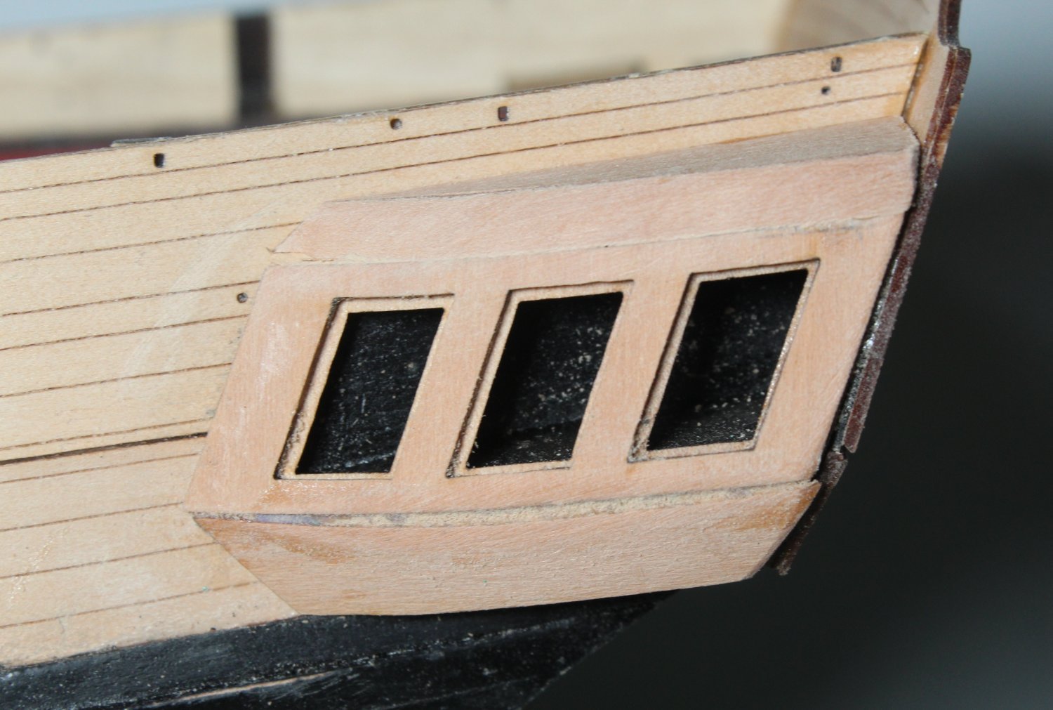
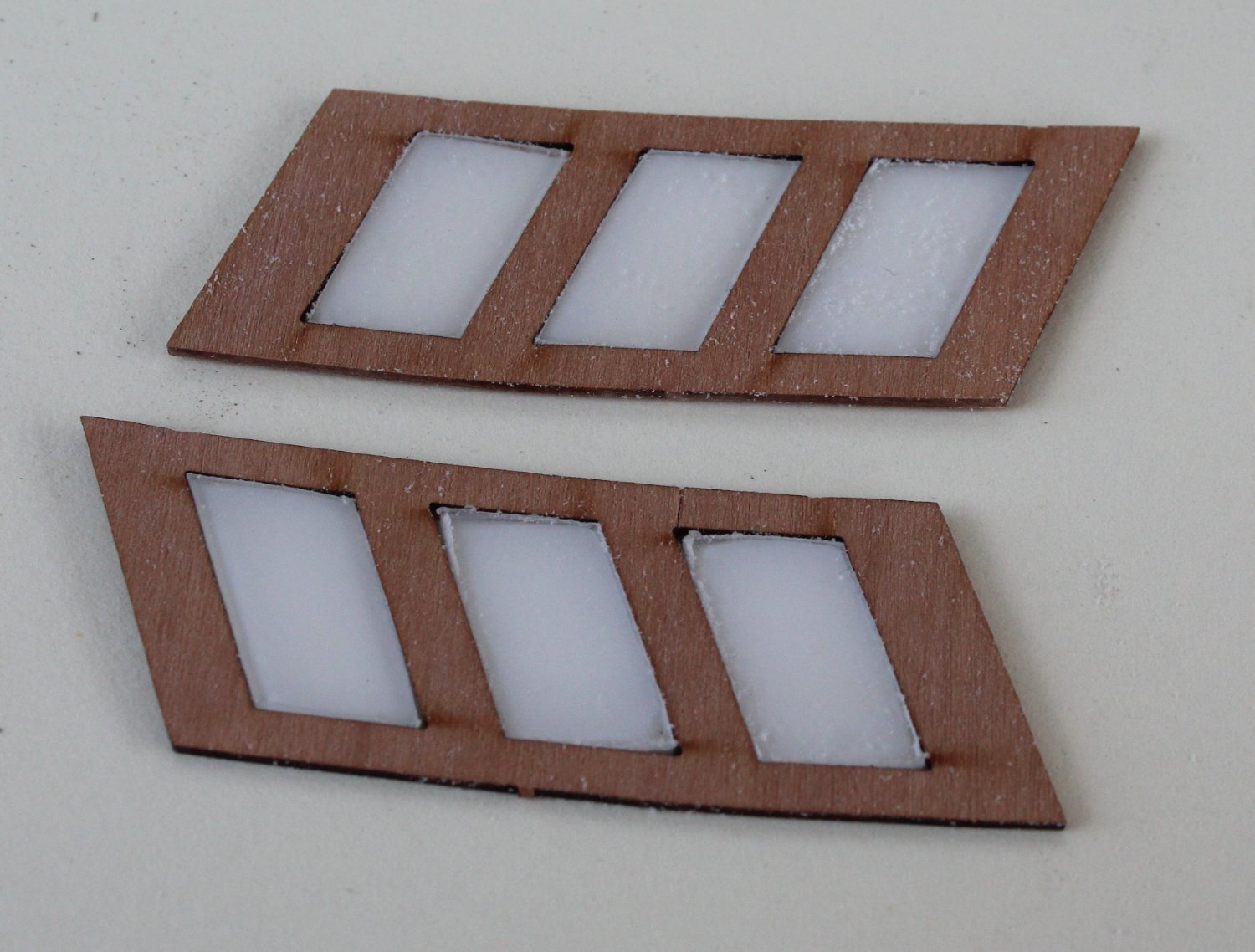
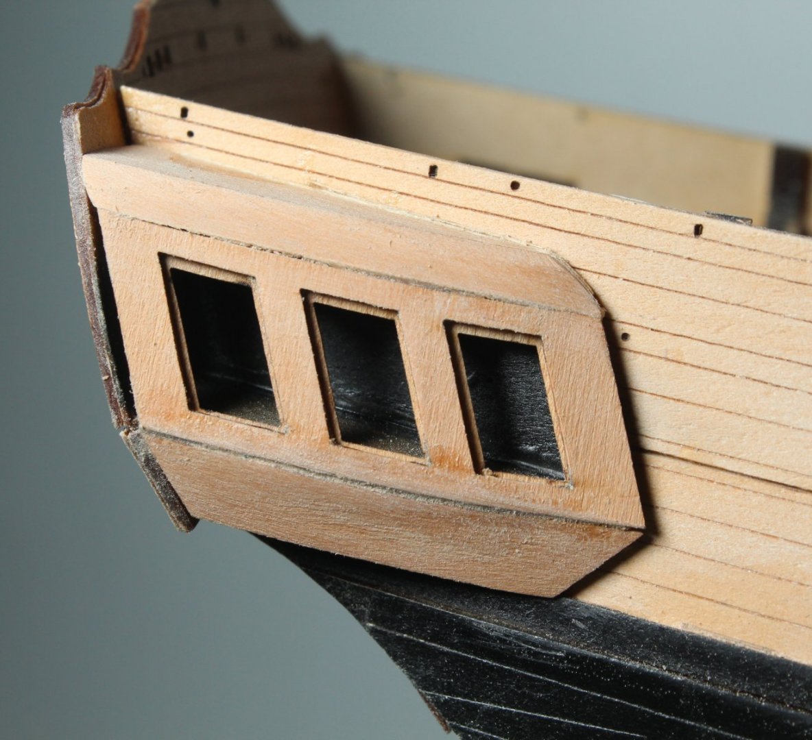
Work on Quarter Galleries Continues As with stern fascia pattern I decided to trial fit the windows to the quarter gallery window frame. They all required a bit of fettling to make them fit. Next I bevelled the front edge of the upper patterns. I also assembled the lower finishing patterns. Next I did a dry fit of the window pattern to make sure. As everything looked good. I spent a bit more time shaping the upper patterns. Once I was happy it was time to glue the various parts in place. The right-hand side looks reasonable Ok. As can be seen in the photo below I will need to fill the edge between the stern fascia and window pattern This is the left-hand side which will also require a little bit of filler. I also need to blow and brush the dust away.


- 476 replies
-
- 8
-
-
- sphinx
- vanguard models
- (and 1 more)
-
Many thanks Malcolm, overall I am very happy with this build.
- 476 replies
-
- 1
-
-
- sphinx
- vanguard models
- (and 1 more)
-
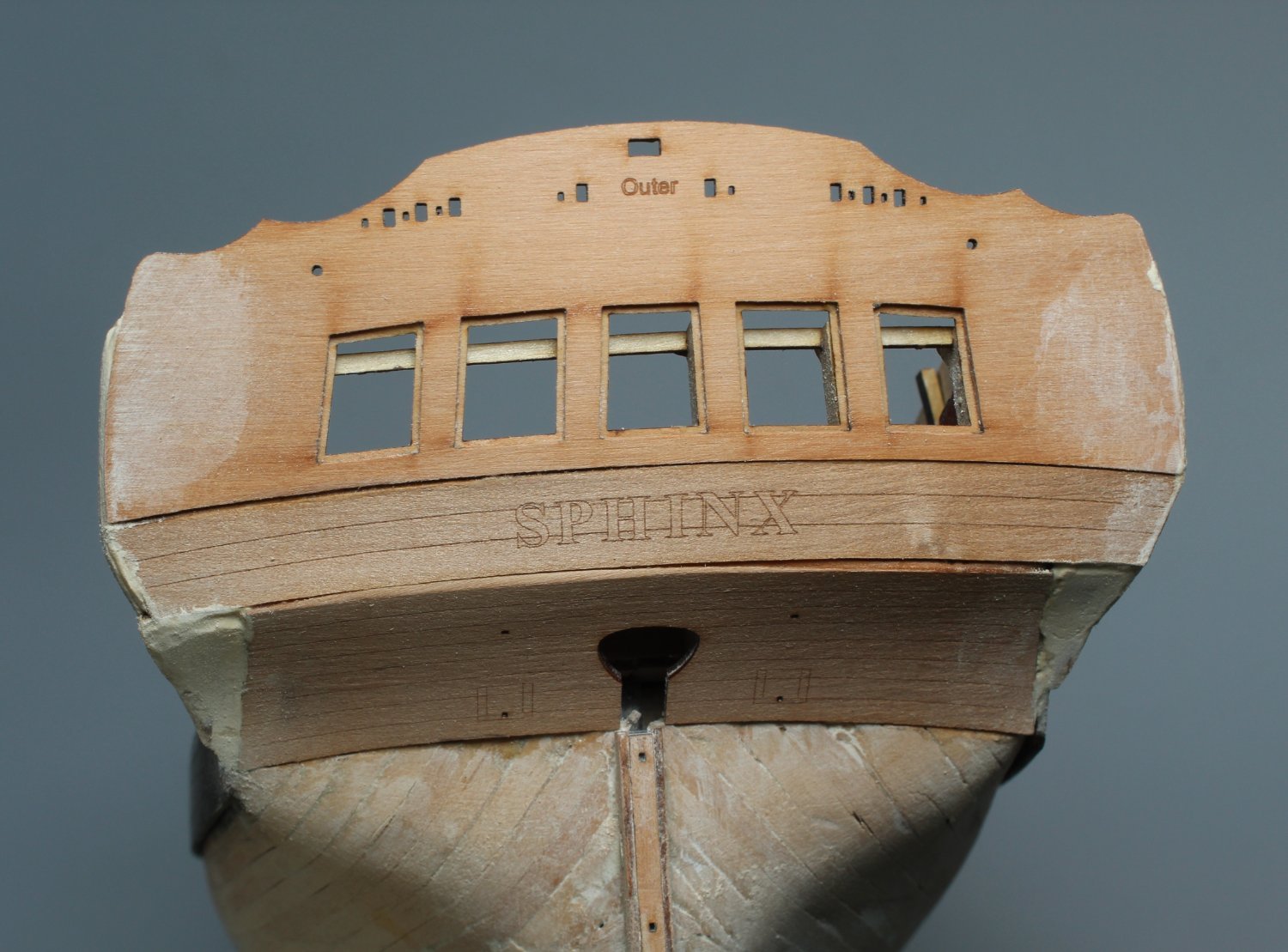
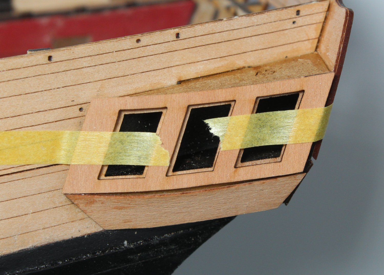
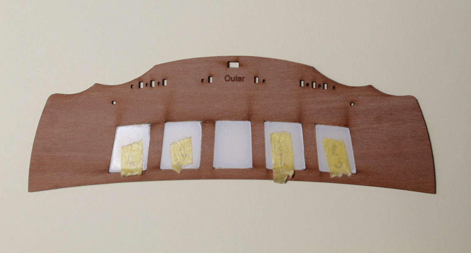
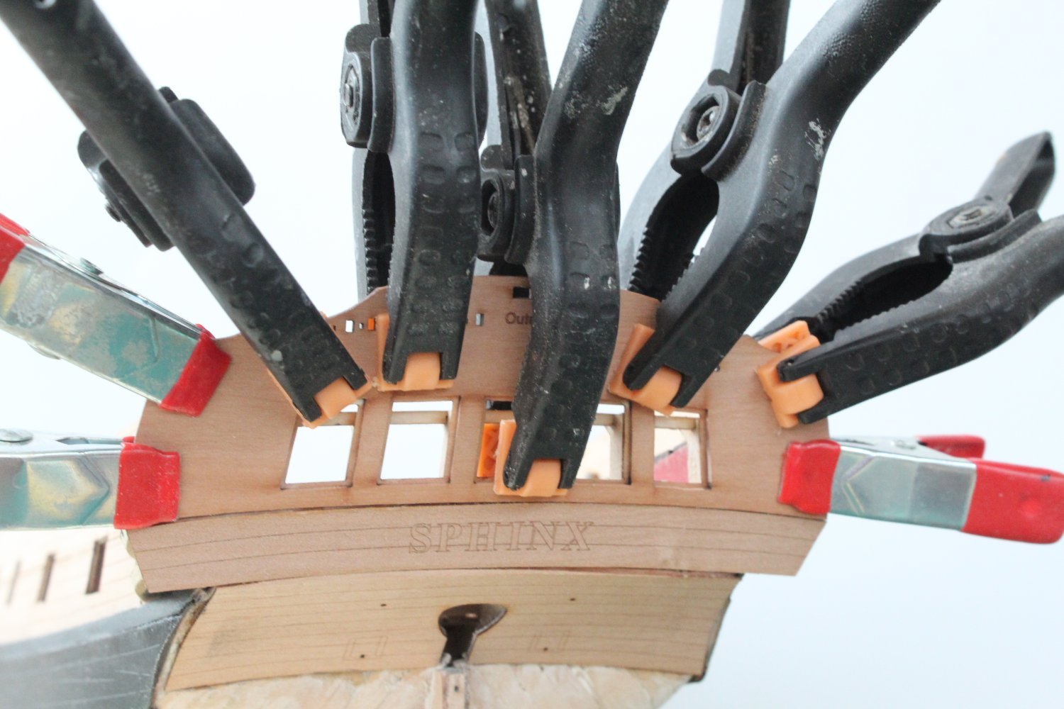
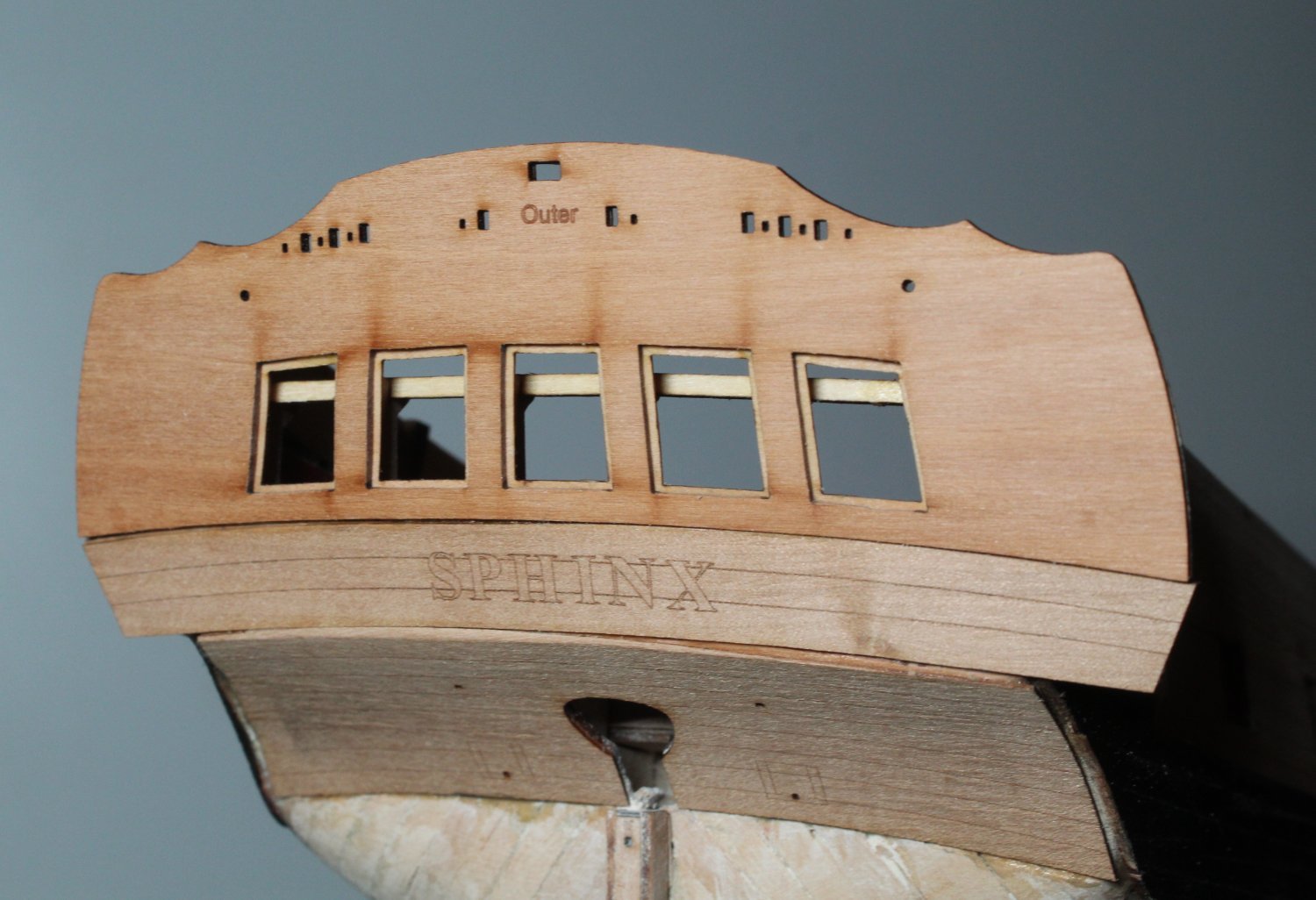
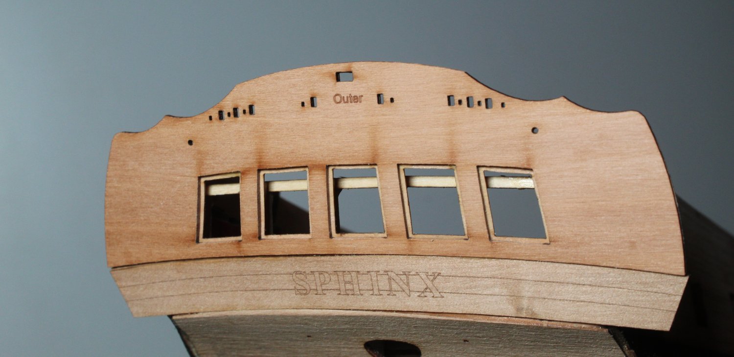
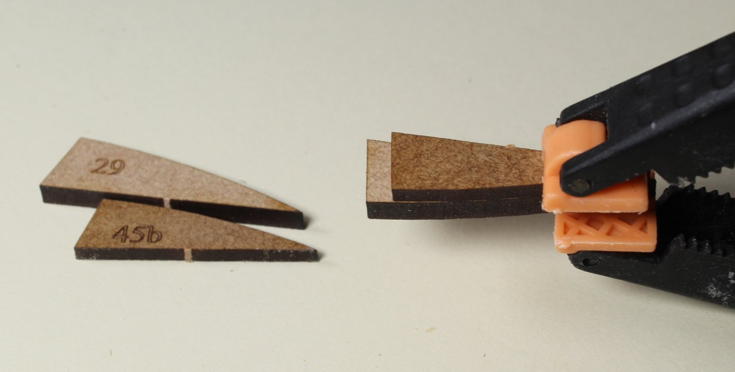
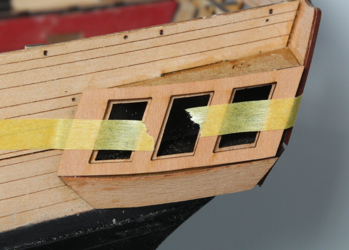
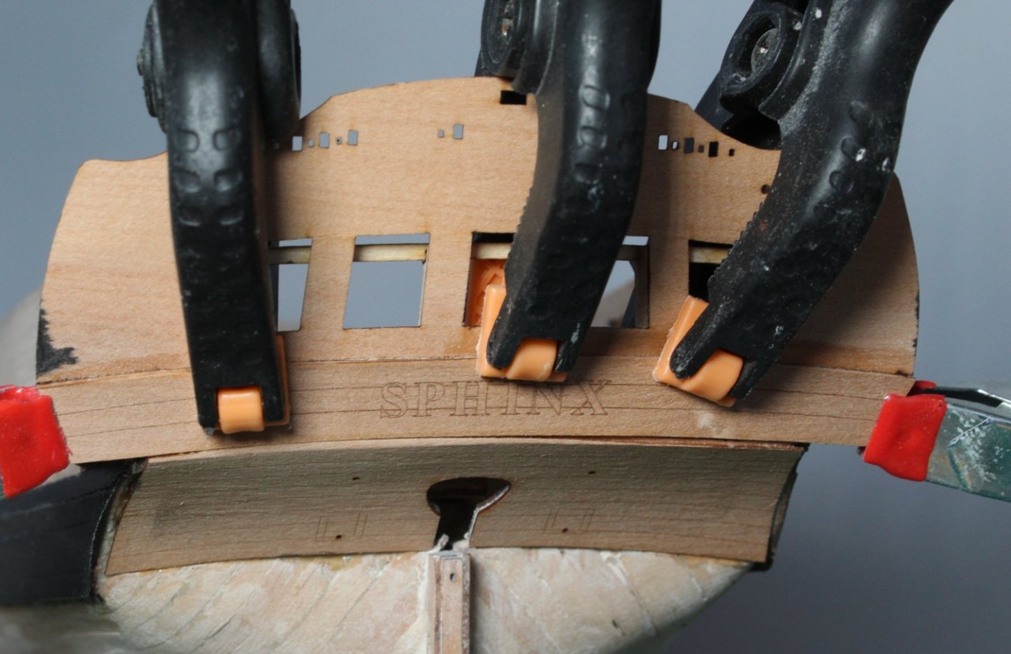
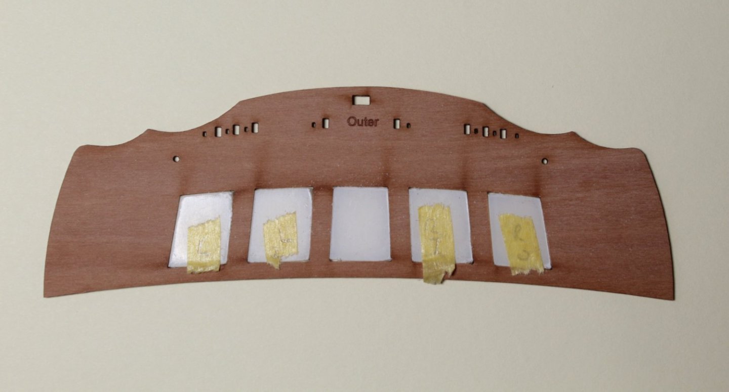
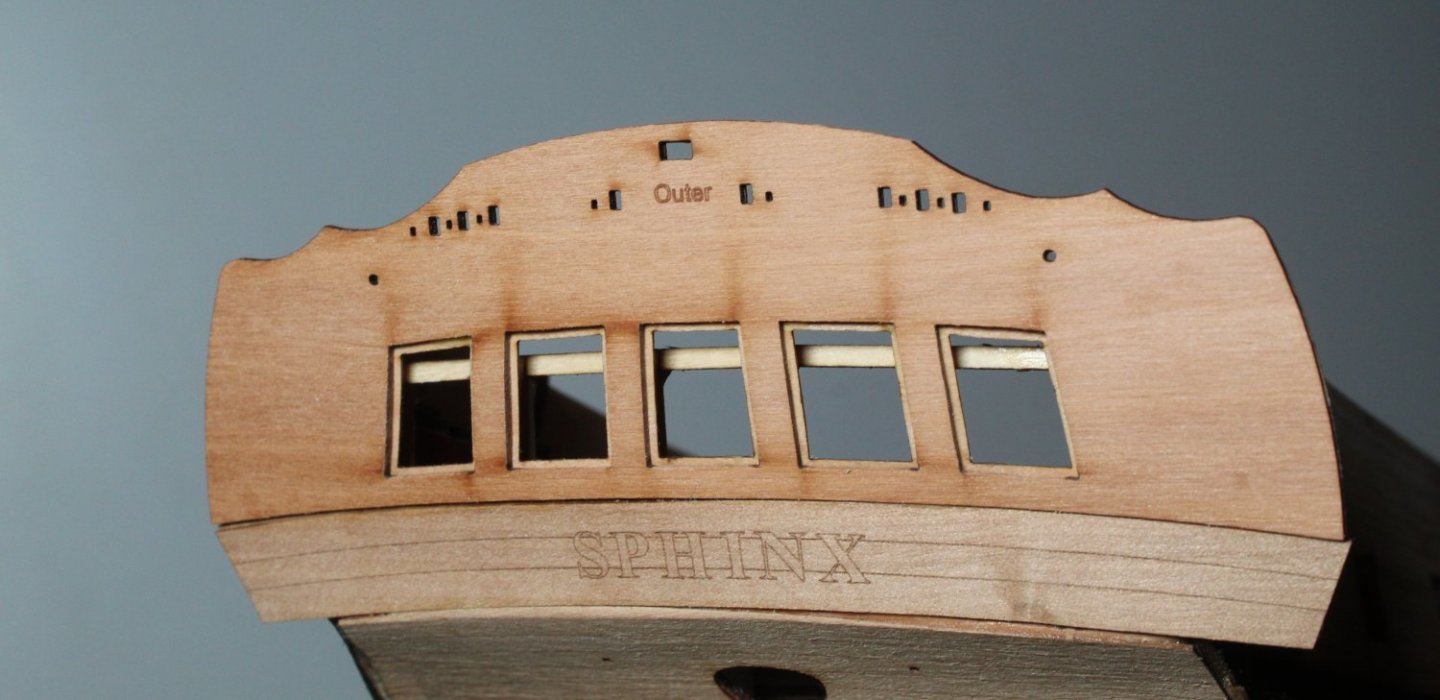
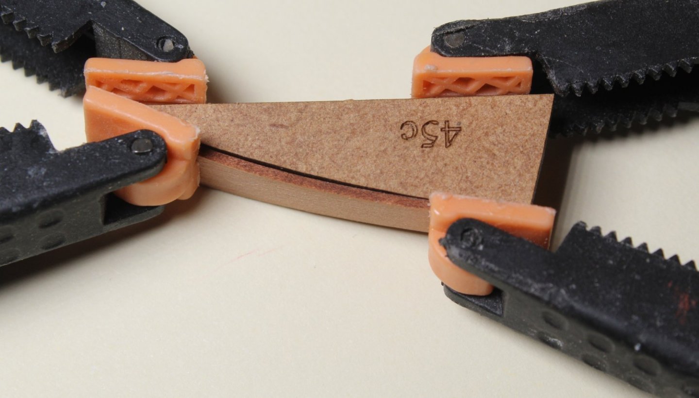
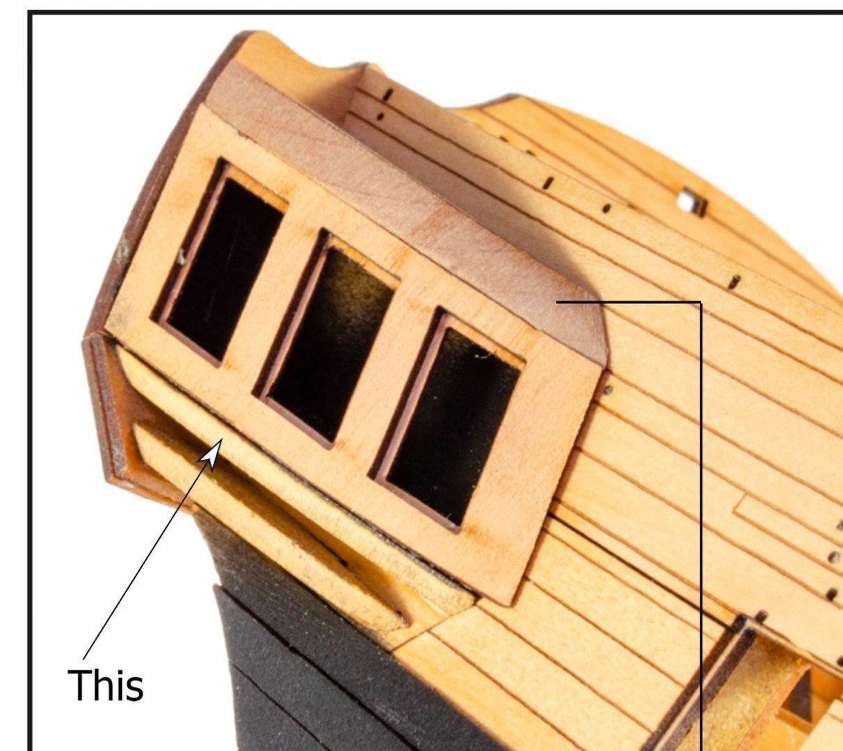
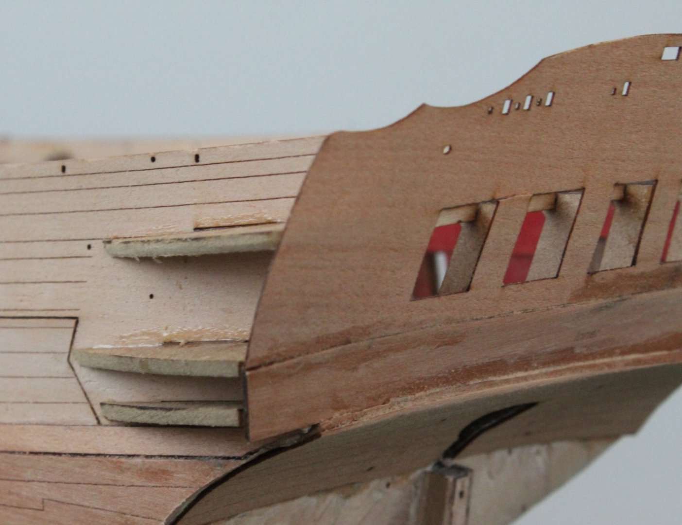
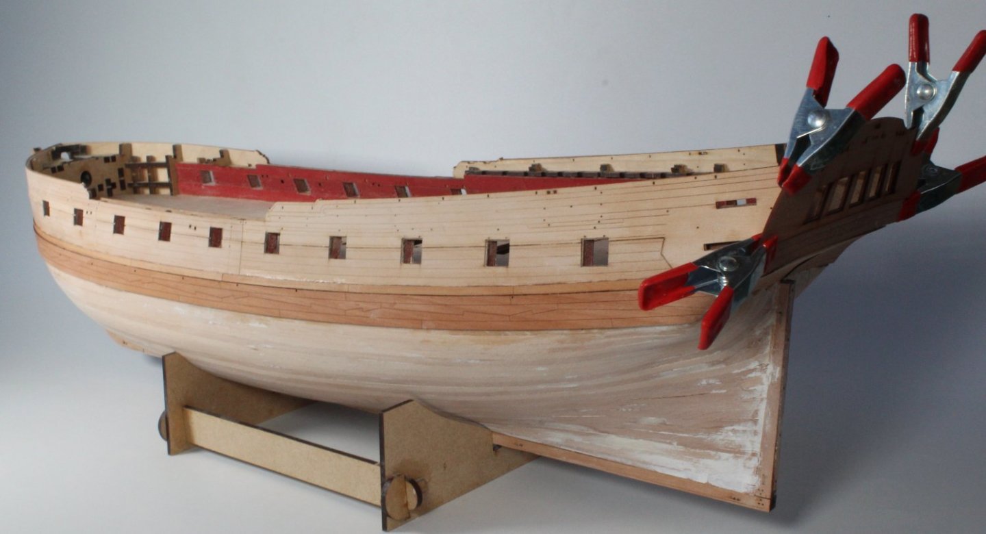
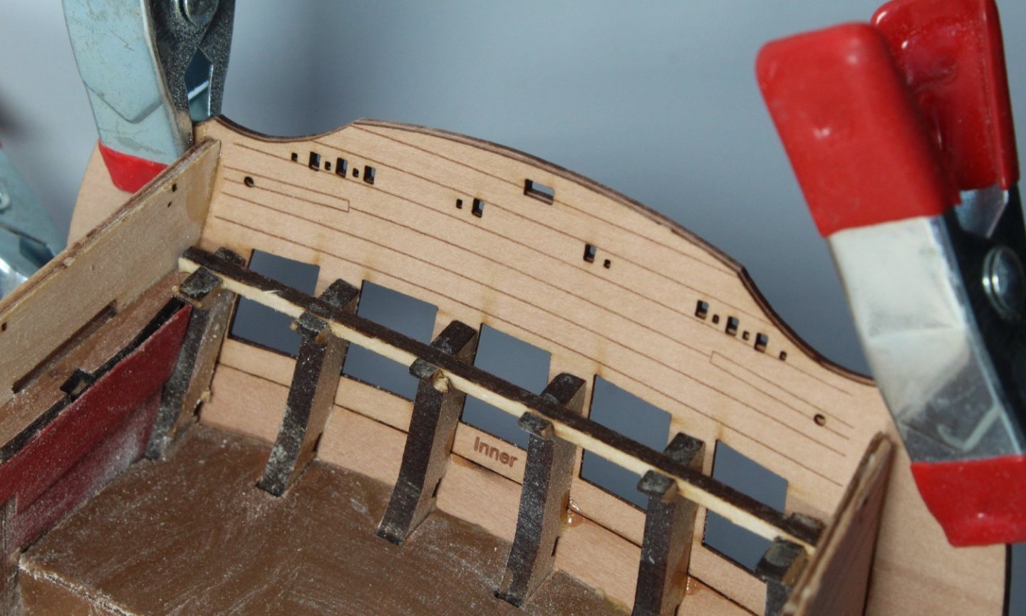
Stern and Starting Work on Quarter Galleries When looking at gluing part 29 to part 45b I was not 100% sure about how these two parts should be aligned. I think the alignment should be as shown in the photo below. Does this look correct? When I built my V1 build I was confused with build step 220 with regard to the position of part 45c. Thankfully @James H was able to send me a modified picture, which I have added to this post. It should be located directly underneath the middle gallery pattern (part 45) and not as shown in the manual which is on top of the upper gallery pattern (part 45). Moving on with todays progress the outer upper counter pattern was glued in place without any problems. While I let the glue cure I decided to test fit the windows to the outer stern fascia pattern. I recalled on the V1 build the windows did require a little bit of fettling so thought it would be easier to sort out the fitting before any of the parts were installed. I have added some tape to the windows for identification purposes to ensure the correct windows will be fitted to the right frame. The outer stern fascia pattern was then glued in place. I took plenty of time to ensure the part was properly aligned with the inner stern fascia pattern. The quarter gallery berthing pattern needs to follow the curve of the quarter gallery patterns. To make the fitting process a bit easier I applied a bit of moisture to the berthing patterns and then clamped them to part 45c. These will be left overnight to fully dry out and hopefully they will have retained the required bend.


- 476 replies
-
- 11
-
-
- sphinx
- vanguard models
- (and 1 more)
-
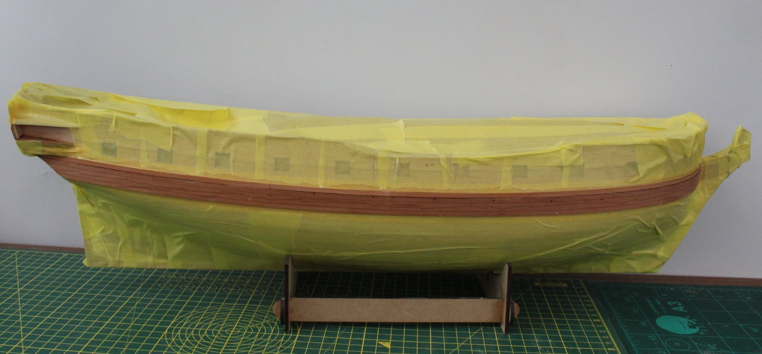
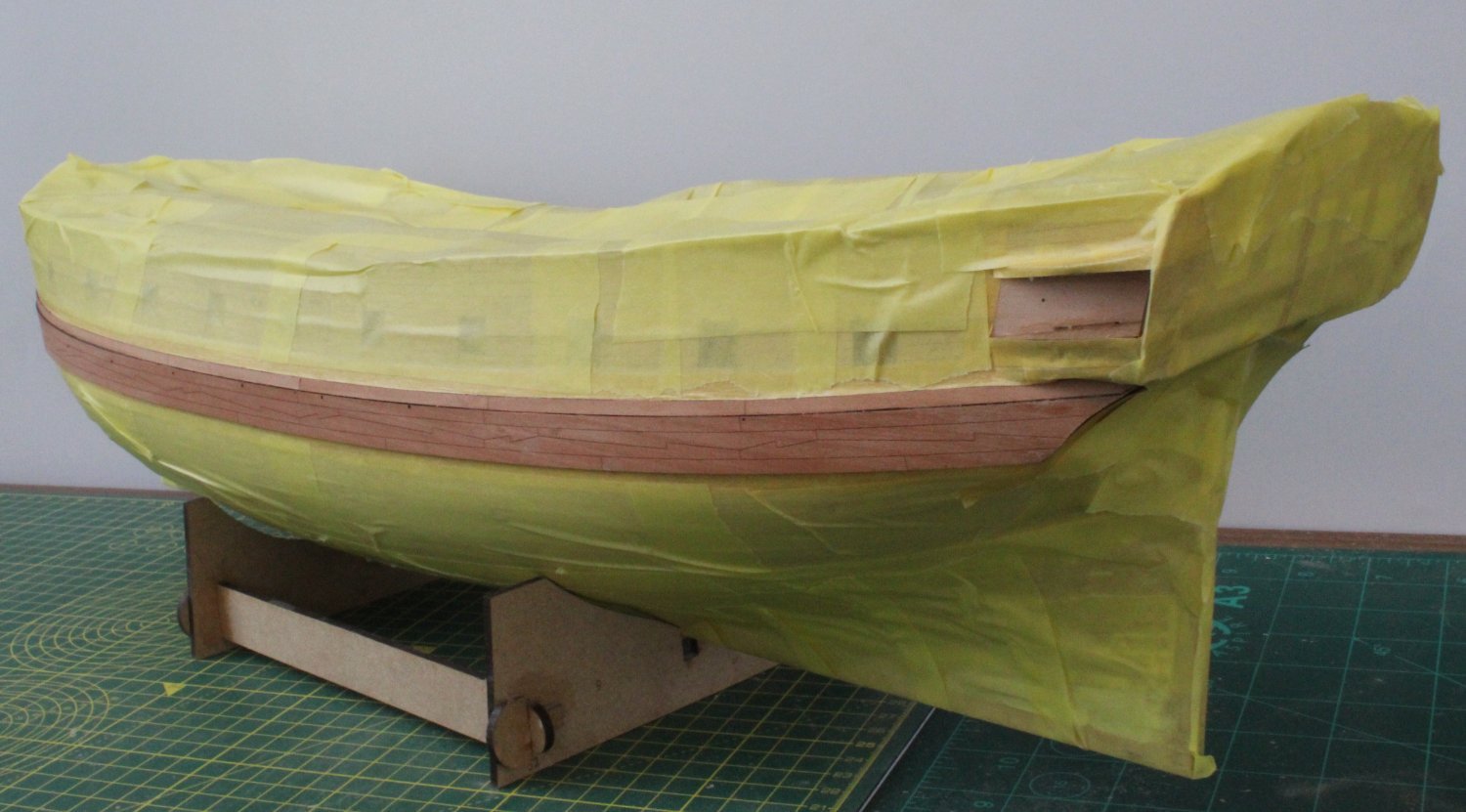
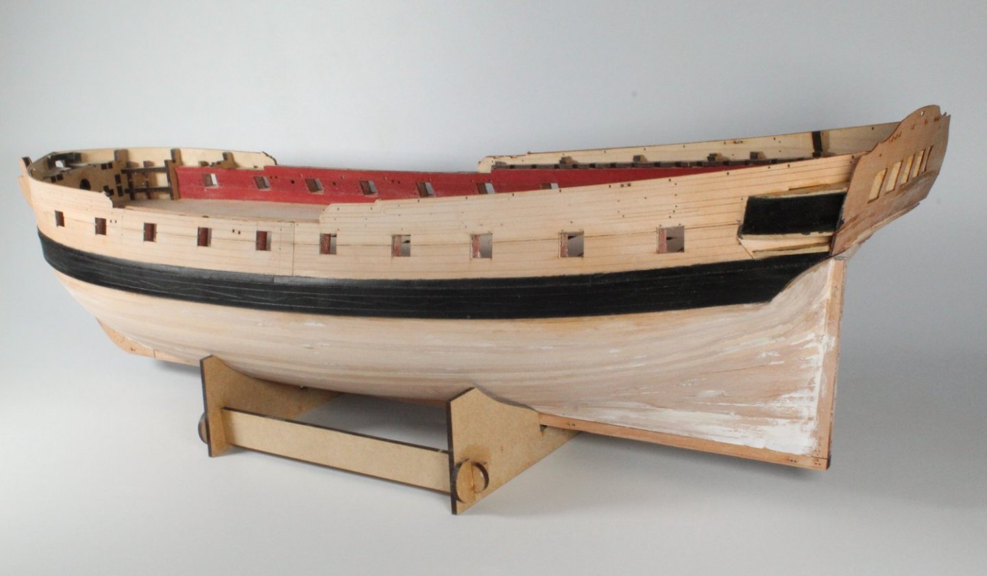
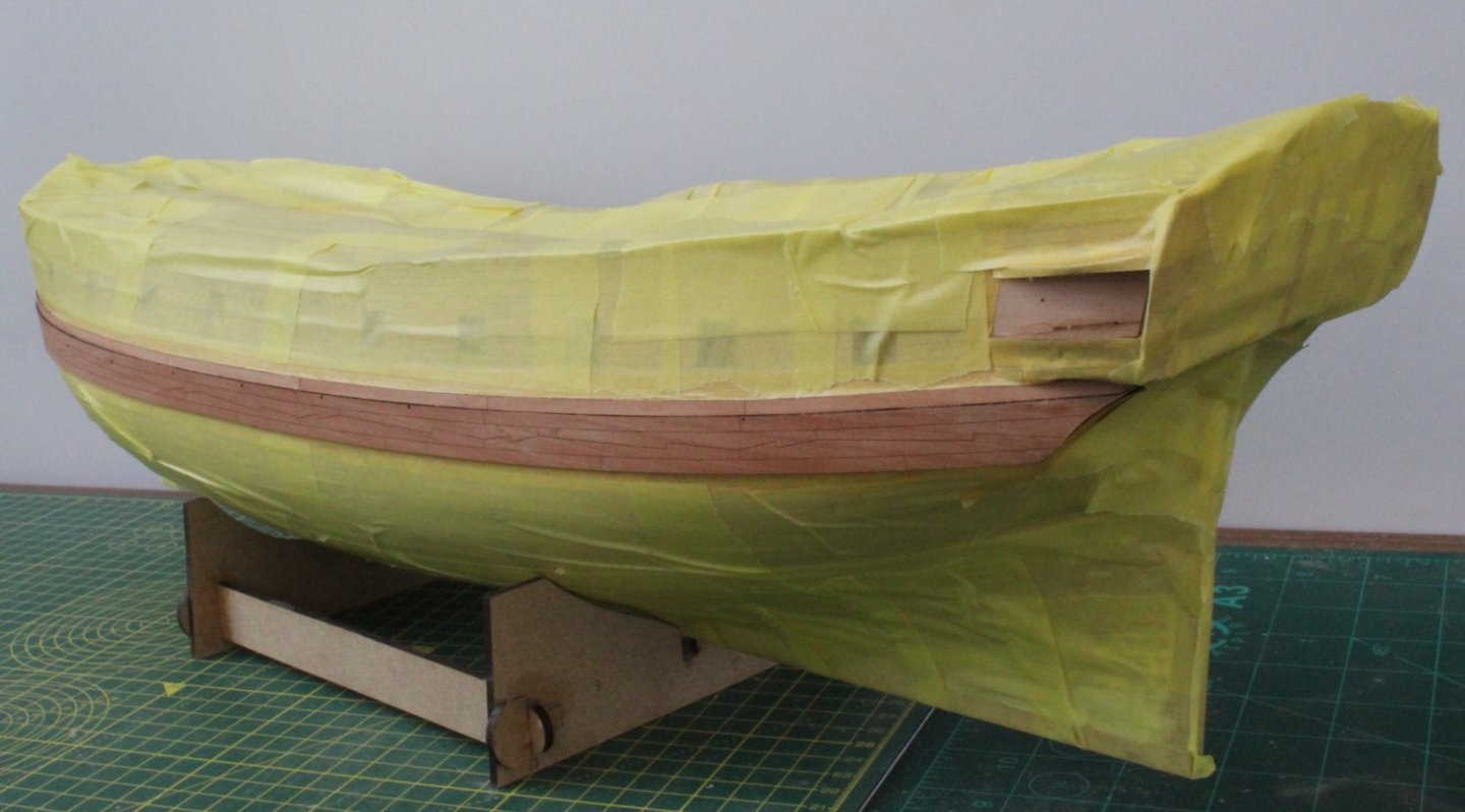
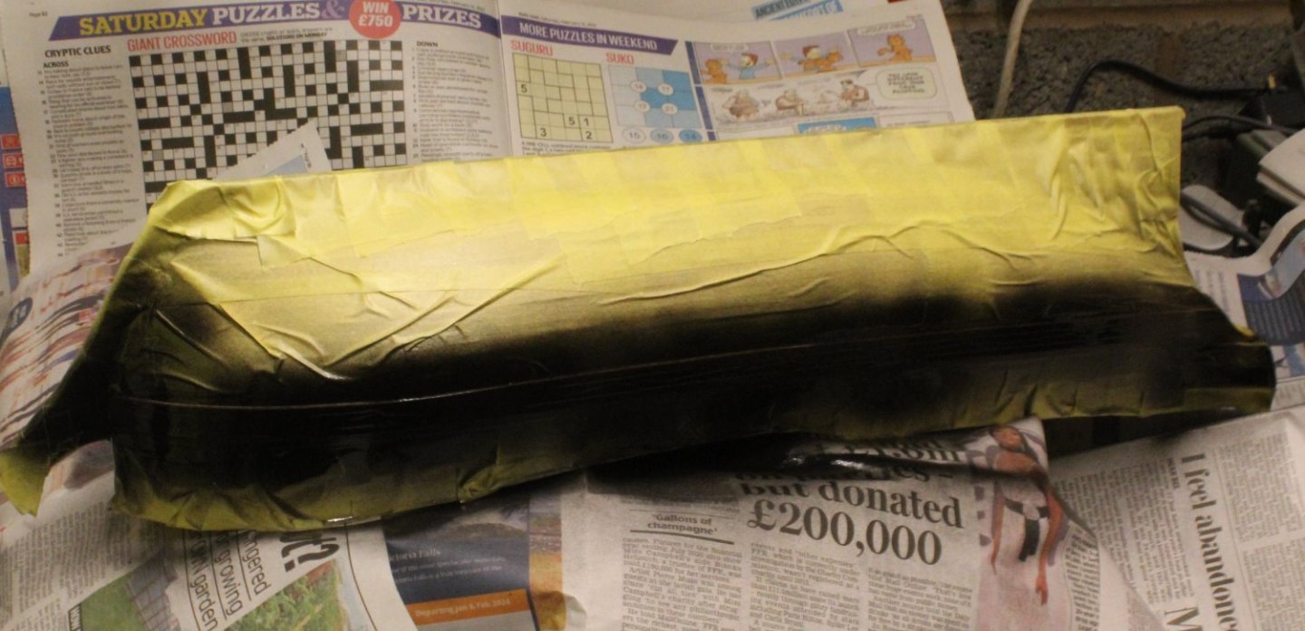
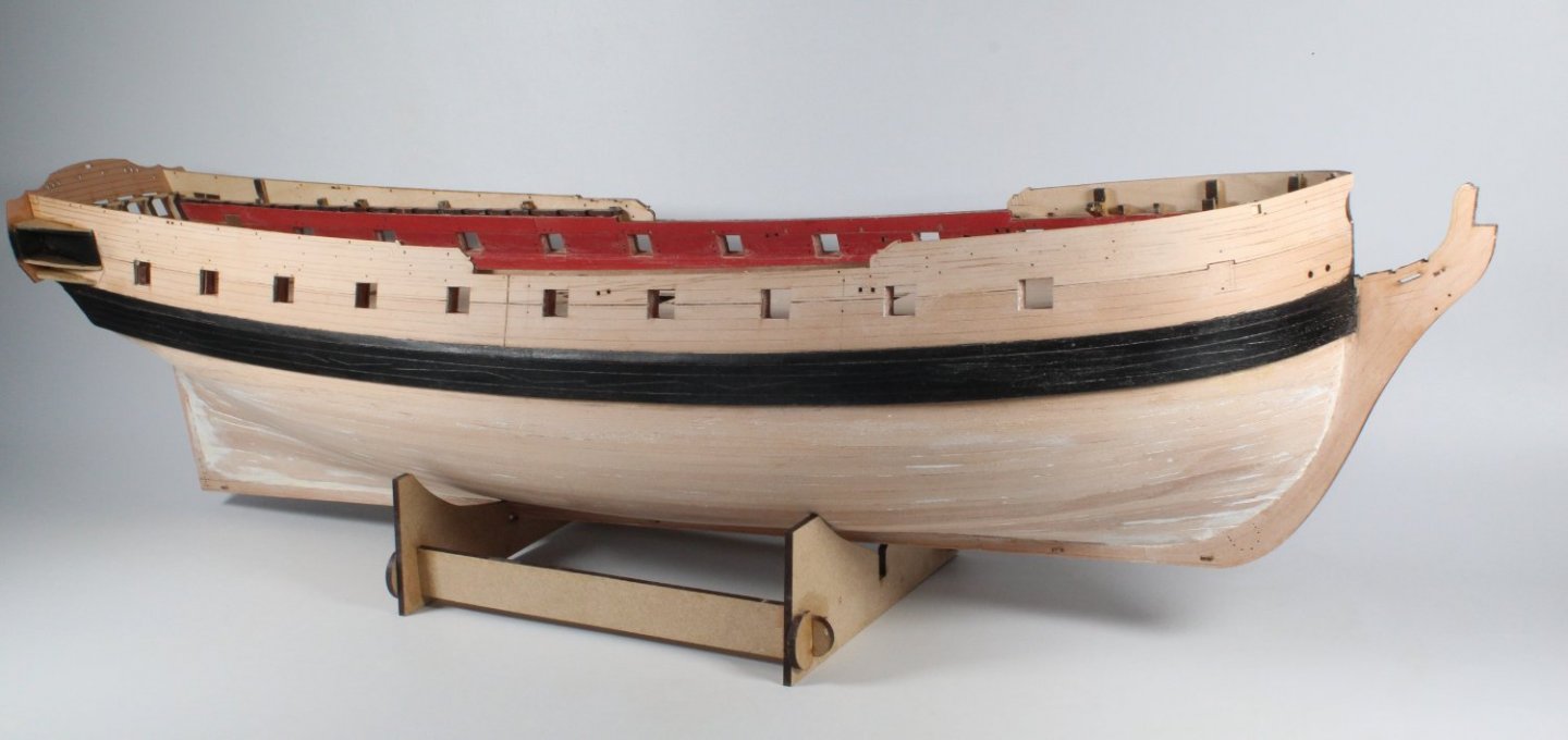
Painting The Wales and Strakes I decided to use the same Plastikote Black spray paint as used on the prototype, and as shown in the build manual. The first task was to prepare the hull. I started with some 4mm tape to mask above and below the wales and strakes. The tape was pressed firmly into place using a steel rule. I then used copious quantities of 50mm masking tape to cover the rest of the hull, leaving middle section of the quarter gallery open also. Finally a coat of wipe on poly was added to the wales and strakes. The hull was then taken to my garage when I sprayed the hull with the Plastikote Black paint. 3 light coats of paint were applied. Once the paint had dried I applied a wipe of poly coat to seal the paint finish. In the photo of the right-hand side below there is a bit of leakage below the hawse holes. This is not an issue as this area will be coved by the hawse bolsters later on in the build process. This is the left-hand side There is a tiny bit of leakage around the quarter galleries but apart from that it looks OK.

- 476 replies
-
- 9
-
-
- sphinx
- vanguard models
- (and 1 more)
-
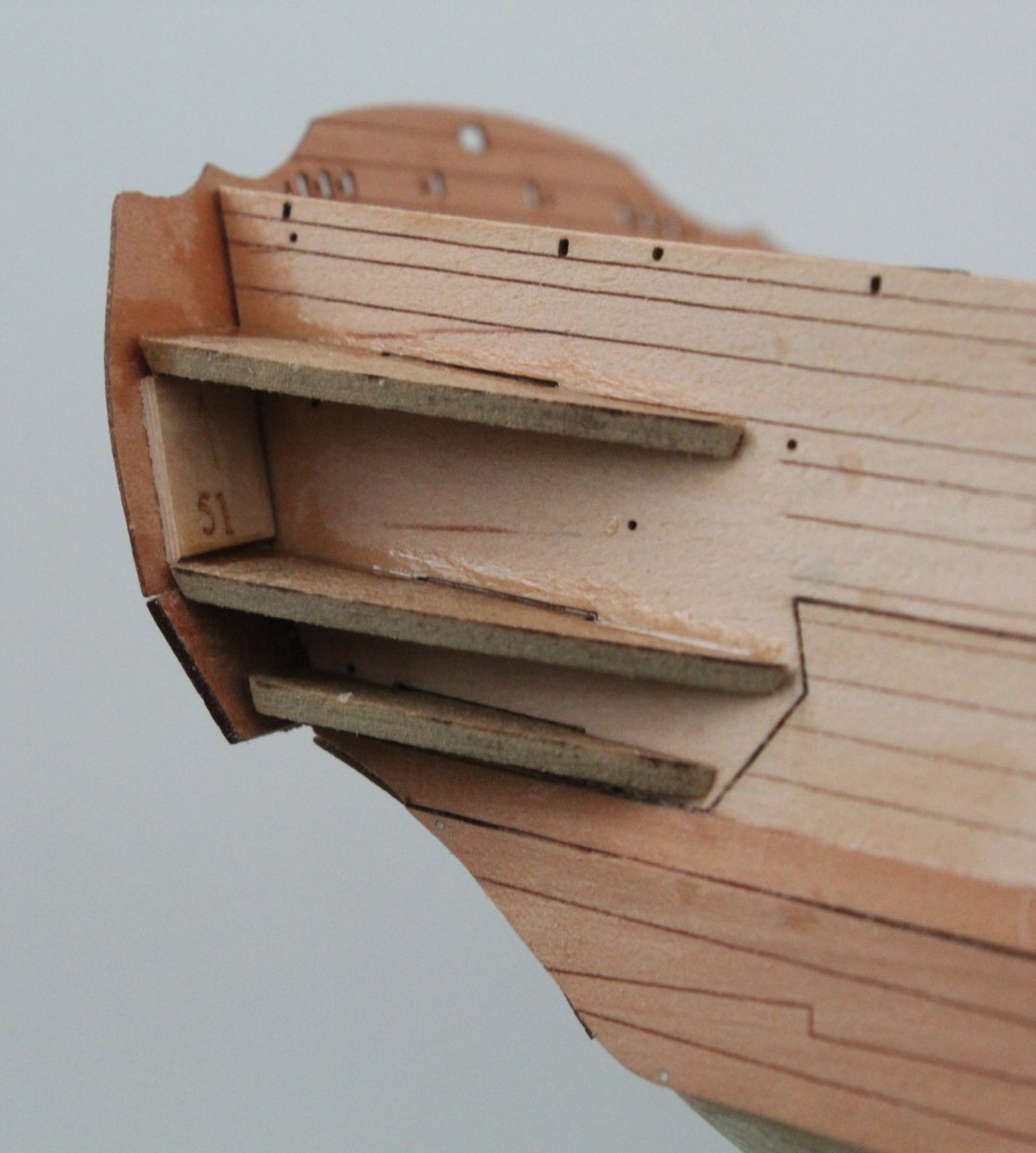
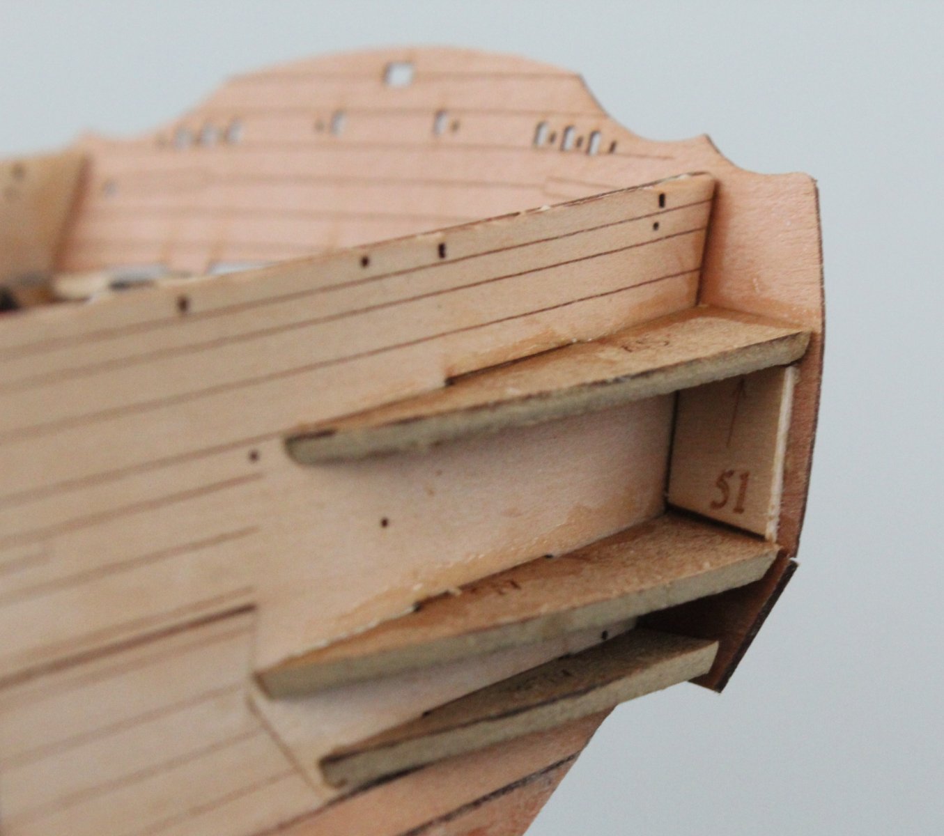
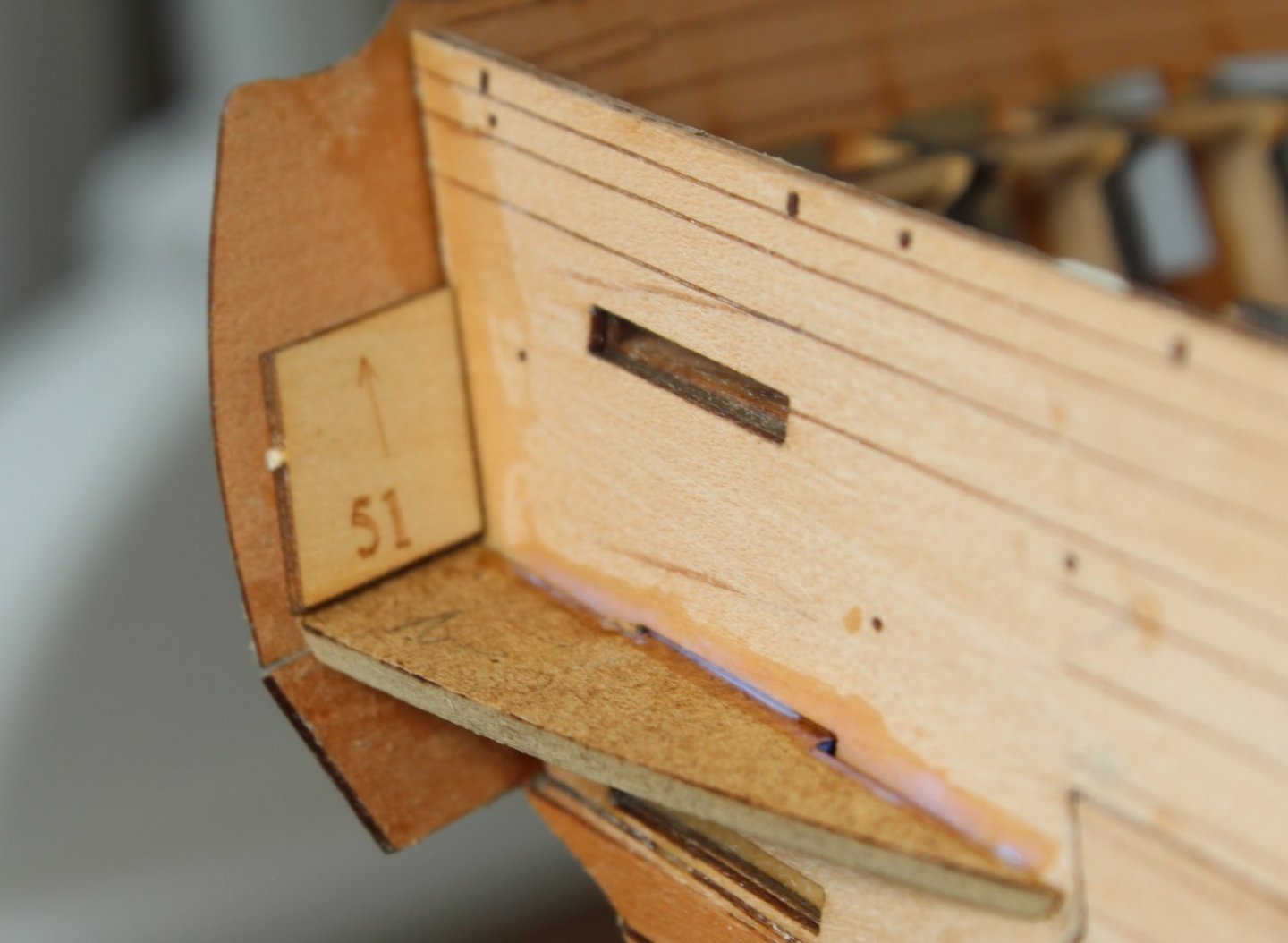
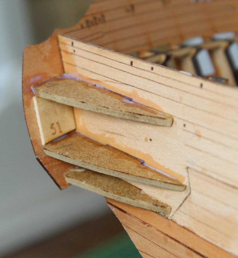
Quarter Gallery Patterns This was a nice task to undertake today. The 6 quarter gallery patterns were shaped, doing plenty of test fitting as I went along. Once I was happy with the fitting I started with the right-hand side and glued the middle pattern together with the alignment pattern 51 to ensure the pattern was properly set. Next the upper pattern was fitted and aligned with part 51. The task was complete when the bottom pattern was glued in place. The above process was then repeated for the left-hand side.


- 476 replies
-
- 12
-
-
- sphinx
- vanguard models
- (and 1 more)
-
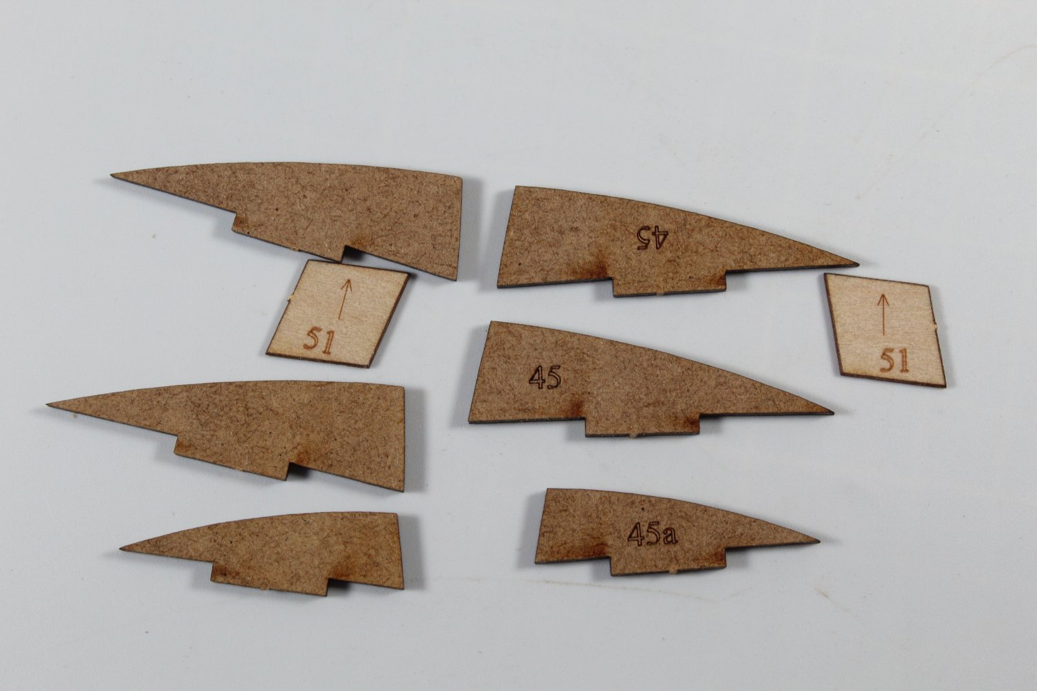
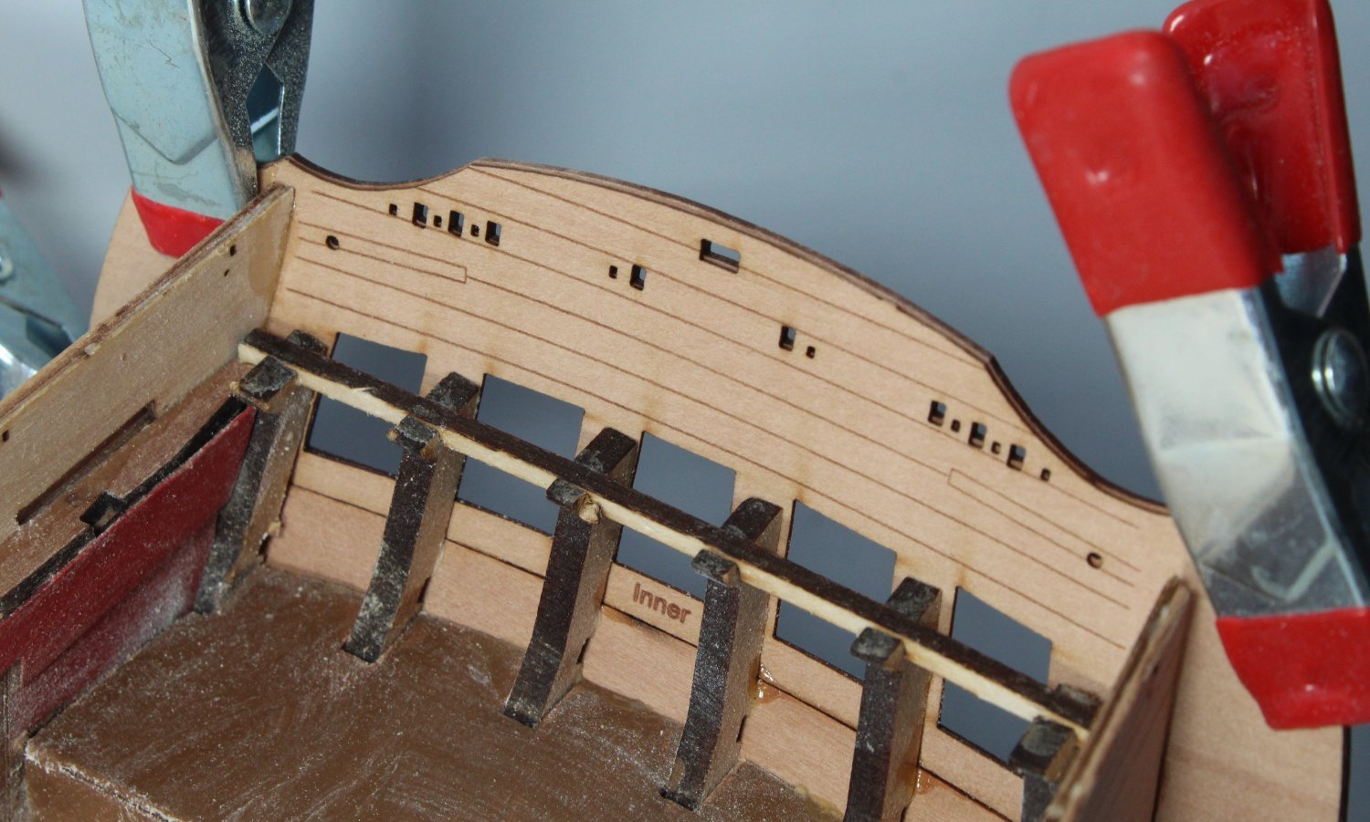
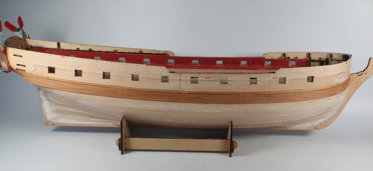
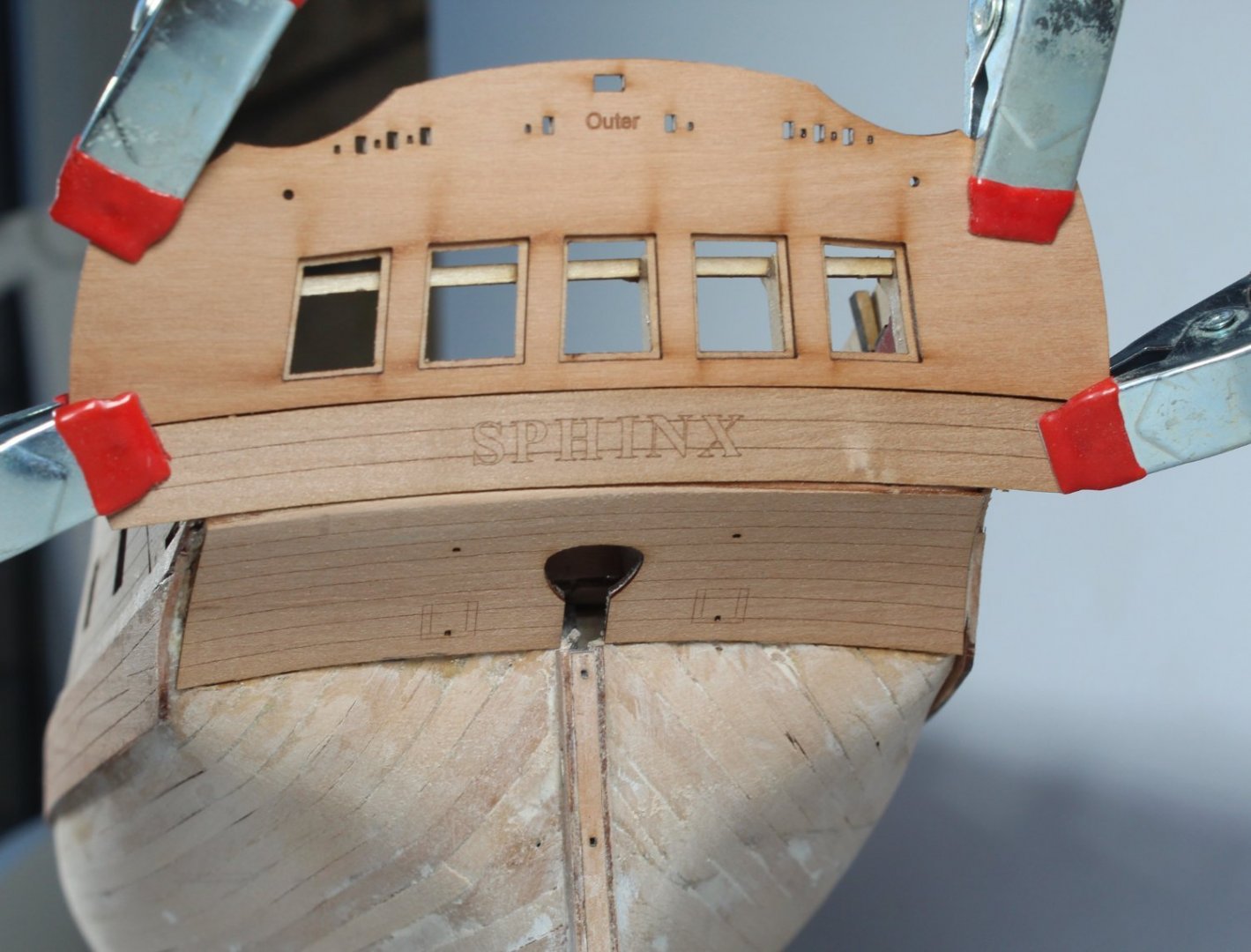
Main Wales & Strakes Take 2 Taking much more care the replacement main wales were glued in place. This time I made sure the top edge followed outer pattern from bow to stern. The upper strakes were also glued in place. I am much happier with how they look this time around. I have also fitted the upper counter pattern (inner) and inner fascia (inner). As can be seen in the photo below the fascia top edge alignment is approx. 2 mm above the bulwark. I have also dry fitted the outer upper counter pattern and stern fascia pattern. I am very pleased with how the stern area looks as can be seen below. The next task will be to shape and fit the quarter gallery patterns, 45 (x2) and 45a (x1) per side along with part 51 which is used to ensure the upper two patterns are properly angled.

- 476 replies
-
- 8
-
-
- sphinx
- vanguard models
- (and 1 more)
-
Thanks Tom There are many different ways to achieve the end goal. I have learnt so much by using other people's method detailed in their posts.
- 476 replies
-
- 3
-
-
- sphinx
- vanguard models
- (and 1 more)
-
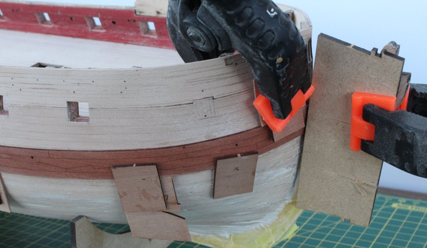
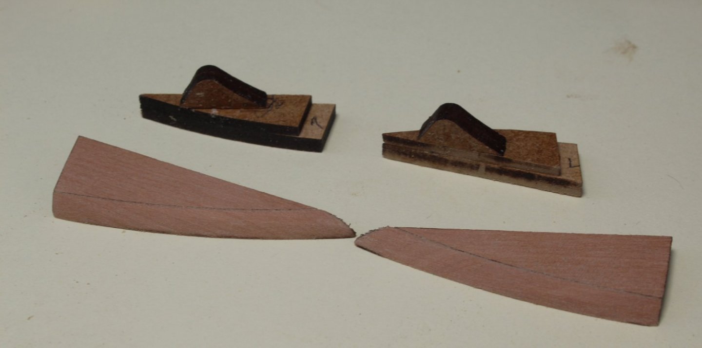
Fitting the Main Wales Take 2 One of the problems I had the first time around was ensuring the main wale was held in place whilst it was drying out during the bend process and when it was being glued. I ended up drilling some larger holes along the lower edge of the main wale so I could use map pins to hold the main wale in place as the glue cured. This time around I am experimenting with different approach. Using some offcuts from the main wale sheet I glued a support piece on top with an overlap to provide a clamp with a locating edge. The idea behind this is the top support piece will be flush with the hull and top of the wale as the bottom piece is the same thickness of the main wale. A brass pin can then used to hold the clamp in place, using the pin holes already provided on the main wale. A bit of overkill maybe but it seems to work well for me. As can be seen in the picture below I also used these clamps for the top edge The next photo shows the the entire right-hand side main wale held in place. At this stage this main wale had been soaked in hot water for 30 mins before being positioned and clamped. It will now be left to dry overnight before it is glued in place. I think this method works quite nicely so I will make a few more clamps this afternoon so I can repeat for the left-hand side also.

- 476 replies
-
- 7
-
-
- sphinx
- vanguard models
- (and 1 more)
-
Thanks. I do use my fingers quite a bit when sanding. I have discovered that cleaning the dust off with a damp brush also helps to highlight the flaws.
- 476 replies
-
- 3
-
-
- sphinx
- vanguard models
- (and 1 more)
-
I have been using my fingers to check the hull. I also use one of my camera's portable LED lights, which I find works really well in the evening. I'm not over the finishing line just yet as I know there is plenty more work required. That said this is the best I've planked a hull. I'm still not very good at it, but I am getting better at planking with each build.
- 476 replies
-
- 3
-
-
- sphinx
- vanguard models
- (and 1 more)
-
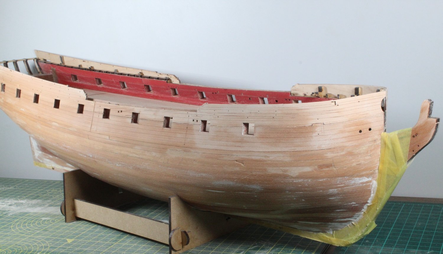
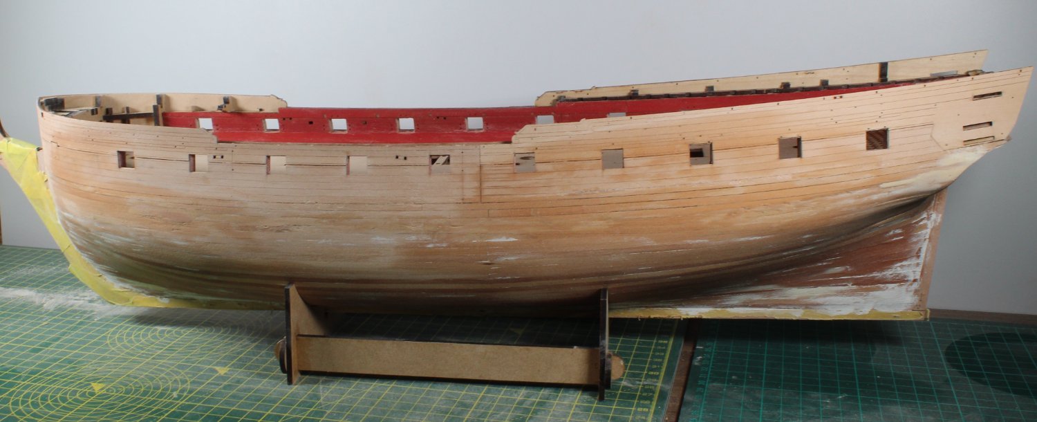
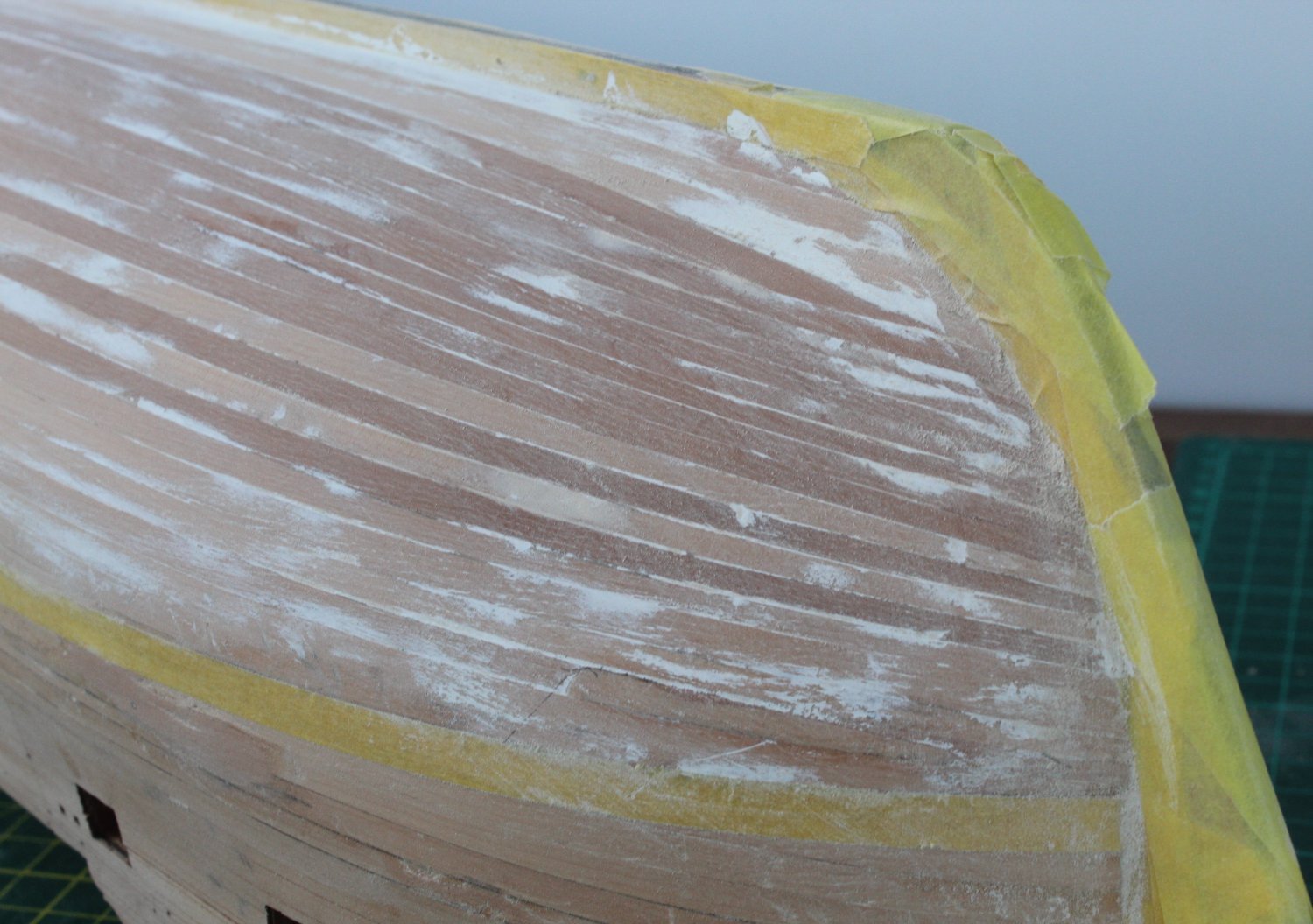
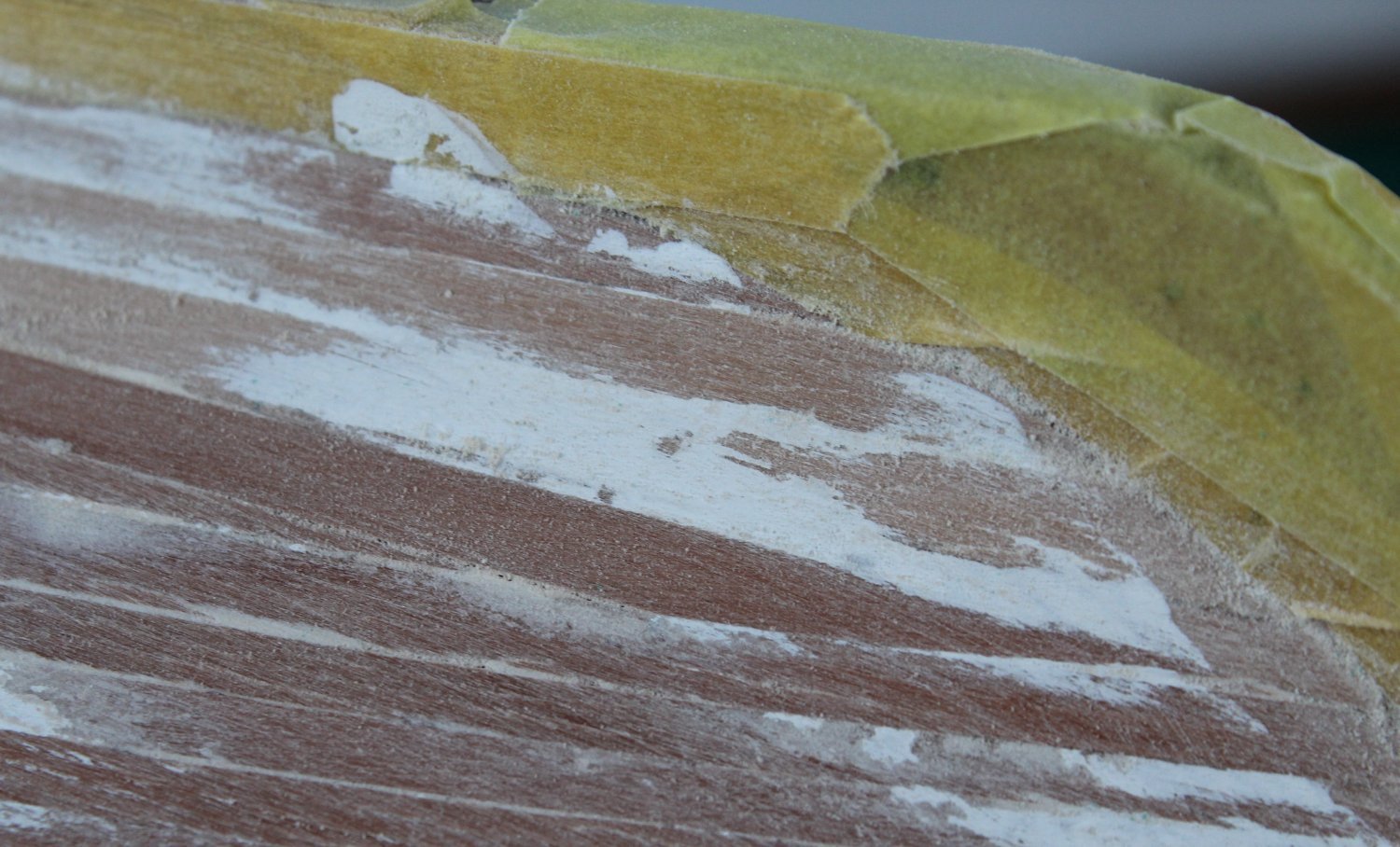
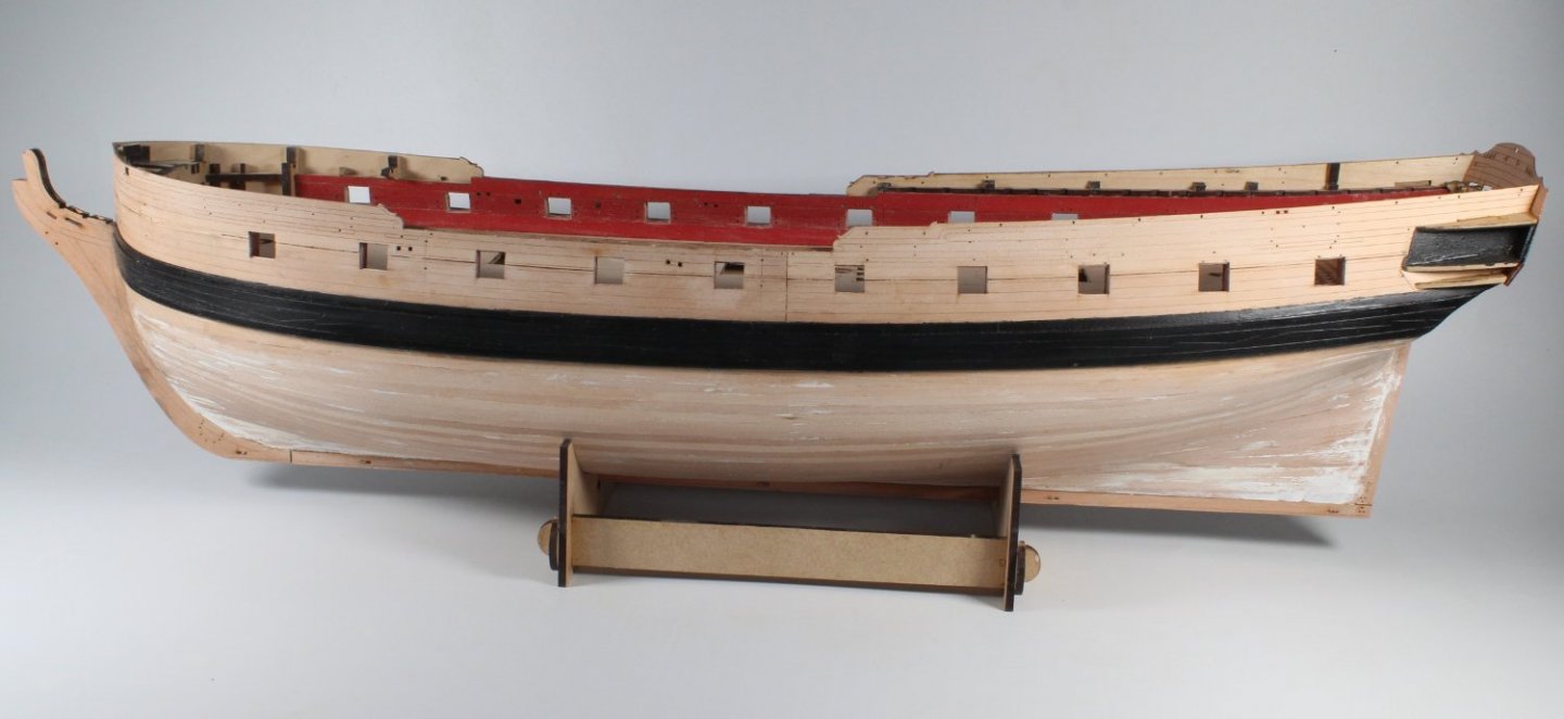
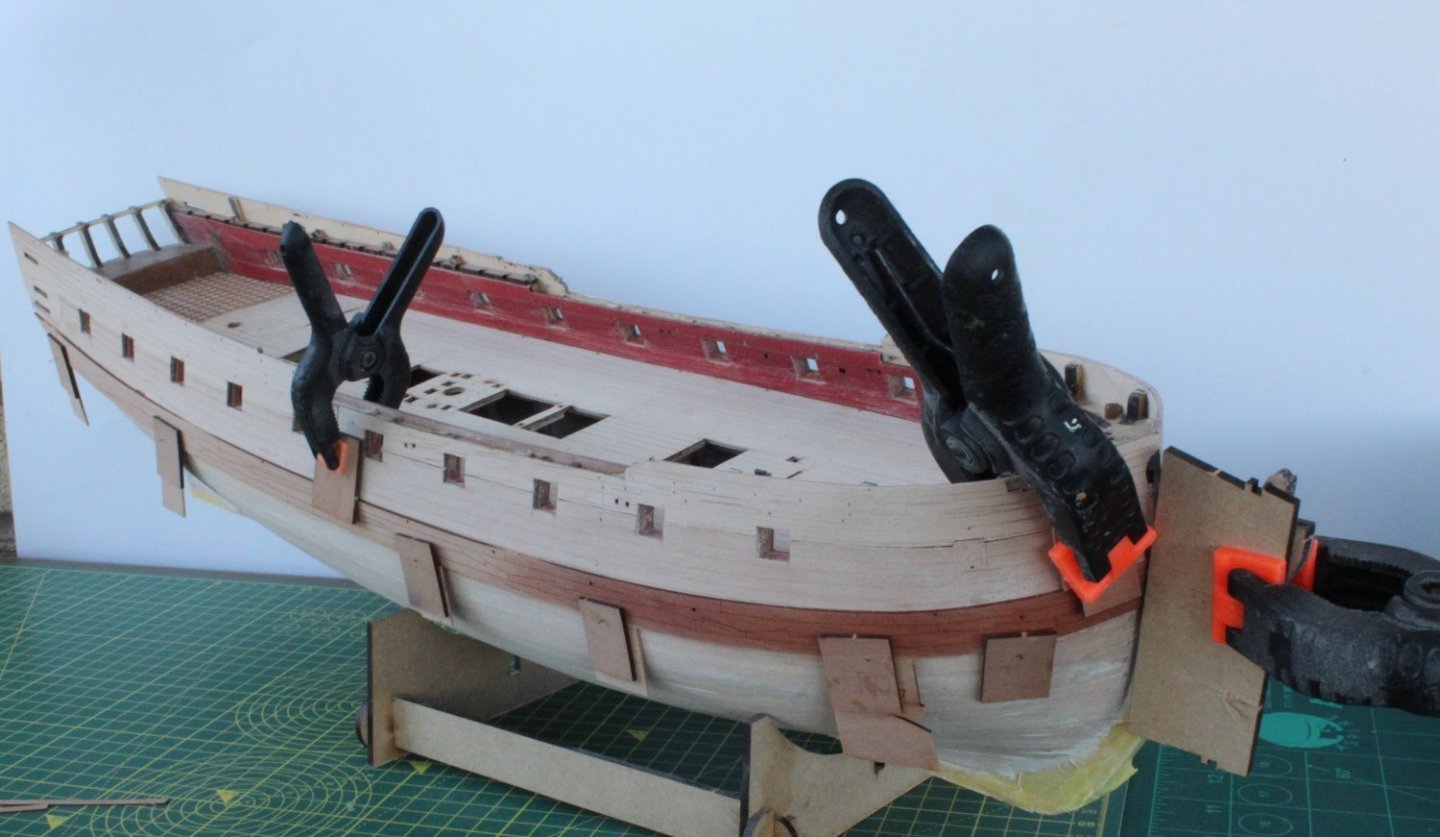
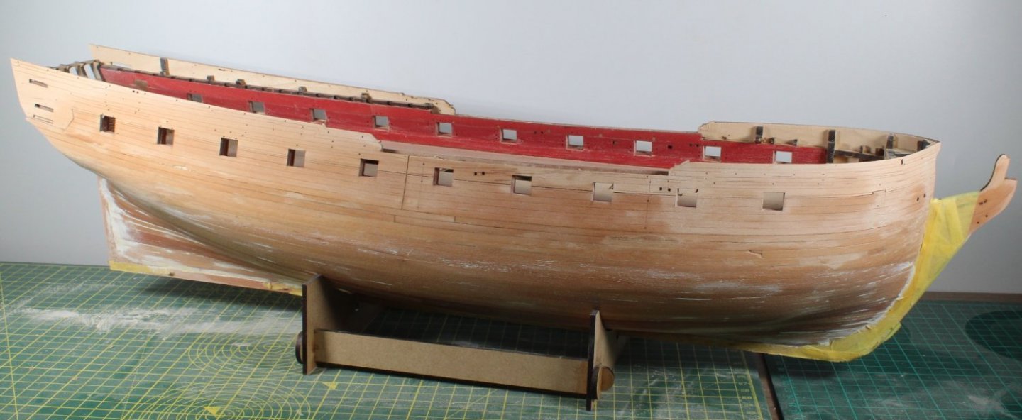
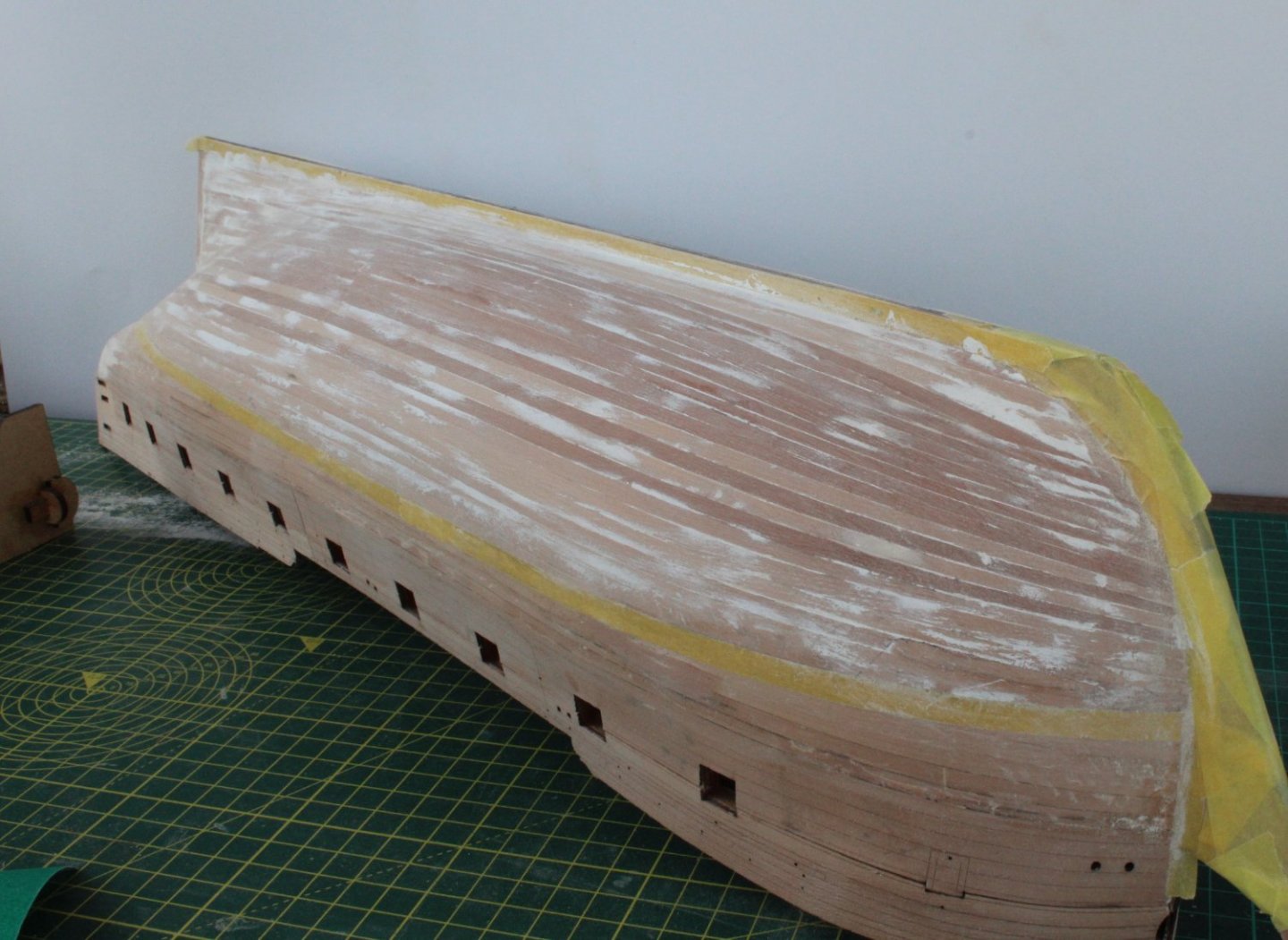
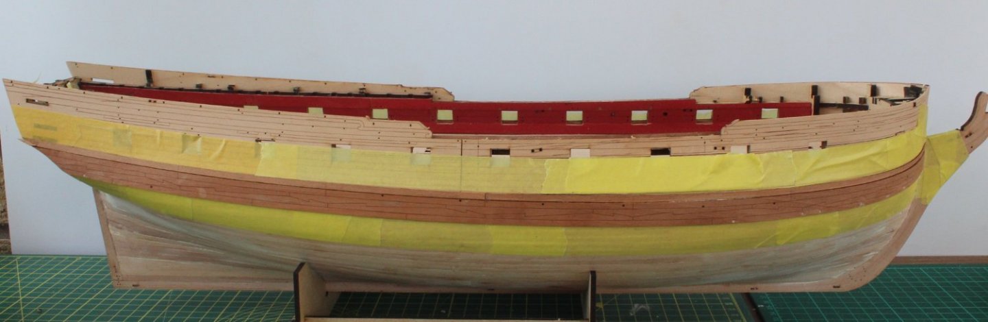
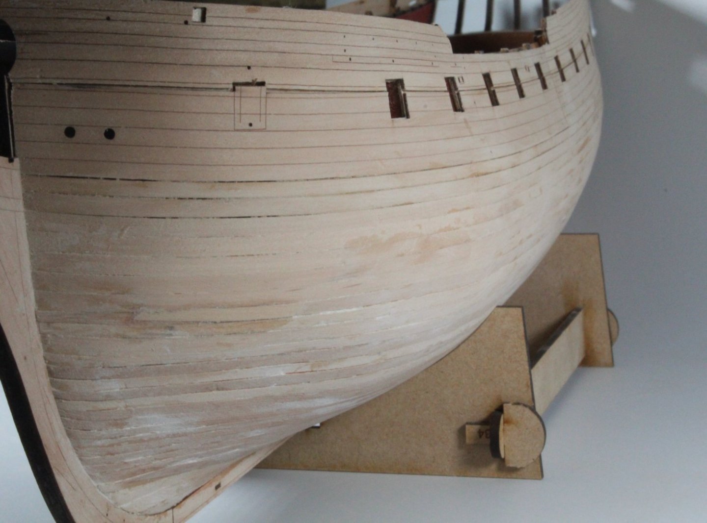
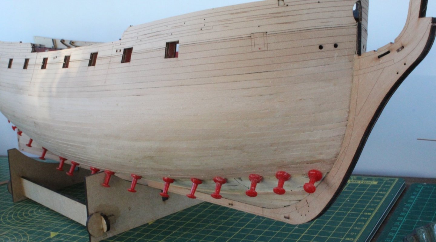
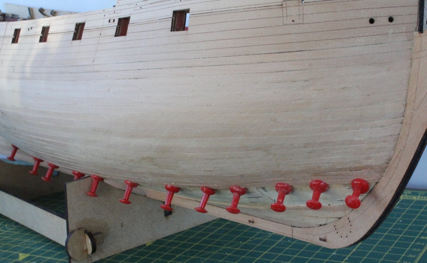
The hull has now been painted, filled and sanded a couple more times. I am now reasonably happy the hull is smooth for the most part and I think the hull is ready for painting. I am sure the hull will require more sanding and filling as the painting coats are applied (and not sanded away). The replacement main wales and strakes arrived today so tomorrow I plan to bend the main wales to the required shape so they can be glued in place, this time making sure I align the wales correctly. Here are some pictures of the hull. I did brush the hull with a damp brush to hull remove the sanding dust, hence the colouration effects visible in the photos.


- 476 replies
-
- 11
-
-
- sphinx
- vanguard models
- (and 1 more)
-
Thanks for the information. I know from my V1 build it took me a few days of painting, sanding and filling to get a nice looking finish. The V2 hull has had it's first coat of paint, which has been sanded away to show areas which then required filling. Filler was then added to the depressions and then sanded smooth. I will continue to repeat this process until I'm happy with how the painted hull looks.
- 476 replies
-
- 2
-
-
- sphinx
- vanguard models
- (and 1 more)
-
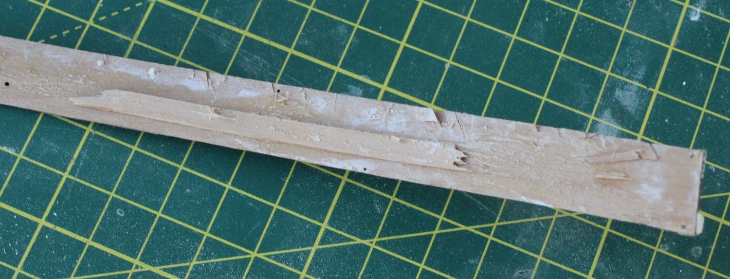
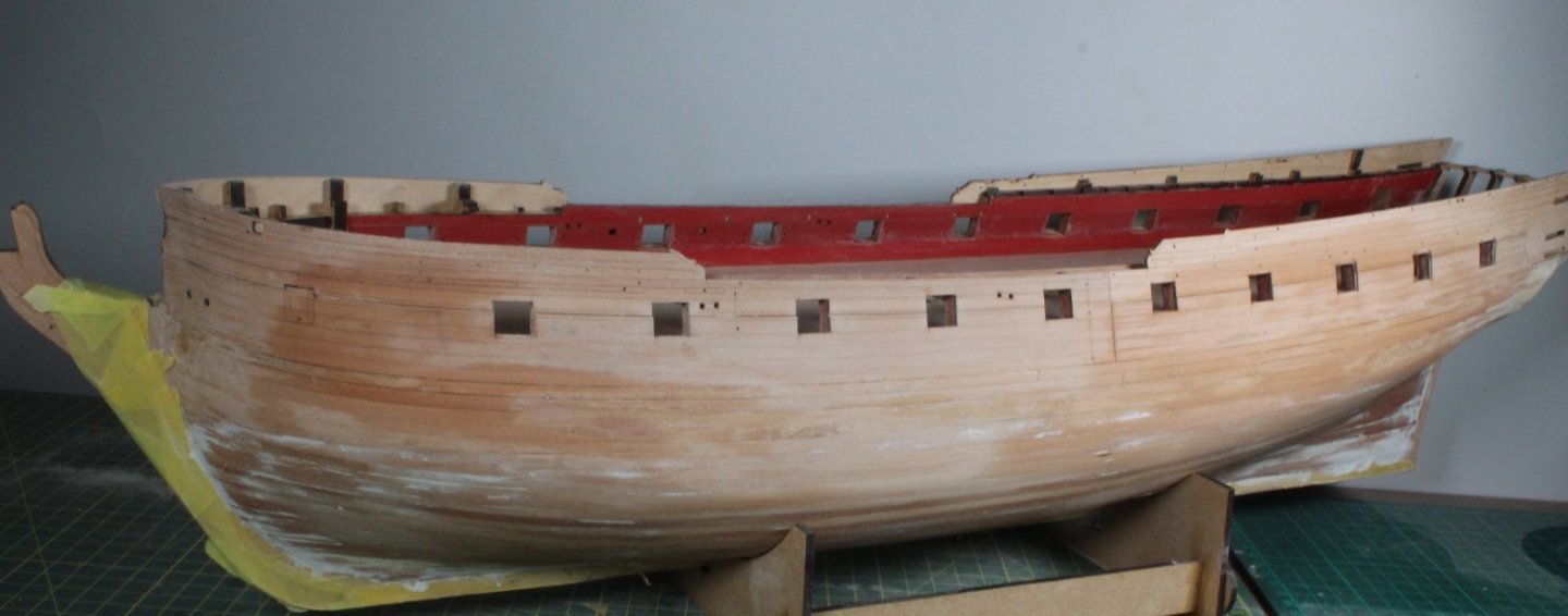
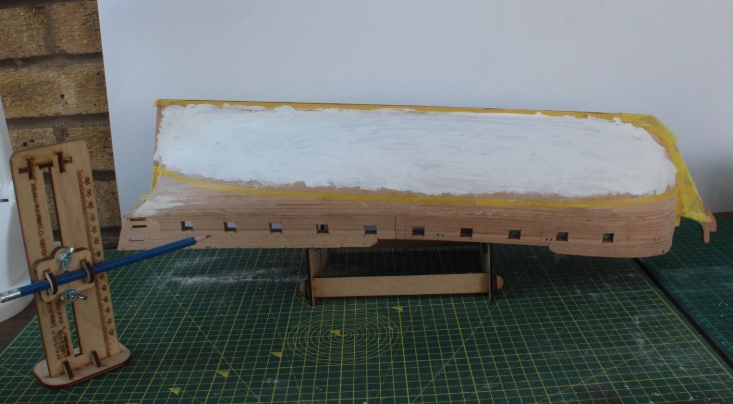
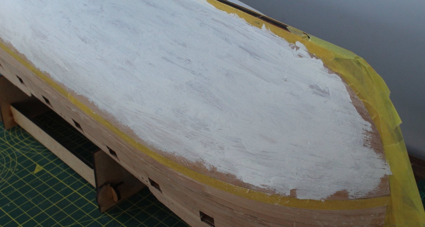
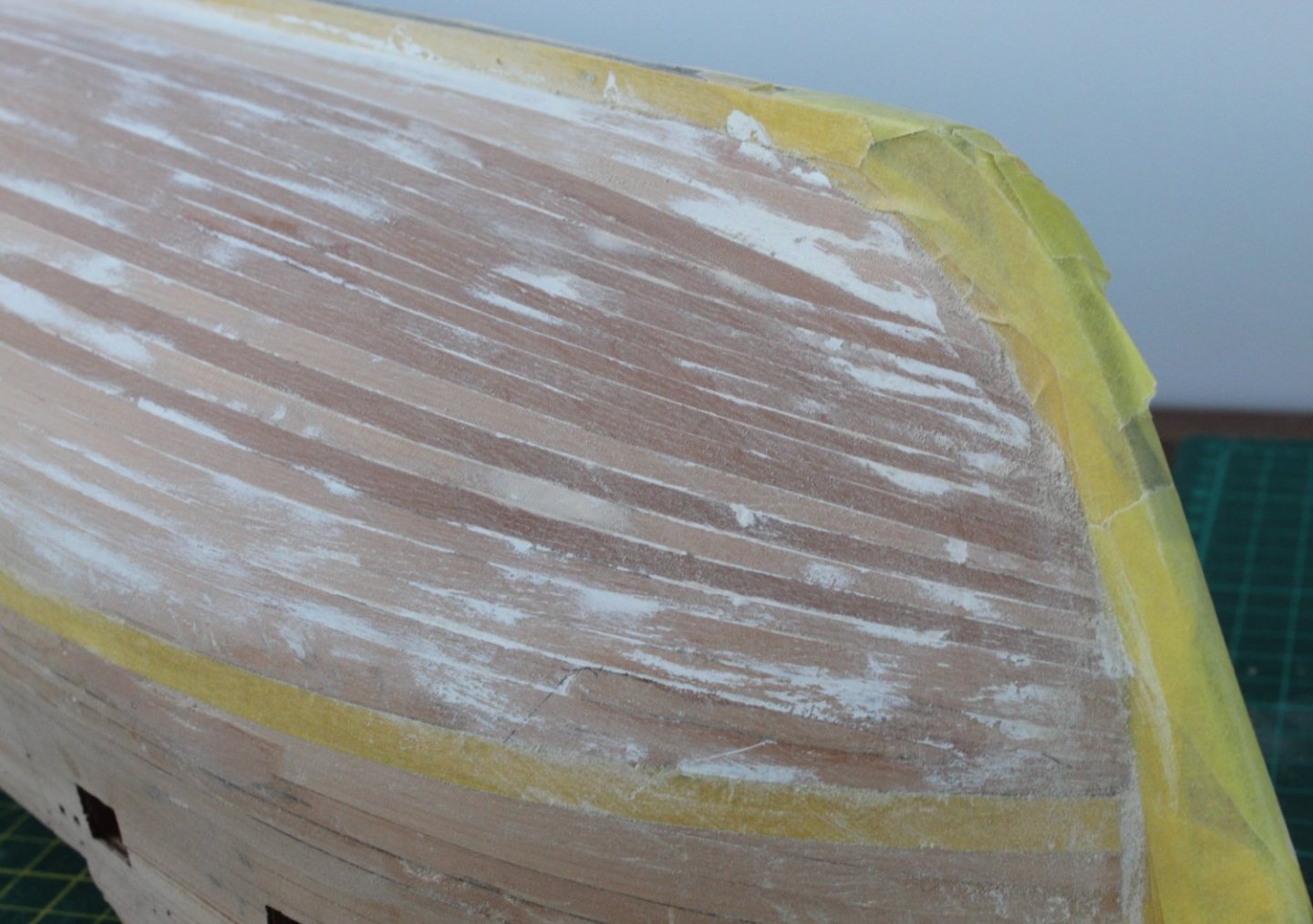
The replacement main wale and strakes I have ordered from Chris are due to arrive tomorrow. It did take a lot more effort than I expected to remove the main wales and strakes from the hull. As can be seen in the photo below the hull did suffer a little bit of damage in that some of the 2nd planking also came away with the main wale. Thankfully it was a very easy repair. Whilst I wait for the UPS delivery I decided to start the first stage of preparing the hull for the white paint. I started this process by applying a coat of white paint to the hull, ensuring I had taped the hull. I really like the waterline marker tool, which I purchased from Vanguard Models. I decided not to go to mad and did not apply paint all the way to the taped waterline. Once the paint had dried it was time to sand the paint away, noting that any depressions in the hull construction would still contain traces of the white paint. The next few photo's show the left-hand side. I have not as yet sanded the right-hand side. Based on the first pass of painting and sanding I think the left-hand side will look pretty good once the process has been completed. There is one area on the bow which will require a bit more attention to get a nice smooth line, as shown below. I know from my V1 build, and from reading the manual (and Jim's excellent build log) there will be plenty more work required applying paint and sanding/ filling before I end up with a nice smooth painted hull.


- 476 replies
-
- 6
-
-
- sphinx
- vanguard models
- (and 1 more)
-
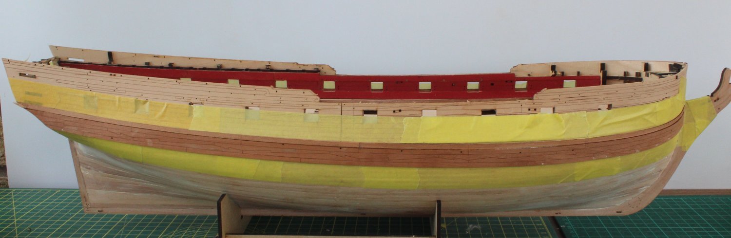
The next task on the build agenda was to fit the main wale and strake. I started this process by soaking the main wale (left and right) in hot water for 30 minutes. The wales were then positioned on the hull to allow the wales to dry for 18 hours so they could retain the bend around the bow area. With reference to the plan sheet I took great care to position the wale at both the bow and stern end. The wales were then glued in place, using Titebond original wood glue. The strakes were then fitted above the main wale, using ca gel. Next I taped above and below the main wale and strake and applied a coat of WOP (wipe on poly) in preparation for adding the black paint. So far so good. As I wiped on the poly the words "Houston we have a problem" suddenly popped in to my head. The stern area looked good, the strake was just a tad low at the stern, so no reason to be alarmed. However as I took a closer look at the midships I noticed the strake was actually drifting south of the guide line. As I then looked toward the bow the strake I noted the stake was now aligned with the line below the line used at the stern - dooh!!!!!!!! I have contemplated leaving as is no one else will see the model once complete so only I would really be aware of the error. But then I realised there were other knock on effects, such as the relative position of the bottom of the main wale with the waterline would be wrong, as would the fitting of the chain plates. Therefore I know I have to remove these parts and redo. As I started to gently ease the main wale away from the hull (using water to soften the wood glue) the main wale started to split. I do not think I will be able to salvage and reuse. I did think about making new wales using 1mm planks and strakes using 0.6mm planks but as I really like the laser etched pattern on the wales I have ordered replacements. I will use some spare 0.6mm planks to replace the strakes.
- 476 replies
-
- 6
-
-
- sphinx
- vanguard models
- (and 1 more)
-
It is interesting to note you have fitted the first stay before the shrouds. I know the normal method, as detailed in the build manual, is to fit the shrouds before the stays. Glenn (UK)
- 542 replies
-
- 1
-
-
- Sphinx
- Vanguard Models
- (and 3 more)
-
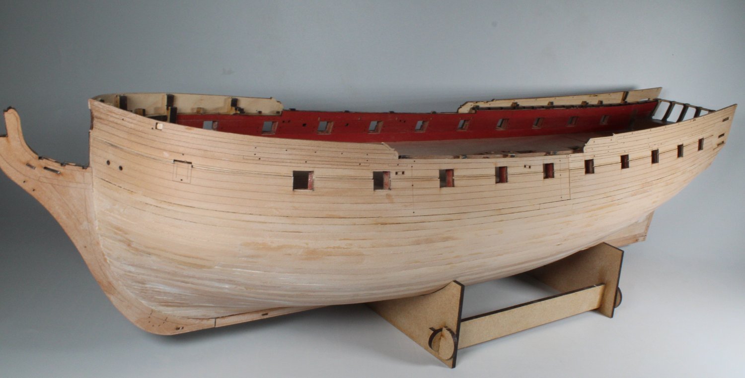
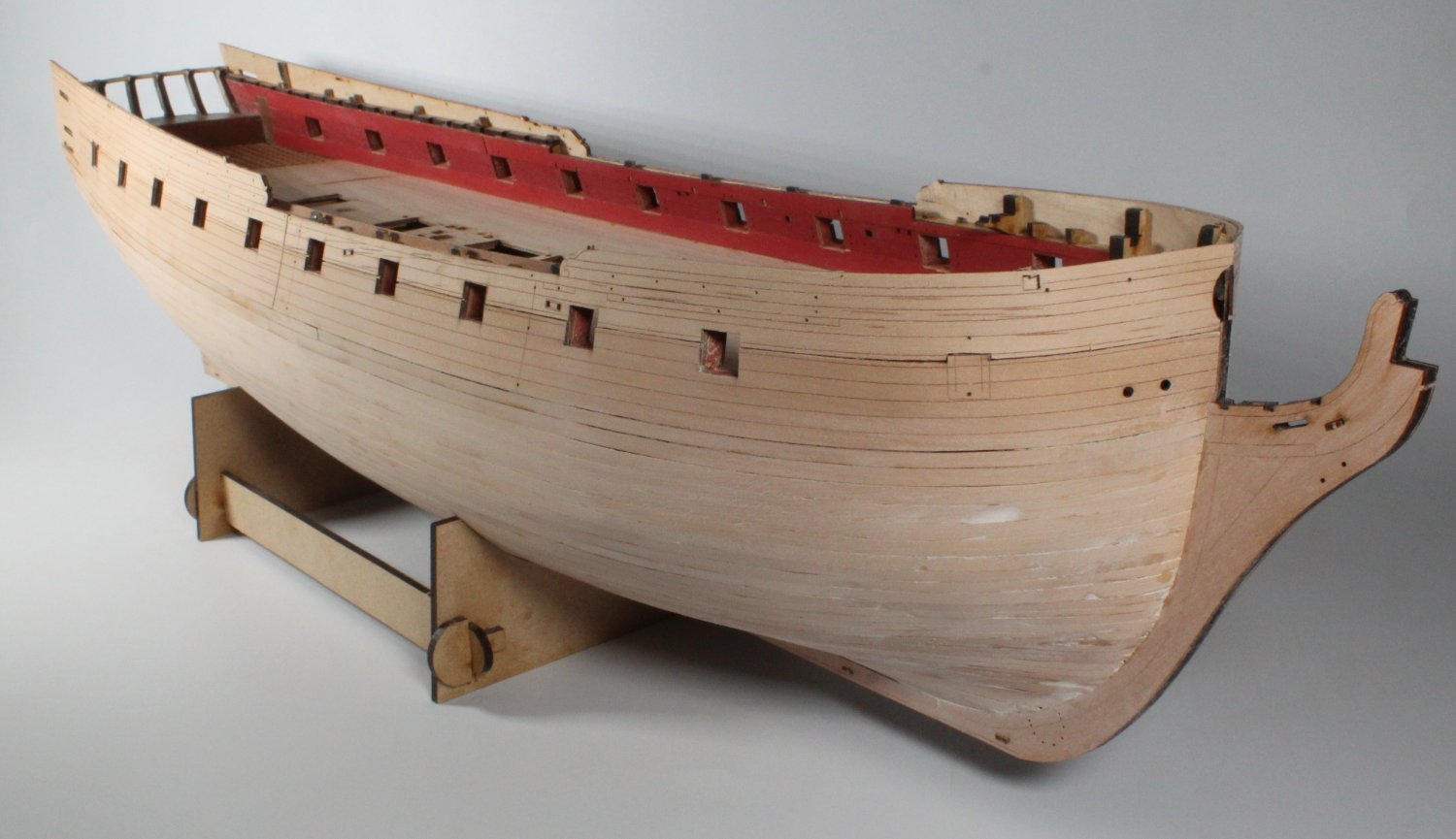
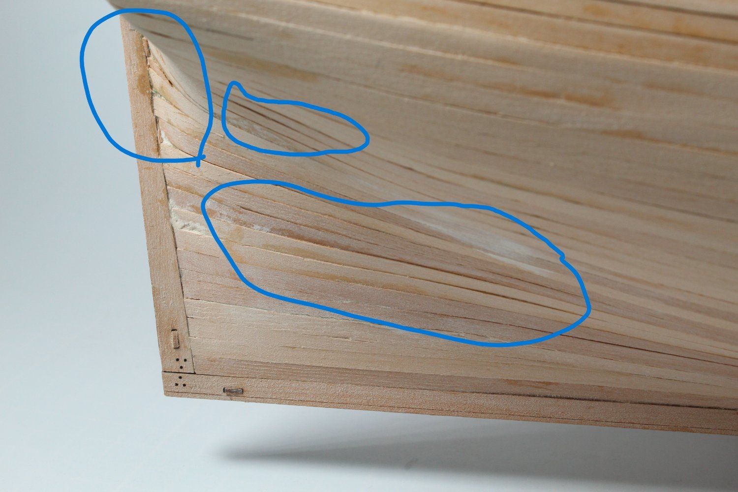
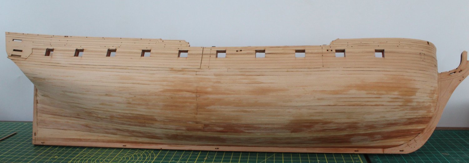
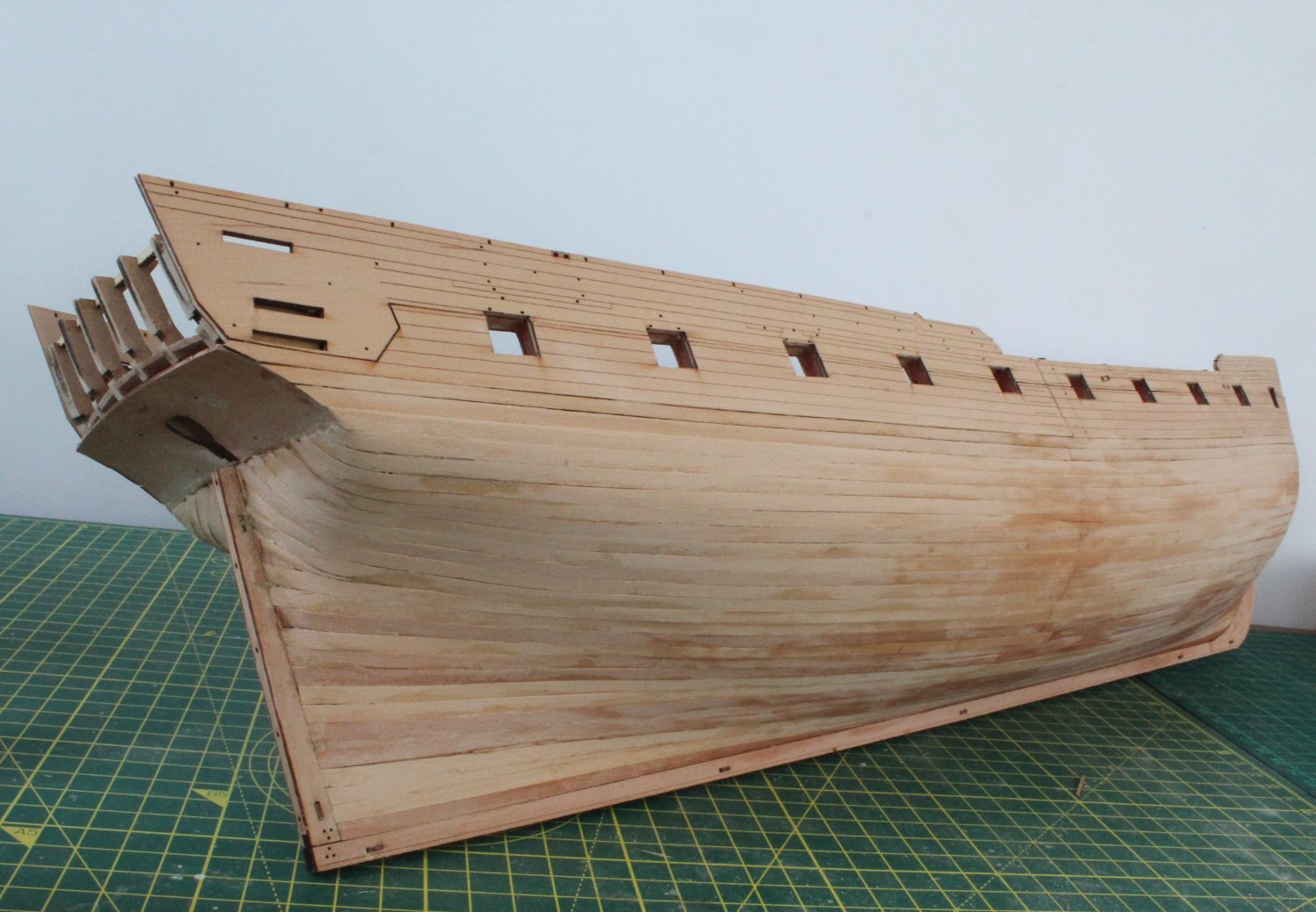
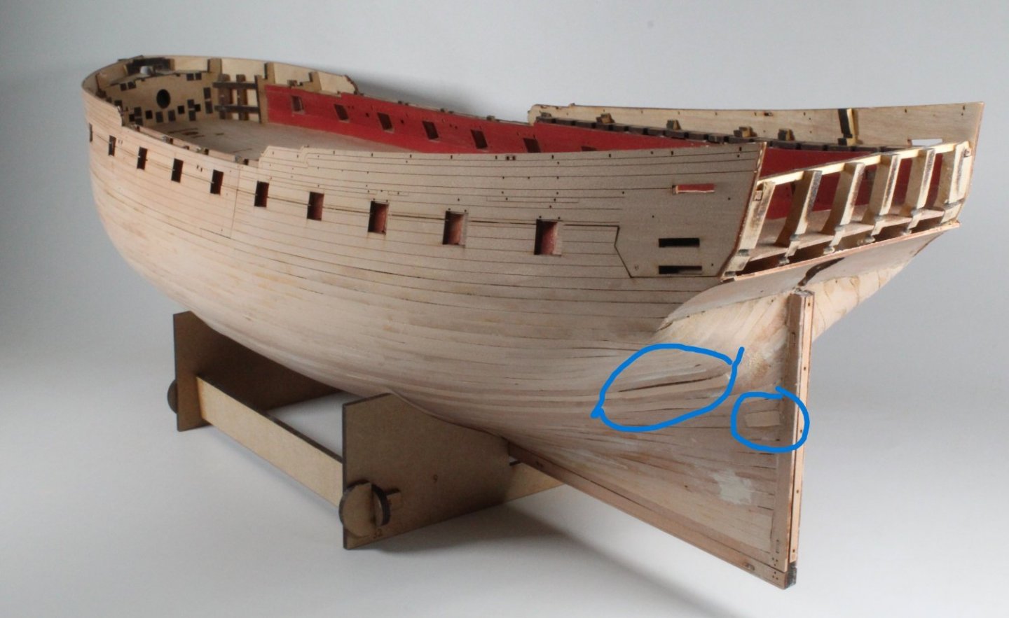
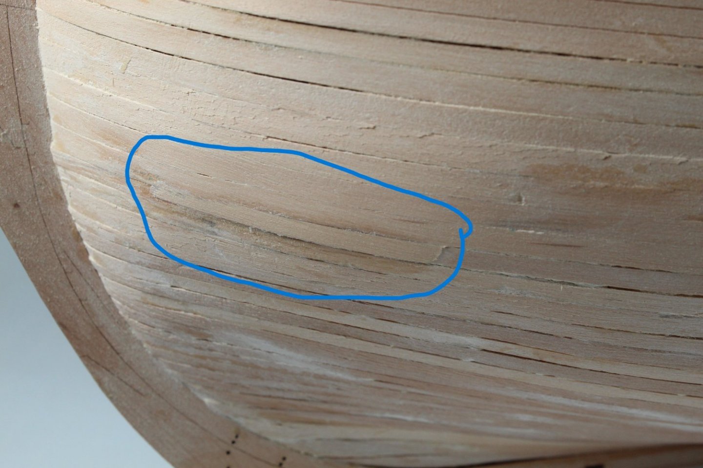
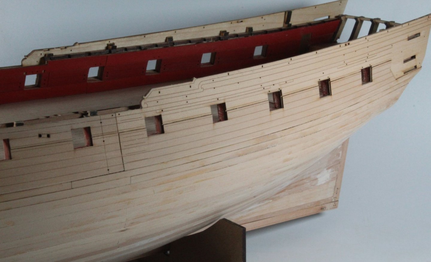
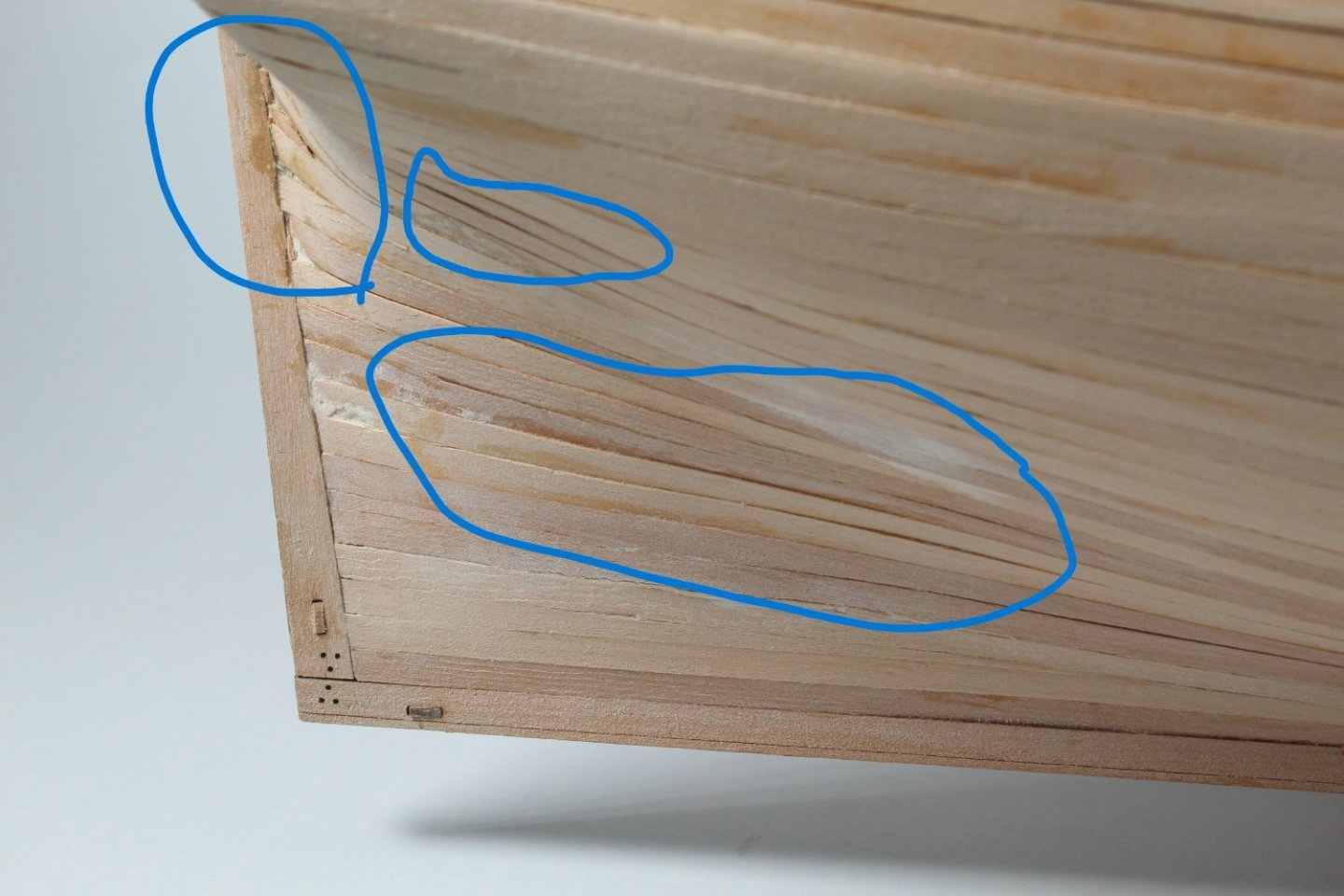
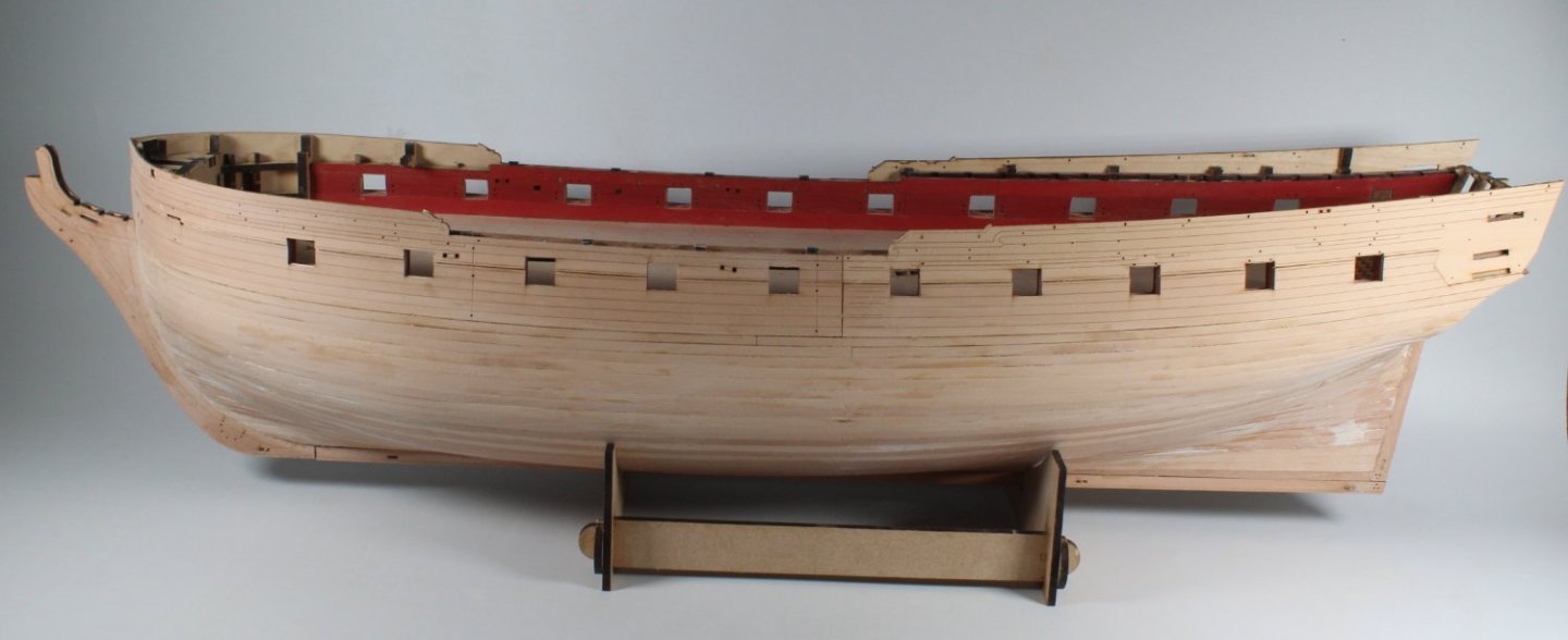
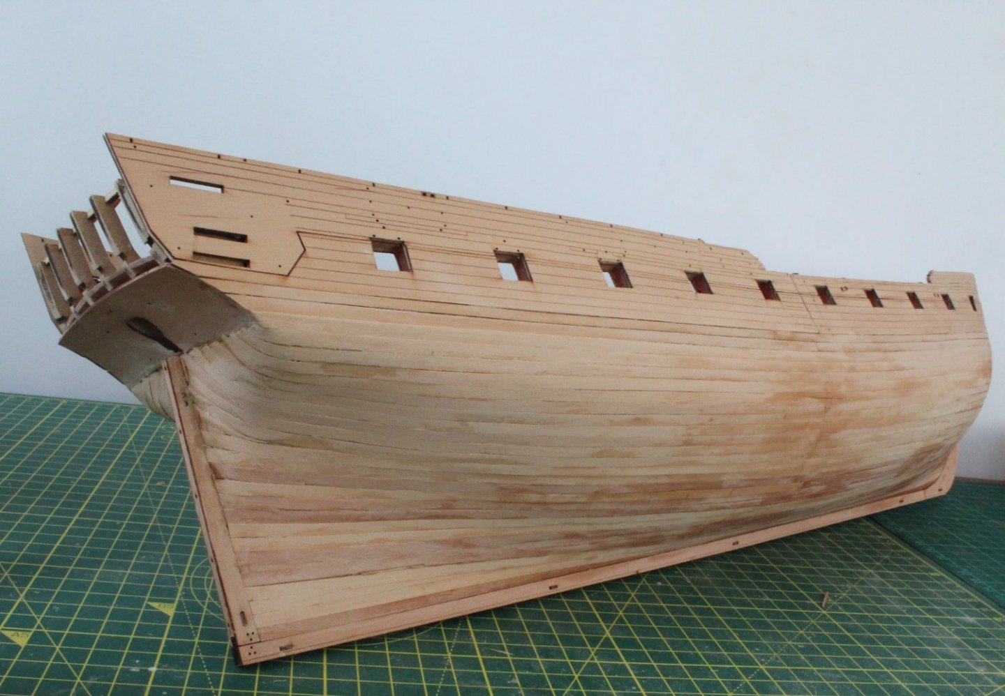
I have made good progress since my last post and I have now completed the 2nd planking. I will start off by showing a couple of pictures showing the completed hull which will then be followed with a bit more detail of the work required to correct some of the defects with the 2nd planking. The first two photo's show the completed left-hand side The next photo shows the completed right hand side When looking at the bow area on the left hand side there was a depression. This could be filled by using a wood filler mixture but I opted to try fitting a planking veneer overlay. Using a short length of planking material which I sanded to reduce the depth before fitting. The next photo shows the veneer glued in place. With a bit of sanding it does not look too bad. A bit more work is still required to get a nice smooth finish but I am happy with using this process correcting the bigger depressions. Moving on to the stern area I have added a couple of filler veneers. A short length was used to correct a dip with the stern post joint. The other piece is an experiment to correct a dip highlighted by @chris watton in a previous post. It does seem to improve the flow of the stern area so if I carry on with this method a few more veneers will be required. I need to add the waterline to get a better idea of what will be required. The key will be to use veneers which will match the colour of the base planking strakes, above the waterline. The hull will be painted white below the waterline so colour matching is not necessary. I am happy with how the midship joints have turned out after a light sanding. The next picture has highlighted three areas on the right hand side stern area which will require quite a bit of work to get a nice smooth hull. These close up pictures really do magnify the planking defects and make them look far worse than they look to the naked eye. These area will be resolved using filler (stern post area) and sanding for the other two areas.


- 476 replies
-
- 6
-
-
- sphinx
- vanguard models
- (and 1 more)
-
Hello Glenn (USA). I am not too worried about structural integrity for the 2nd planking. I certainly would be staggering the joints if they were visible or load bearing. The joints were not visible on my v1 build after sanding and painting.
- 476 replies
-
- 3
-
-
- sphinx
- vanguard models
- (and 1 more)
-
These butt's are all below the waterline. The hull will be painted white below the waterline so the butt joints will not be visible.
- 476 replies
-
- 1
-
-
- sphinx
- vanguard models
- (and 1 more)
-
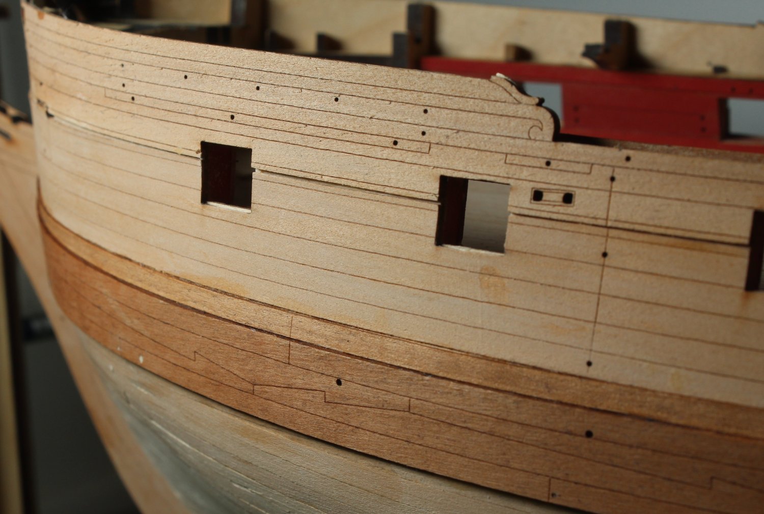
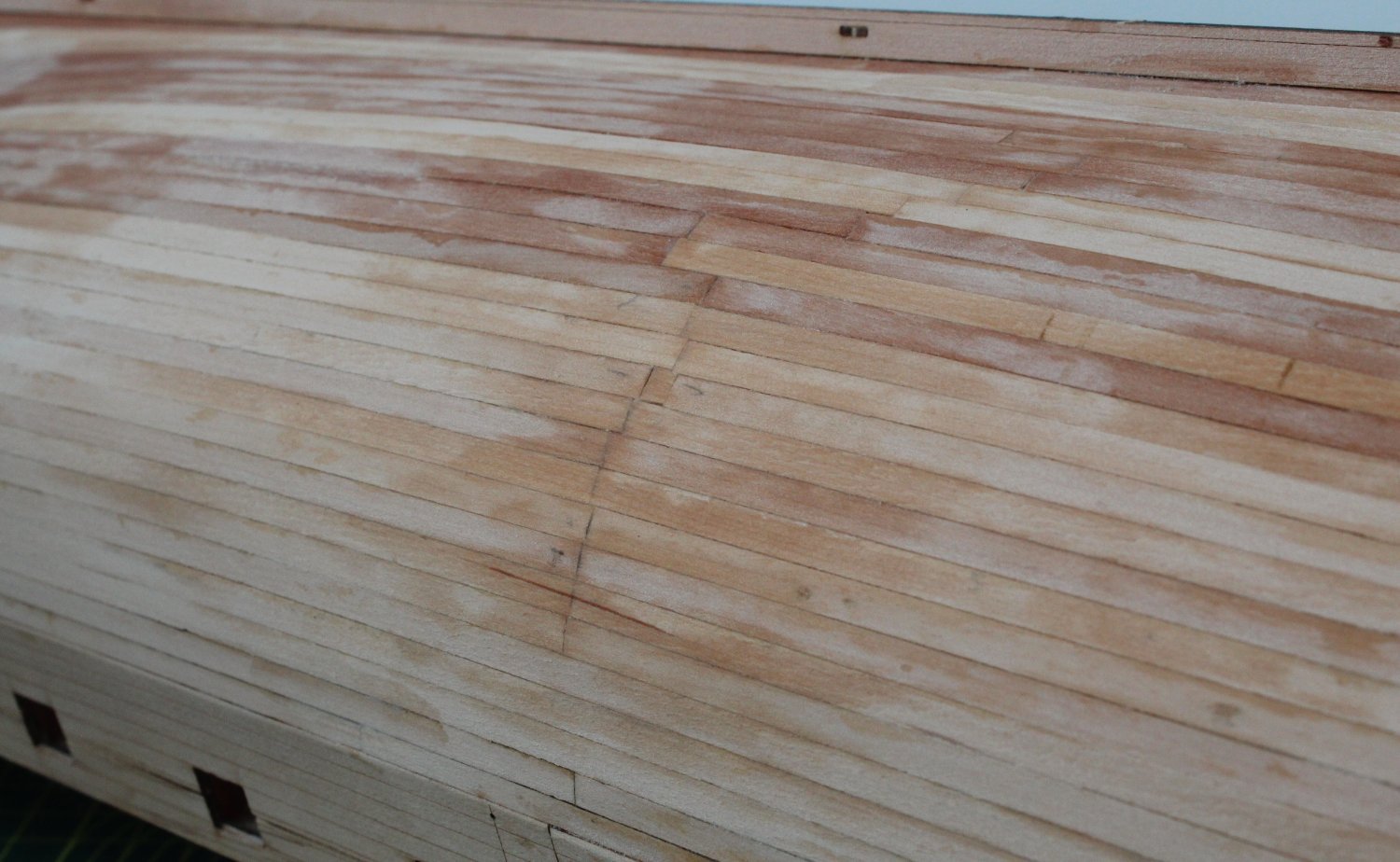
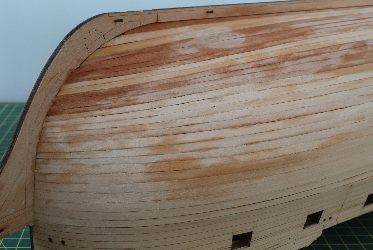
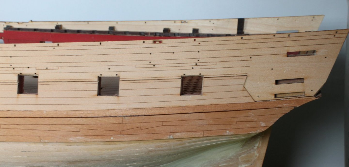
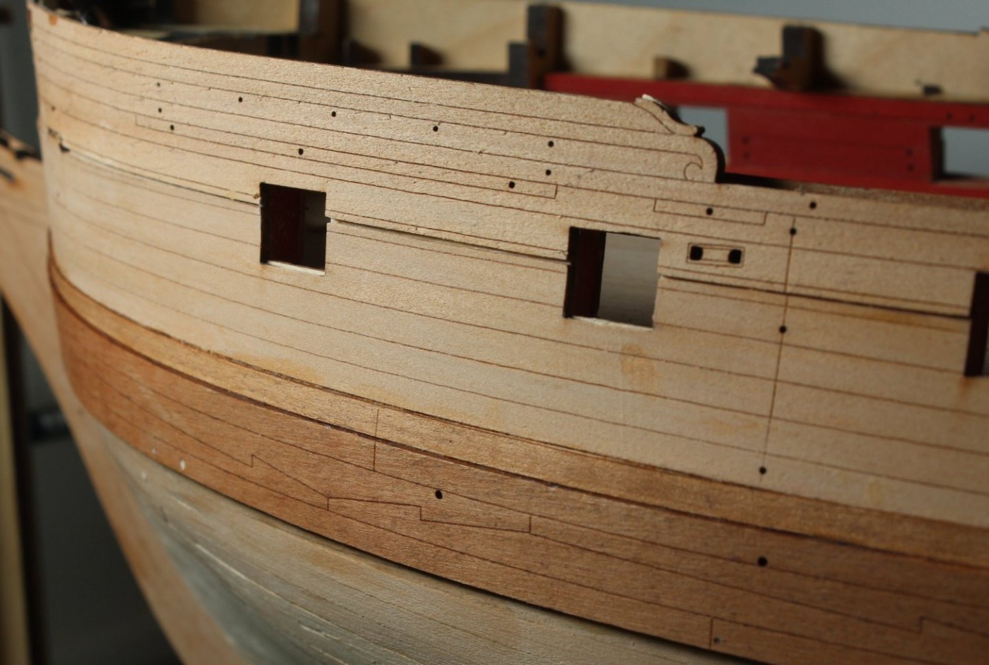
I have finally completed the 2nd planking on the right-hand side of my V2 build. I have approx. 10 planks left to fit on the left-hand side to complete this stage of the build, which should take me 3 or 4 days to complete. I have added a few photo's of the completed right-hand side. After completing the planking I did use a damp paint brush to clean up the surface, hence the blotchy nature of the hull in the ensuing photos. This is a close up of the bow area. Overall not too bad, but it will need sanding and filling to get a nice smooth surface for the painted area below the waterline. Close up of the stern area, this will require a lot more work to get smooth compared with the bow area. The next picture shows the midship plank joints, below the waterline.


- 476 replies
-
- 6
-
-
- sphinx
- vanguard models
- (and 1 more)
-
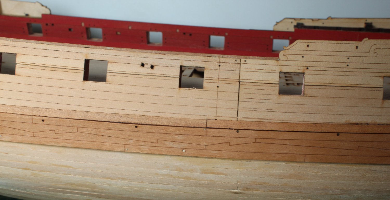
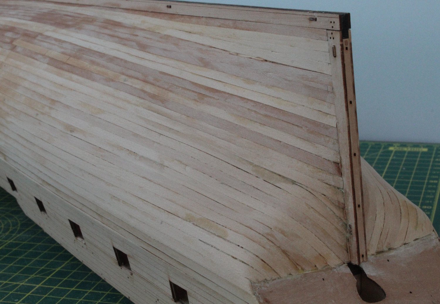
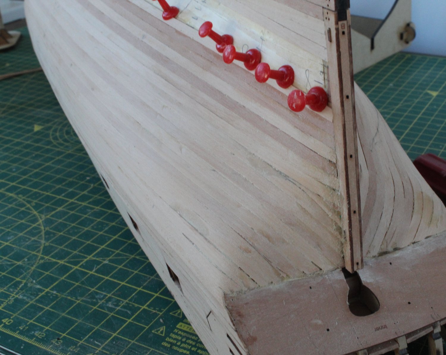
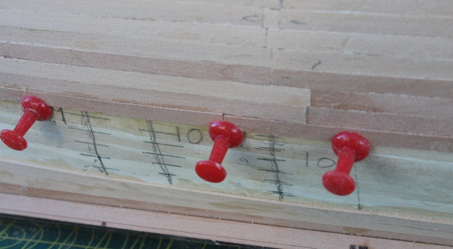
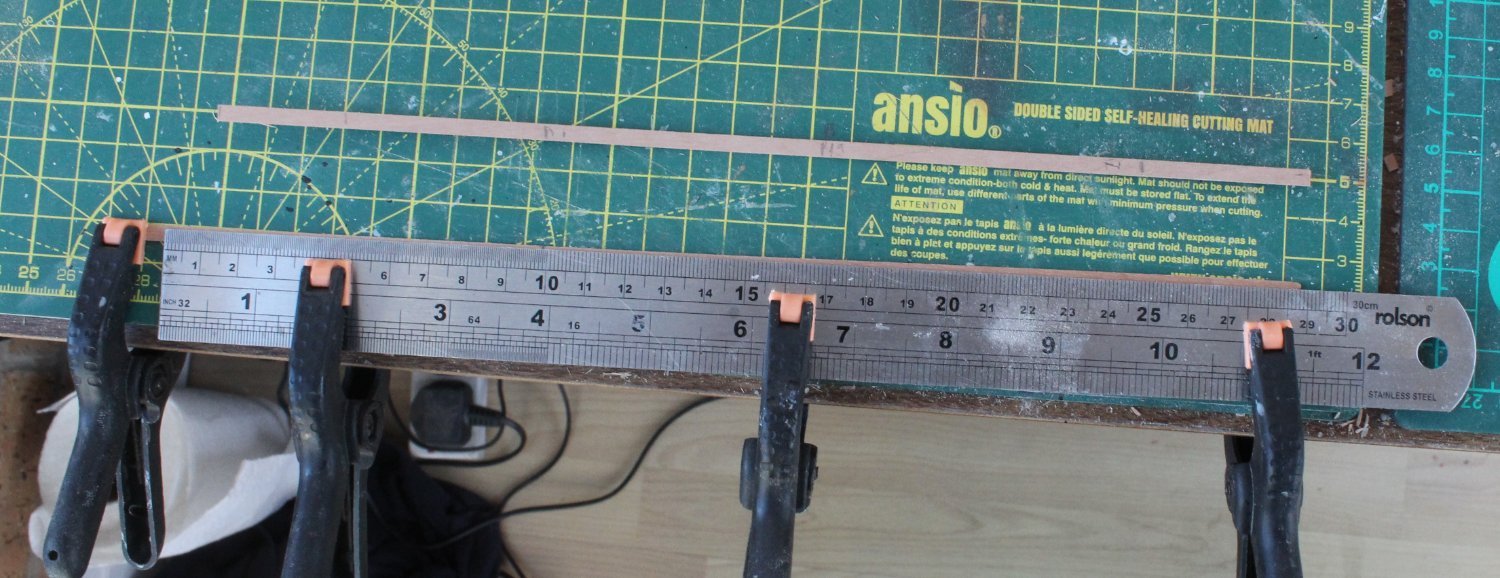
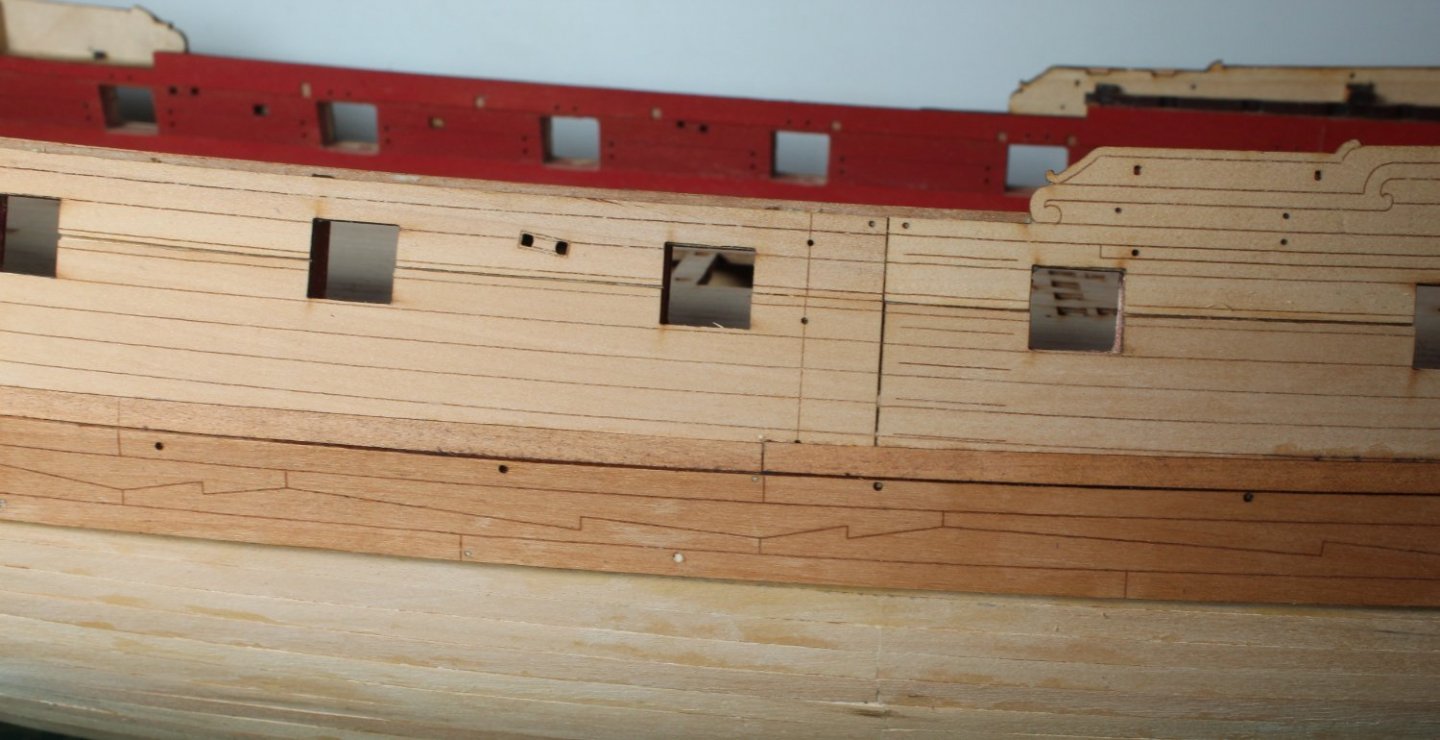
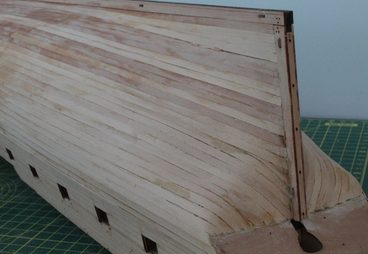
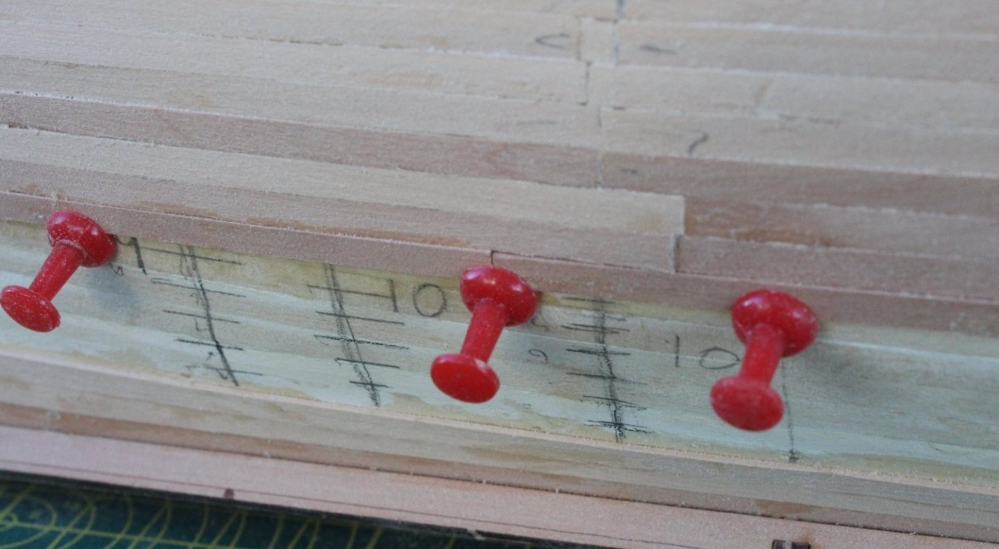
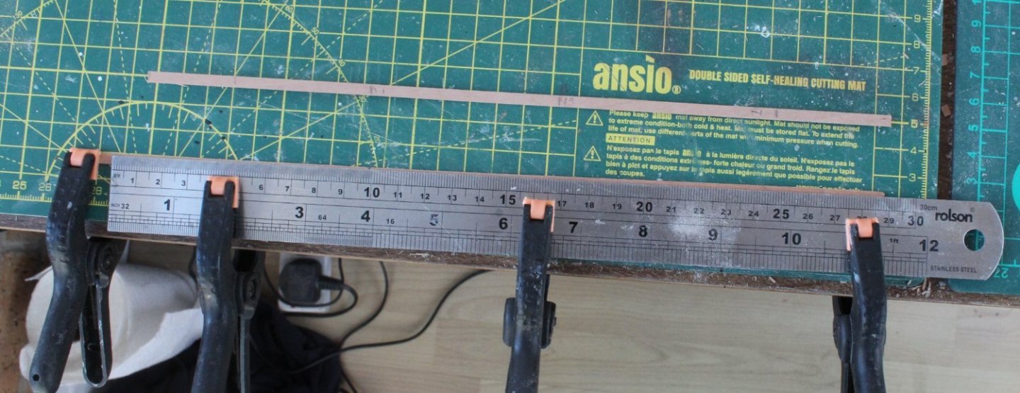
I am still making slow and steady progress with the second planking. As per my previous posts I am using Titebond Original to glue the planks to the hull which are then held in place with map pins. I have been working top to bottom, however I have also fitted three planks to the keel (garboard). Close up of bow area. The stern is looking much better than first feared after a very light sand but this area will still require a lot more work. I have made a series of measurements regarding the number of planks require to fill the gap at various points. At the widest point requires 10 planks and at the bow it require 6 planks to fill the unplanked area. 6 planks x 4mm = 24mm therefore each plank needs to be 2.4mm wide at the bow. I made a template plank which shows the require plank widths at different points which can be transferred to each plank in turn. I have found it beneficial to clamp the ruler (which provides the straight edge cutting line) on top of the plank to be cut.

- 476 replies
-
- 9
-
-
- sphinx
- vanguard models
- (and 1 more)