Glenn-UK
-
Posts
3,172 -
Joined
-
Last visited
Content Type
Profiles
Forums
Gallery
Events
Everything posted by Glenn-UK
-
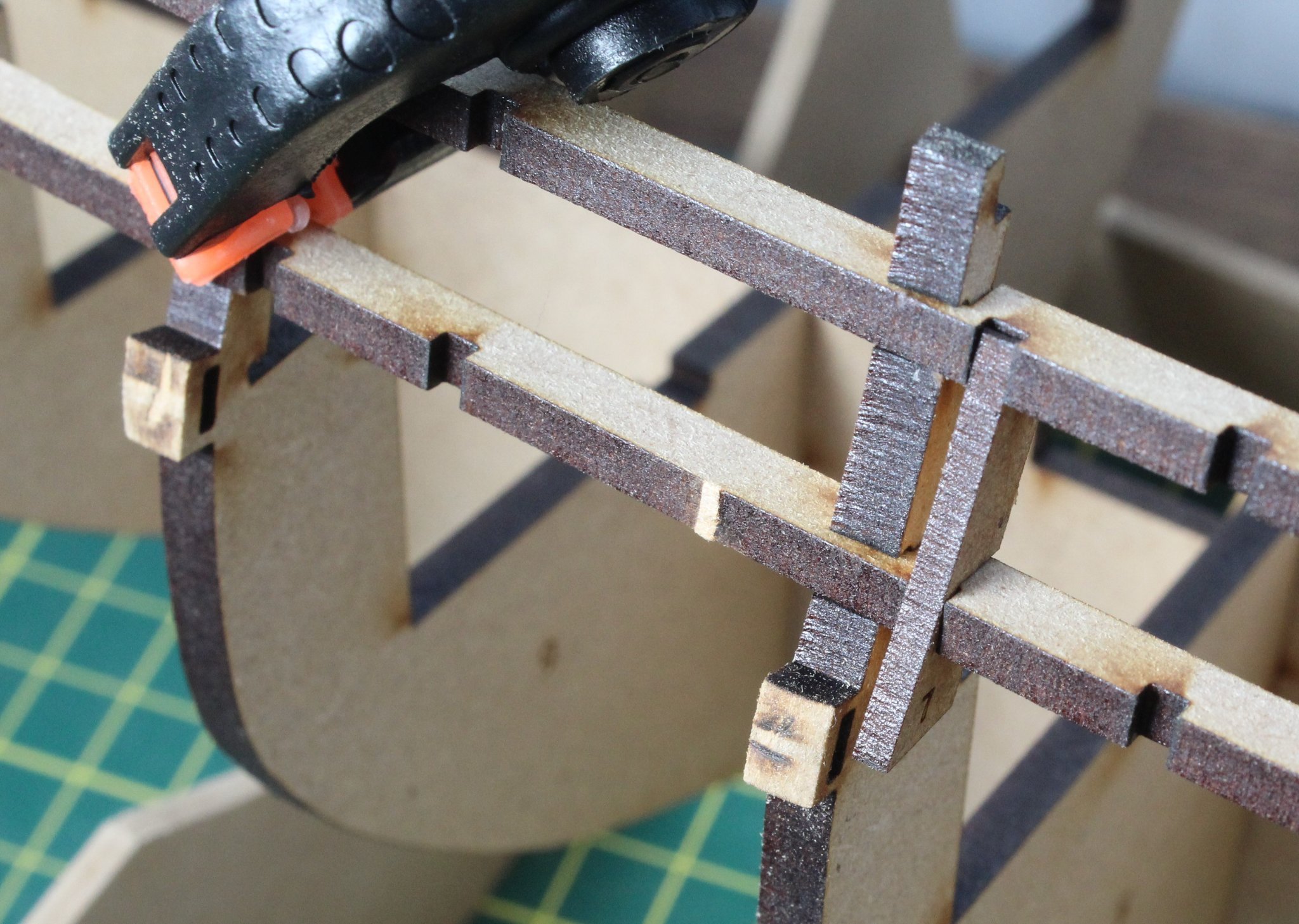
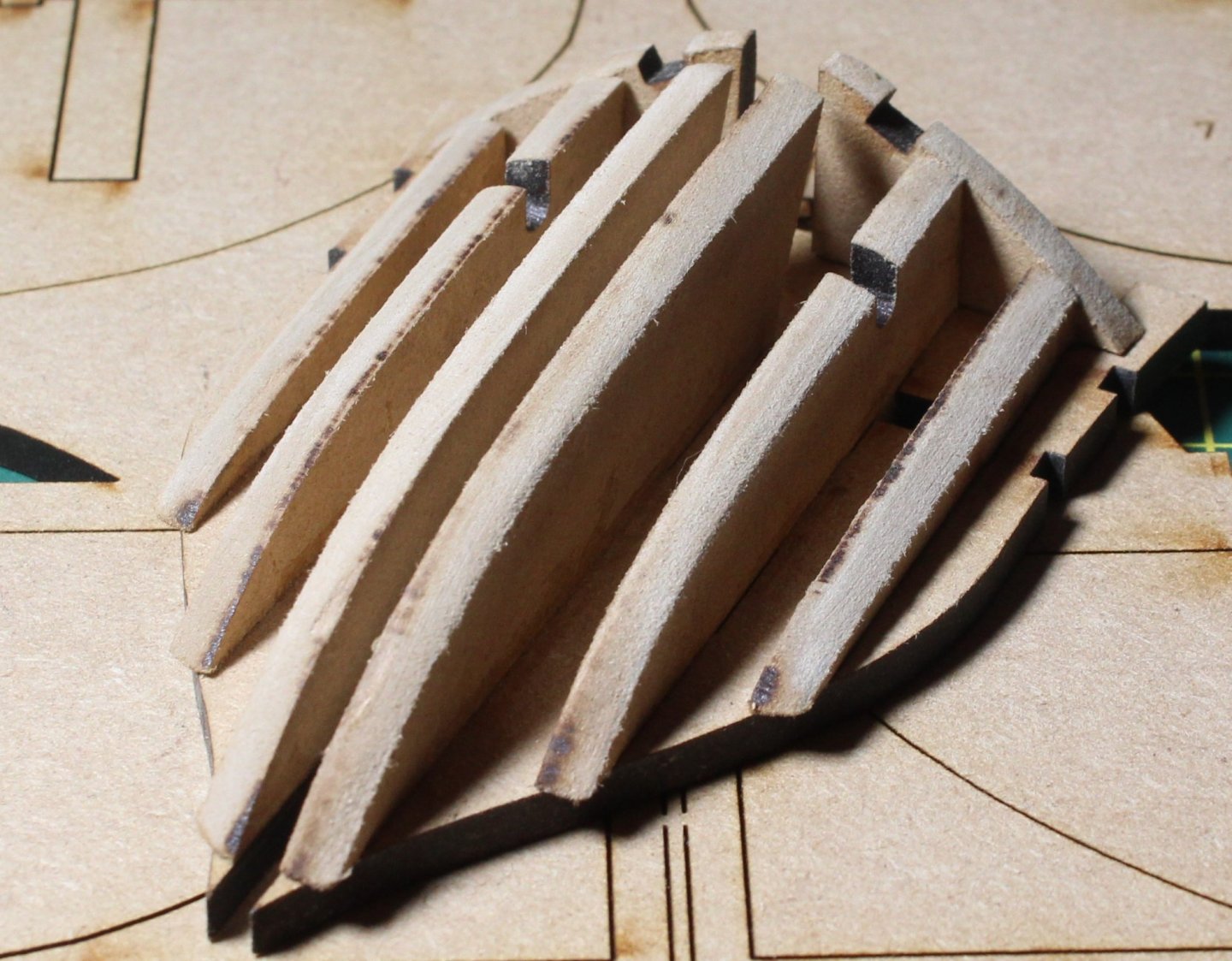
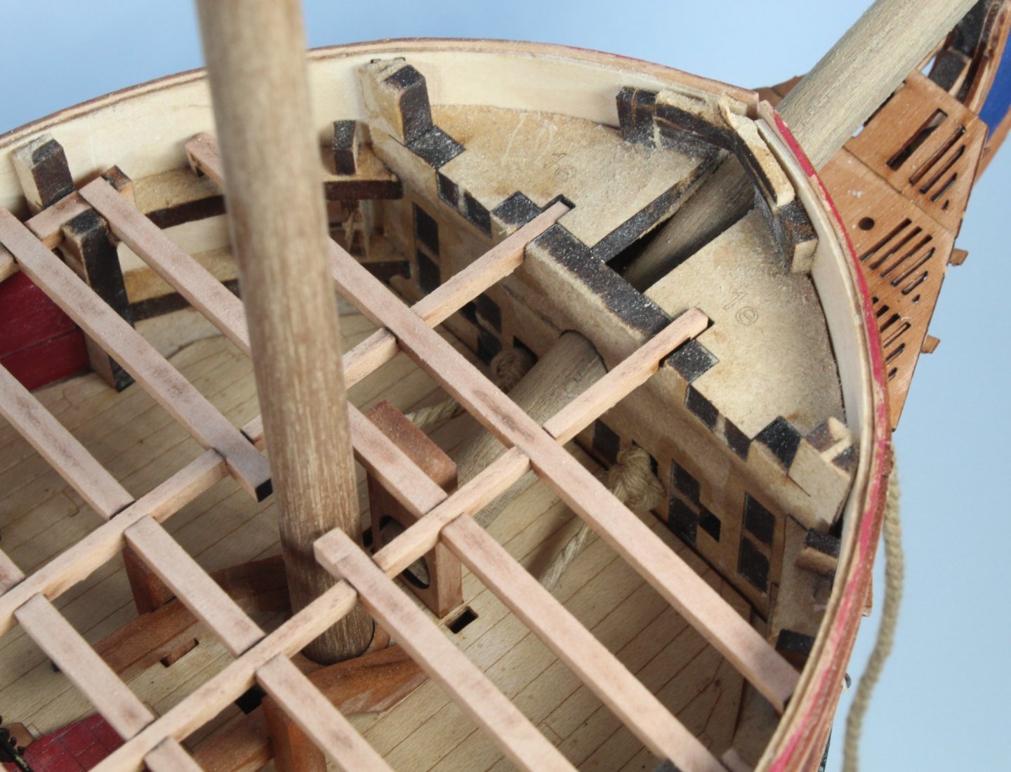
 With a little bit more of dry fit experimentation the penny finally dropped why the horizontal gun port patterns sit flush with the bulkhead at the bottom and are not sit flush at the top of the bulkhead. The bulkhead area where these patterns are located is curved which explains why this is the case. I may experiment with filing some angles on the horizontal gun port patterns slots, using one of the spare parts I have, to get the part to sit flush which should then simplify the sanding process to remove laser char prior to fitting the outer bulwark patterns. I also need to check how this assembly looks with regards to the fitting of the inner bulwarks as the inner surfaces also need to be flush again with the removal of laser char. The smaller vertical gun port patterns are curved to match the bulkheads and tend to be flush fitting with the horizontal gun part pattern, with the exception of the bottom edges in some places. This photo, taken at gun port 7 / bulkhead 8 provides a nice illustration of how the parts look when fitted I certainly did not take enough care with the V1 build to check how these parts will look when properly fitted which resulted in me not fitting them properly. This error on my V1 build was then probably the starting point of the subsequent alignment issues I had. I am really pleased I have already taken on aboard some lessons learnt from the V1 build such as: a) Trying to understanding the design processes better and how the parts should look when correctly fitted, such as detailed in this post b) To take much more time and care with each build stage, I am in no rush this time around to glue parts together c) To look ahead at the different build build stages, drying fitting as much as I can I also plan to check the fitting of the following items before I actual start the assembly process in earnest, noting I will have to remove the bulkhead 13 infill piece to do so: a) Quarterdeck beam spacing patterns b) Stern counter frames (inner, middle and outer) as I seem to recall these were a very tight fit with my V1 build c) Stern frame spacer beam This photo is an example of dry fitting multiple parts to get an idea of how things should look. Since taking this photo I did dry fitted many more vertical gun port patterns.
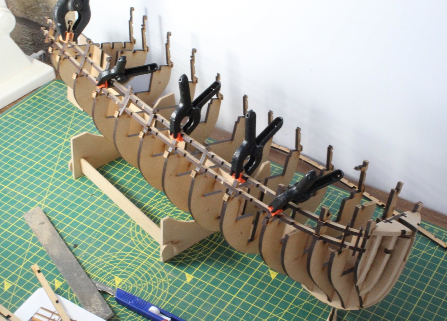

- 476 replies
-
- 11
-

-
- sphinx
- vanguard models
- (and 1 more)
-
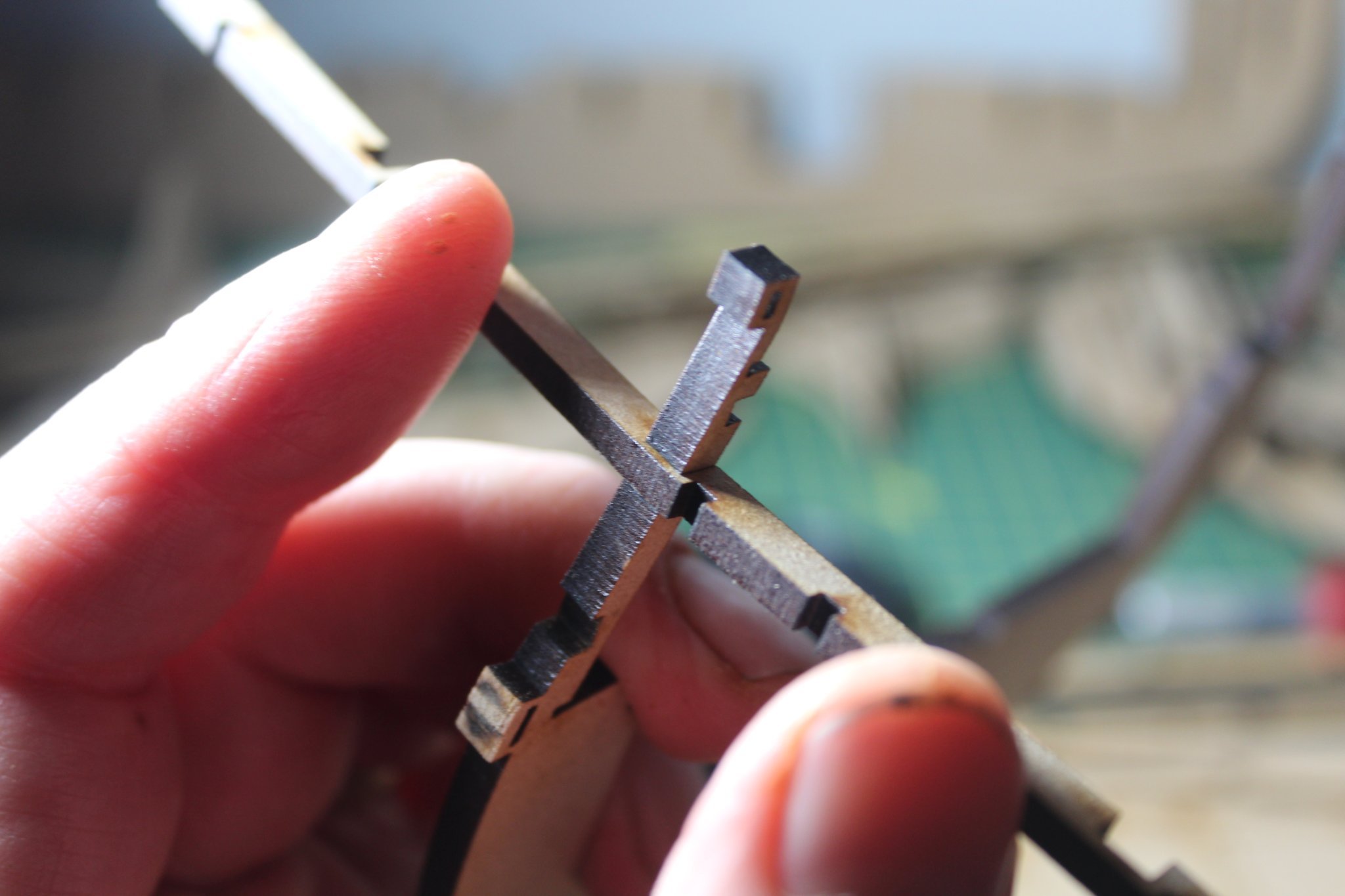
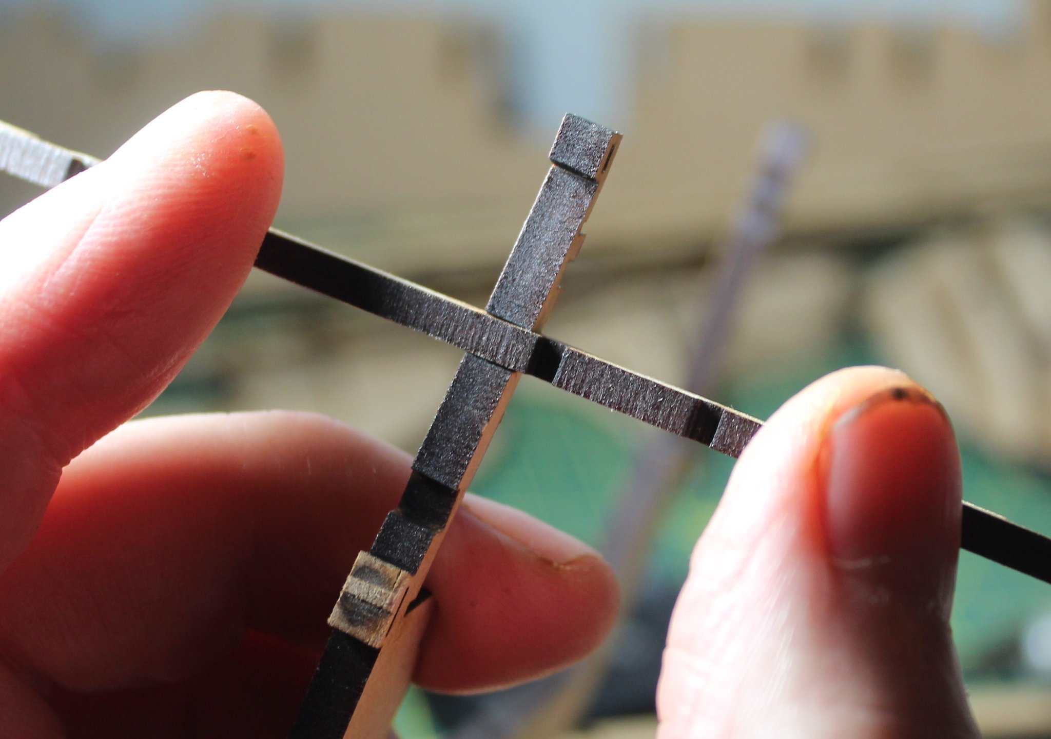
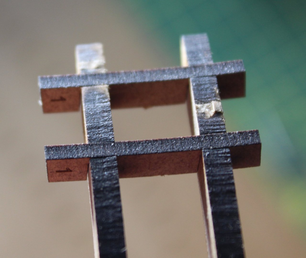
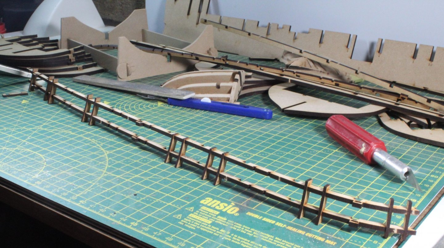
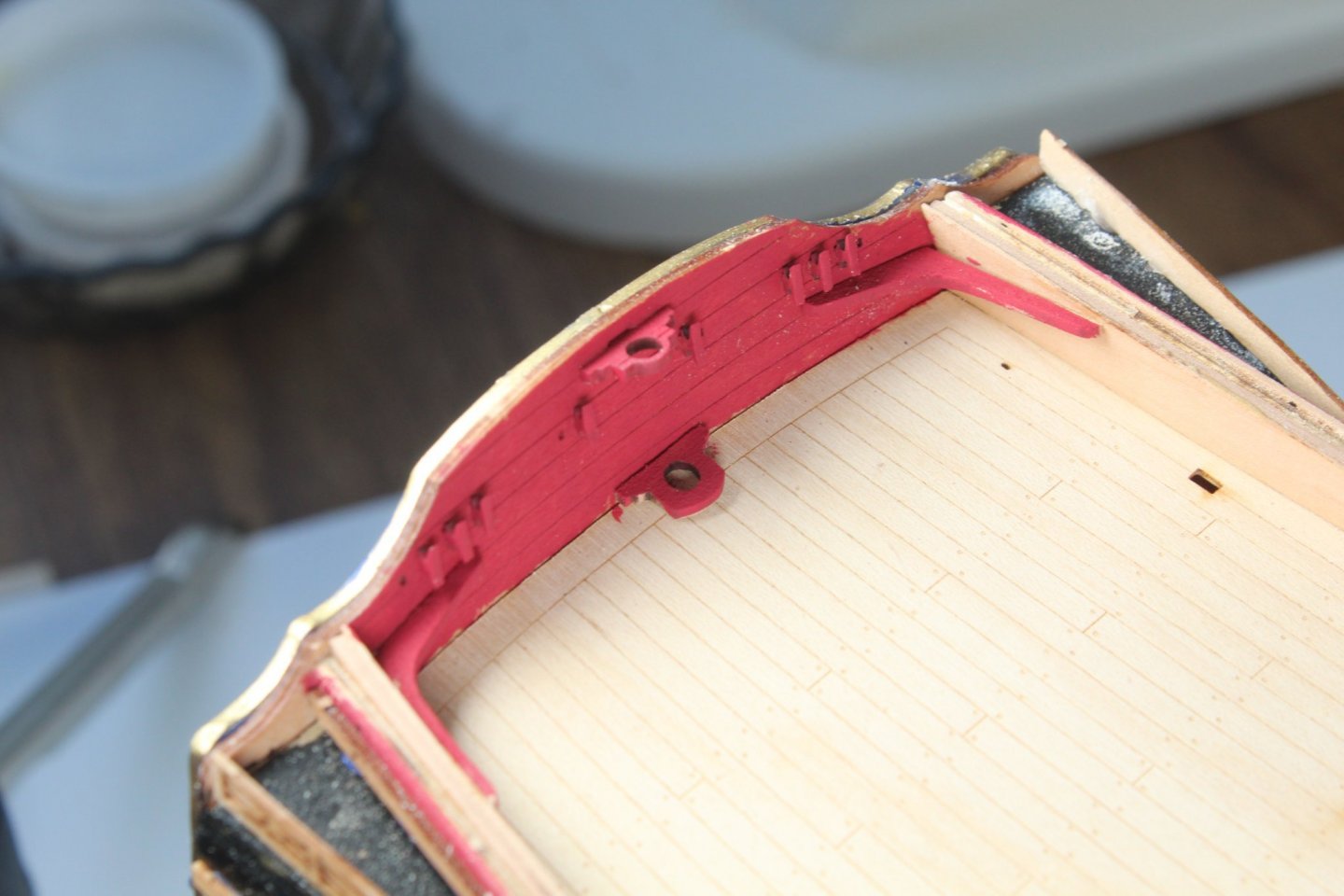
When I bought the V2 kit I also order some spare sheets so I could try some experimentation and not to worry too much if I damaged the parts. I am also also trying to take much more time and care this time around. I started with the assembly of the stern bulkheads (13 and 13-1). I am still unsure how much I need to fair this assembly, with respect to the edge between bulkheads 13 and 13-1, so any advice greatly appreciated, I have the spares available so I can redo this assembly if required. I will leave as is for the time being and will fair further prior to the planking phase if necessary once I have tried laying some planks to check how they flow across the bulkheads. I have also built and faired the bulkhead 1 assembly. Again it may require additional fairing before the planking phase, and I do have spares available if I need to revisit this. One of the concerns I had with the V1 kit was how proud the vertical and horizontal patterns were from the outer edge of the bulkheads which then required a great deal of sanding. With that in mind I have been test fitting the various parts and in general my initial tests would indicate the bottom edge of the horizontal gun port patterns is flush with the outer edge of the bulkhead but sits 1 to 2mm proud at the top edge, see photos below. I still need to do a few checks, one being with the bulkheads dry fitted to the keel and to then dry fit the pattern. I have already realised I did not fit these patterns correctly on my V1 build. The excess material can be seen at the top Moving on to the vertical gun port patterns, when fitted correctly there seem to be a really good fit. The first thing to note is there is a right and wrong way to fit each gun port. When fitted correctly they are flush with the vertical gun port patterns. A messy work station, as I currently releasing the various parts from the MDF sheets and shows the vertical and horizontal gun port patterns test fit.


- 476 replies
-
- 8
-
-
- sphinx
- vanguard models
- (and 1 more)
-
That is true, I'm hoping to have learnt from some of my mistakes and not to repeat them on the V2 build
-
Many thanks
-
Many thanks Bob
-
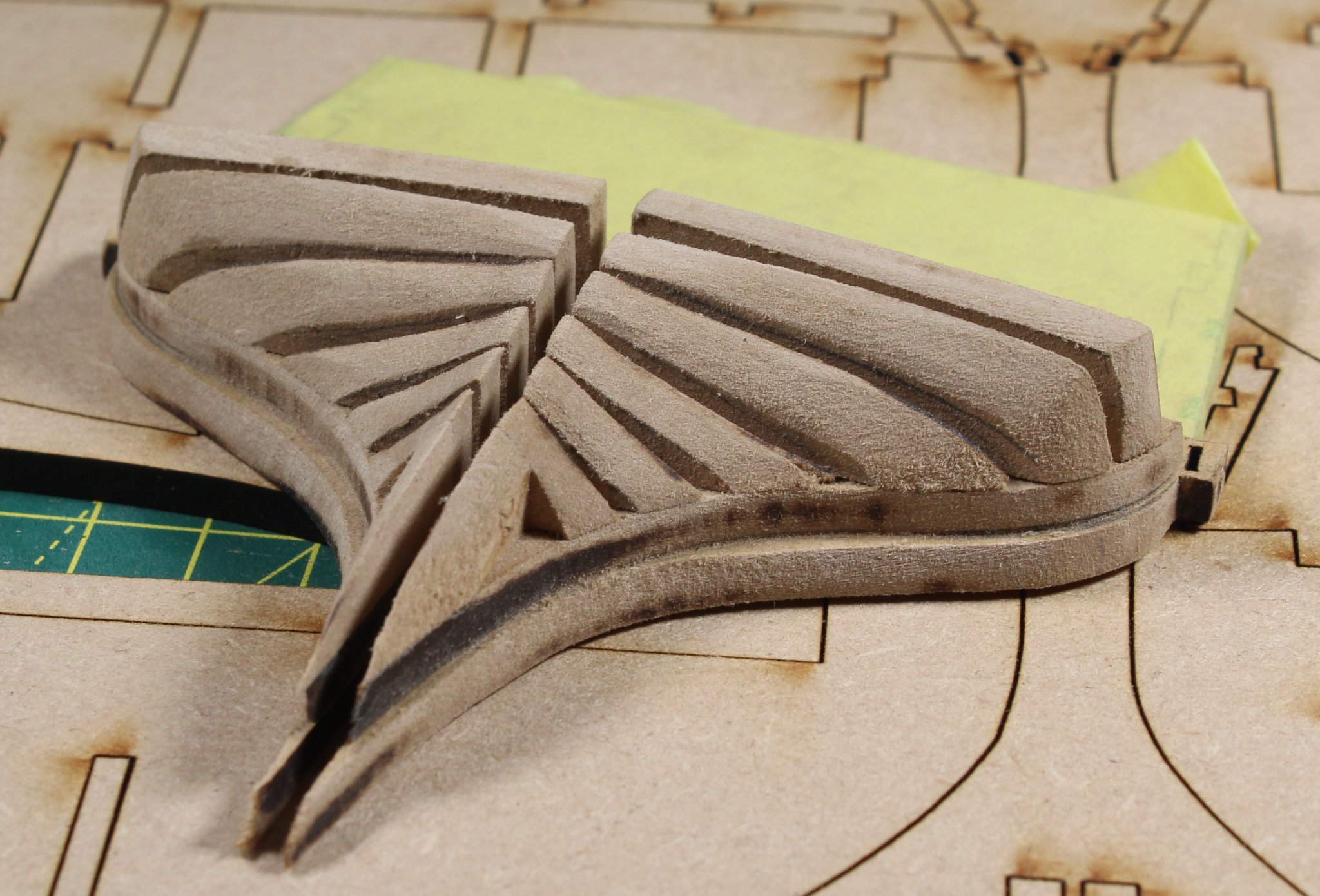
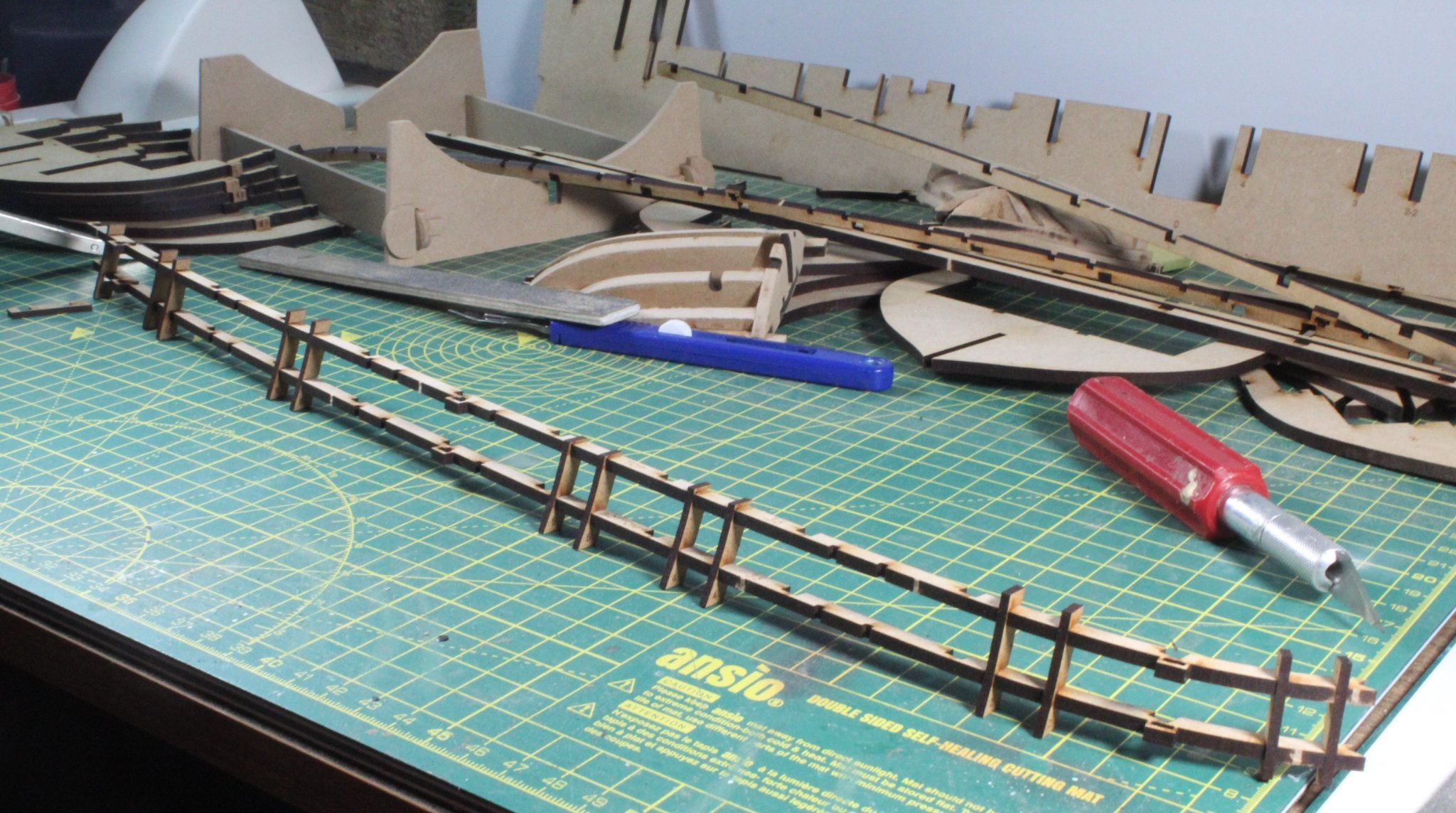
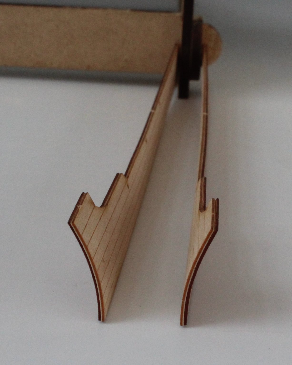
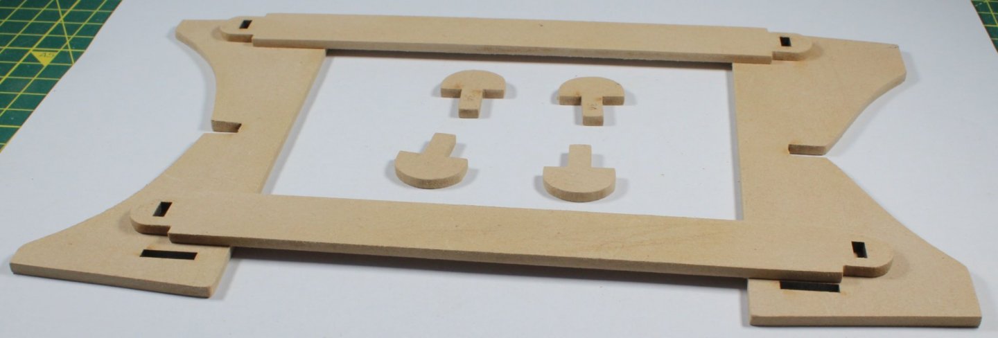
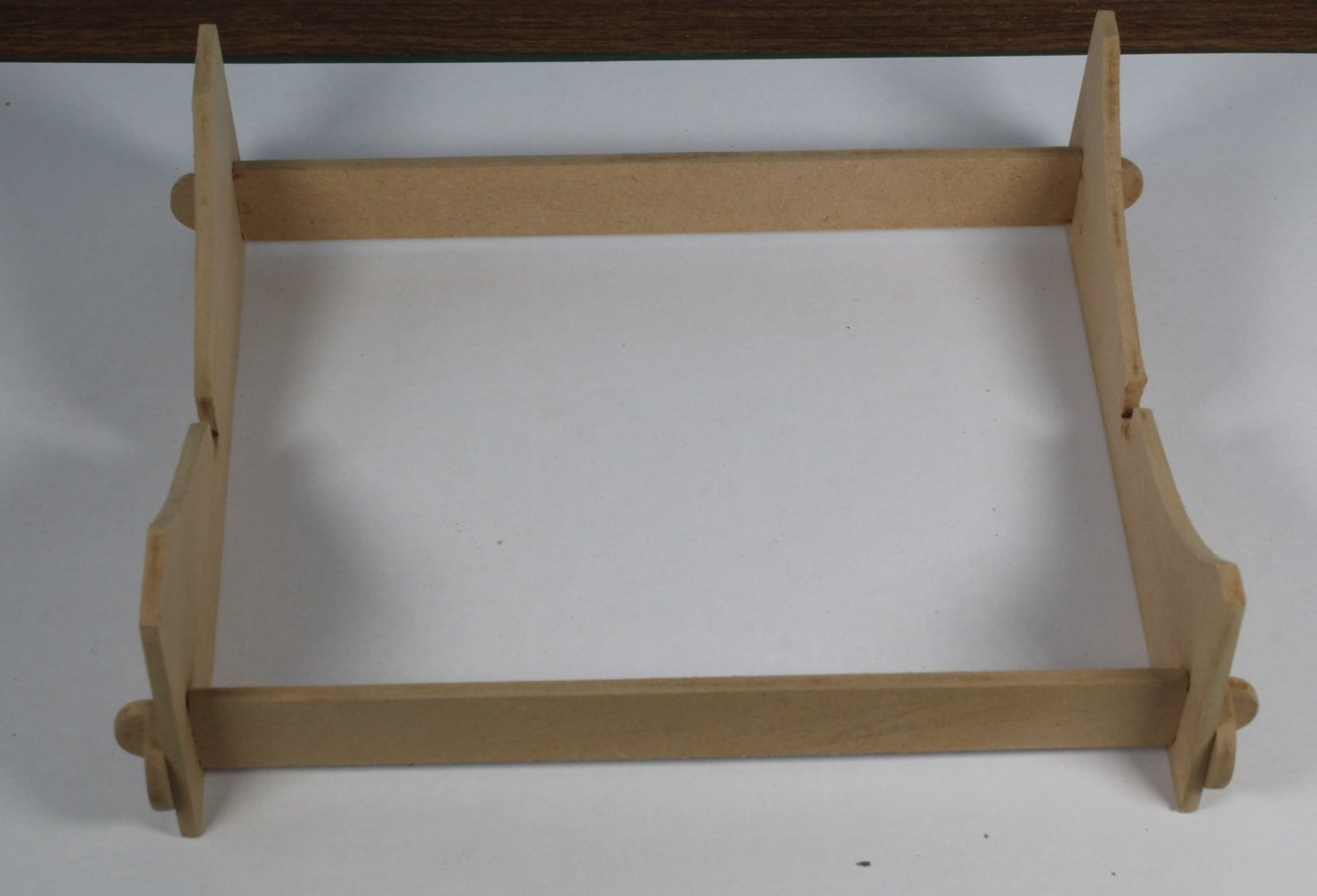
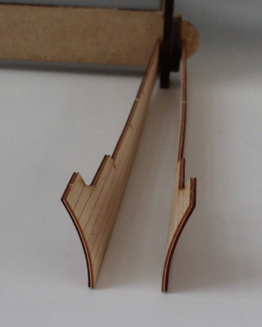
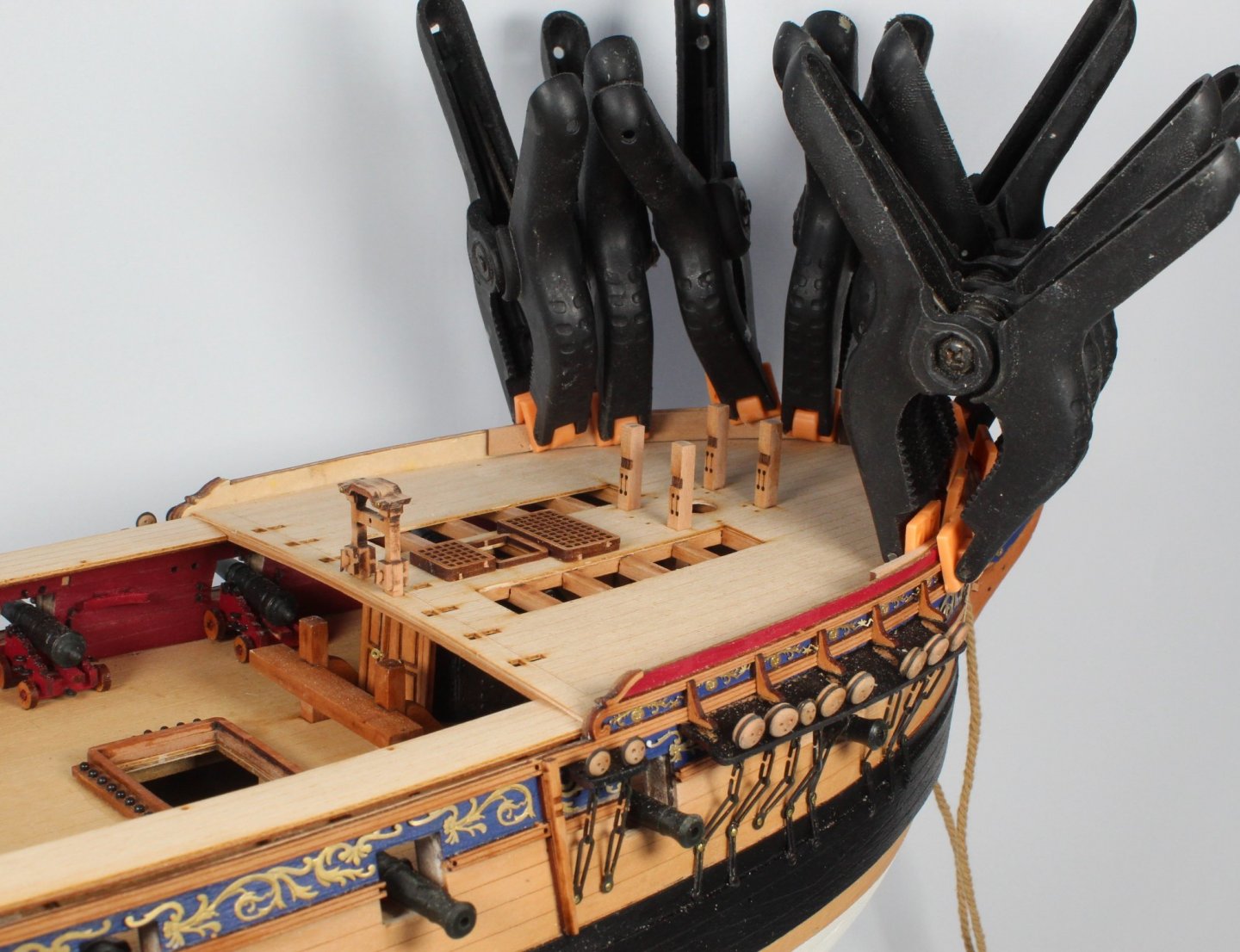
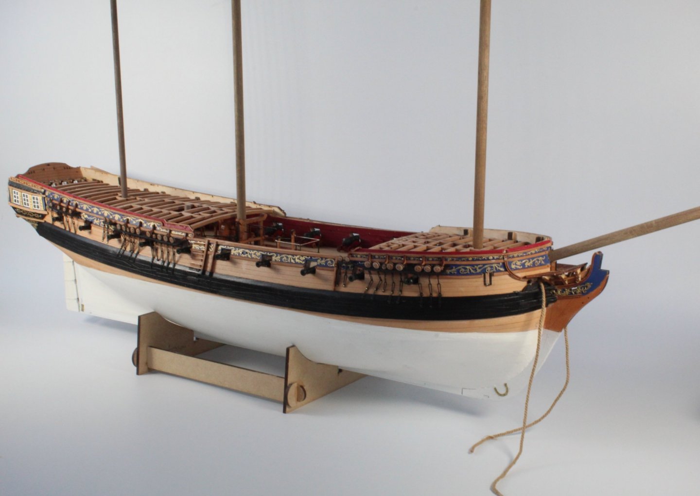
I have reached the stage with the V1 HMS Sphinx build where I am happy to stop work, a picture of the V1 build is shown below The shipyard has now been tidied to make sure everything is ready for the V2 build With @Chuck words regarding laser char still ringing in my ears I feel duty bound to ensure I removed the laser char from all the parts with this build. Starting with the cradle, which will be become redundant later on in the build process I used a technique suggested by @James H to remove the laser char from the angles. The method is to wrap sandpaper around a small steel ruler and to use the thin edge to remove the char. It worked very well. I used a combination of sandpaper and standing sticks to remove the laser char from all the other edges. This photo shows all the cradle parts with the laser char removed and ready for assembly The cradle has now been assembled but I have not added any glue as I am planning to try some painting techniques. The completed cradle will be painted black. Therefore I need to disassemble the cradle so each part can be painted individually when the material I have ordered arrives in the next day or two. I am aware there is some remnants of laser char on the top edge of the right hand end piece which will be removed before I start the painting phase.

- 476 replies
-
- 9
-
-
- sphinx
- vanguard models
- (and 1 more)
-
That is the plan, slow and steady.
-
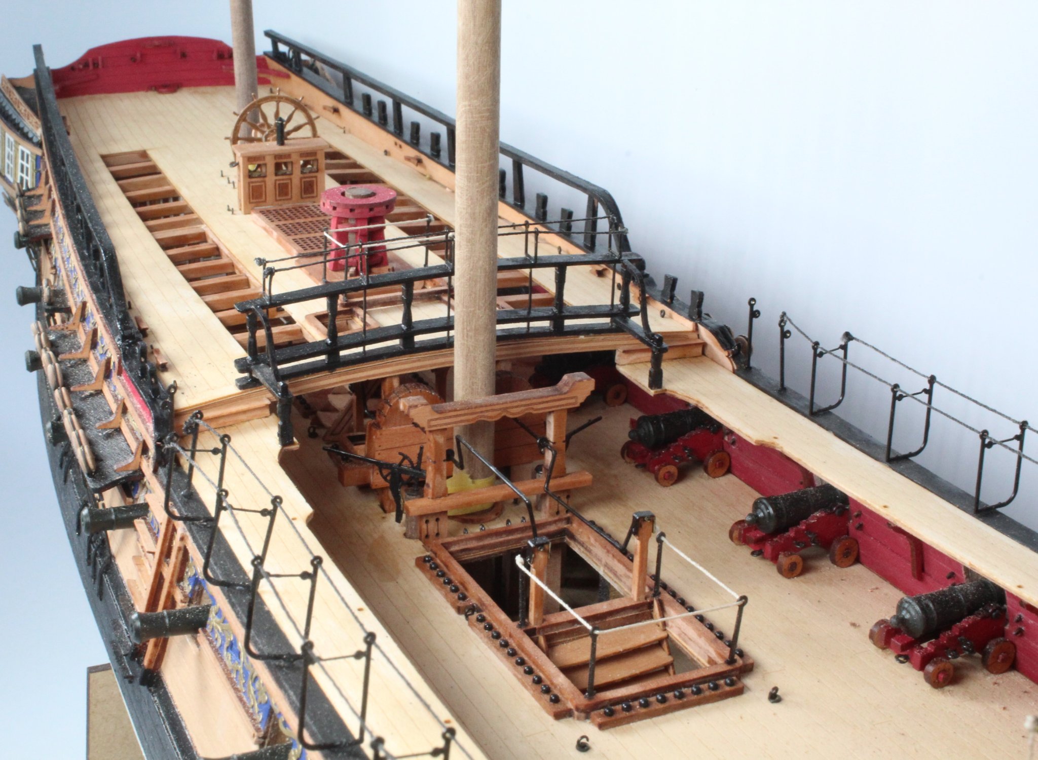
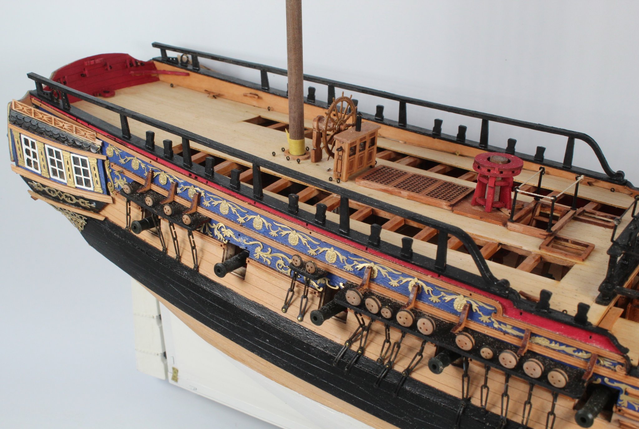
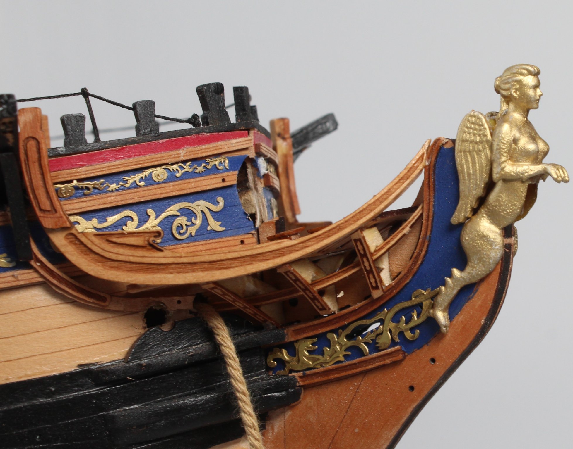
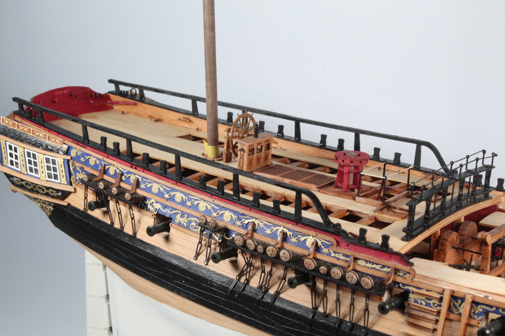
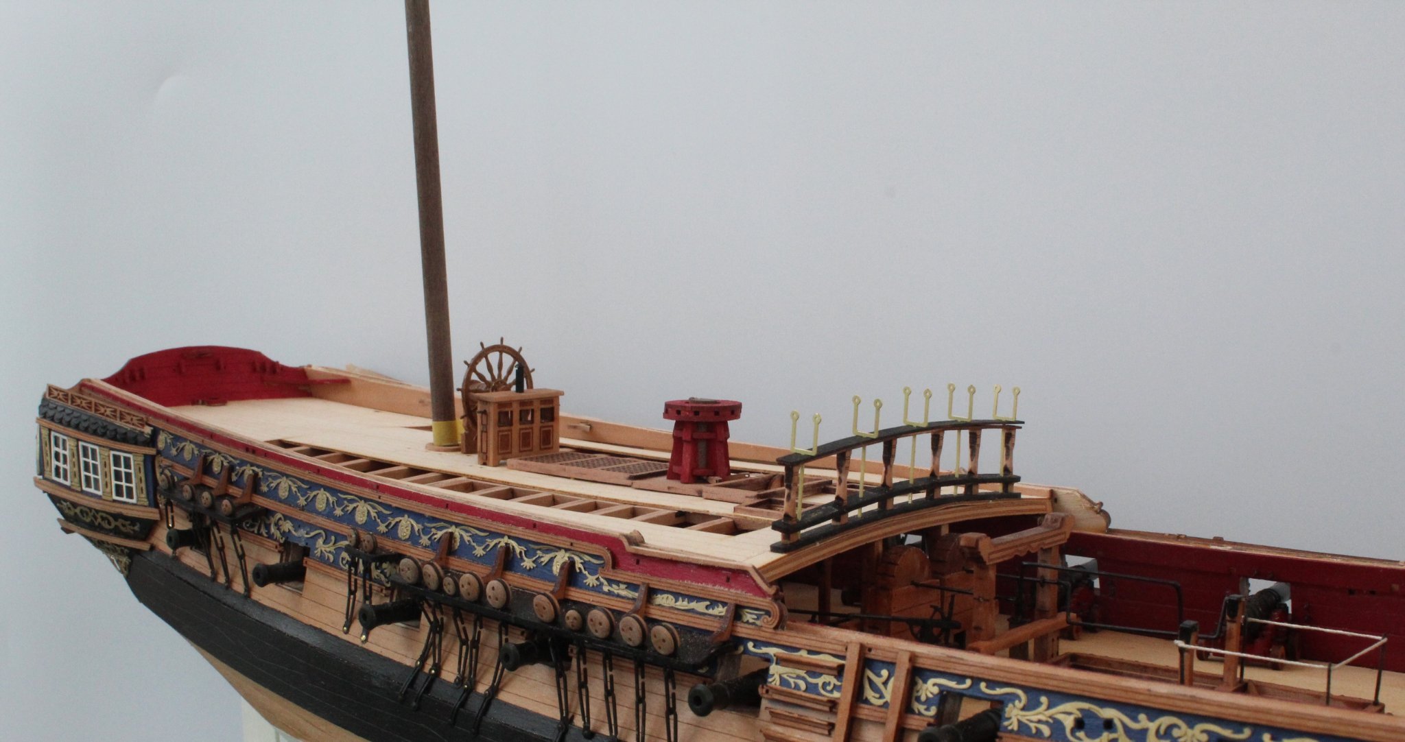
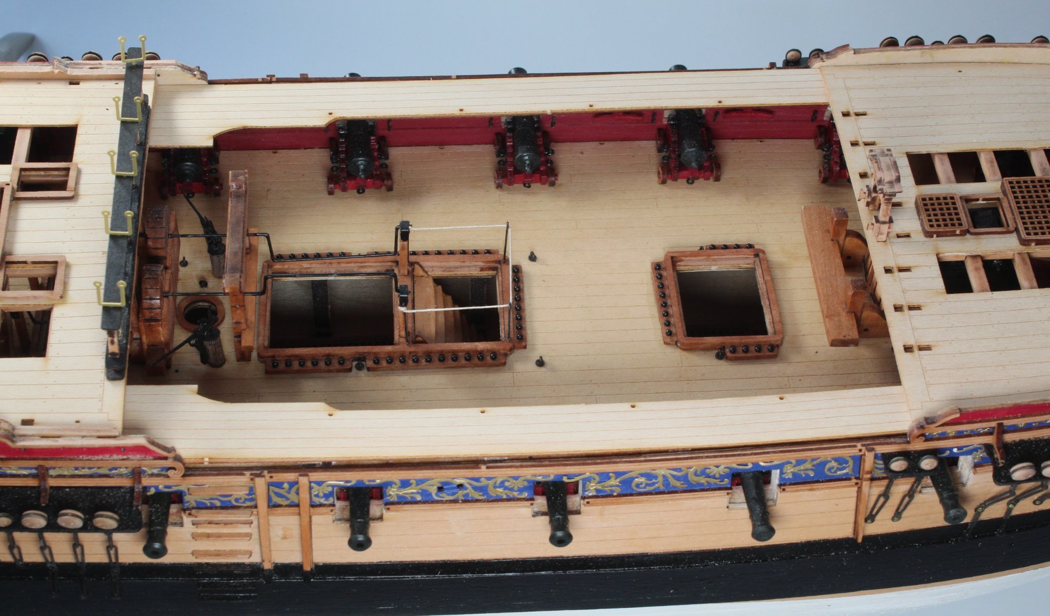
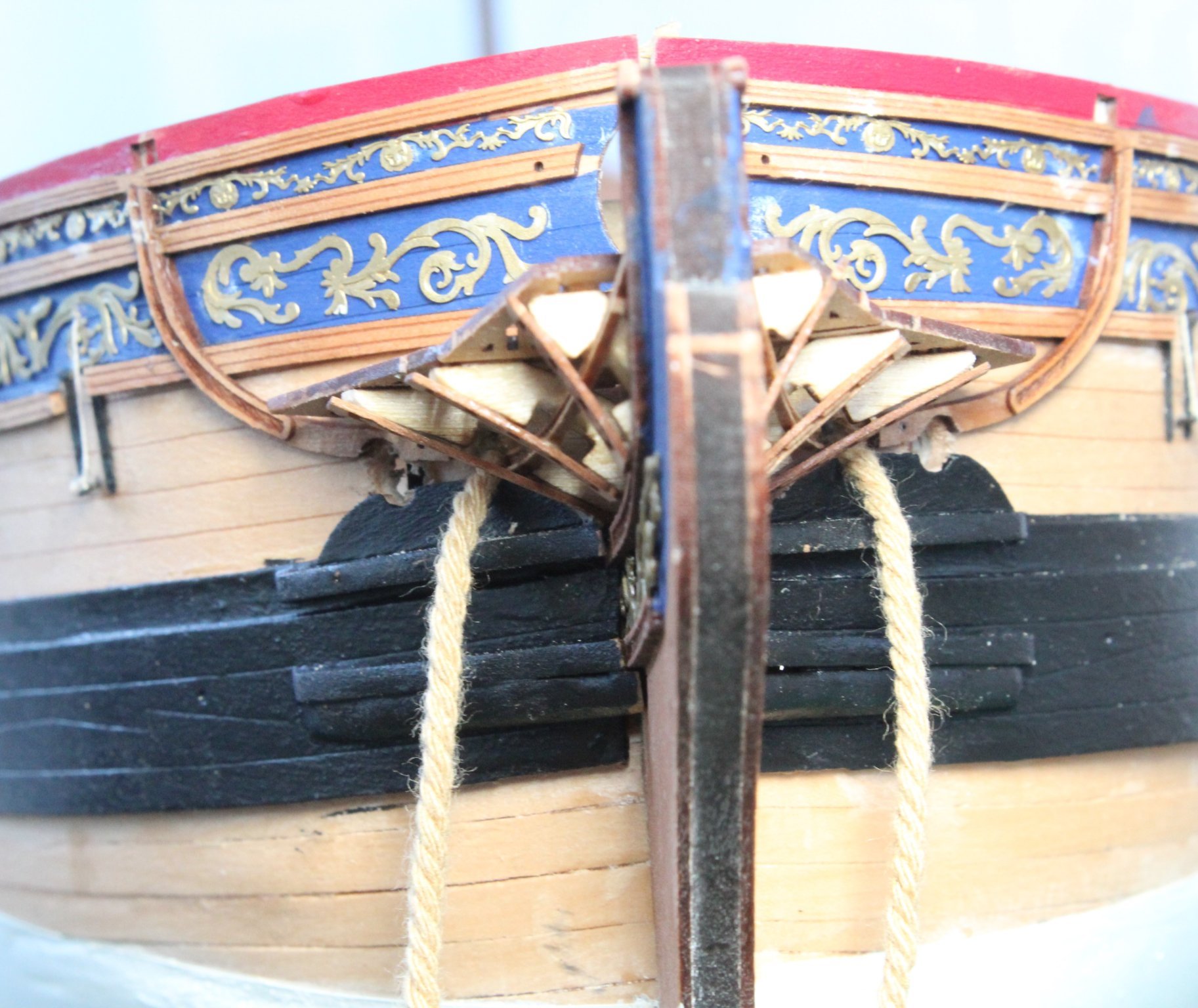
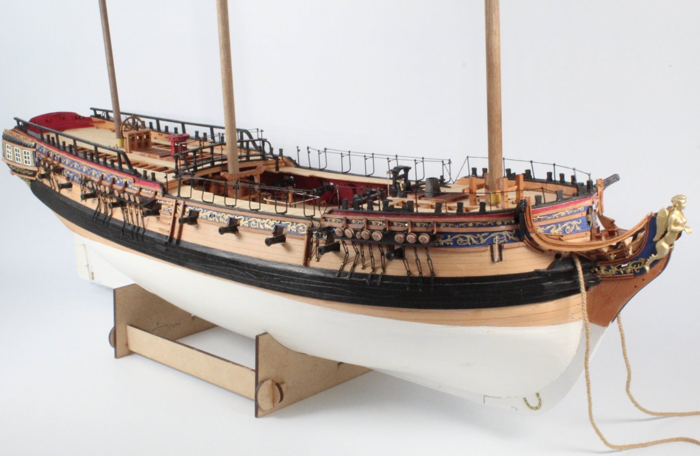
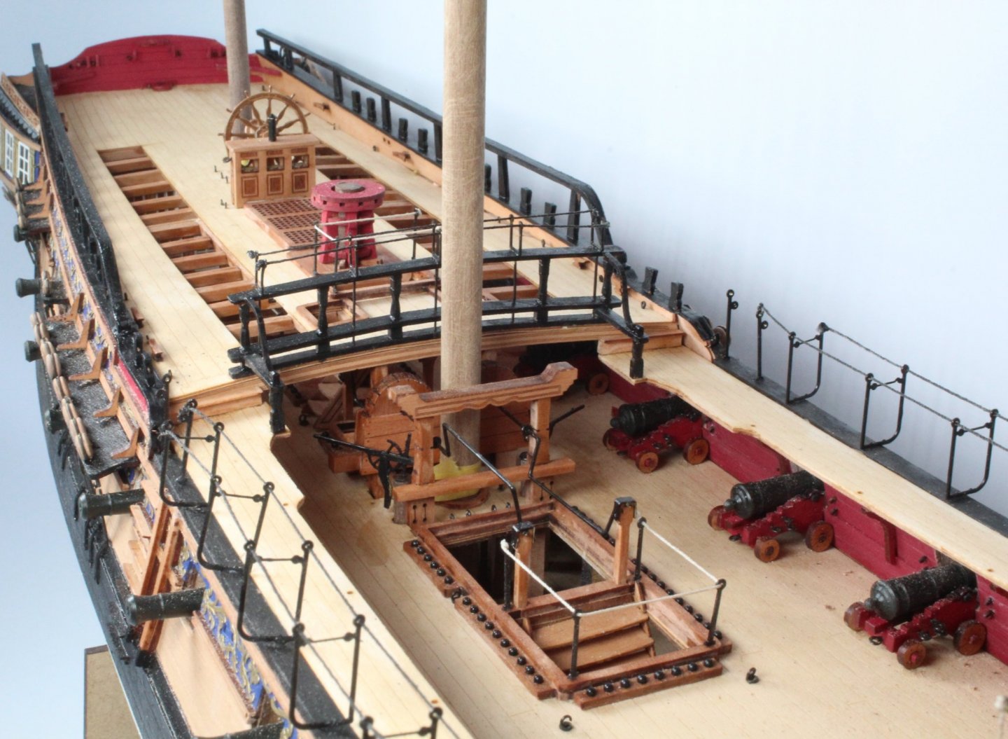
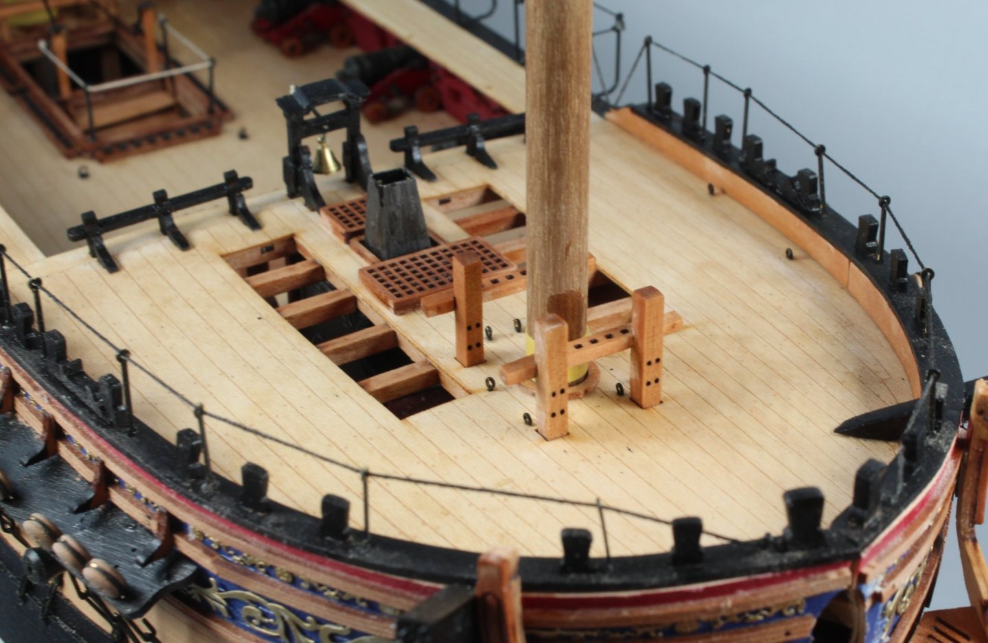
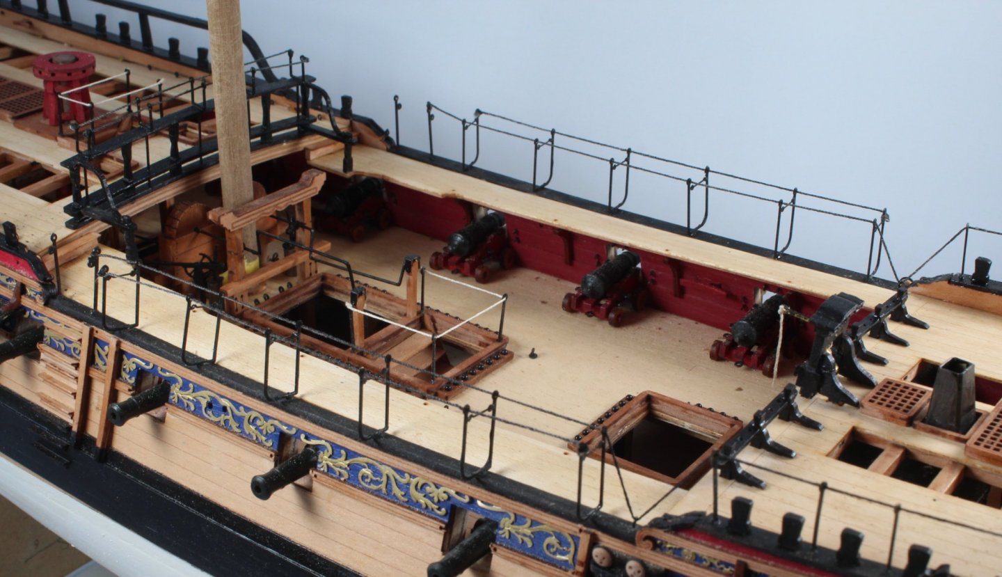
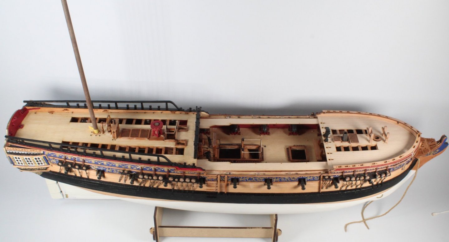
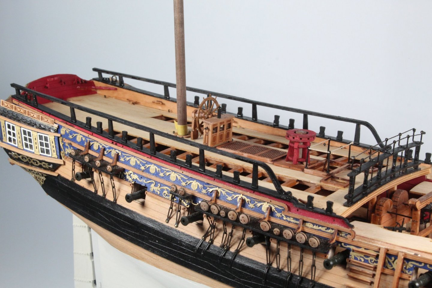
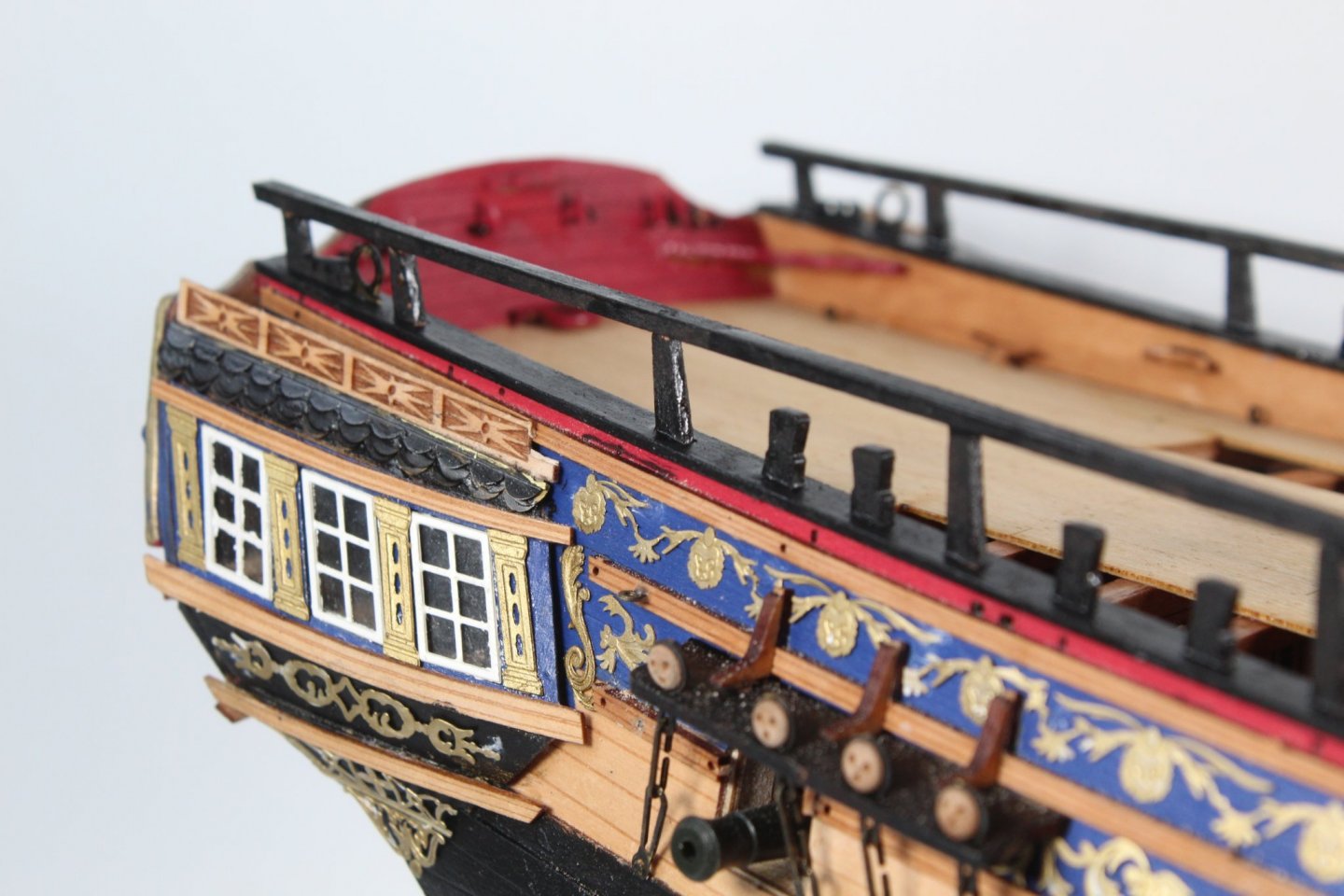
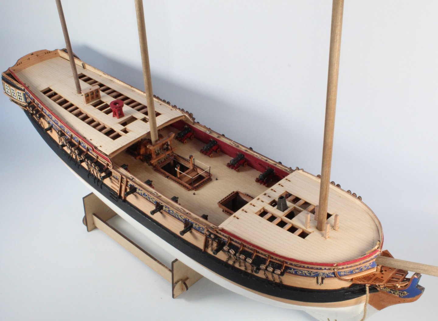
I have finally reached the stage where I will stop work on the V1 build and move on to starting work on the V2 build. I have really enjoyed the V1 build. I am currently undecided if I will progress the build further at a later date. My current thinking is probably not and keep it as a hull only build. The first picture is the current state of play with the V1 HMS Sphinx. The right-hand gangway hammock cranes are a bit wonky as the gunwale has a slight inboard lean . The plan sheets show hammock cranes for the stern area, but I noted there where not fitted in the prototype build so I opted to omit them from this build. I also decided not to fit the gun port lids. Given the mistakes I have made during this build process the end result (so far) does not look anywhere near as bad as I first feared it would. This proves, without doubt, what a great design this kit is when a ham-fisted error prone builder like me can produce a reasonably nice looking model. A big thanks to @chris watton and to @James H for the all the work they have done. vanguard Models continue to design and release amazing kits and to my mind are the best kits on the market. This is a picture of the figurehead. The resin part was primed and then painted gold before the installation. The bow main rail assembly has also been fitted. I did like the description of the heads in the build manual as "seats of comfort", the tops of which are just visible. This shows the forecastle with everything fitted. I think I overdid the weathering of the stove chimney. The gangway walkways caused me more problems than I was expecting. Initially with the curling issue and then I totally misunderstood where the gangways were to be fitted in relation to the gunwales, but once the penny dropped it all made perfect sense. I have also added the step and rail up to the quarterdeck A close up of the step and rail To finish off this post I have added a couple of pictures of the quarterdeck


-
I am planning to start work on the v2 kit in the next day or two so exciting times ahead
-
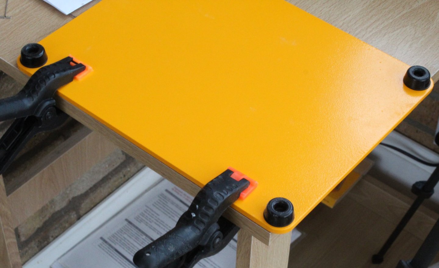
The parts started to curl as soon as the wood glue was applied. I think they need to be clamped flat before the glue cures. Fingers crossed they will be be flat in the morning
-
I have come across some very informative videos on YouTube which have been posted by Olha Batchvarov who is a professional model boat builder. The first video covers the first planking - First Planking Video There is a nice section where a drop planks are added. There is also a video which shows the sanding process afterward - Sanding The Hull This video also covers fitted the stem and stern posts There are several more videos on her YouTube channel
-
When I glued the gangway deck patterns to the waist gangway patterns I have the same problem as with the gallery cabin bulkheads. The photo below shows the problem, in that the glued parts have curled. The parts were well clamped after the glue was applied so I need to think about the best method to do this on the V2 build to avoid the curling issue. The parts have been soaked in water and clamped flat. I will leave the parts clamped like this overnight and hopefully this will resolved the curling issue as the parts cannot be fitted with a curl as they do not sit on the supporting knees. In the meantime I have done a bit more work on the forecastle. The gunwales and catheads have now been fitted. I have also fitted the Forecastle Rail assemblies and ships bell. Looking at the photo below there is a gap between the deck and righthand side inner bulwark by the bowsprit. I did not notice this when the part was fitted, must do better on the V2 build. The fitting of the catheads took quite a bit of work and I need to think how I will do this better on the V2 kit. I just need to fit the deck hammock cranes, eyebolts, belaying pins and timber heads.

-
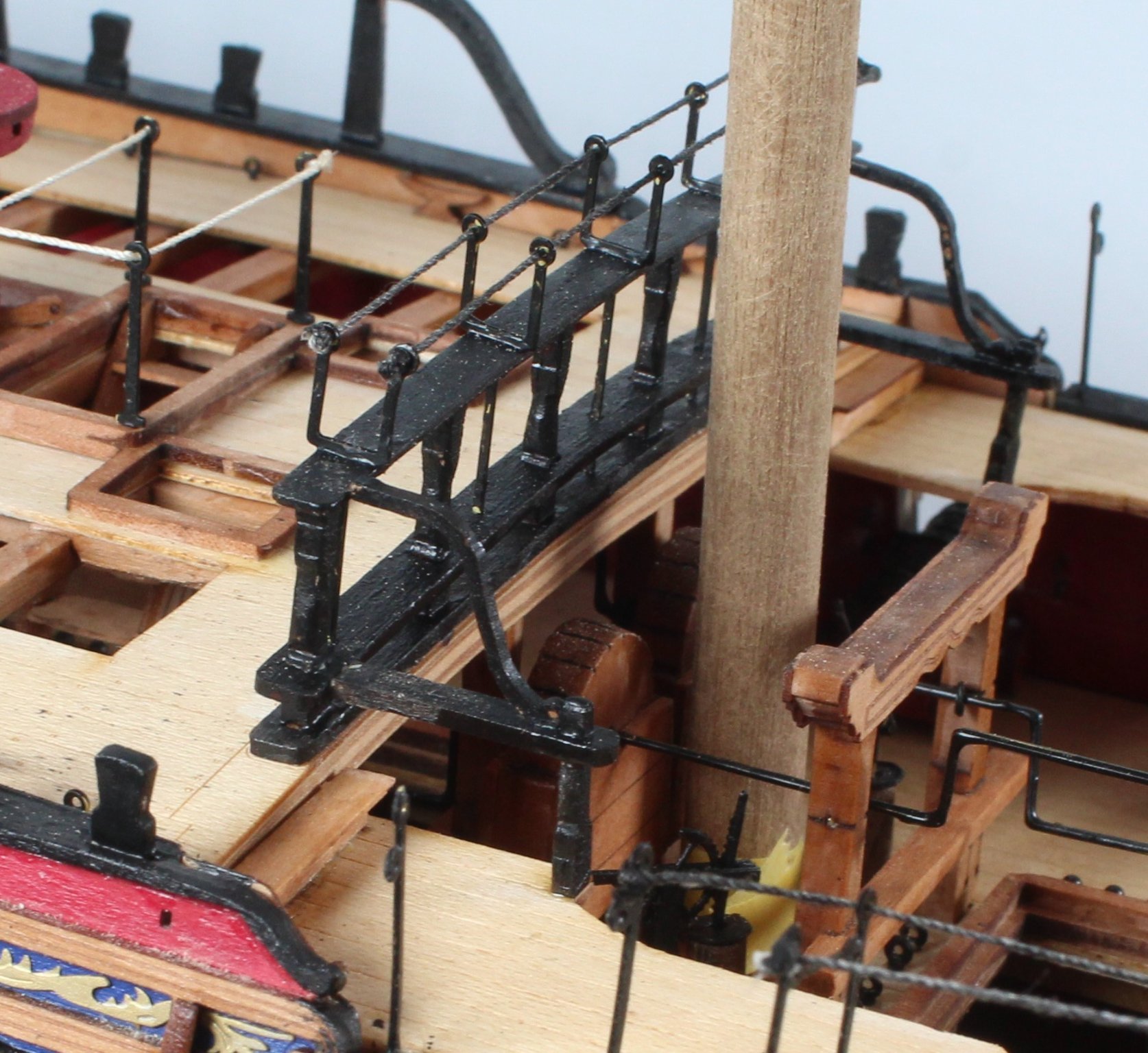
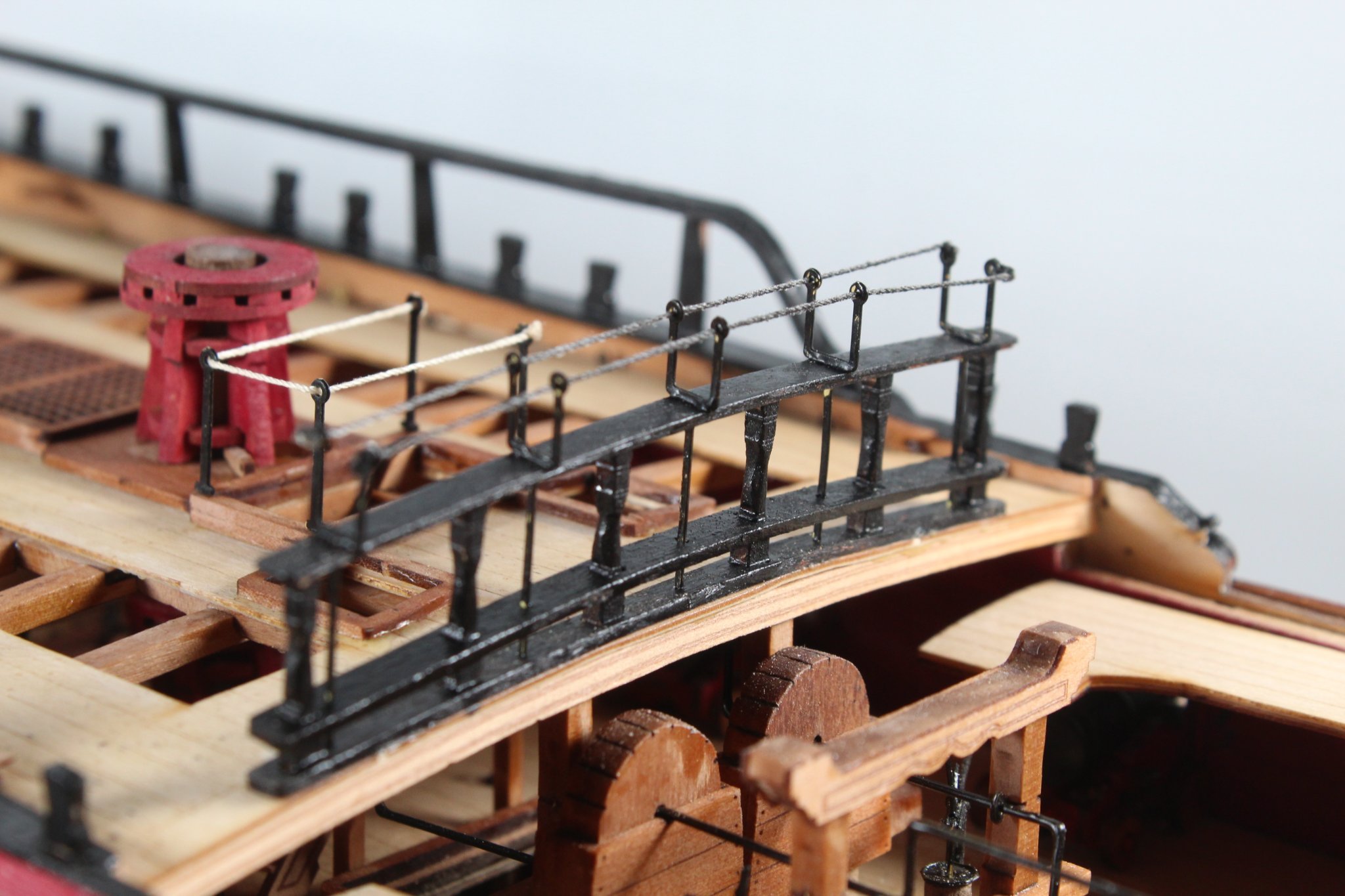
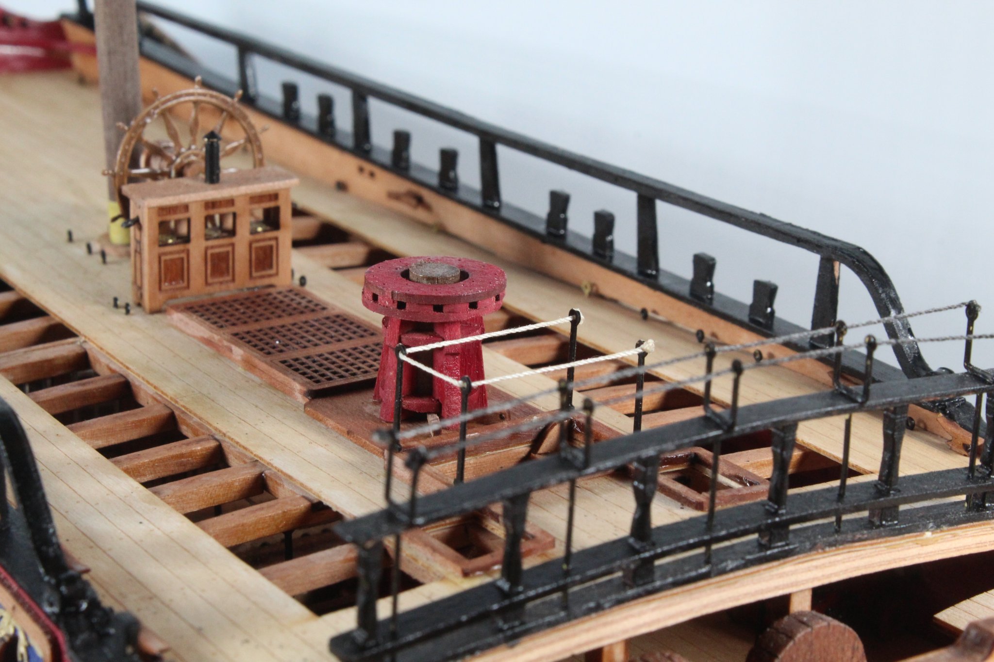
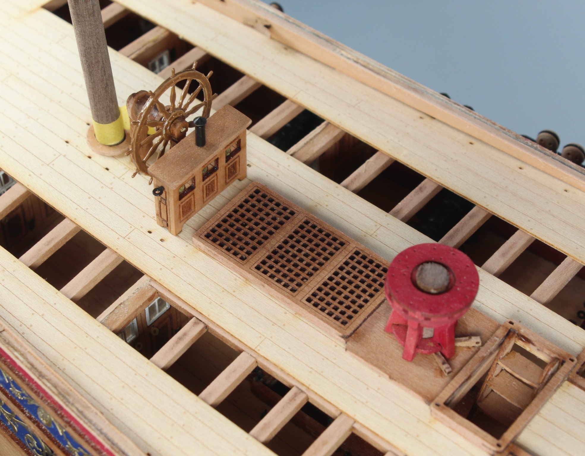
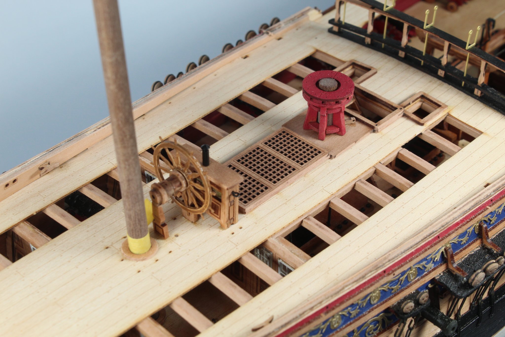
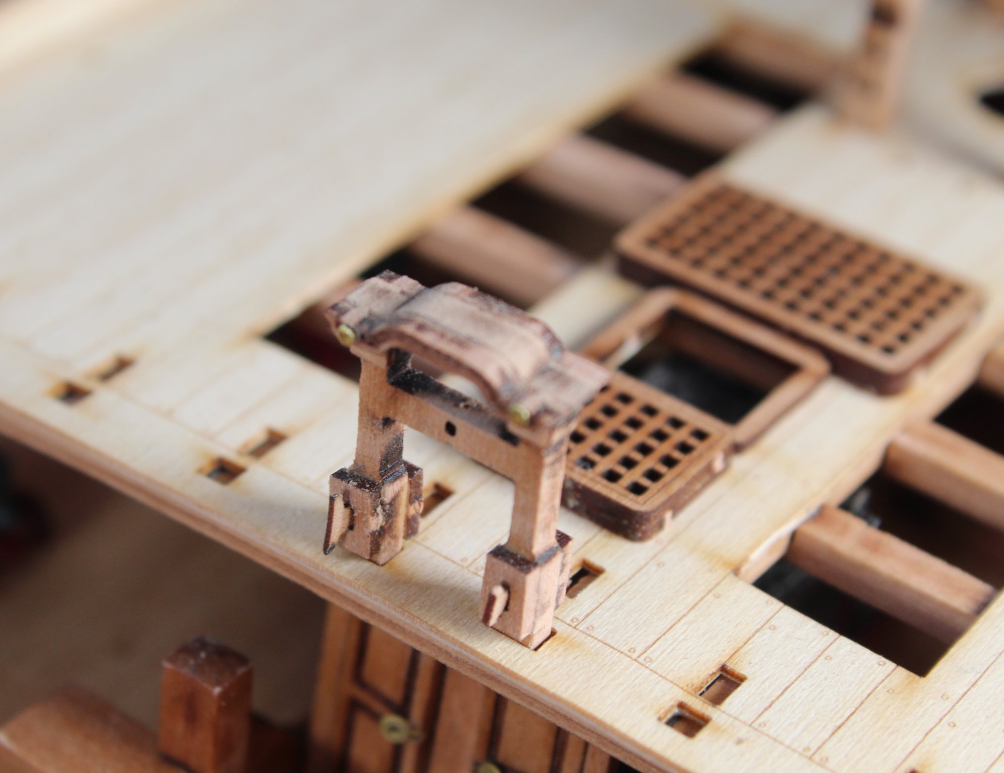
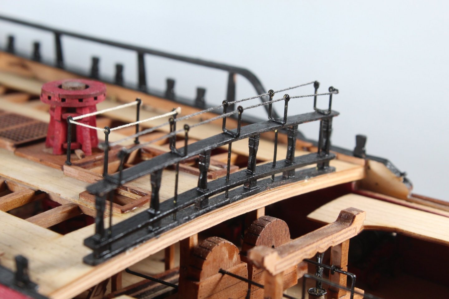
Work is progressing nicely on the V1 HMS Sphinx build, as can be seen in the photo below I believe I have now completed all the work on the quarterdeck. This is a close up of the quarter gallery and rail. This shows the hammock cranes. I have also added the rope round the ladder hatch This shows the capstan, binnacle and ships wheel I have added the gangway knees, the gangway deck is only dry fitted at the moment. I have done quite a bit of work on the forecastle. I just need to fit the catheads, gunwales, timberheads and hammock cranes.


-
Caldercraft Fittings Ship Boat hulls (cornwallmodelboats.co.uk)
-
Many thanks, it is only the stern fascia and quarter galleries I am unhappy with which was all down to an alignment mistake on my part
-
Yours look great and I think will be much better than my first attempt.
-
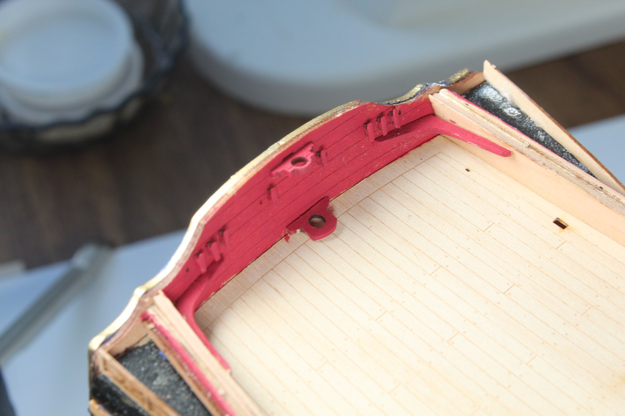
My work on the Sphinx has been a bit haphazard as I have not been following the build manual in sequence. I decided to concentrate my efforts on the Quarterdeck. To that end I have almost completed the work in this respect. The following picture shows the current progress in this respect. I am currently partway through work on the breast rail assembly. The beams and stanchions have been fitted. I did sand the stanchions pillars to try to get a rounded effect. I have only dry fitted the hammock cranes and the top beam but as can be seen every fits together perfectly. I have added the items to the inside of the stern fascia panel and painted in red, there is a slight bit of paints spillage but I am not overly concerned about that for this build. I have not painted the inner bulwarks red but I will on the V2 build. The next two pictures shows quarterdeck deck furniture. The tape on the mizzen mast indicates that the dowel has been fully engaged through the holes in the lower decks. The eyebolts, deck cleats and gunwales are still to be added. The gangway deck patterns have been dry fitted in the next photo. I do need to trim the gangway patterns to allow for the fitting of the gunwales, as per build instructions 551 - 553. I also have to paint ands fit the gangway support knees to the inner bulwarks. The forecastle bow inner bulwarks have been soaked in hot water for 30 minutes and bent. They have been clamped for 48 hours so far, The clamps will be removed once I ready to start work in this area which should be in the next few days. The bell tower has been built and is only dry fitted for the time being, noting I have not added the bell or bell handle as this assembly need to be painted black. There is also a bit more work removing some laser char before painting. The bitts are glued in place and ready for the crossbeams to be fitted. The coaming has been dry fitted, noting I do have to sand the laser char from all the visible edges.


-
My righthand side of the Sphinx is the one I'll use for display purposes. I will also buy the bigger ship when it becomes available to add to my Vanguard Model collection.
-
You could always take my approach and buy a second kit🤣, yours look much better than mine however so I am sure you can fix the issues. I am currently working on the quarterdeck and forecastle on my V1 kit, as soon as that is complete I will start work on the v2 kit
-
Ron I do need to learn how to measure. I have learnt such alot from the first build so I am hoping the 2nd build will be much better, planning to start work on the v2 kit in the next couple of weeks, once I have finished with the forecastle and quarterdeck.
- 542 replies
-
- 3
-
-
- Sphinx
- Vanguard Models
- (and 3 more)
-
There is a slight gap on mine also, but I made a right mess when I installed the left hand side. I had to rip it off and reglue due to a misalignment on my part.
- 542 replies
-
- 3
-
-
- Sphinx
- Vanguard Models
- (and 3 more)
-
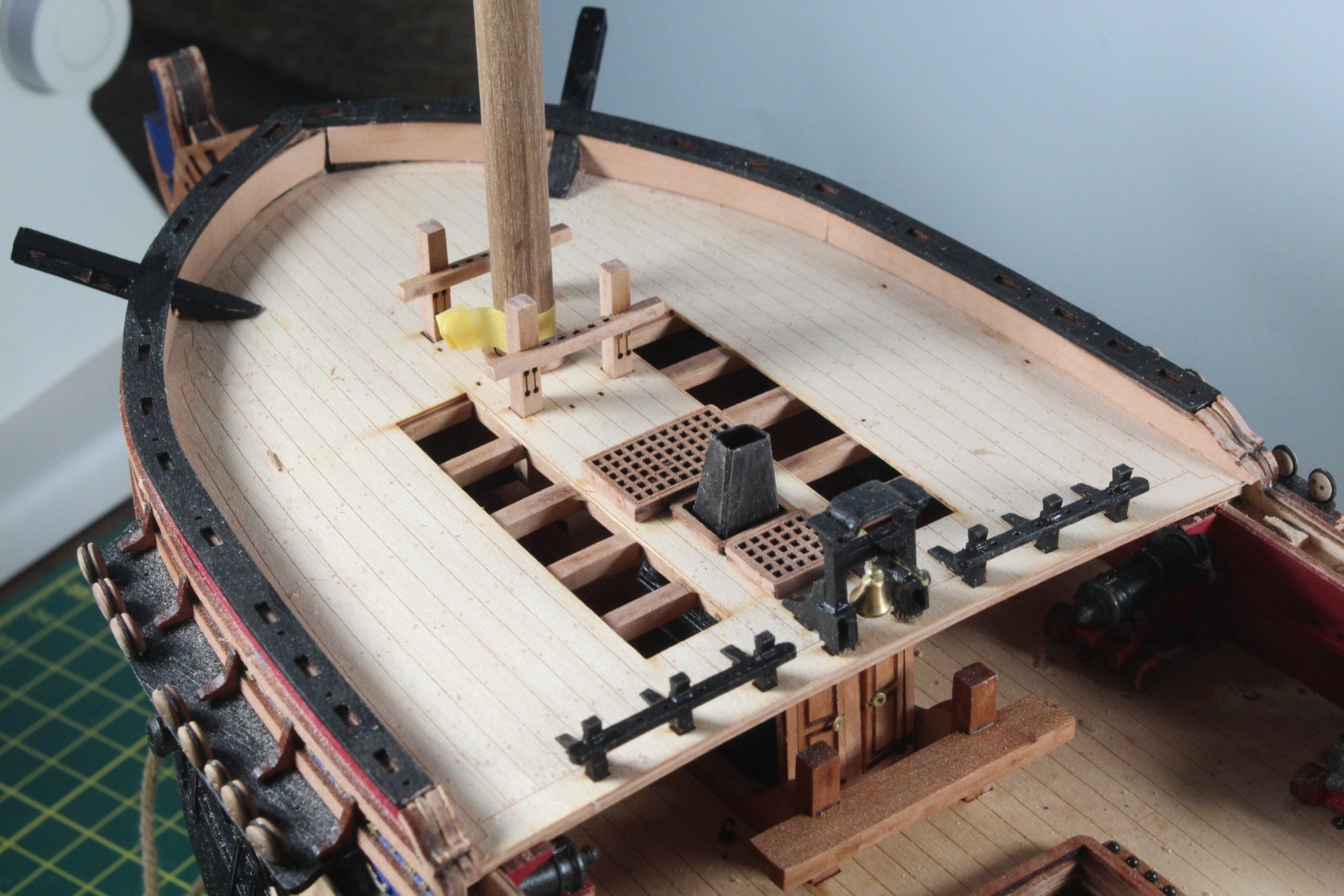
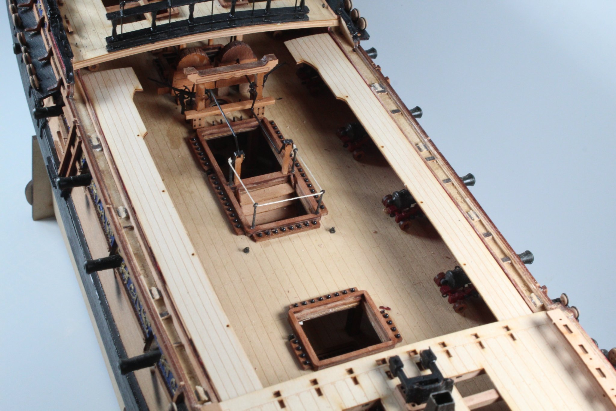
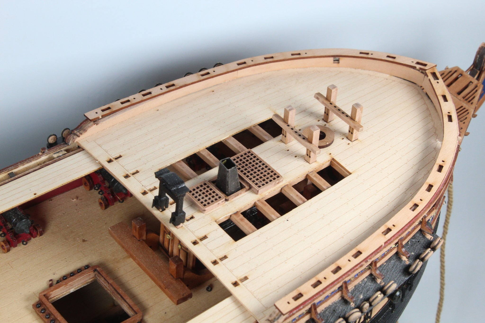
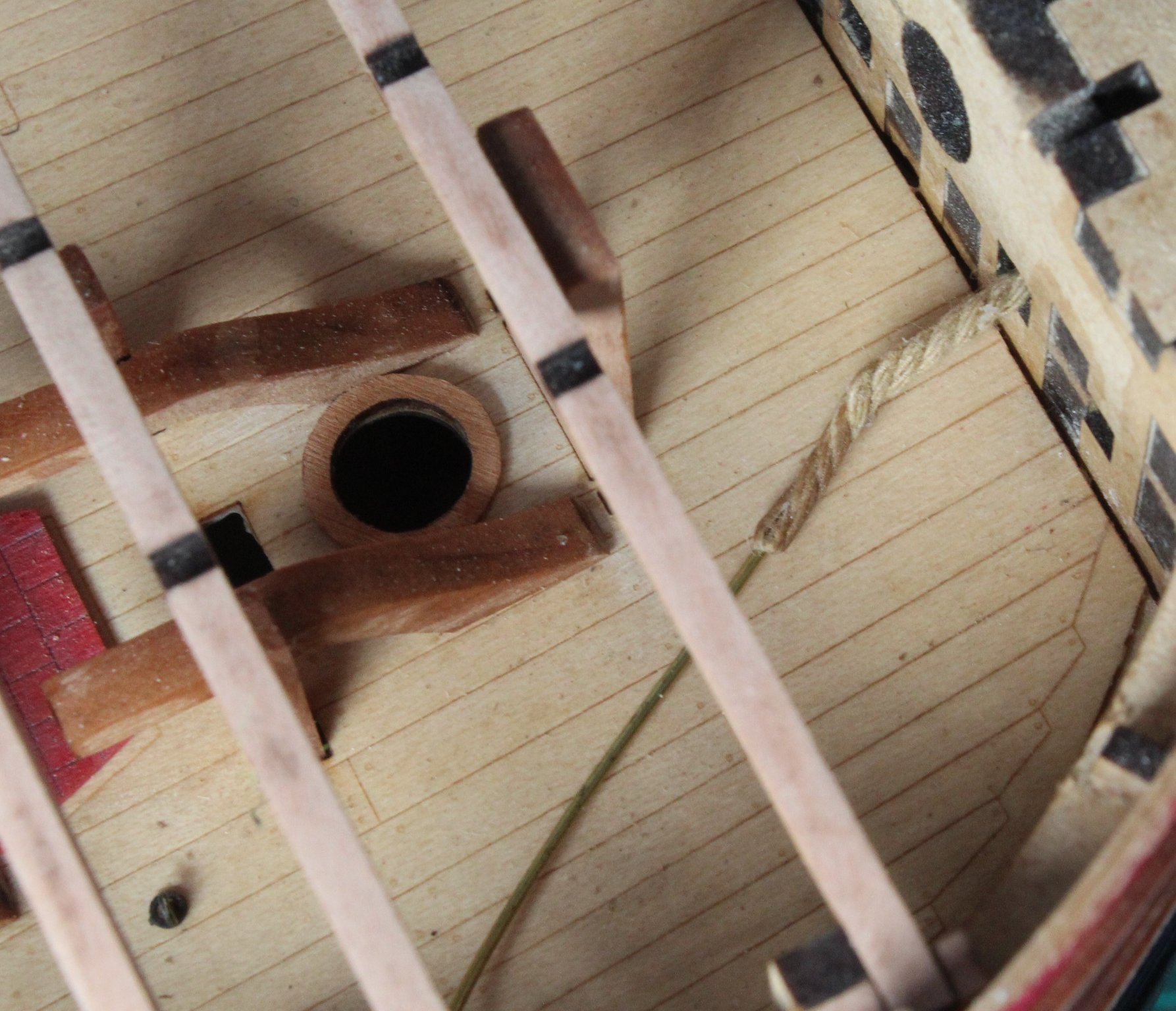
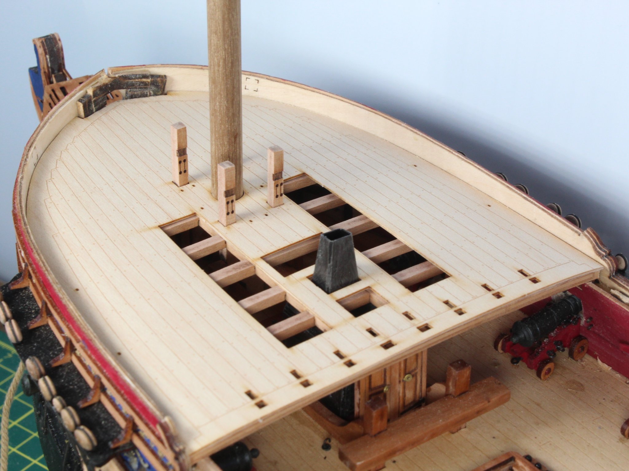
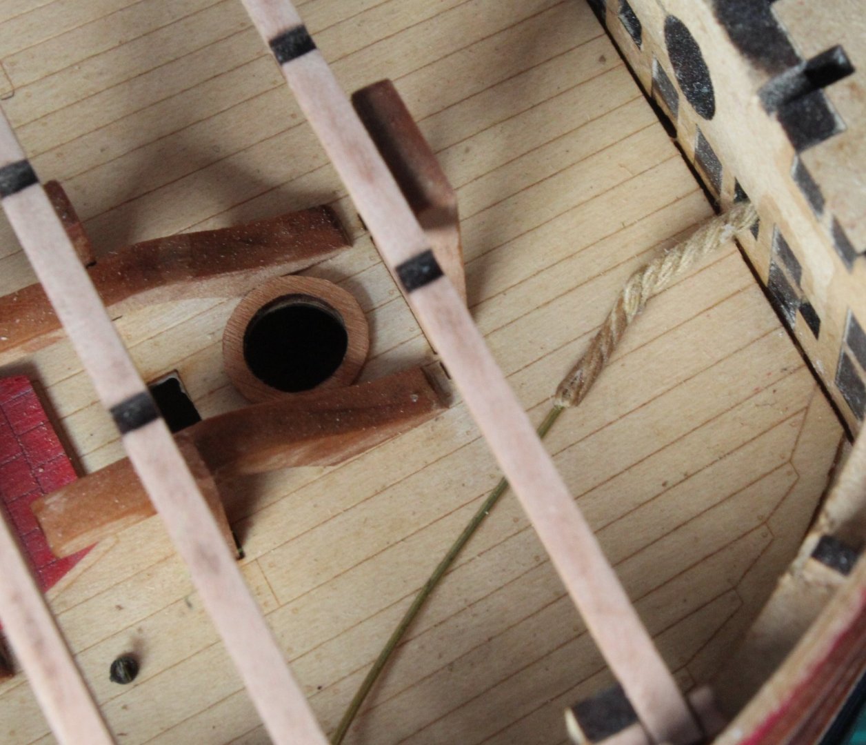
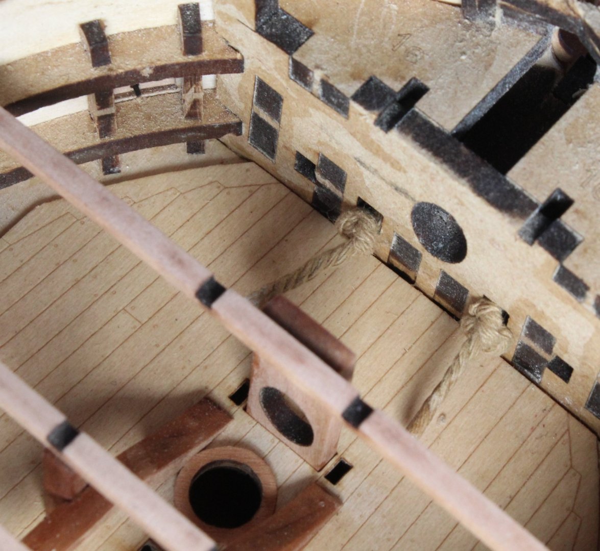
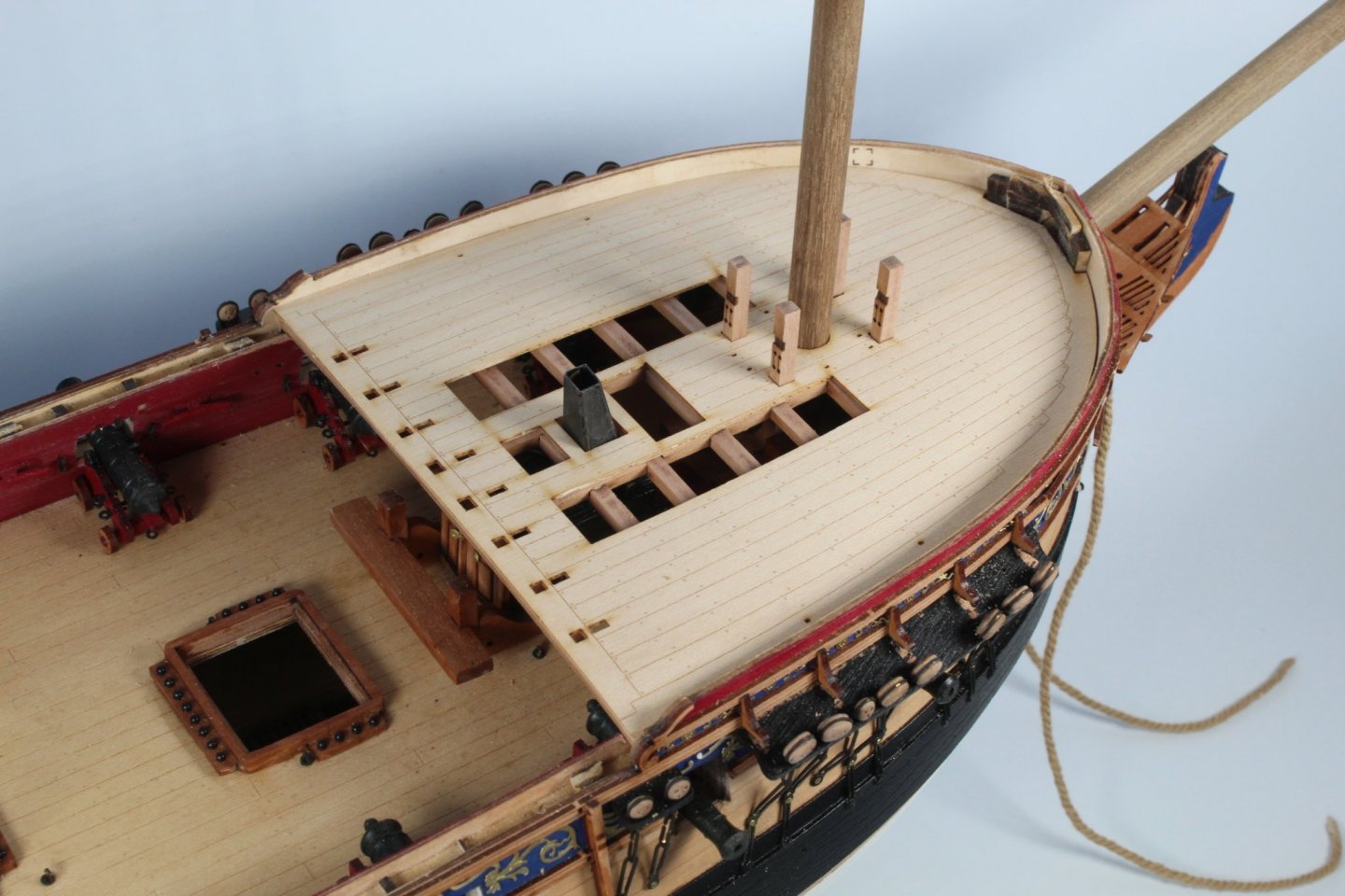
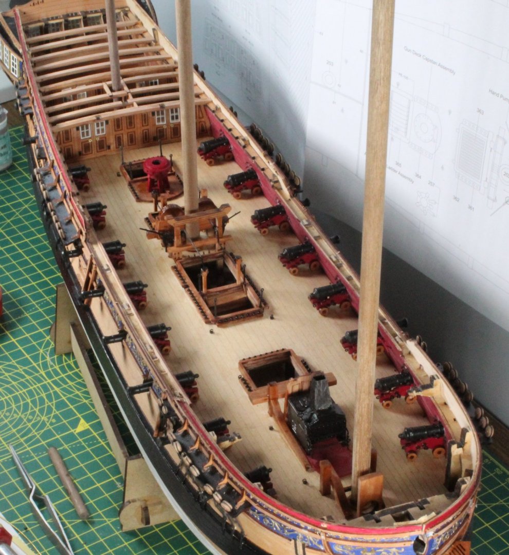
The first task today was to install the anchor cable into position. This has to be fed through the hawse hole to the inner pair of bulkhead holes. I used a brass rod which I shaped so it would go through the two holes. I put a touch of ca gel on the end of the anchor rope and then pushed the brass rod into the end. It was then a very easy task to feed the rope through the two holes. Once both cables were installed I added a knot to ensure the cable would remain in place. This picture shows the first anchor rope in position with the brass rod still in place. The next picture shows both anchor cables in position with the knots in place. A view of the cable in hawse holes. The anchor cable was fed through the holes nearest the bowsprit The next task was to check if the 8mm bowsprit dowel would fit. I started this task by rotating (by hand) a 7mm, then a 7.5mm and finally an 8mm drill bit. I then used my large round file to gently file the opening a tad bit more. This picture shows the dowel in place through the two angled holes This picture shows the Sphinx fitted with the Mizzen, Main, and Fore mast dowels on place along with the bowsprit dowel. I have also sanded the laser char from all the forecastle beams which have now been glued in place. The forecastle deck pattern was then dry fitted. The edges did not require too much sanding to get a good fit. To ensure the forecastle deck properly positioned during the sanding process you will note that the bitts, mast and stove chimney were positioned as the deck was added to the deck. The deck is only dry fitted at the moment. I repeat the process with the quarterdeck pattern, using the mizzen mast and capstan dowel to aid the correct alignment of the quarterdeck deck Finally a picture of the Sphinx with the decks in place along with all the masts and bowsprit.


-
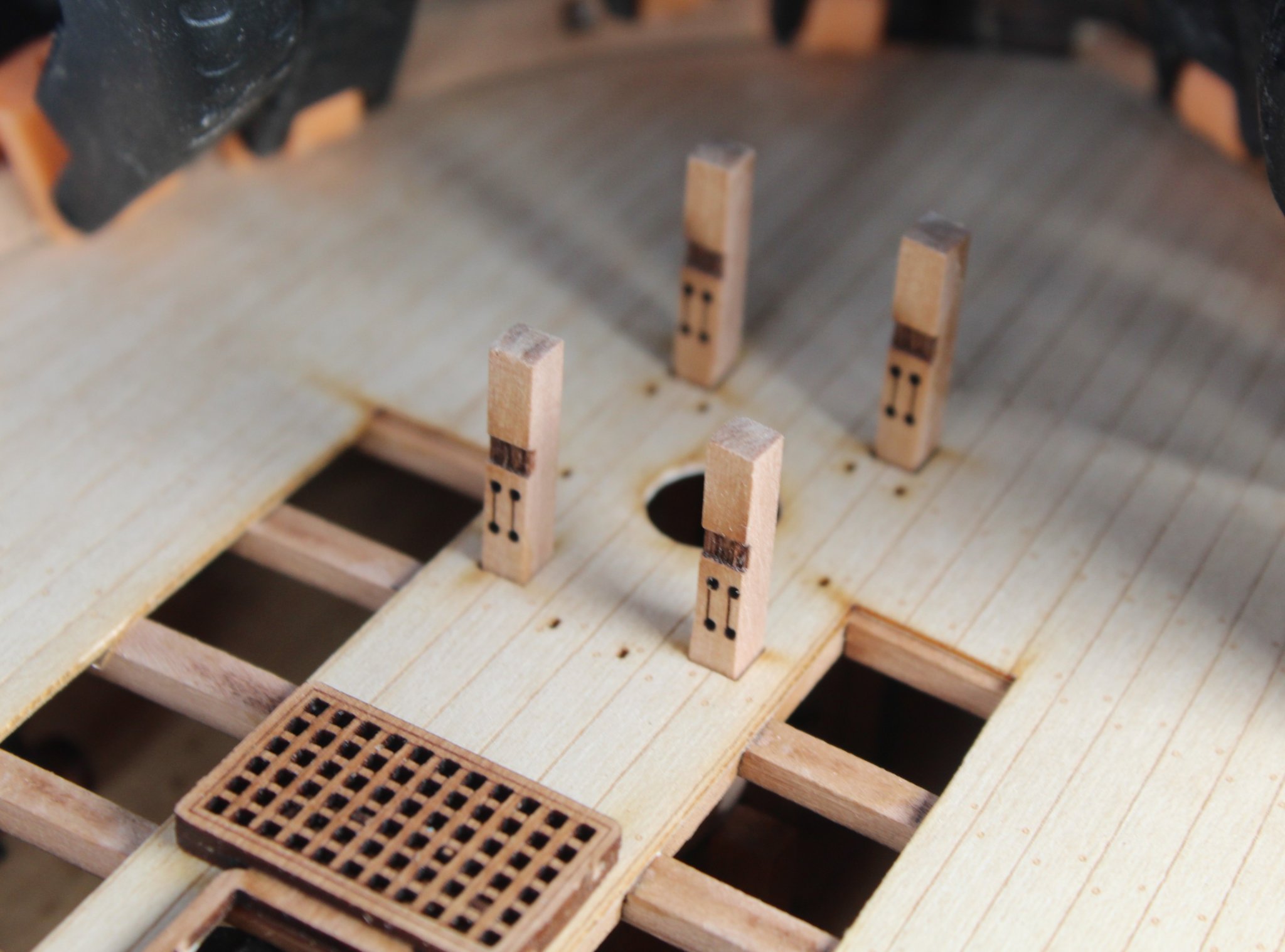
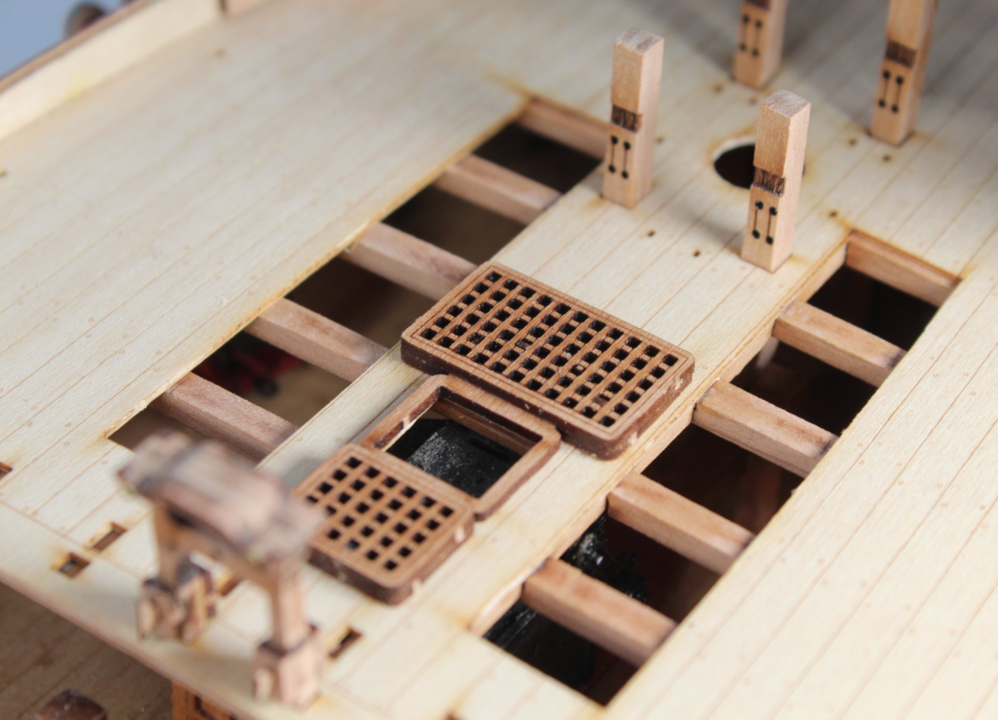
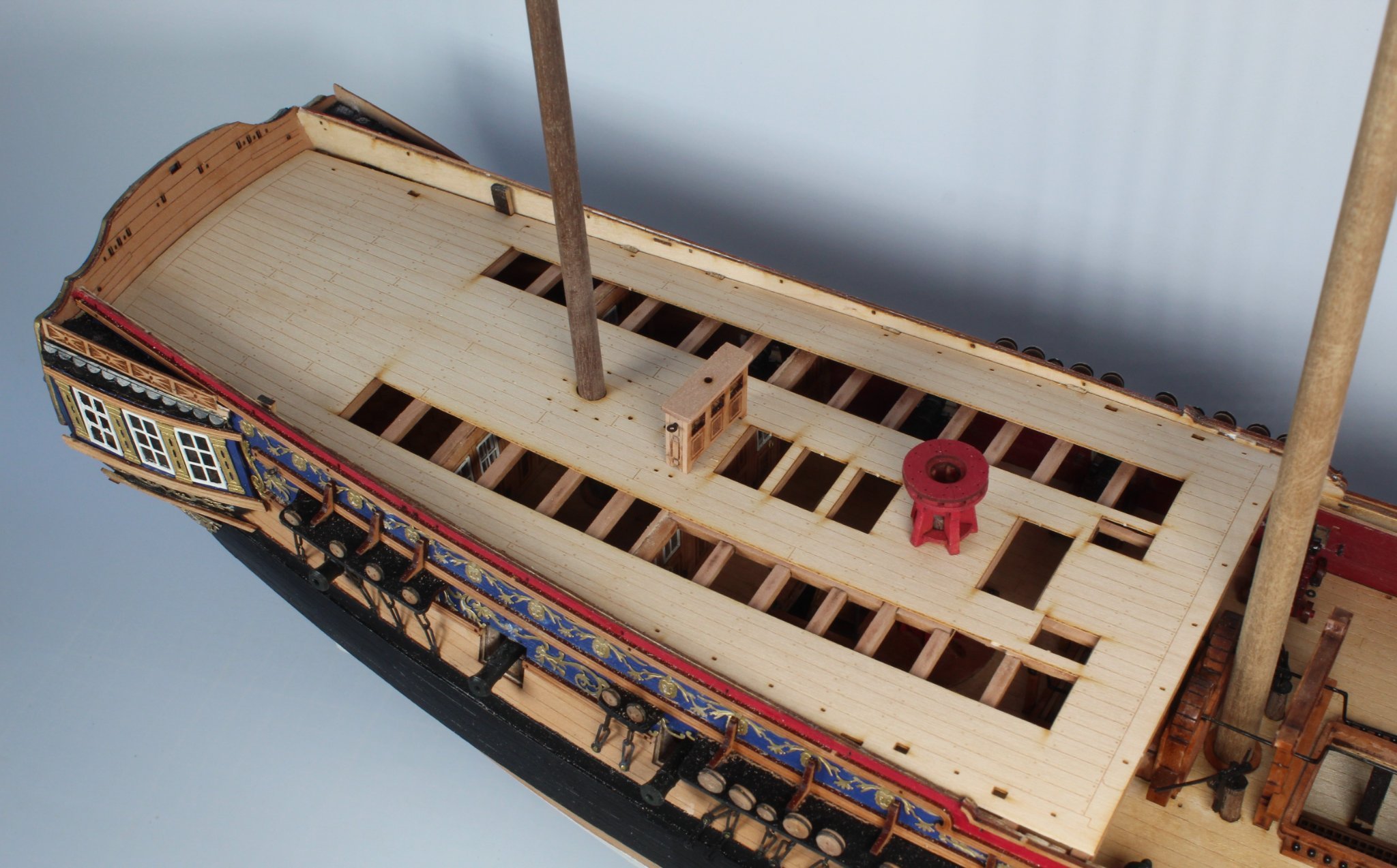
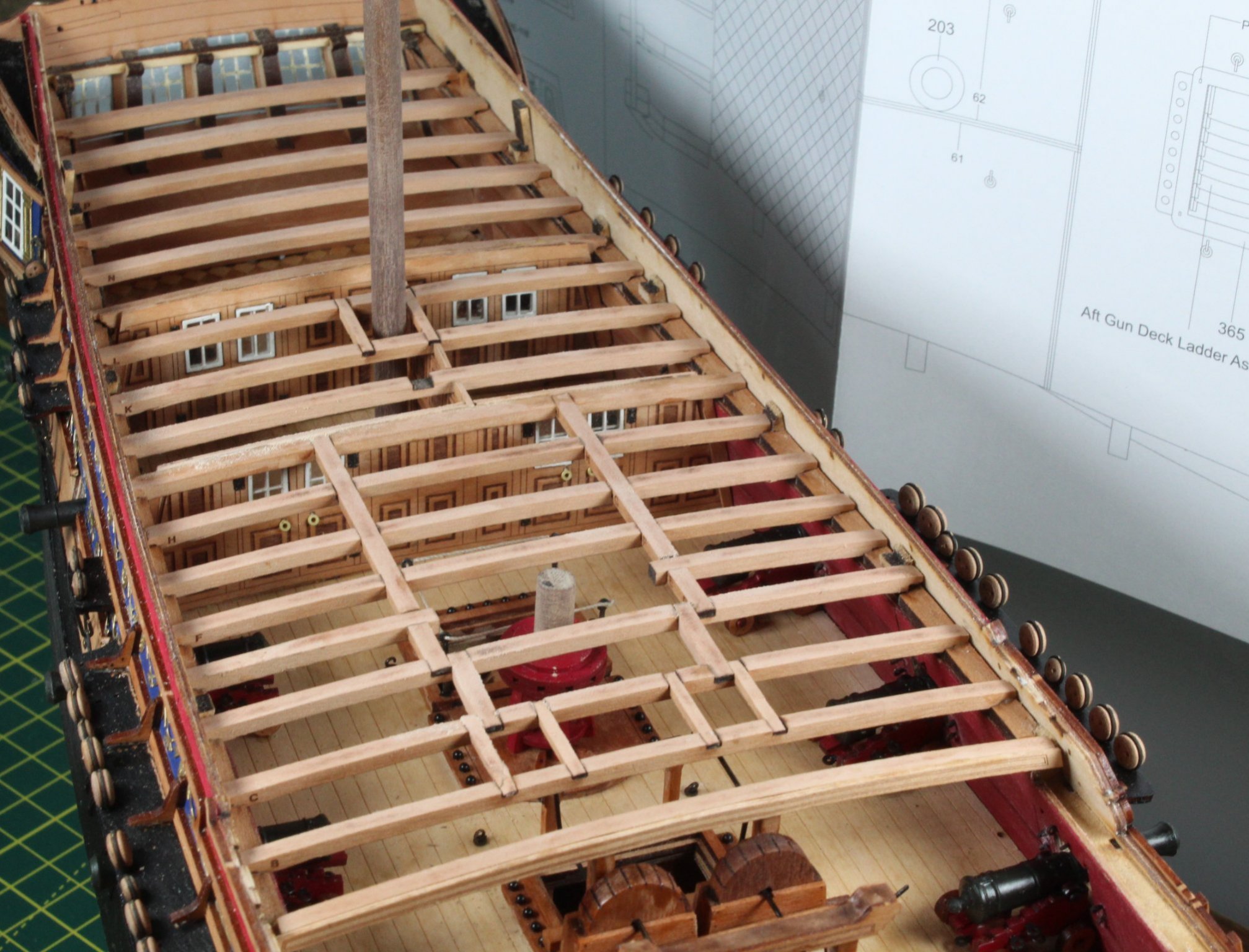
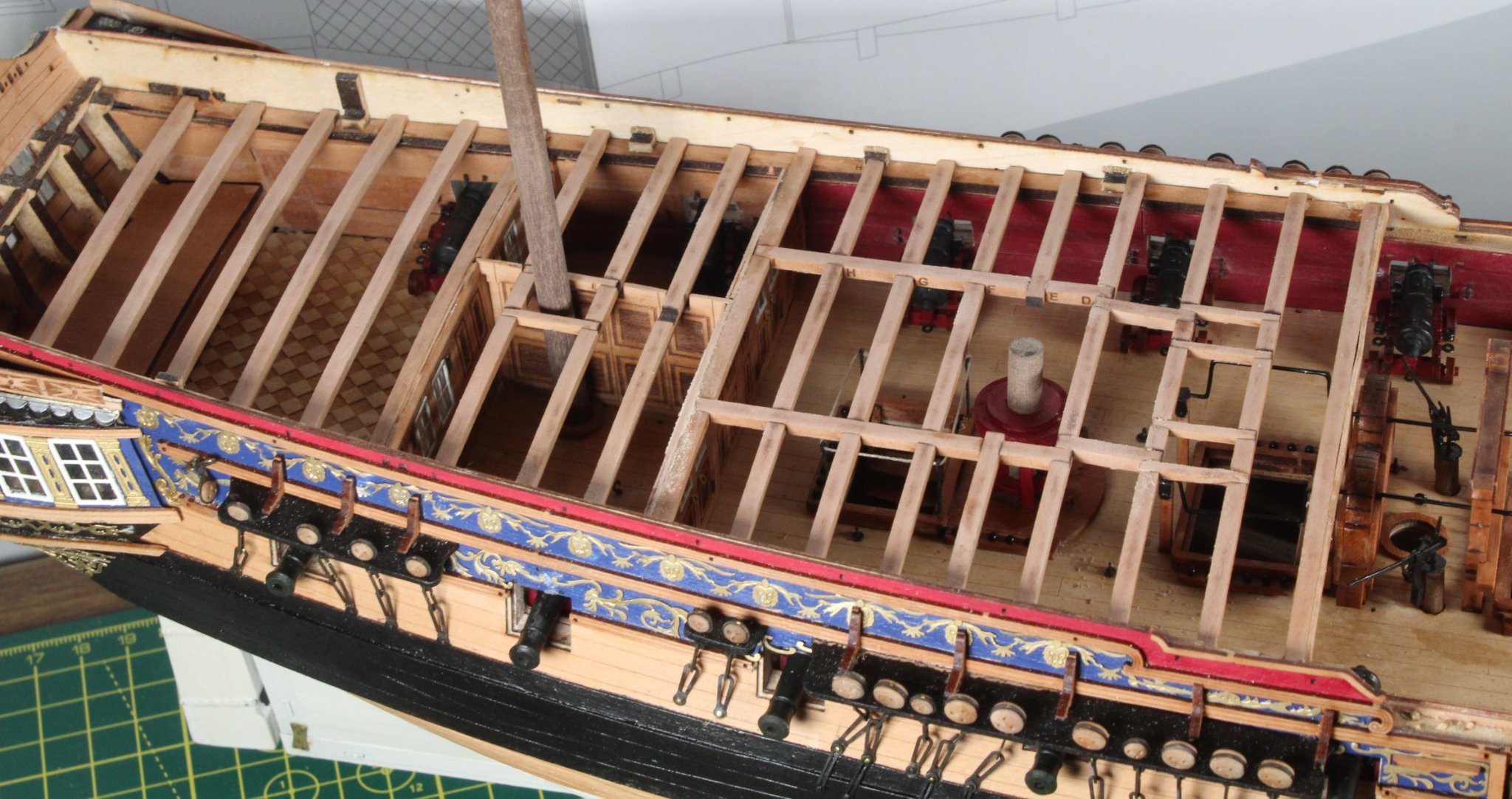
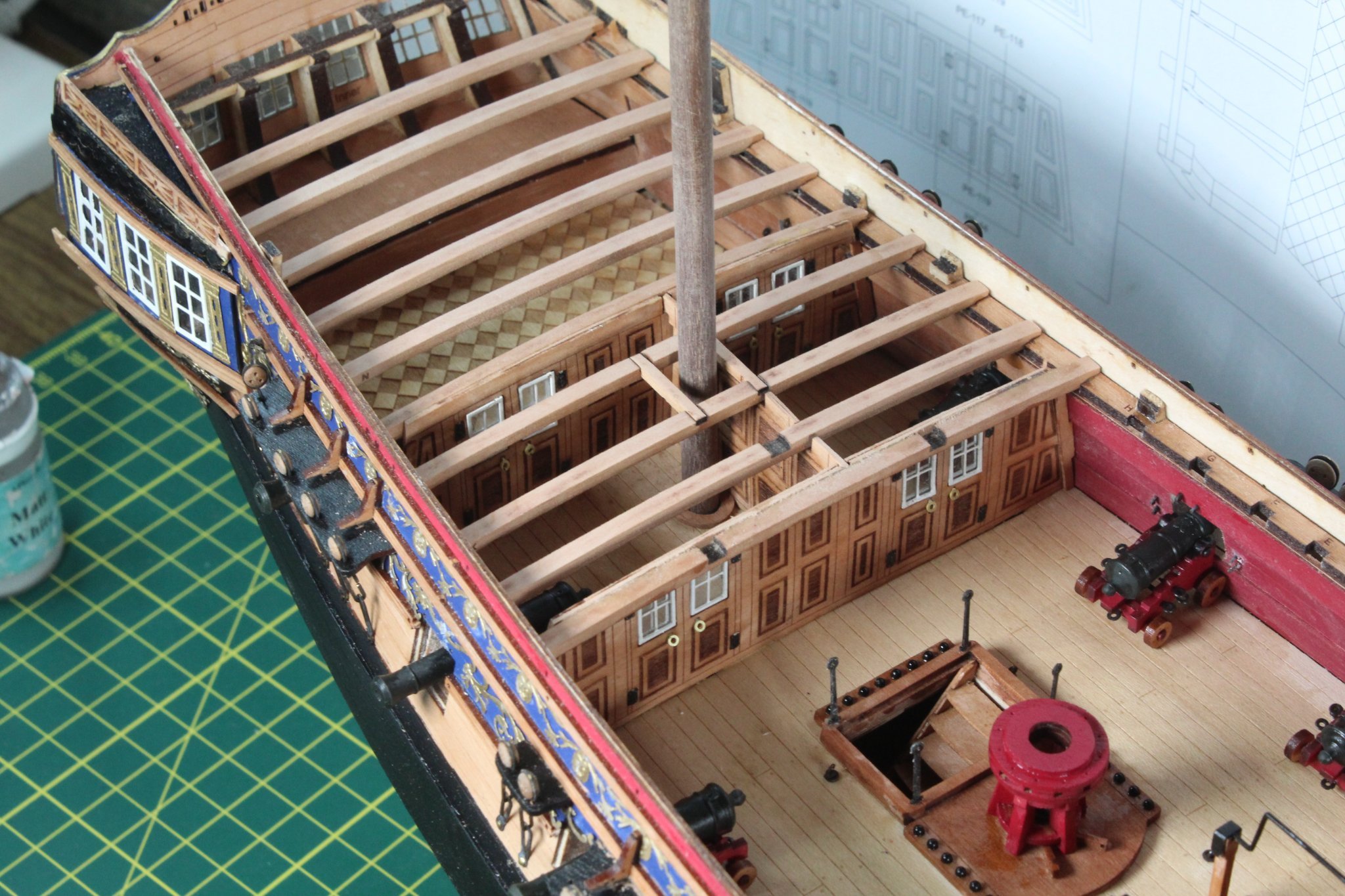
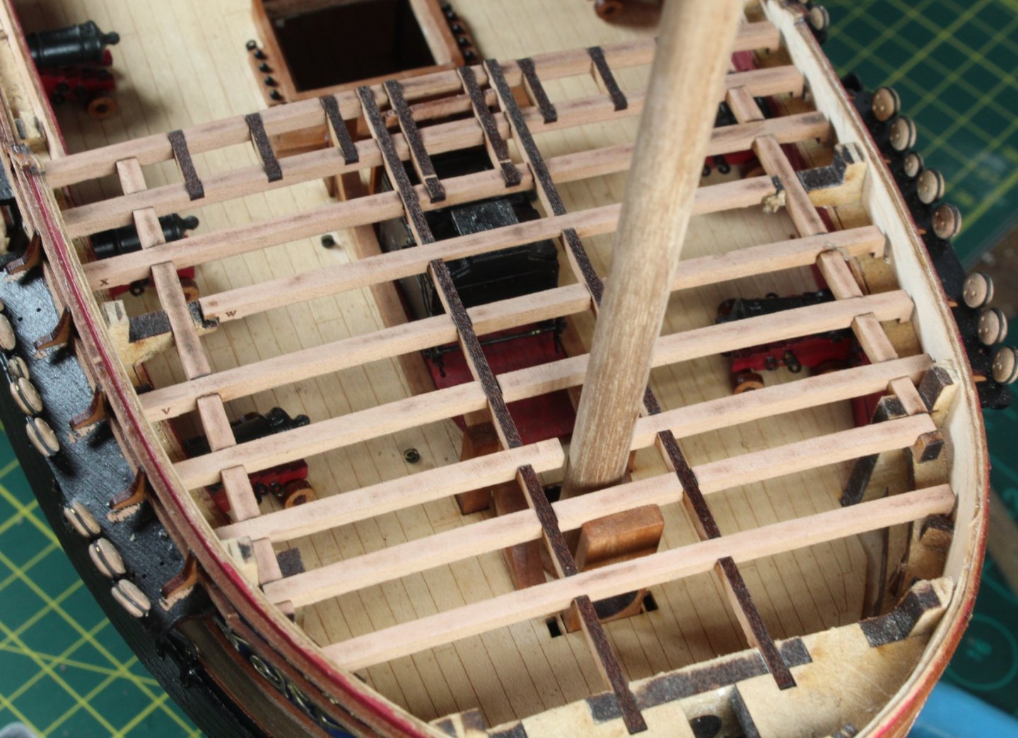
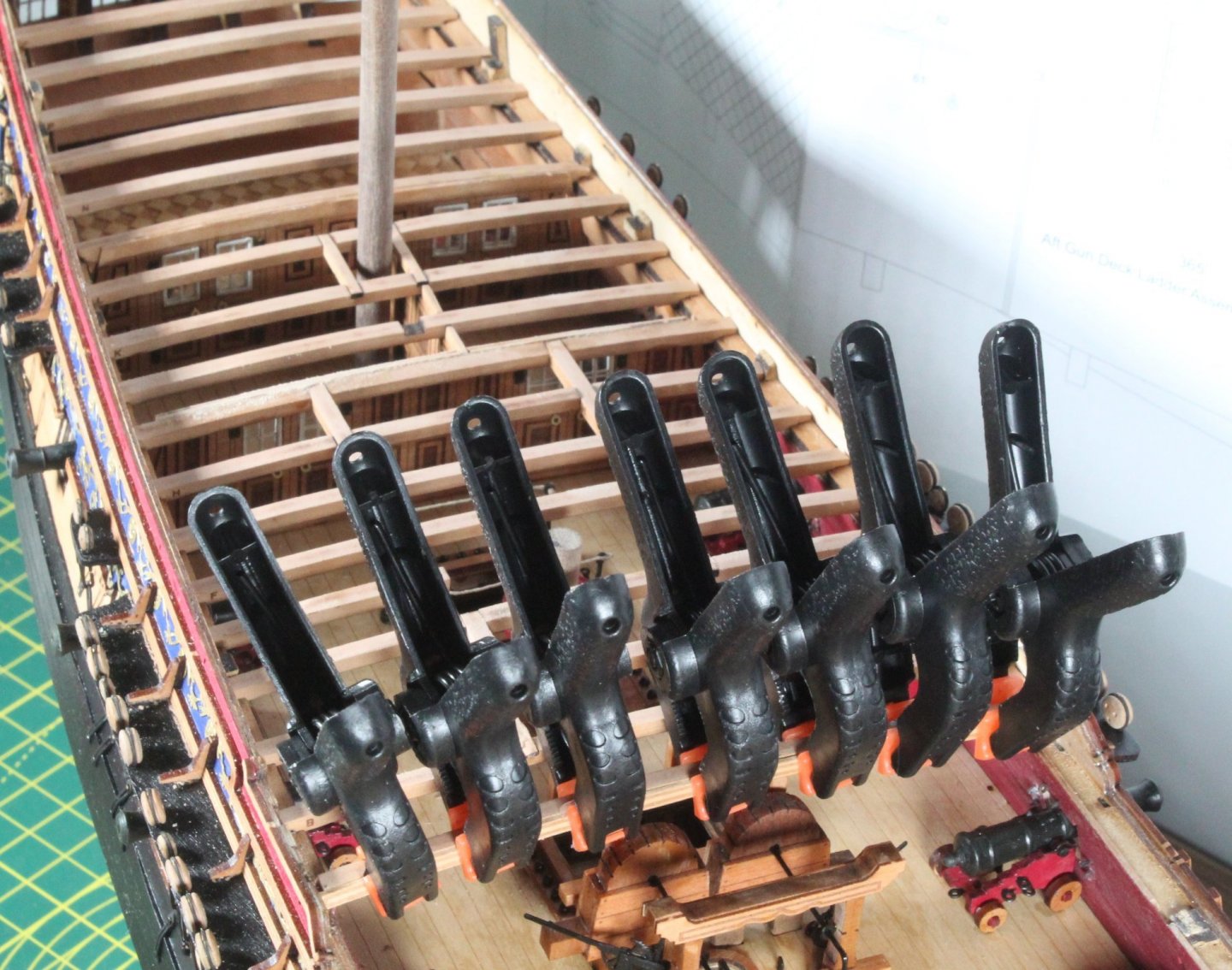
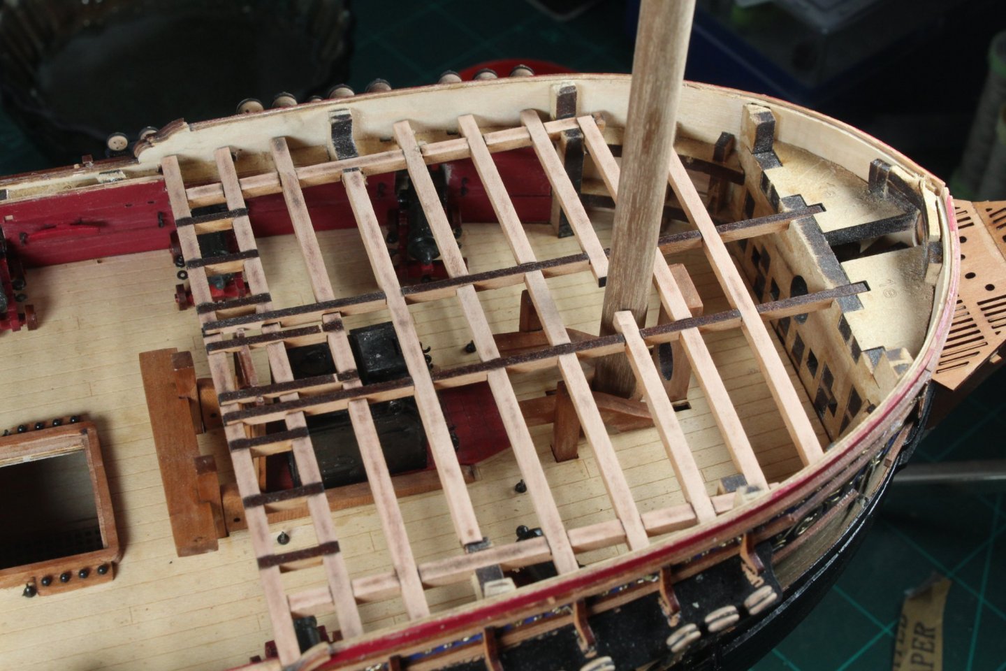
Today I have been working in fitting the quarterdeck beams, which was a fairly easy task to complete. Once the beams were in place the pattern for the leading quarterdeck beam was added. The leading beam pattern has been glued and clamped in place All the quarterdeck beams are glued in place. I did add the thread around the coaming openings as can be seen in this photo I have also started work on the forecastle beams. The laser char has been removed from the beams, I will also remove the char from the longitudinal locking beams. Before the beams are glued in place I will feed the anchor rope through the their respective holes, hopefully this will be a fairly straightforward task. I will also need to sand the bowsprit opening, as necessary so the 8mm dowel can be located.


-
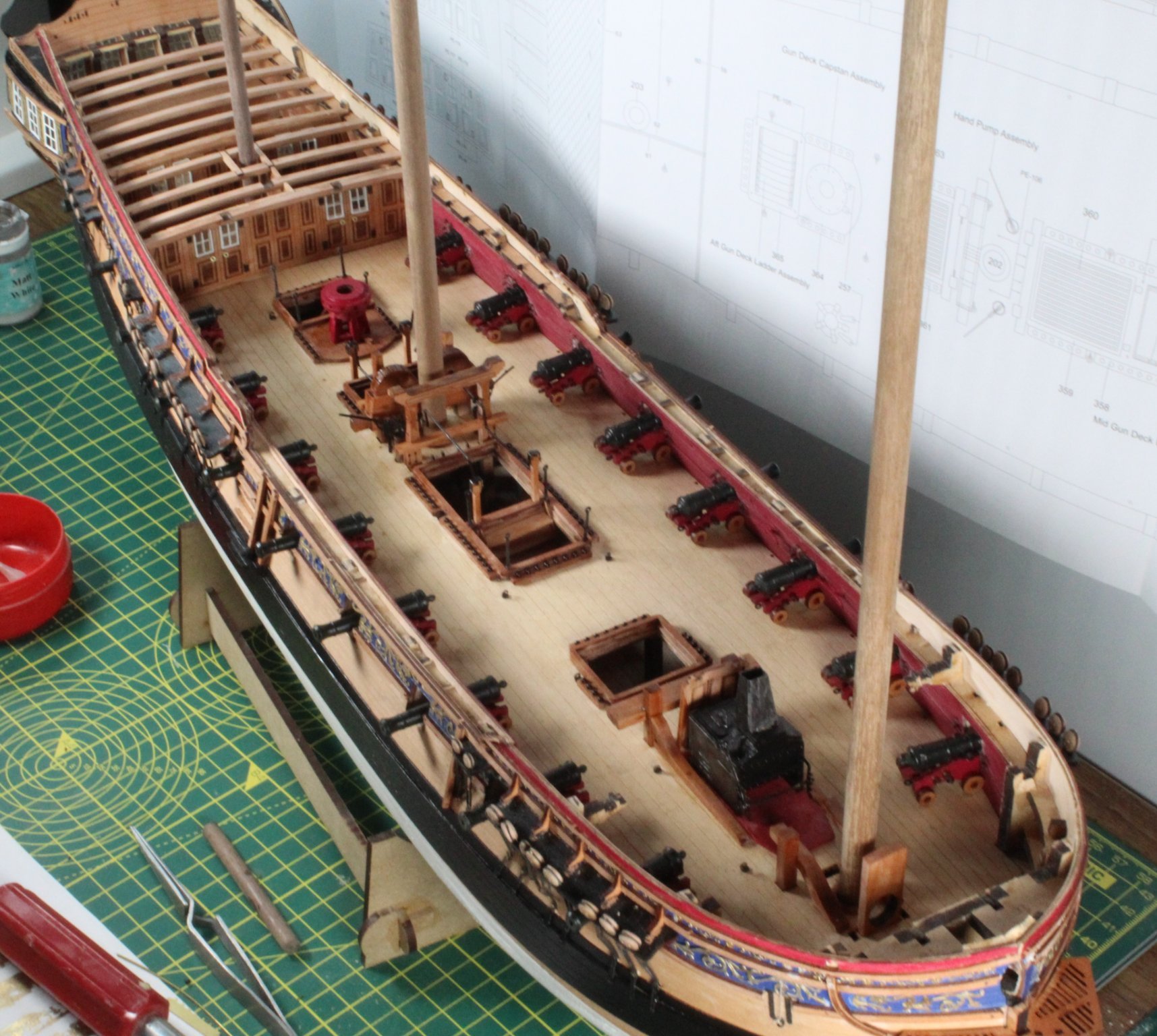
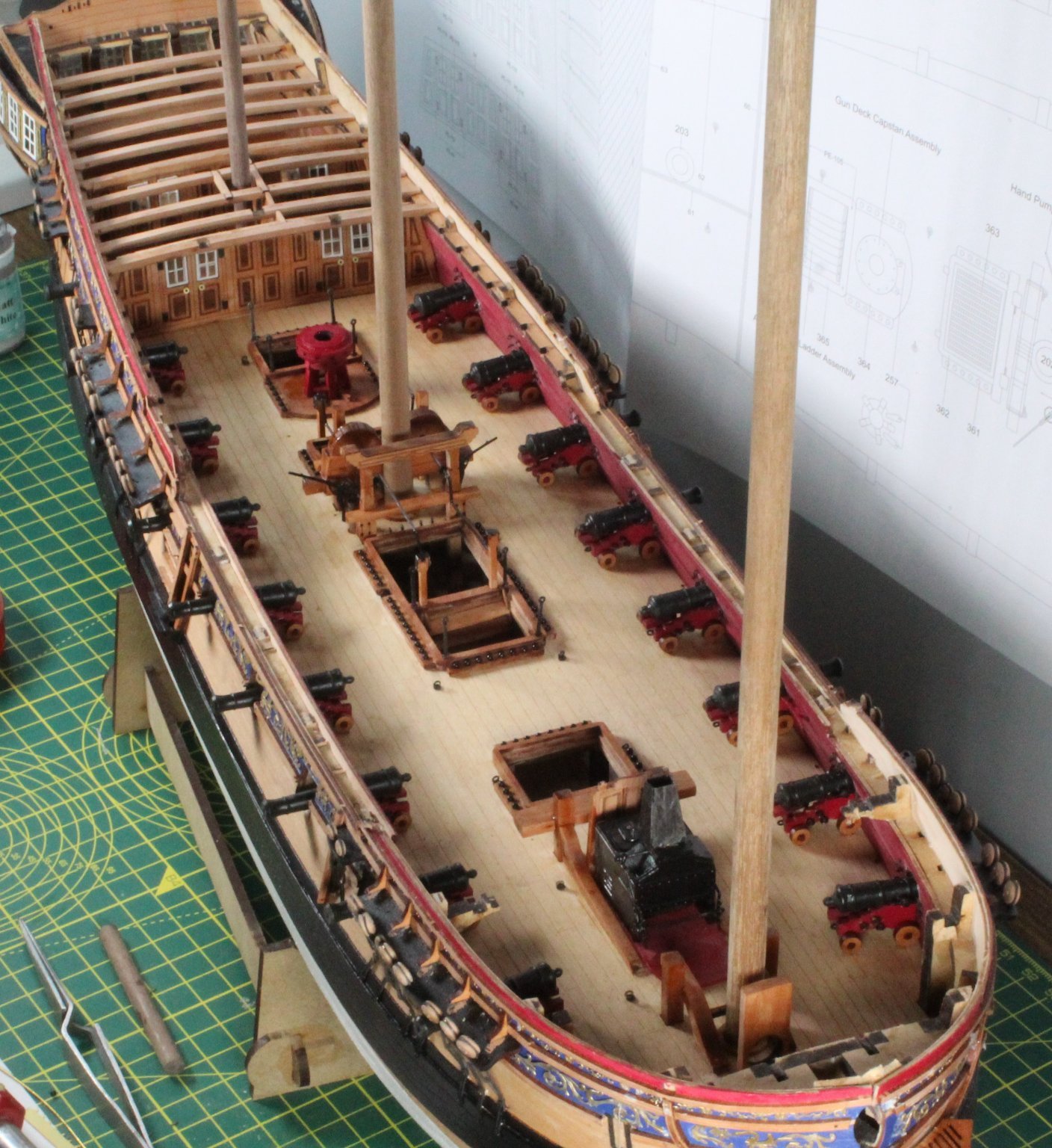
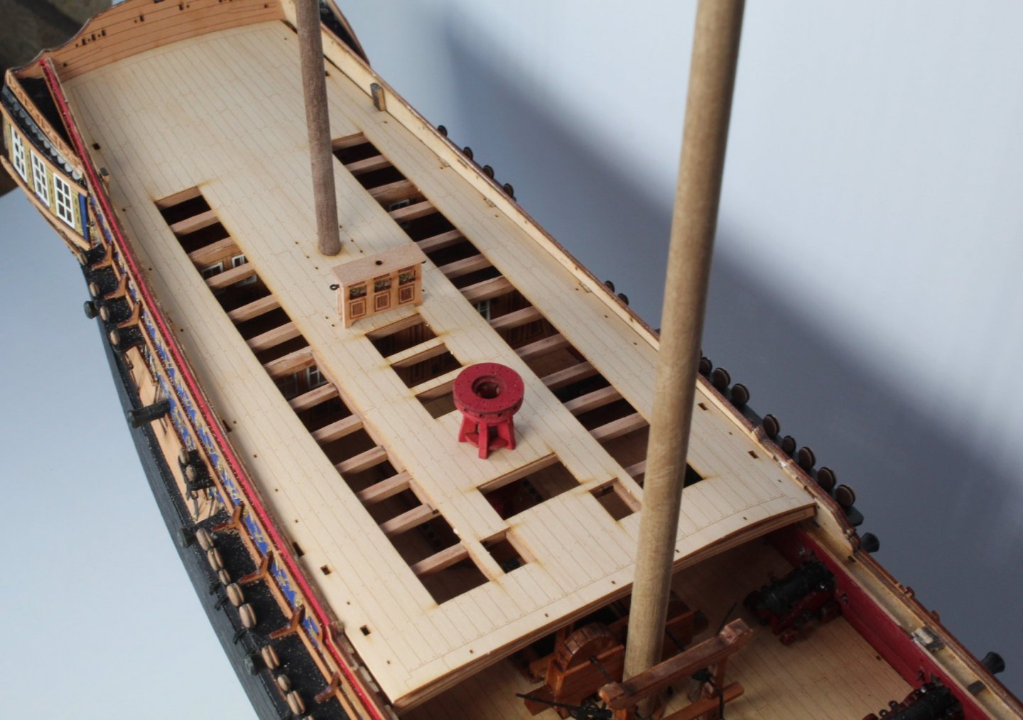
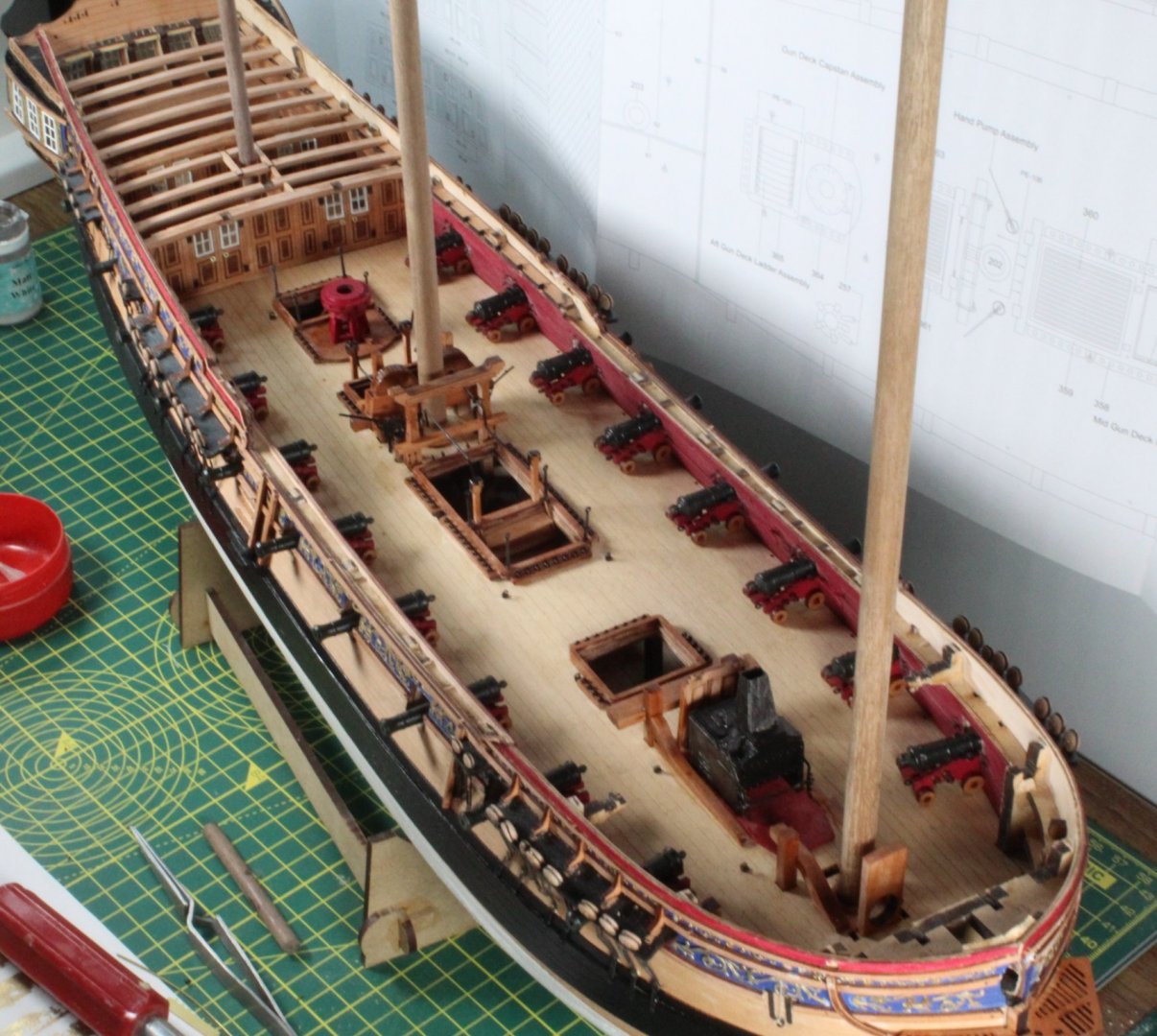
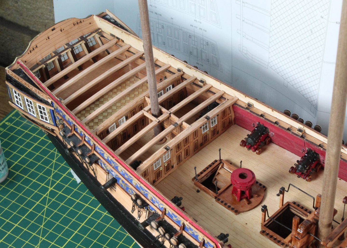
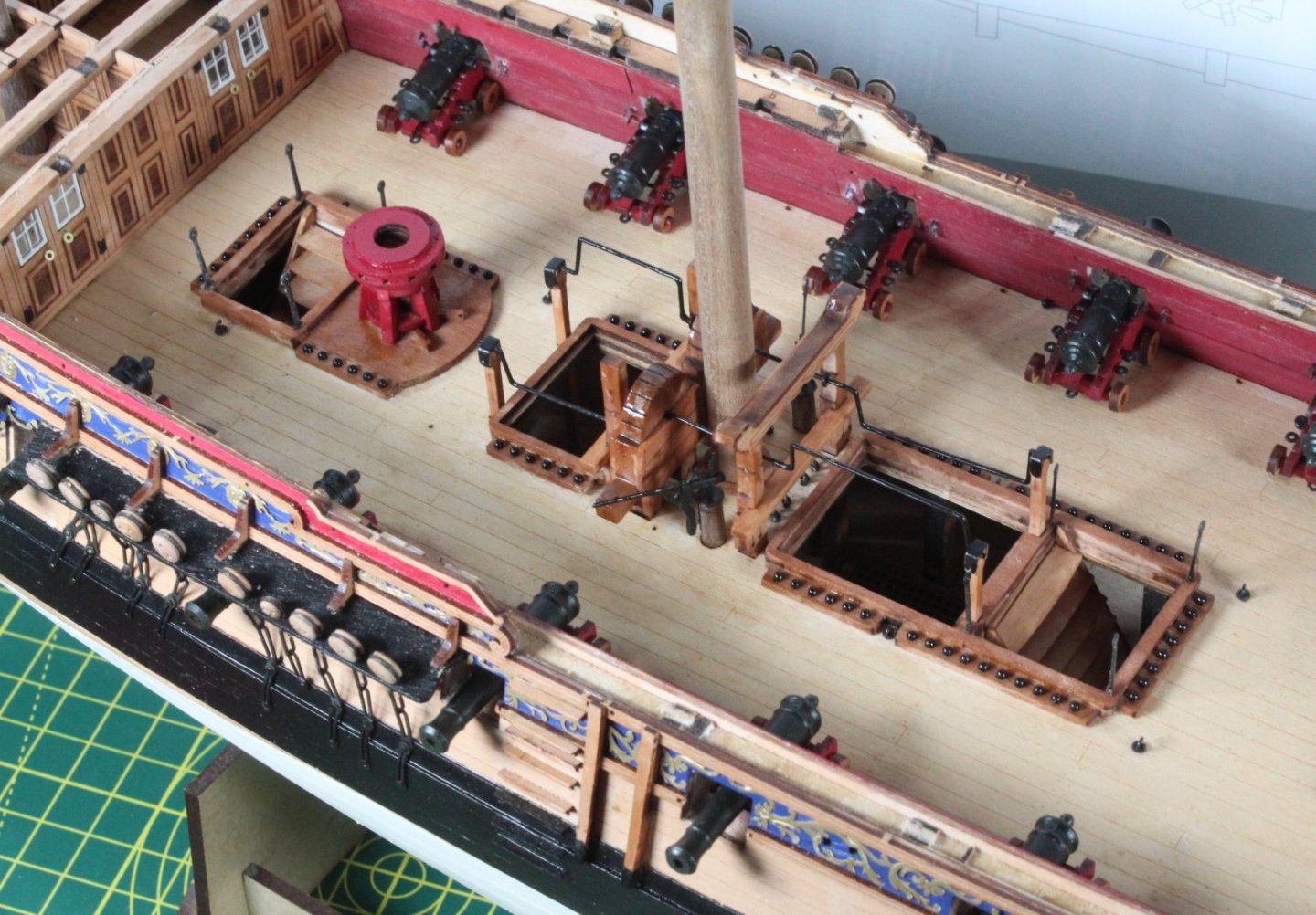
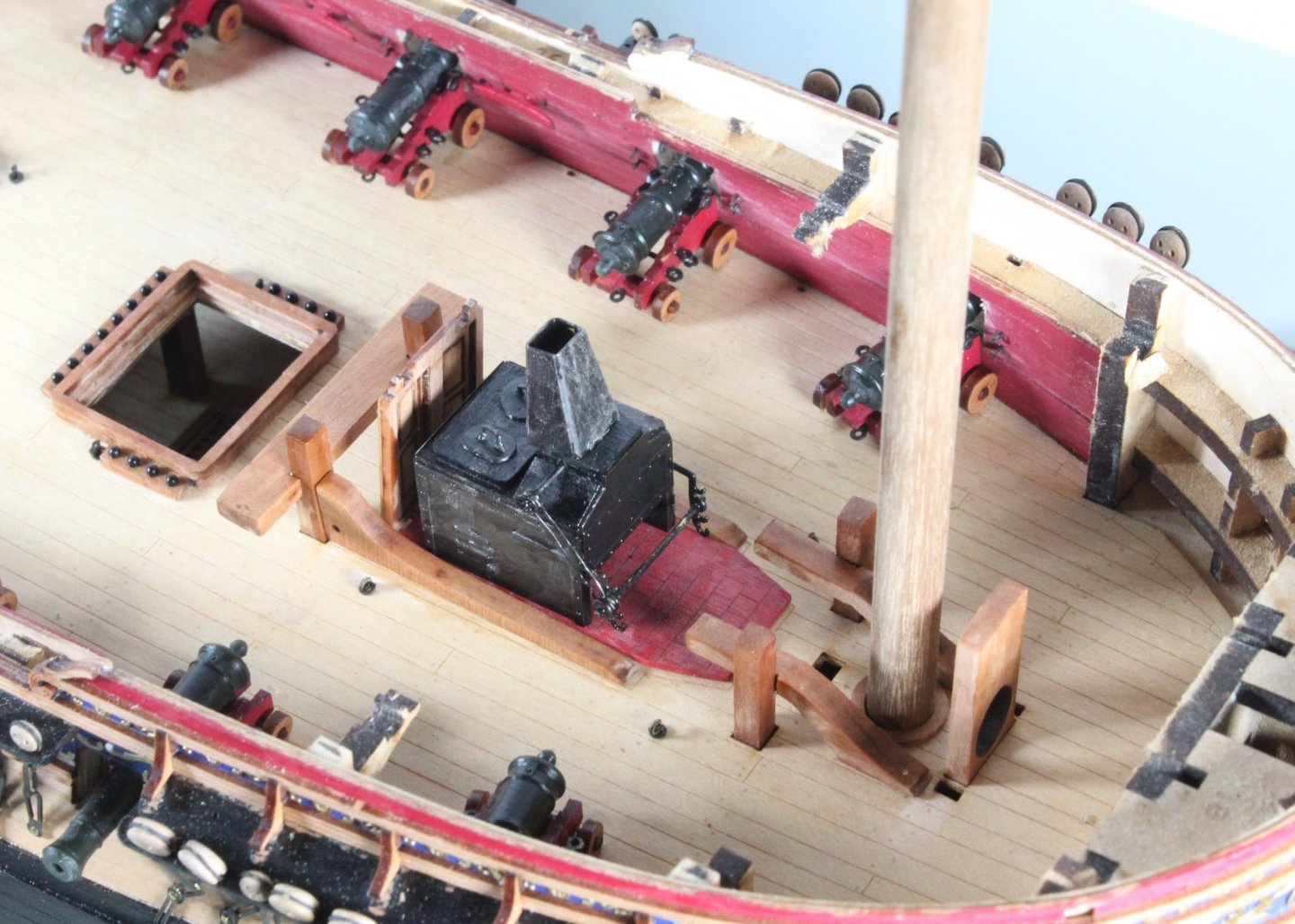
I have had a couple of quite days in the shipyard so not too much to report (as if🤣). Here are a few pictures of the current state of play. As you can see all the deck items have been added, I just need to run some 0.5mm natural thread through stanchions surrounding two coamings. I have also started to add the quarterdeck beams. The stern area. Midships Bow area. The stove chimney is only dry fitted, as it is fitted once the upper deck has been installed. I also need to work on the grey wash on the stove base method. I painted the pattern brick red, coated it with an acyclic varnish and then used a light grey wash which flowed nicely in the lines. However when I used a cotton bud to remove the excess wash, the excess wash remained on the base.

-
Due to my poor attempt at building the v1 so far (the kit is excellent but I need to improve my build skills) I have bought a v2 kit, which is currently waiting in the shipyard while I press on with completing the v1 kit.