Glenn-UK
-
Posts
3,169 -
Joined
-
Last visited
Content Type
Profiles
Forums
Gallery
Events
Everything posted by Glenn-UK
-
 Thank you. Enjoy your build like I have.
 -
Thanks Derek. I am very pleased. I have learnt so much in building this model. Your Soeedy log helped me a great deal.
-
Thanks Jim, it is a nice model, thankfully only I am fully aware of all the errors.
-
Many thanks, enjoy the build it is a fantastic model to build.
- 382 replies
-
- 1
-

-
- Vanguard Models
- Duchess of Kingston
- (and 1 more)
-
Many thanks Chris Cutter Alert up next
- 382 replies
-
- 1
-
-
- Vanguard Models
- Duchess of Kingston
- (and 1 more)
-
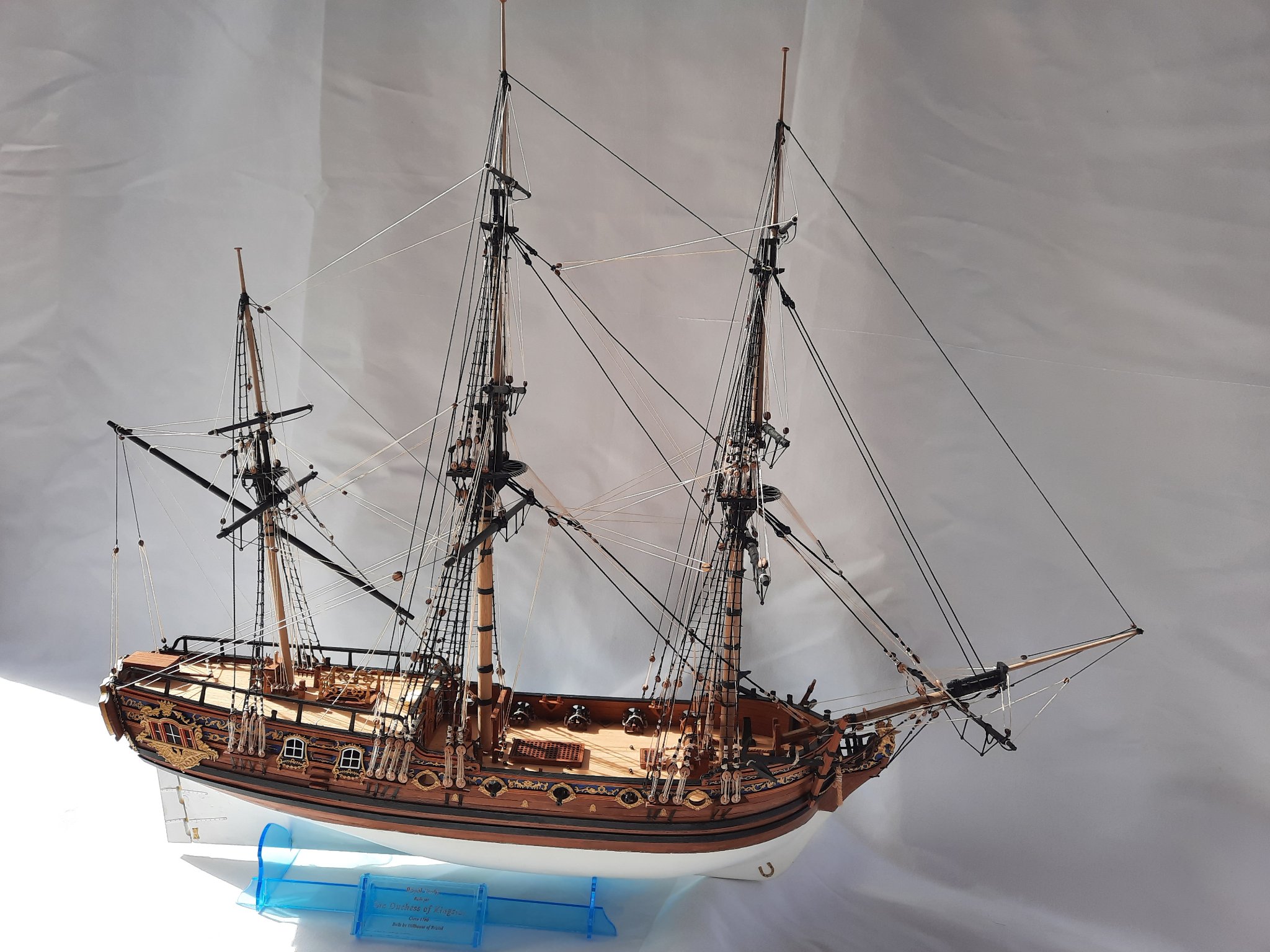
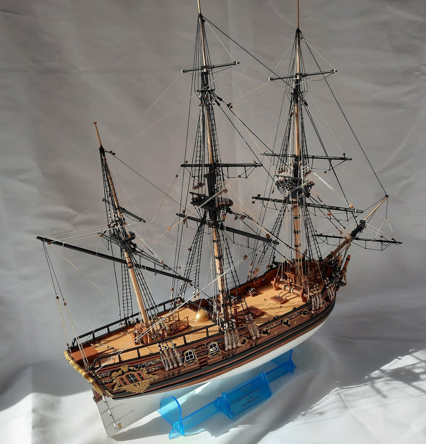
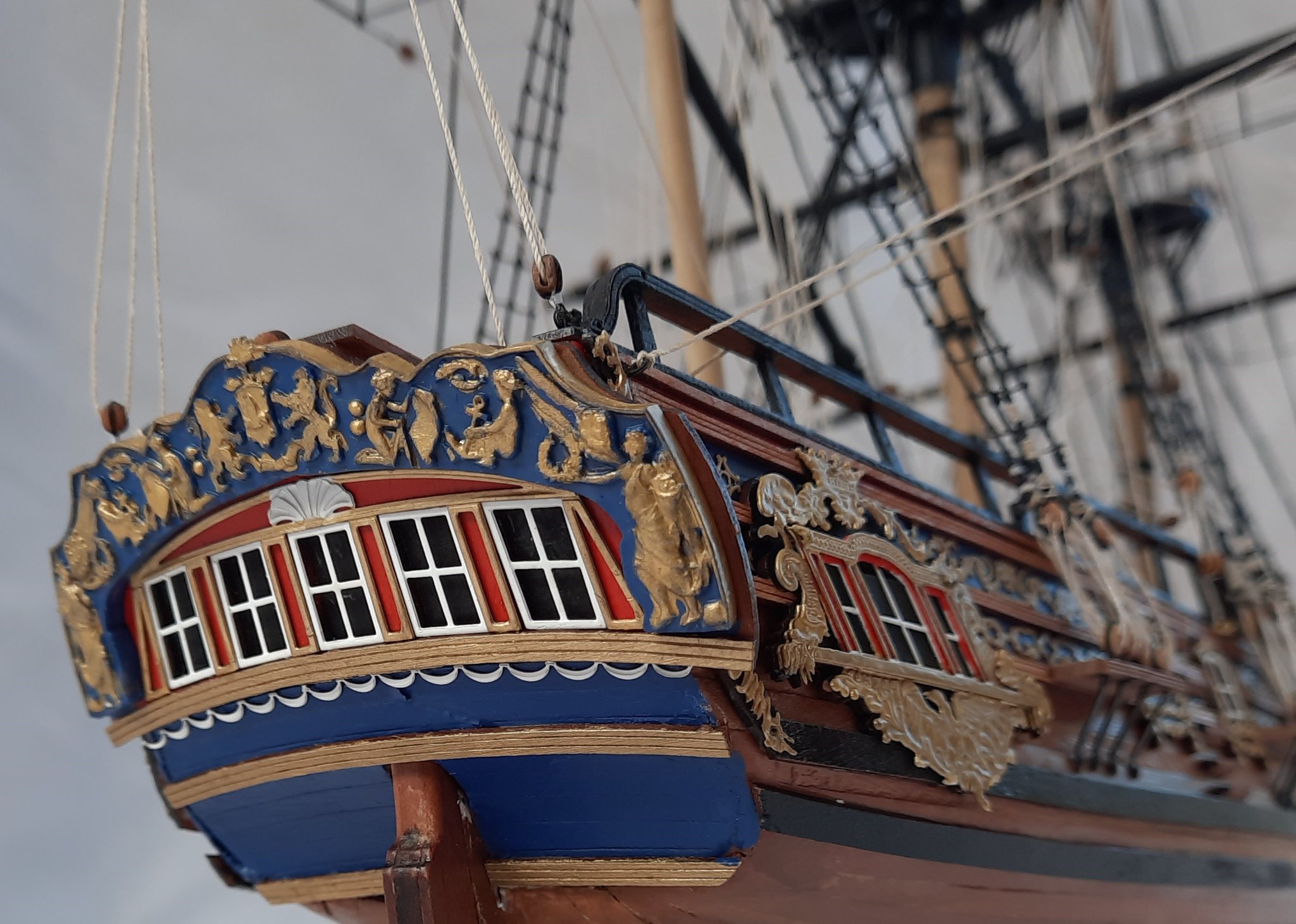
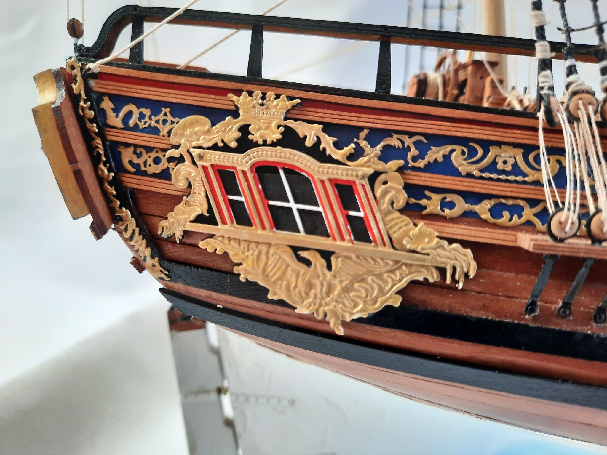
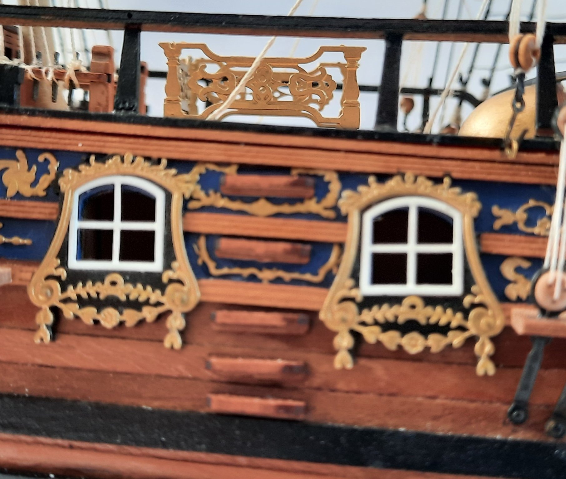
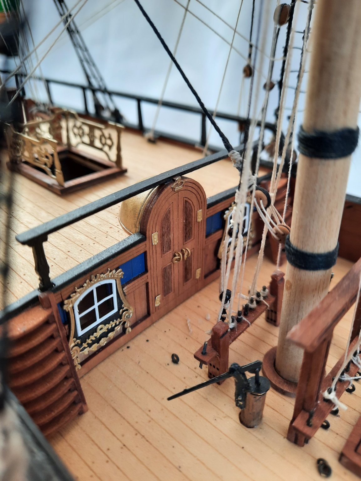
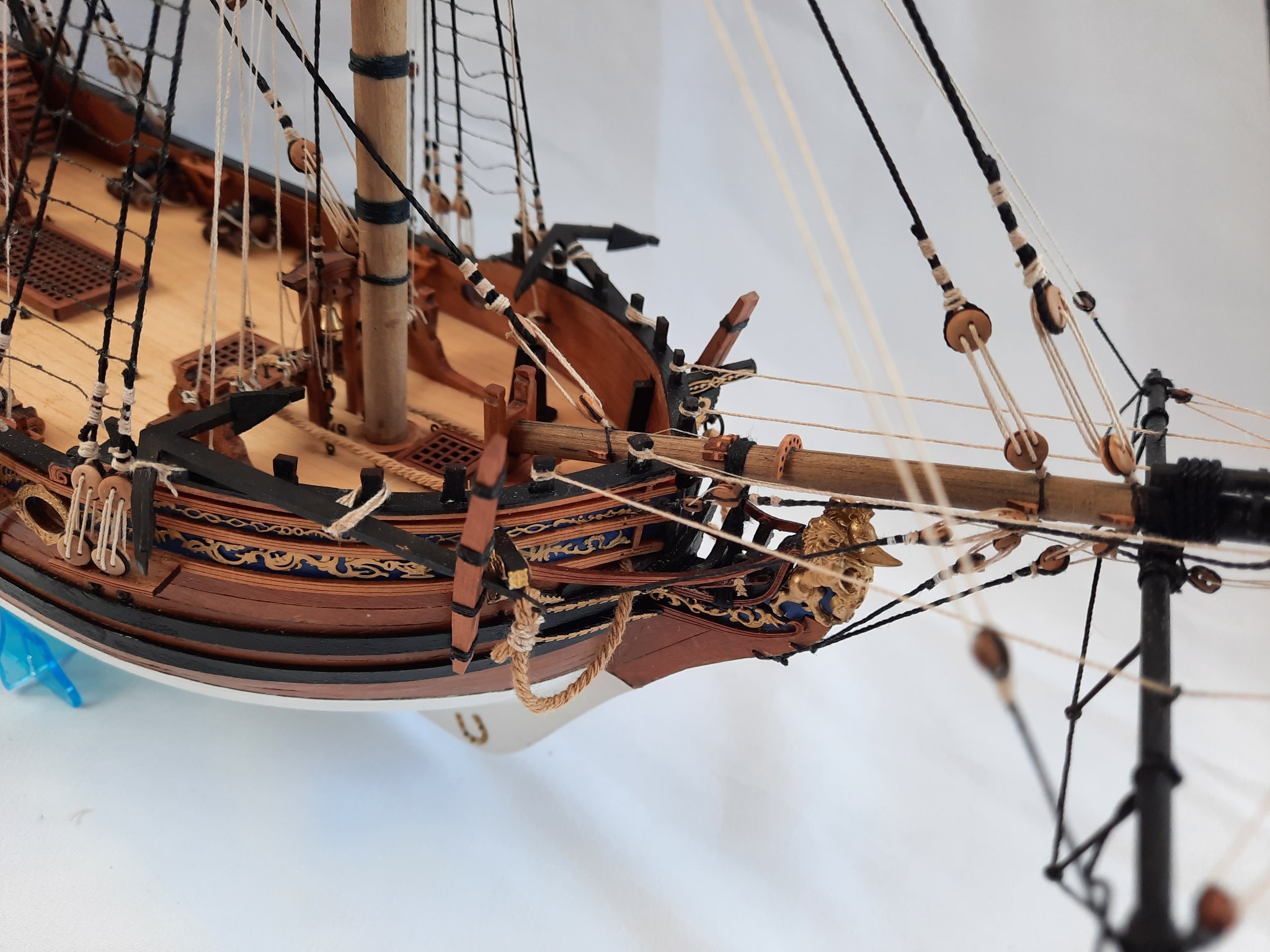
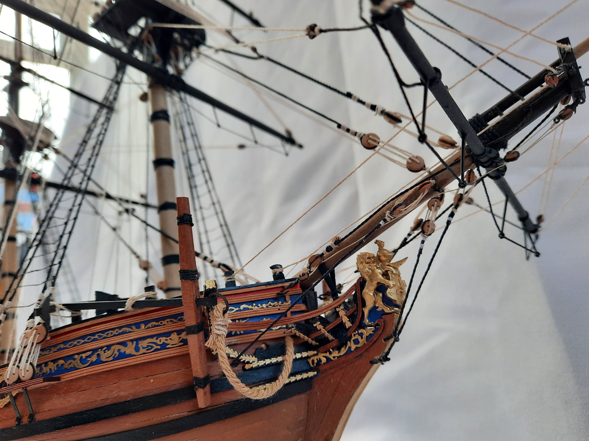
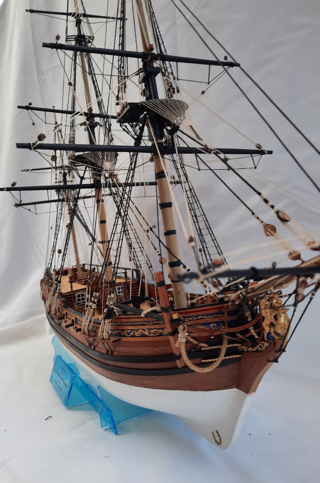
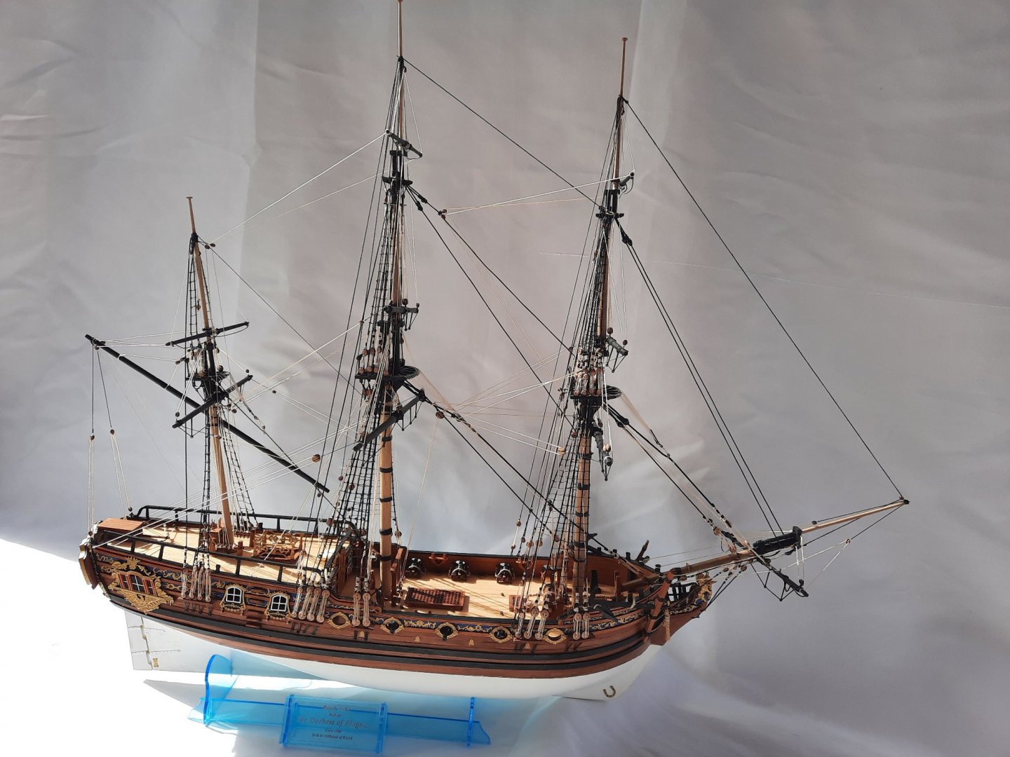
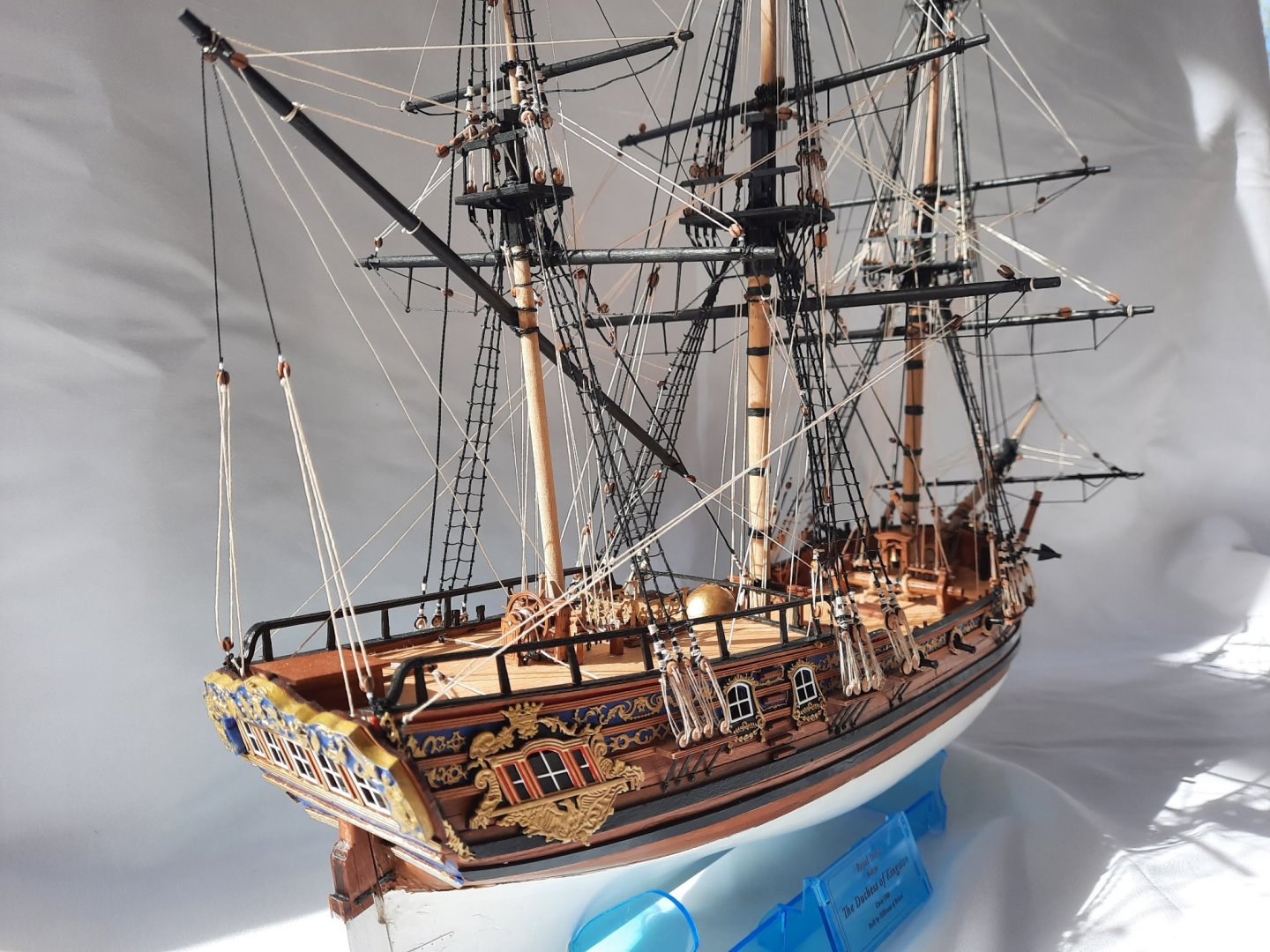
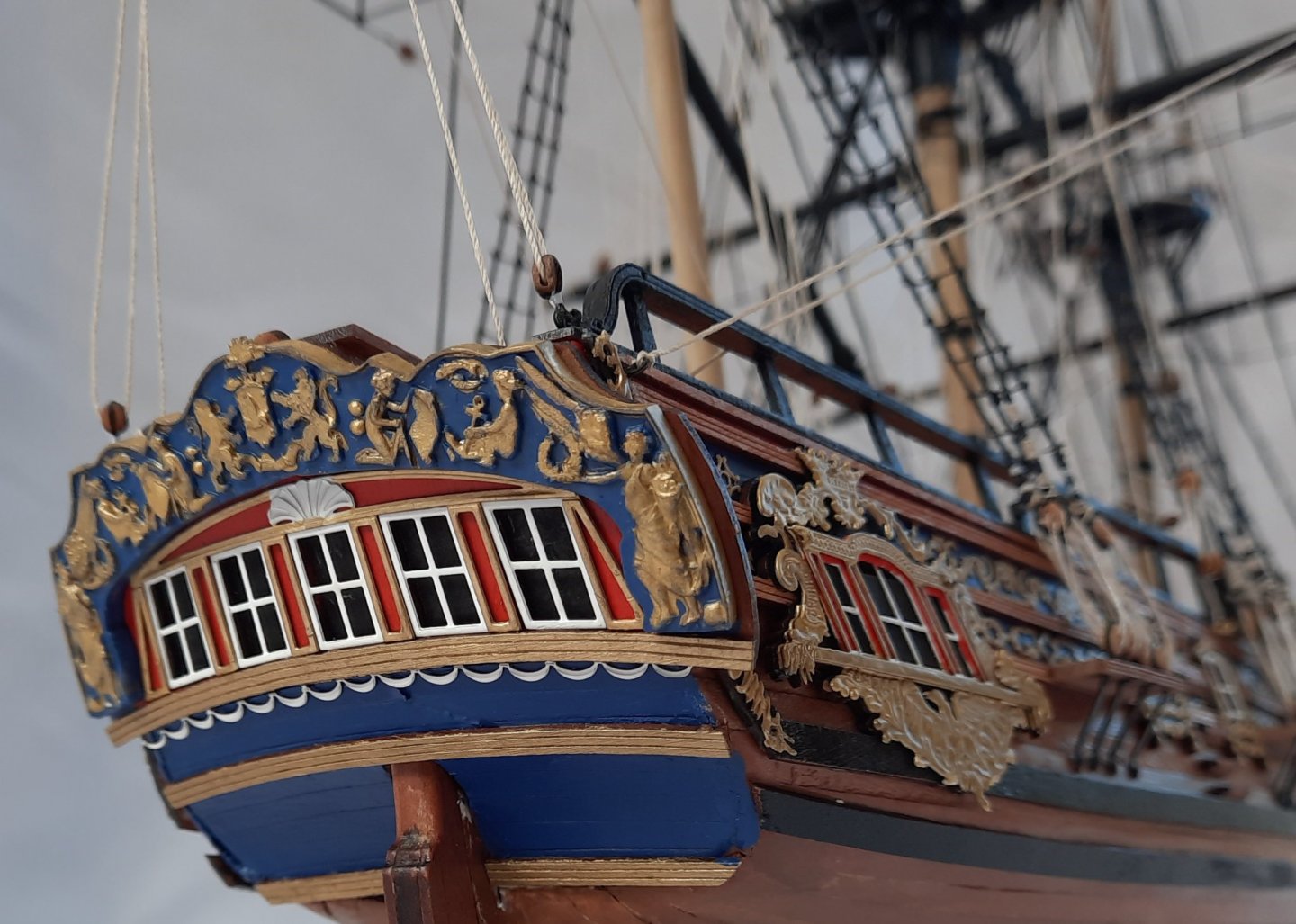
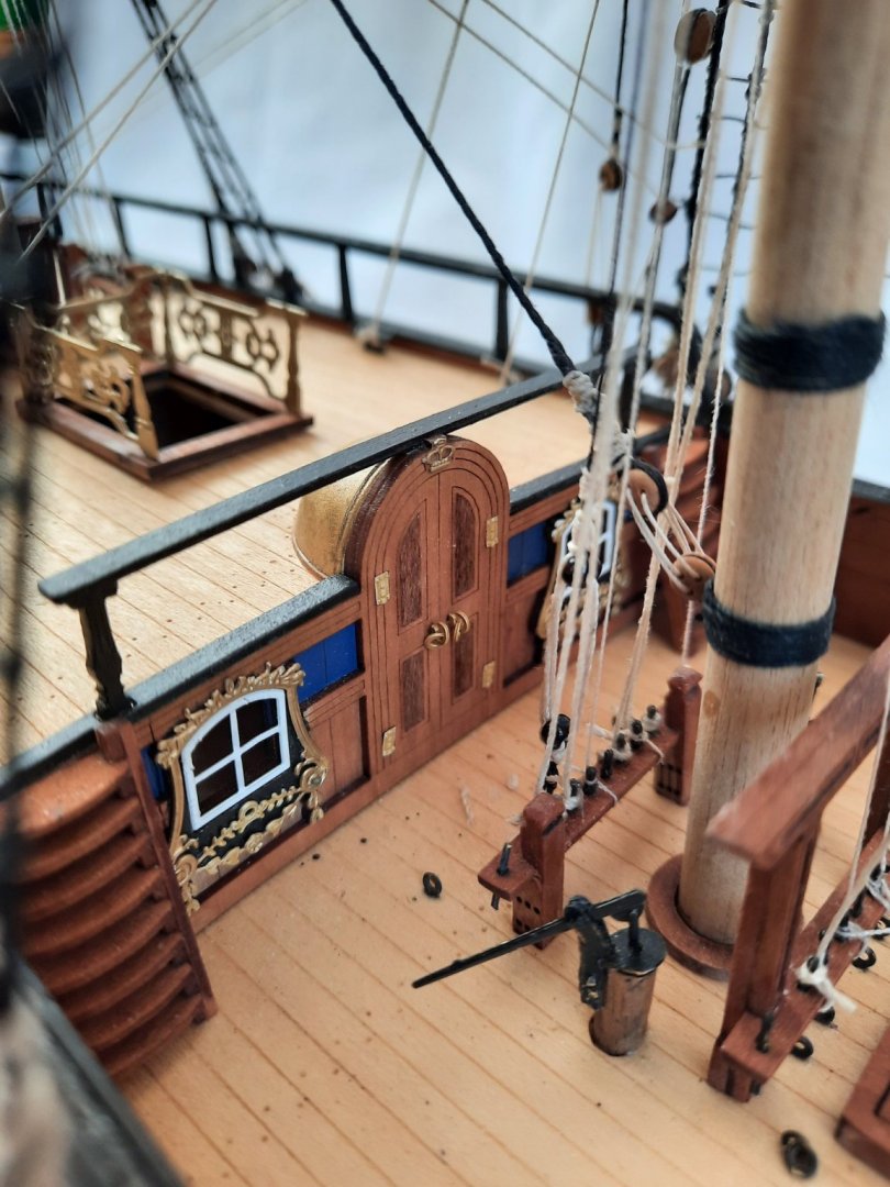
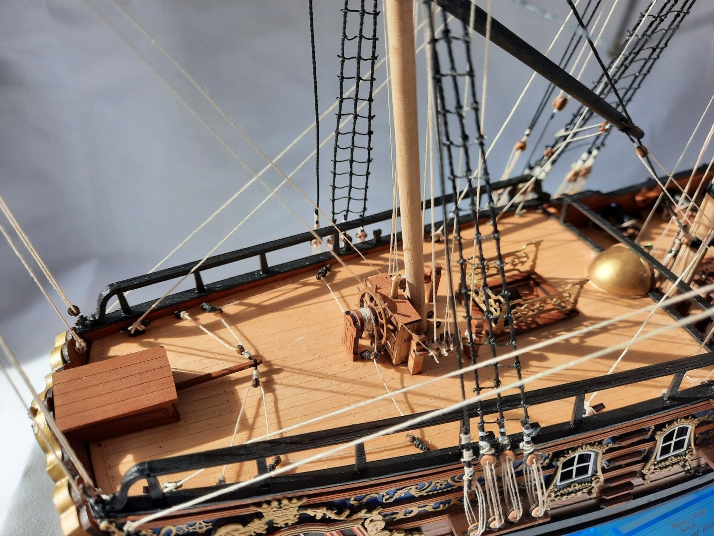
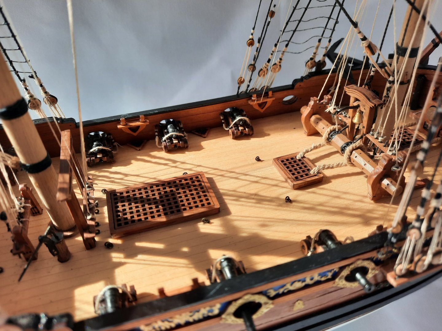
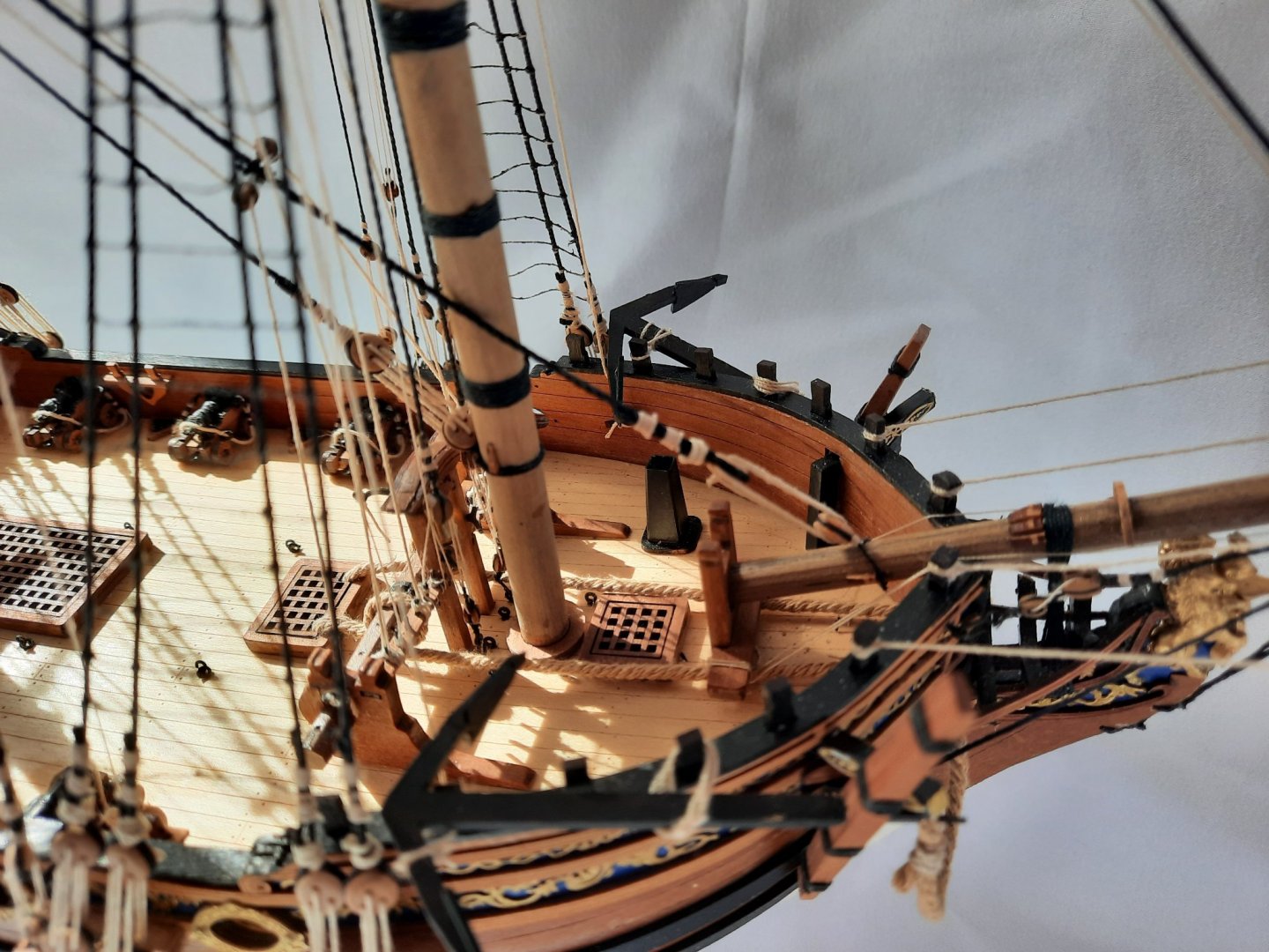
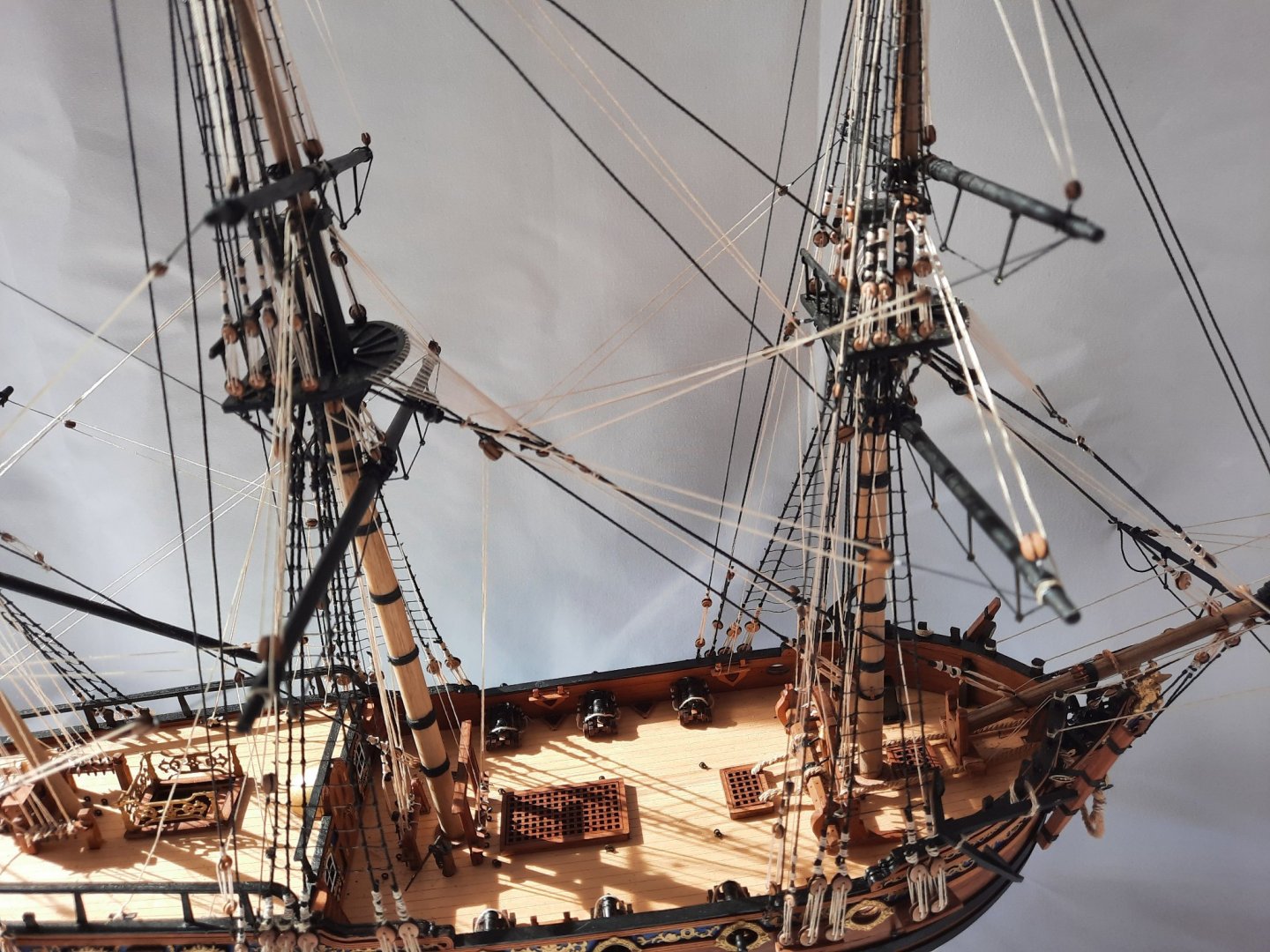
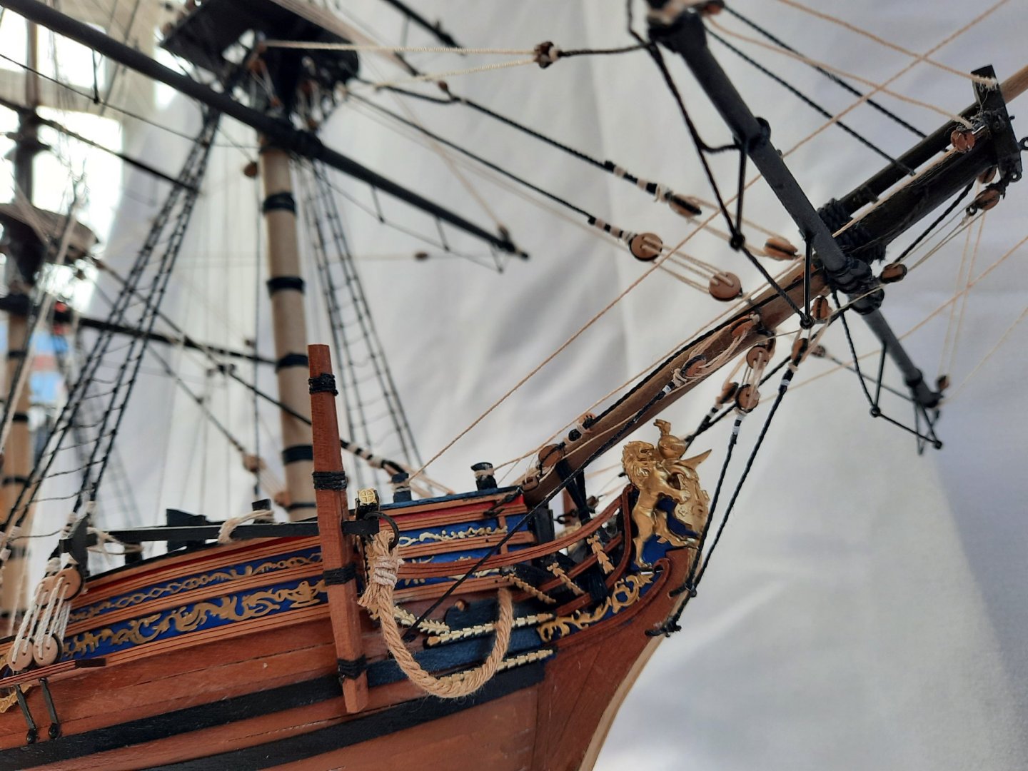
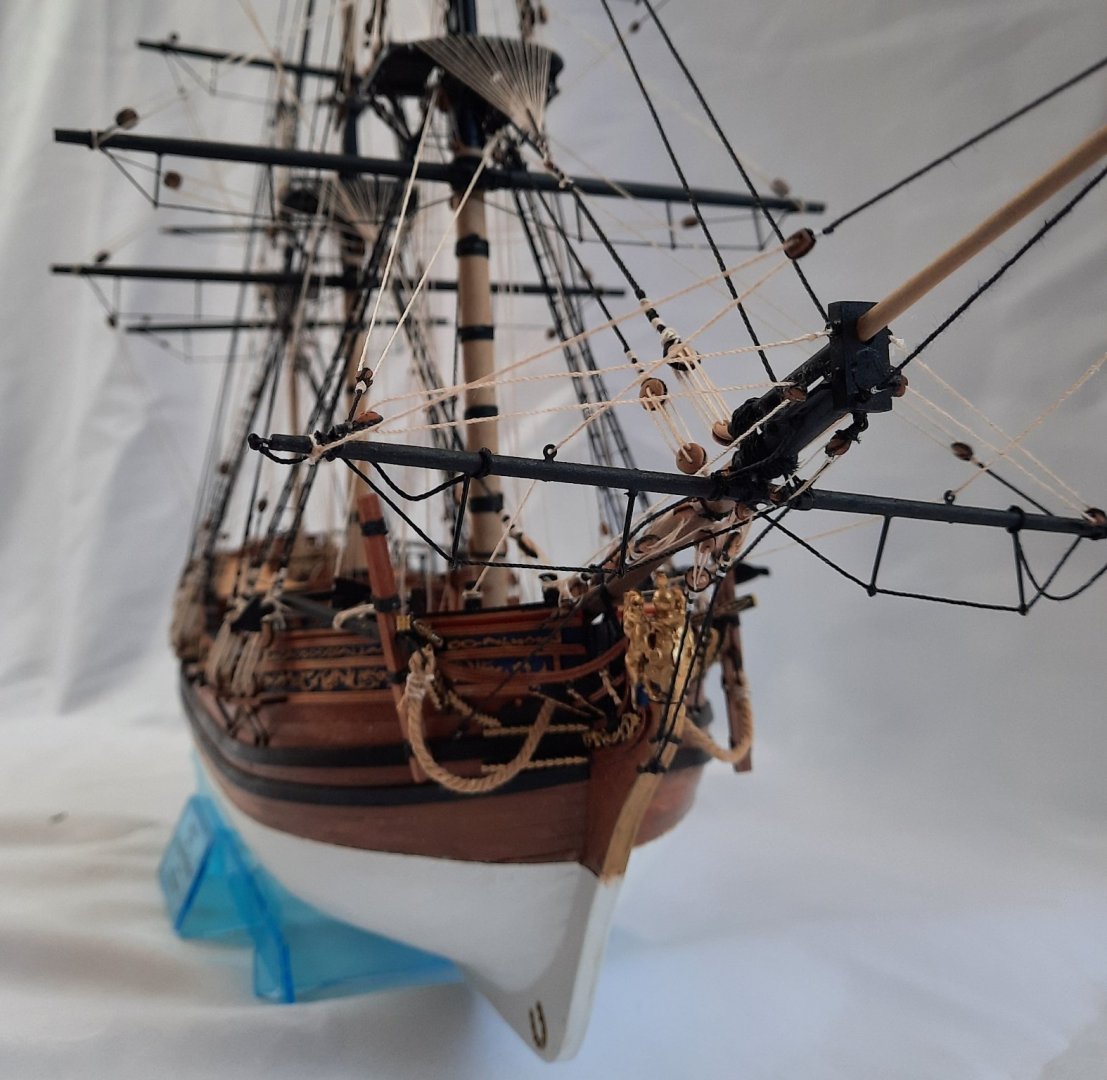
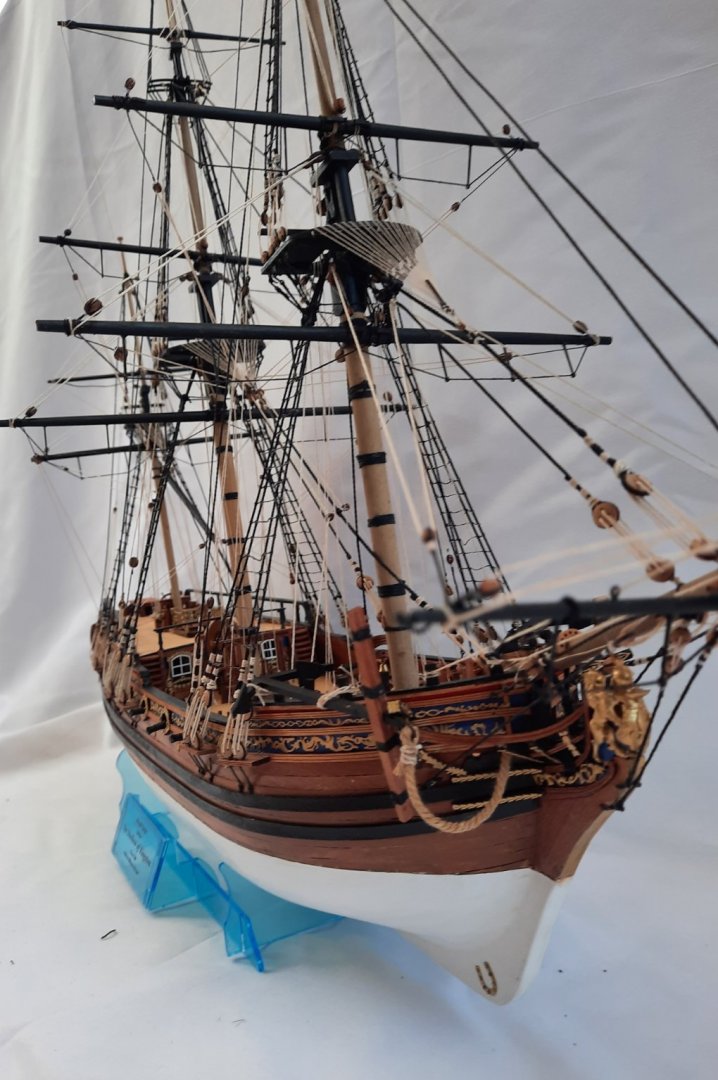
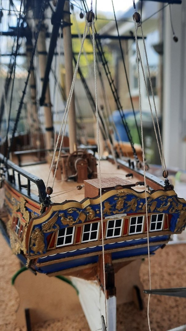
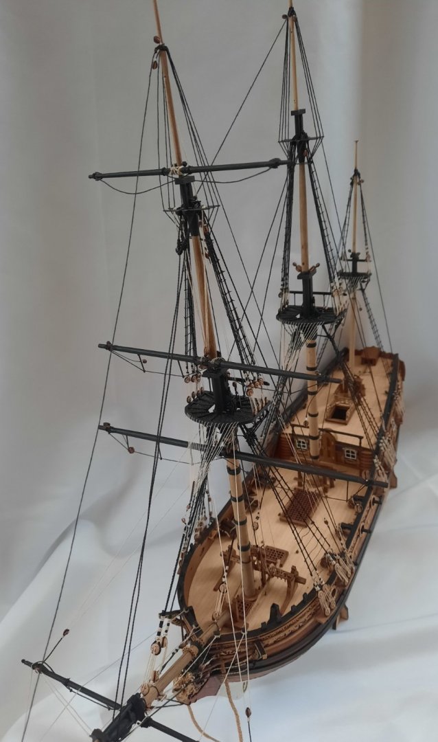
All things must come to an end and today I finally completed my build of The Duchess Of Kingston. This has been a very enjoyable project and many thanks to Chris Watton for an excellent design. I have made plenty of mistakes during the build and it is fair to say that there is still plenty of room for improvement especially with my rigging. I have ordered a display case which will delivered in about 4 weeks time. I have taken a few photos of my completed build. The completed build Another view Stern Windows Main Window More Windows and Steps Cabin Doors Helm Midships Deck Bow Deck Section Figurehead


- 382 replies
-
- 21
-
-
- Vanguard Models
- Duchess of Kingston
- (and 1 more)
-
Wishing your wife a speedy recovery.
-
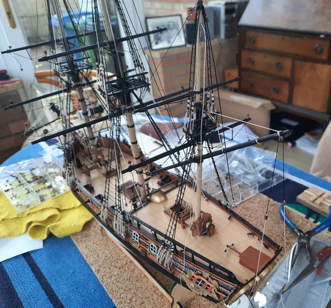
The end of the build is now in sight. Today I finished belaying the yard lifts. It is extremely difficult to belay to the main mast bitts aft belaying rail due to the very limited access. I managed it with a few cheats, mainly using ca gel to hold the thread in place at times. I have also added the fore yard braces, so all that is left is the main mast and mizzen mast yard braces and the anchor.

- 382 replies
-
- 12
-
-
- Vanguard Models
- Duchess of Kingston
- (and 1 more)
-
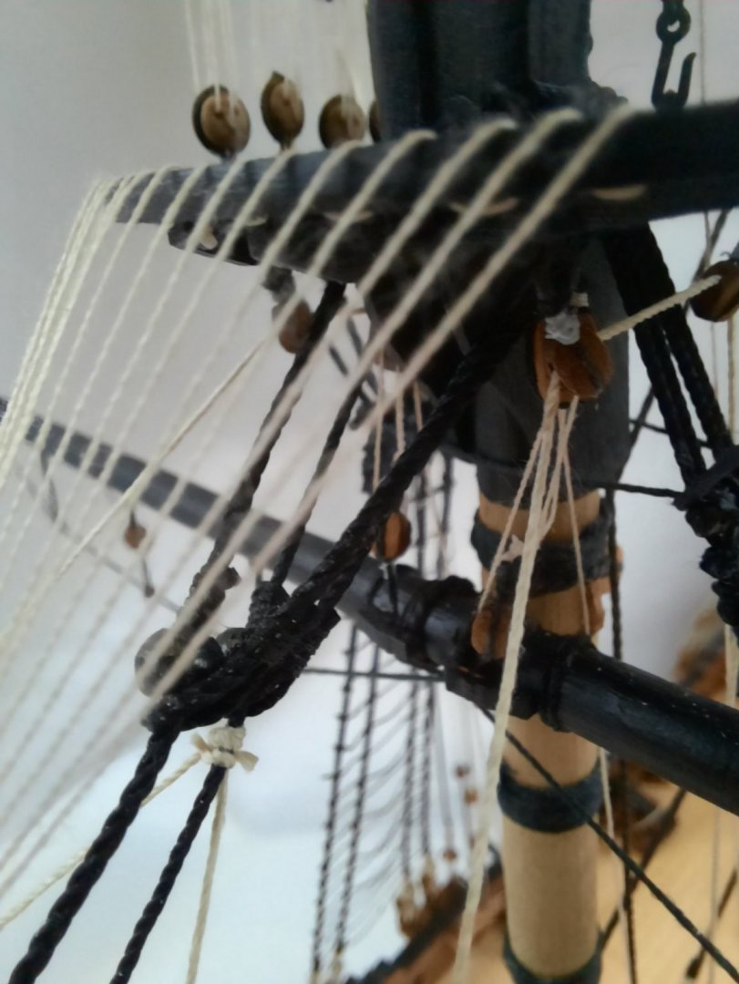
It has been a productive day the ship yard. As indicated in a previous post the seizing on the block at the end of the bowsprit for the fore topgallant stay had failed. My first task this morning was to remove the stay rigging and to refasten the block to the end of the bowsprit. Once this was done I was able to run in a new piece of thread for the fore topgallant stay. Next I moved on to adding the yard lifts. I was surprised how much progress I have made in this respect today. All the fore yard lifts have been fully rigged and belayed. The main yard lifts and the mizzen yard lifts have also been fully rigged but they have not, as yet, been belayed. This is a picture showing the fore yard lifts. When belaying the foreyard I noticed I had failed to fit the two cleats to the inner bulwarks. It was a bit awkward to fit then at this late stage but thankfully I was able to get them glued on place. This next picture shows all the yard lifts, and the un-belayed threads for main and mizzen yards can be seen. They have been threaded down the masts toward their respective belaying pins. It is now simple a matter of a slightly adjusting the tension in each of the lifts when setting the yards square to the masts before the ends are belayed. Once I have belayed the main and mizzen yard lifts, all that is left to do is to add the various yard braces and then to finally to add the anchor. With a fair wind I hope to complete the Duchess of Kingston build within the next couple of weeks. I have also started to look a suitable display case for this model. On one of the most popular quiz shows on TV last week there was a round where the answers all ended with the letters QUE. One of the question was: " A name given to a sailing ship, typically with three masts, in which the foremast and mainmast are square-rigged and the mizzenmast is rigged fore and aft." My wife look at me expectantly waiting for me to show off my depth of knowledge. Sadly I could not offer an answer so she said what about BARQUE as an answer, as she had once heard of a ship called the Bark Endeavour. My humiliation was complete as BARQUE turned out to be the correct answer.
- 382 replies
-
- 11
-

-
-
- Vanguard Models
- Duchess of Kingston
- (and 1 more)
-
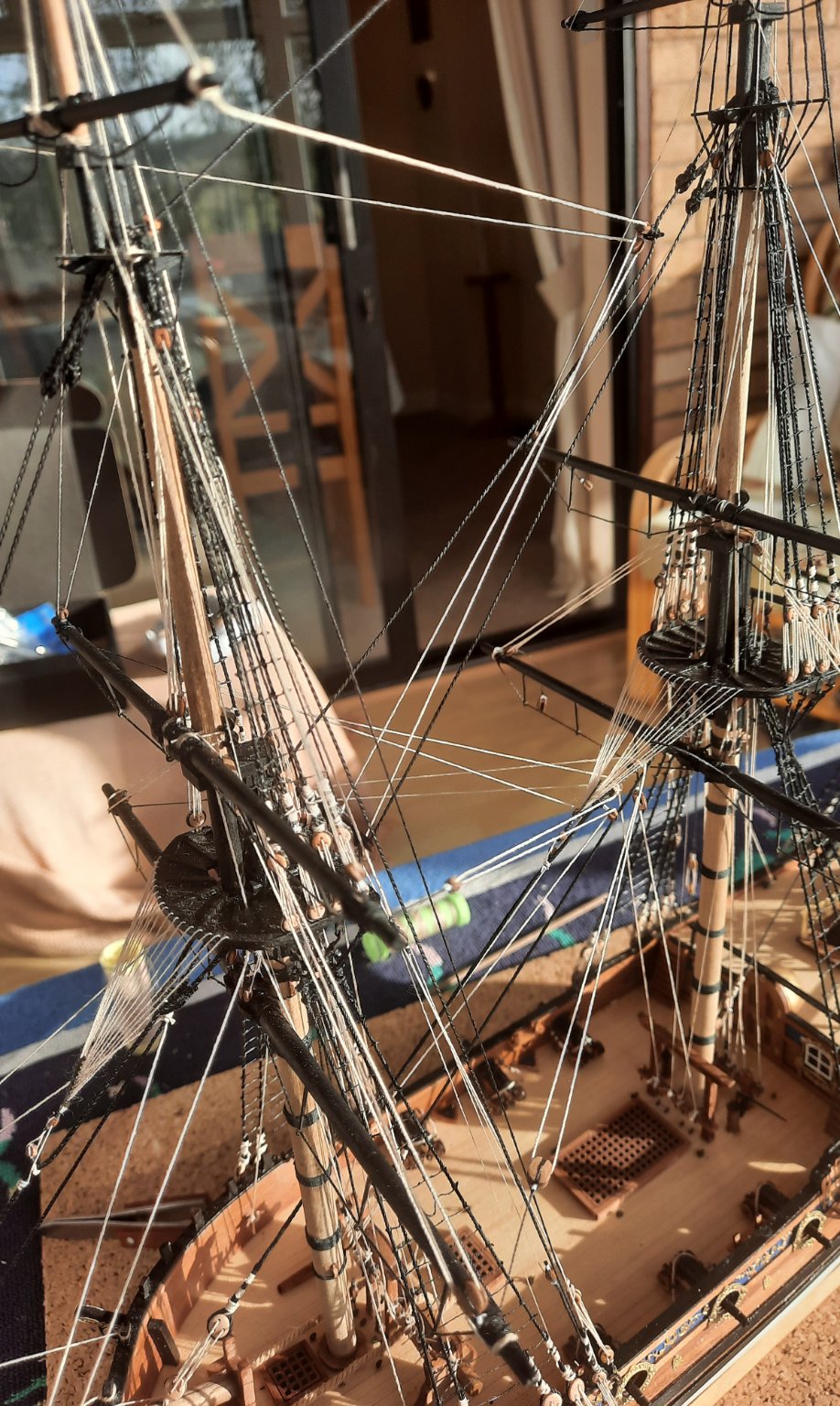
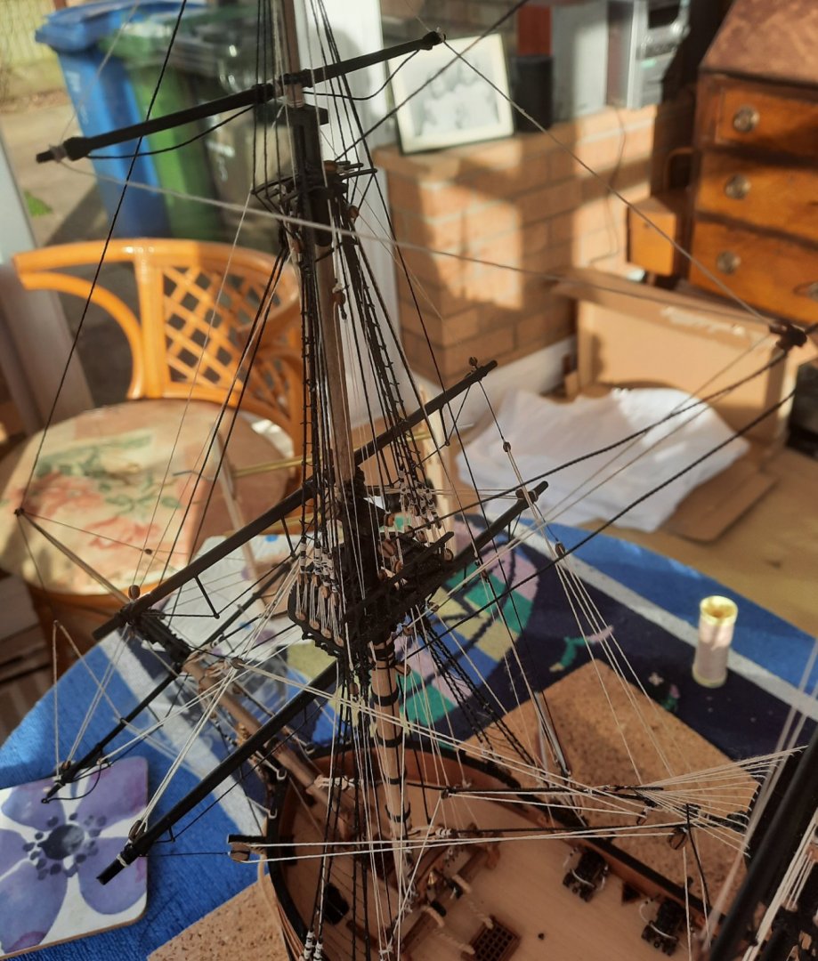
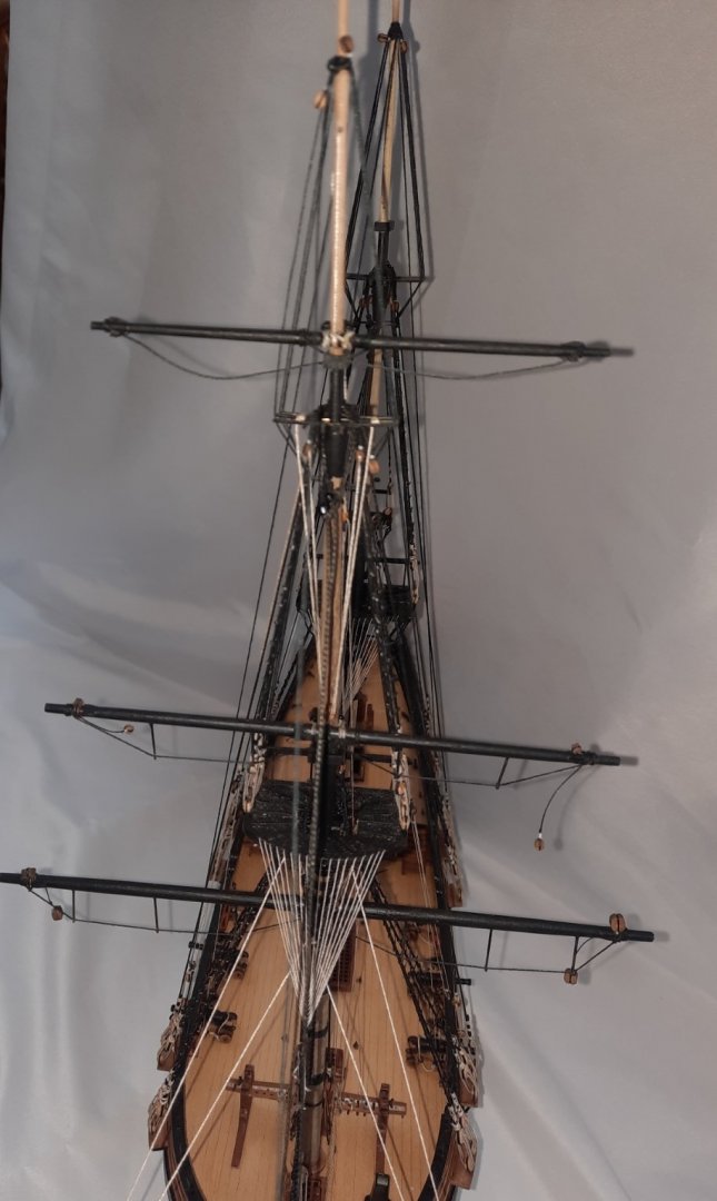
Progress has been a bit slower than expected over the last few days. All the yards have now been secured to the masts as can be seen in the picture below. IJN Yamato and Speedy are in the background. I have almost completed adding the jeers, I only have the mizzen lateen yard and mizzen topsail yard jeers to complete. These jeers have been rigged and just waiting for me to be belay them. In the picture below I was setting the position of the mizzen latten yard and getting the correct tension and position of the central block arrangement. The two tail threads have not been rigged through the blocks at this stage but are held under tension using a couple of reverse action twezzers. In the next picture the two tail threads have now been rigged through the blocks and are now ready to be belayed to their respective cleats.

- 382 replies
-
- 11
-
-
- Vanguard Models
- Duchess of Kingston
- (and 1 more)
-
Thanks Rusty Even when lines seem clear they become magically crossed during the belaying process.
- 382 replies
-
- 1
-
-
- Vanguard Models
- Duchess of Kingston
- (and 1 more)
-
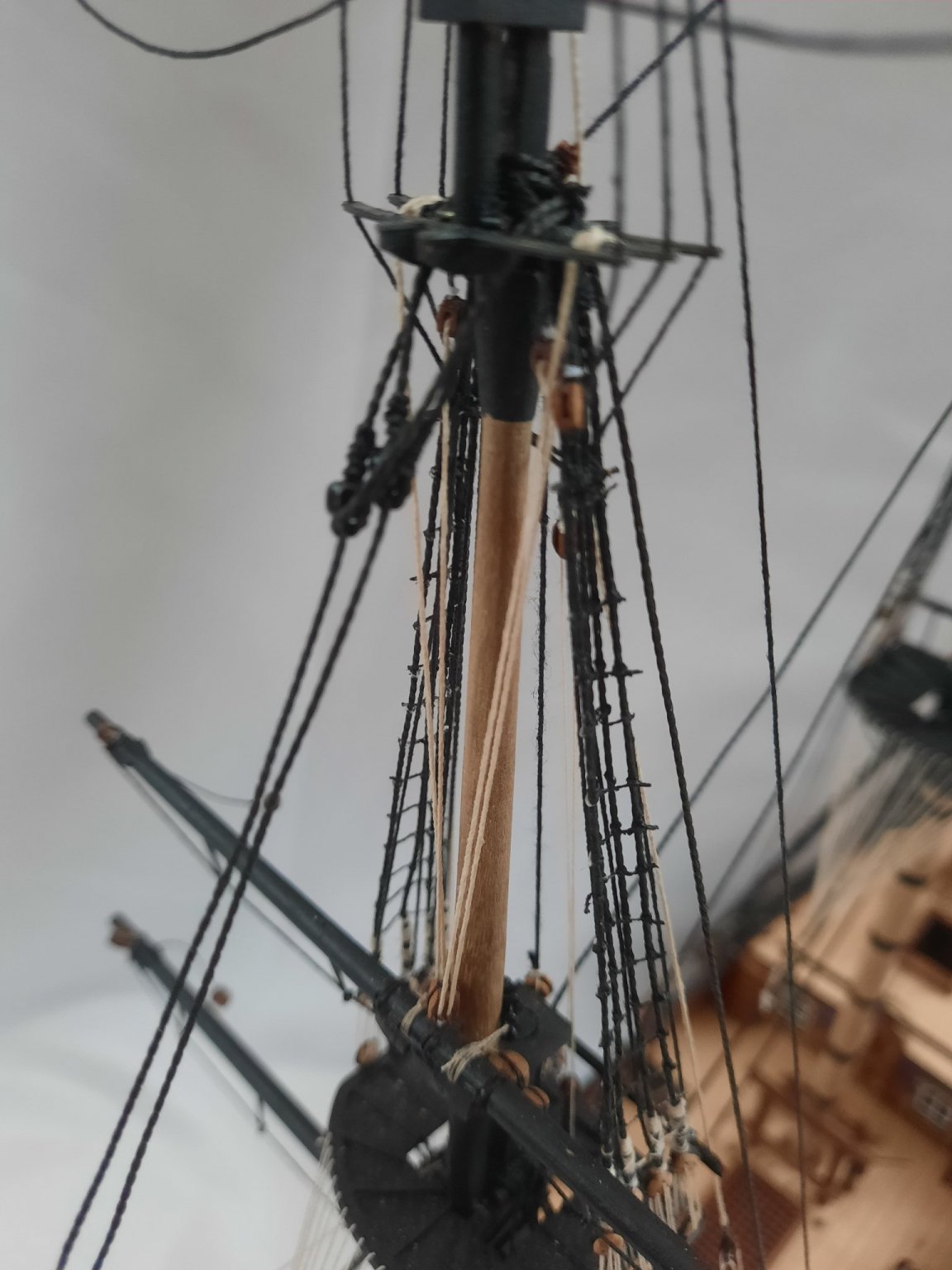
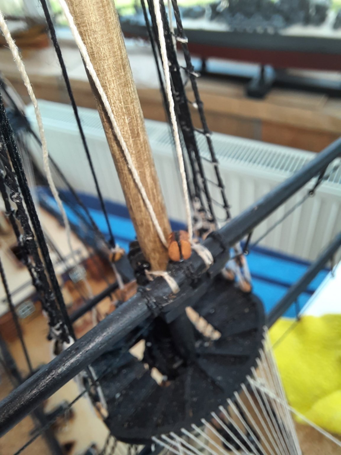
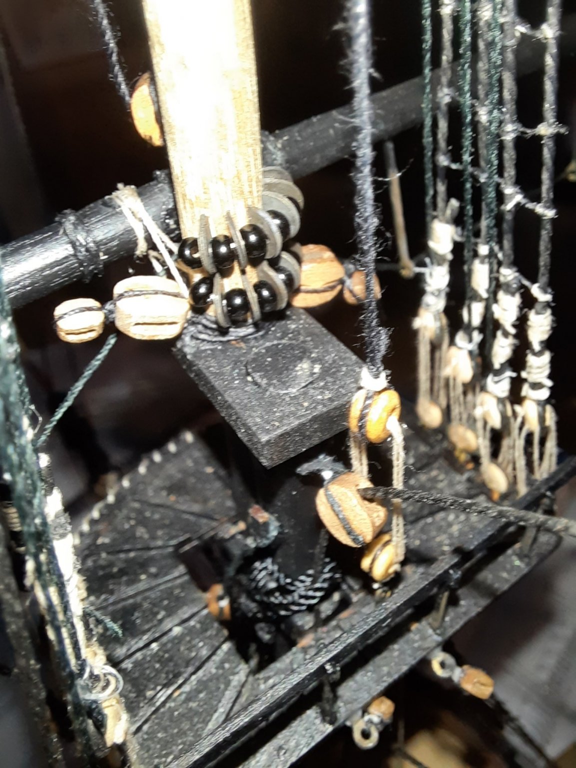
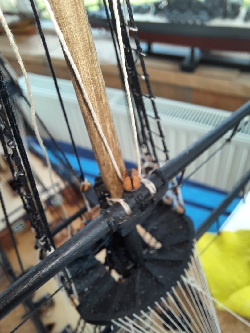
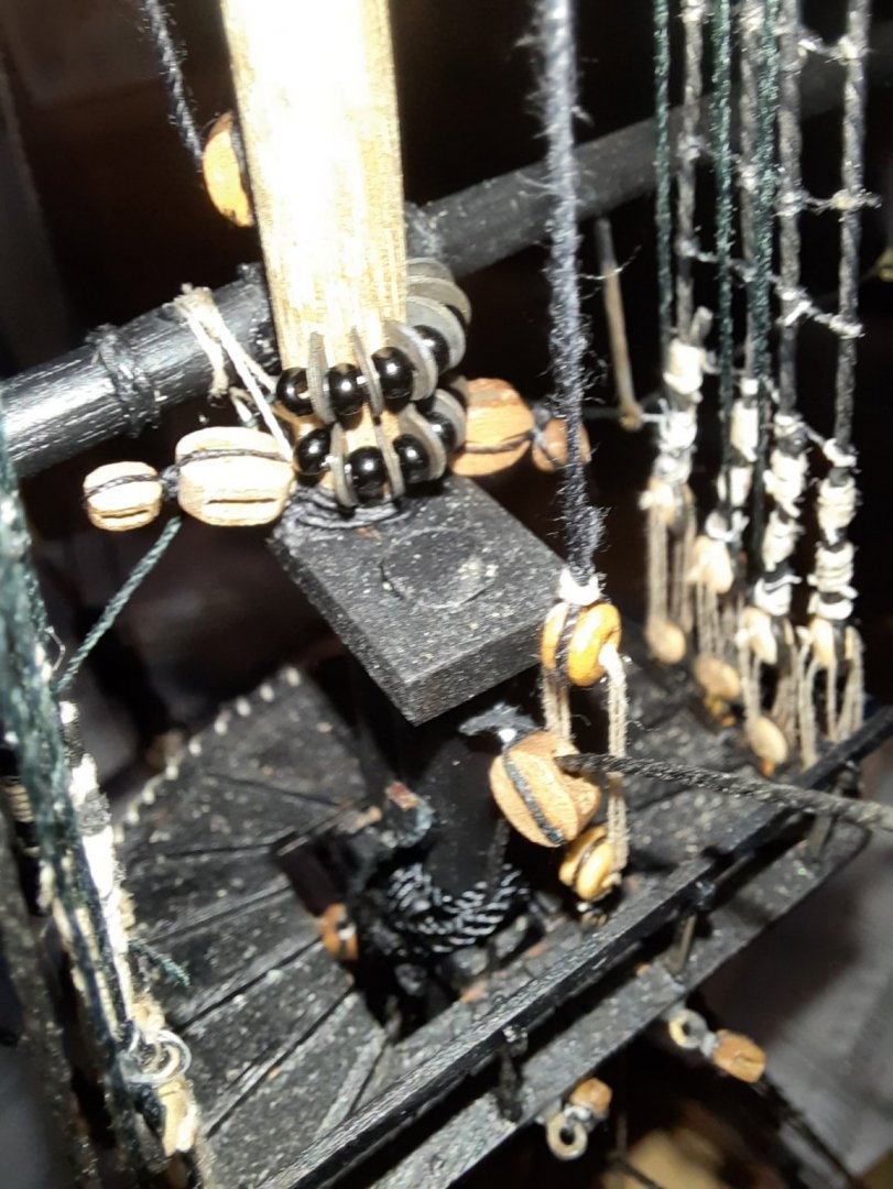
I have now completed securing the yards to the foremast and rigging the jeers. As this work progressed there was a high number of mistakes, many of which have been reworked to fix but some are to remain. I have found this to be a very difficult task to get right. I lost count of the number of times the jeer threads seemed to get wrapped around the various stays. First of here is couple of pictures of the yards in place This picture shows the foreyard jeer blocks This picture shows the fore topmast jeers The parrel beads rigged to the top gallant yard Finally the top gallant yard jeer rigged to the yard and fed through the topgallant mast hole.


- 382 replies
-
- 7
-
-
- Vanguard Models
- Duchess of Kingston
- (and 1 more)
-
Hello Derek The plan does call for 0.5mm natural thread. Thread has now been replaced. Thanks Derek.
- 382 replies
-
- 1
-
-
- Vanguard Models
- Duchess of Kingston
- (and 1 more)
-
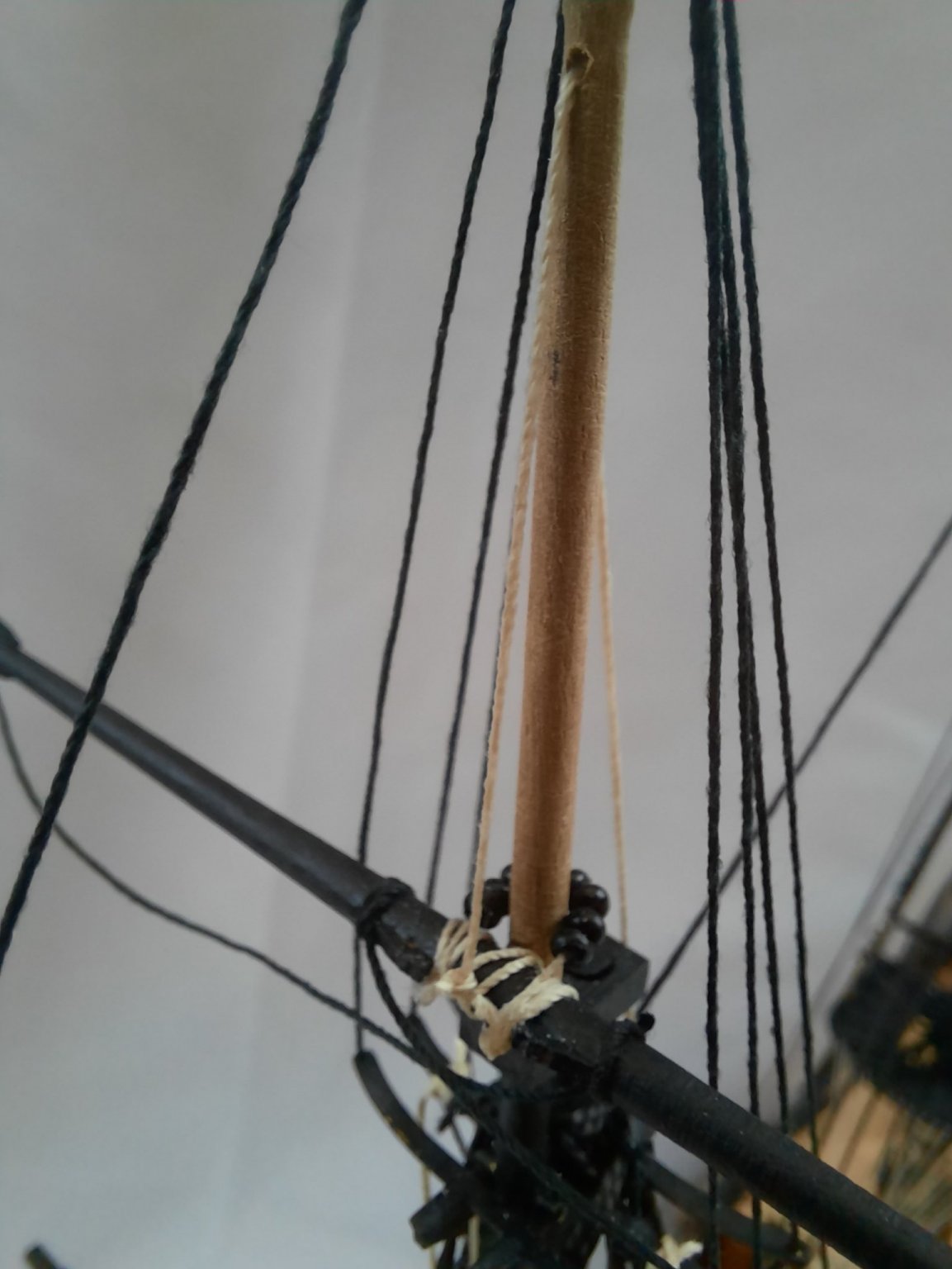
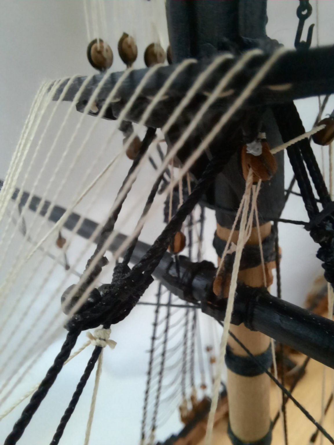
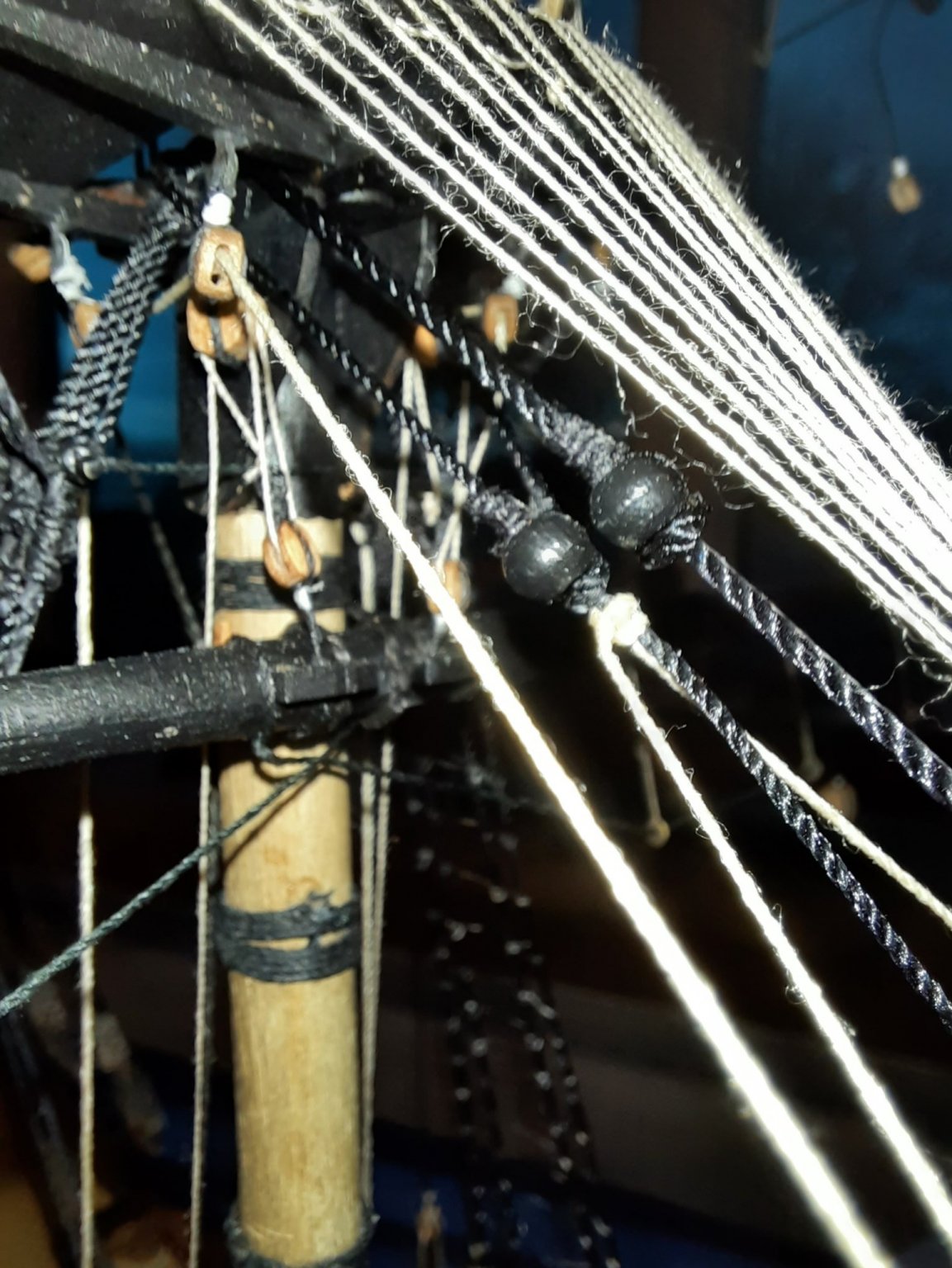
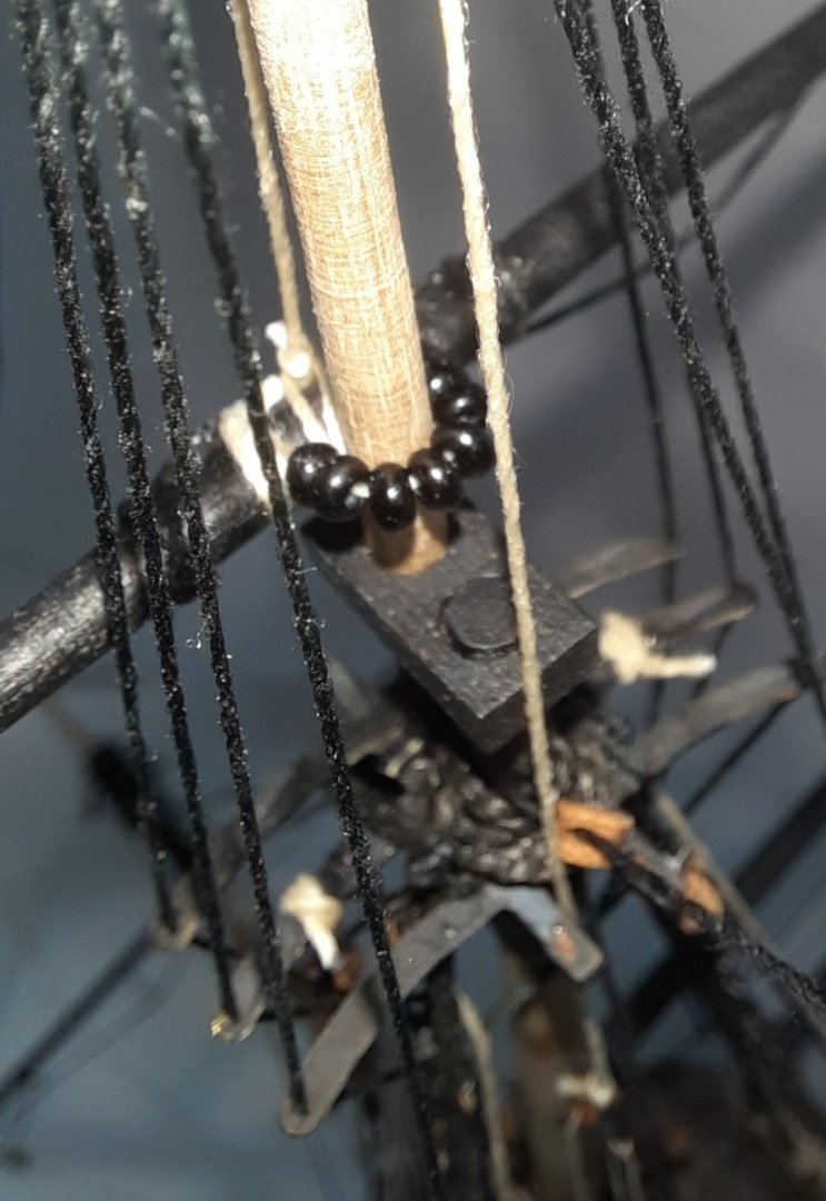
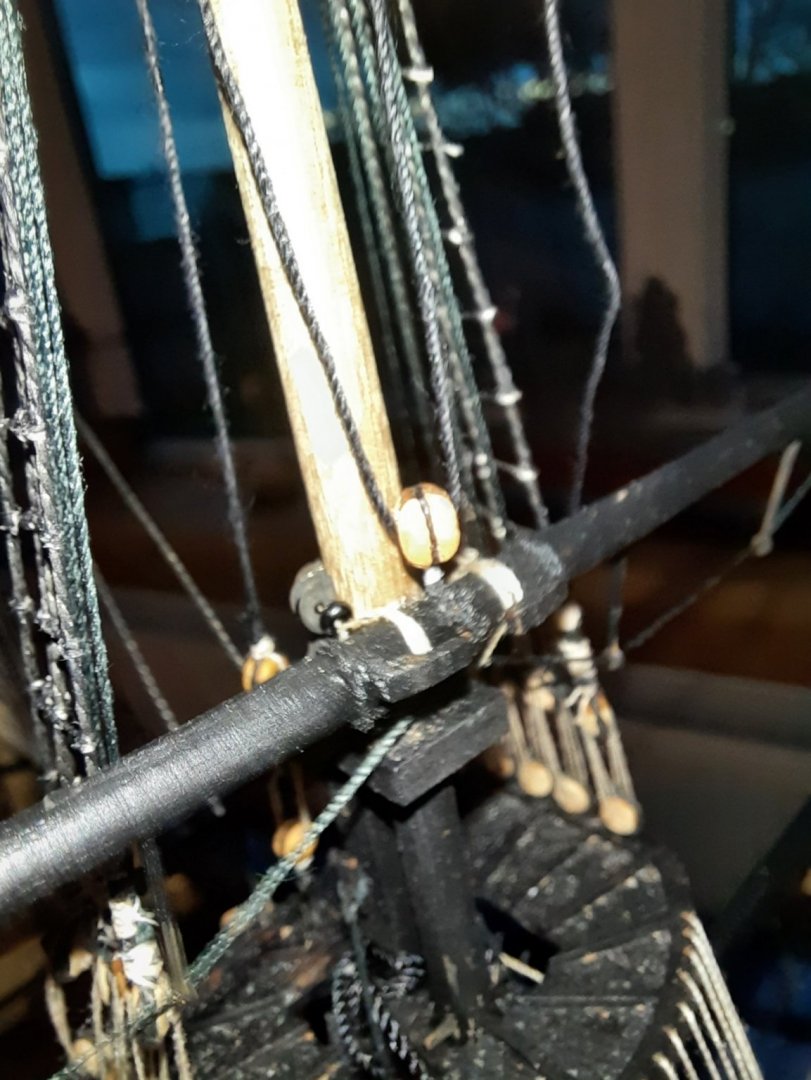
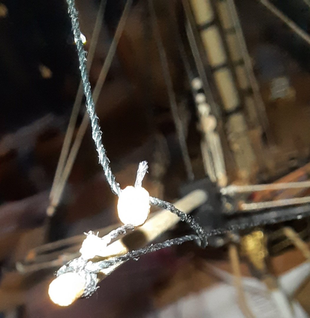
Whilst working on securing the yards to the foremast I noticed the fore topgallant stay had become very slack. On further inspection I discovered the 3mm block at the end of the bowsprit had suffered a seizing failure. Fortunately this will be as simple task to remove the stay rigging and to then replace. Picture of the failed block seizing failure, there must be a touch of ca still holding the block in place. Work on securing the yards to the masts and rigging the jeers is very slow going at the moment. I have been learning from the errors made and refining my methods as I work on the foremast yards. Hopefully adding the the main and mizzen mast yards will be smoother and quicker. The fore yard has two jeers, each jeer arrangement comprising a 4mm double block and a 3mm single block. Each jeer rigging thread is secured to the loop at the end of the yard 3mm block before being fed through the first hole on the 4mm double block and then fed back through the 3mm single block, back through the other hole on the 4mm double block and belayed on the deck. This is a picture of the fore yard which shows one of the two jeer block arrangement. I found this particularly difficult to rig, but with a little patience and perseverance I eventually managed to complete the task. I did find adding the truck and ribs when securing the fore top yard to the fore mast very frustrating initially. On my first attempt all the truck beads and ribs dropped off both threads. I did let out a shout in annoyance at my poor workmanship skills and my wife came through to see if I was OK as she thought I had hurt myself. The second attempt was much better and I was able to install without too many issues. Yes I did forget to fit the final rib but I am not going to redo the work as I do not think it will be noticed when the DOK is fully rigged. Adding the fore top mast jeers is still work in progress. There are two threads required. Each thread is tied to either side of the top mast middle crosstree and they are then fed through the 4mm double block on the yard. They are then fed up back up the other side and each are fed through a 3mm single block. Each free end is then secured to a loop at the end of a 2 x 3mm block assembly which is allows the jeer to be belayed in two places, via a hook and pin arrangement. In the picture below the first 0.5mm black thread has been rigged through the double 4mm jeer block and associated 3mm single block and the free end is ready to be belayed to the deck. The other jeer rigging thread will be added in the morning.

- 382 replies
-
- 5
-
-
- Vanguard Models
- Duchess of Kingston
- (and 1 more)
-
Looking great
-
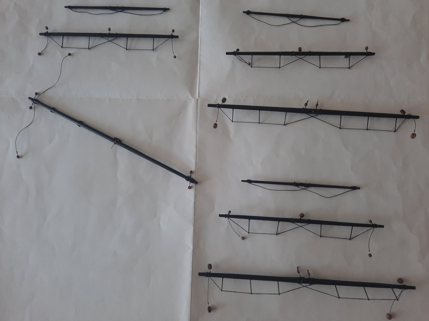
A good couple of days work in the shipyard where I have added all the blocks and stirrups to various yards. It seemed a never ending task of seizing blocks and then securing them to the yards. All the yards have now been painted black and they are ready to be be rigged. The fore yard has been tied in place and I'm currently in the process of rigging the two jeers which is proving to be very fiddley. On a side note there has been an addition to the shipyard with a gift from my sister in law. The boat shape planter was made by a local craftsman and will look resplendent once it has been filled with some hanging basket bedding plants in the next few weeks.
- 382 replies
-
- 9
-
-
- Vanguard Models
- Duchess of Kingston
- (and 1 more)
-
She is really coming together now, you are doing an amazing build.
- 725 replies
-
- 1
-
-
- vanguard models
- speedy
- (and 1 more)
-
Thanks Derek My original Speedy build is dead in the water as I made far to many mistakes. It was a fun build and I learnt so much about building these models. I might build a new Speedy at some stage depending on what new designs Chris comes up with. My next two projects will be the Cutter Alert and then the Sphinx.
-
Thanks, I hope to start rigging the yards in the next couple of days
-
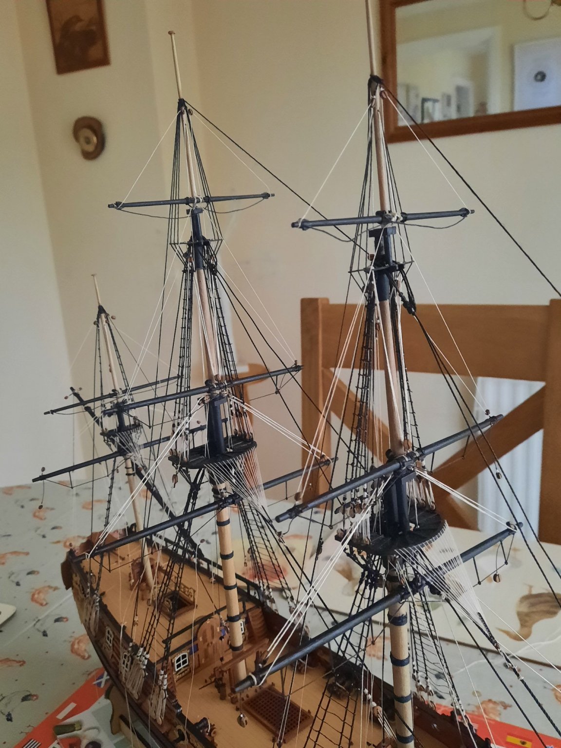
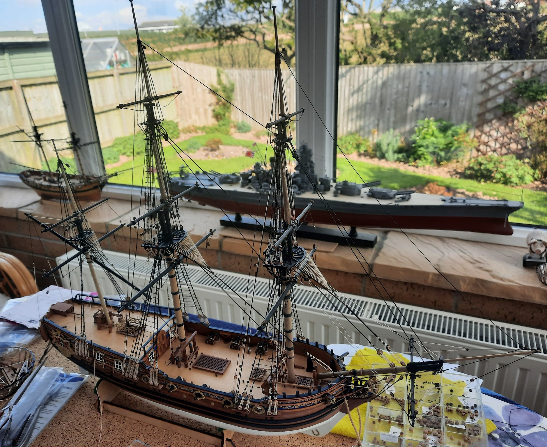
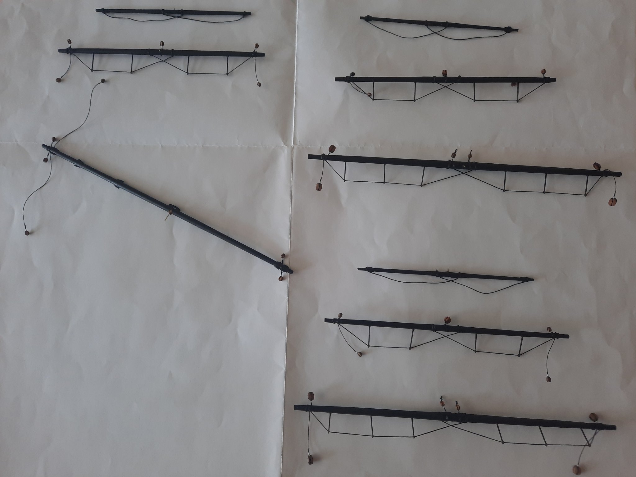
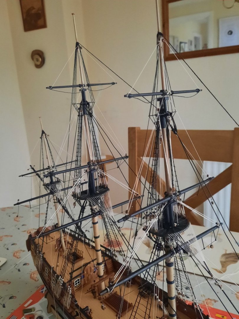
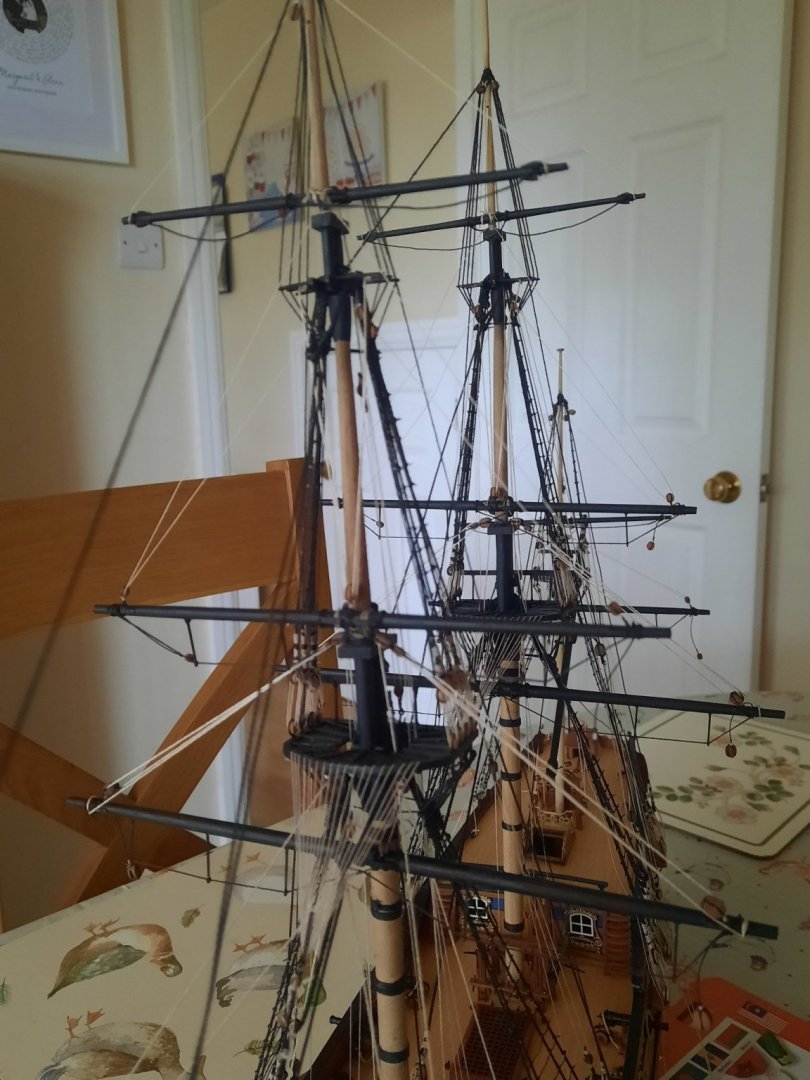
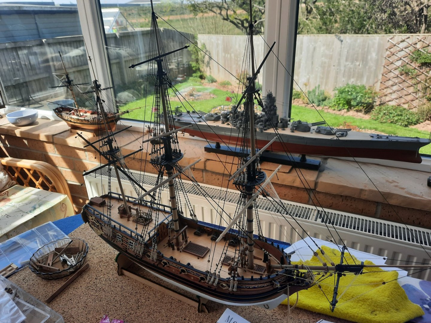
Work has progress well on the manufacture of the various yards. All the mizzen mast yards are fully complete and are now ready for rigging. The main and foremast yards are made and they are now ready for the blocks to be added and then will be painted black, noting I have already painted the two topgallant yards. I have also added a pin to each yard so I could dry fitted them to the masts. This gives me a an idea of how the Duchess Of Kingston will look when fully rigged, it looks very impressive. I have attached a picture, noting the yards are only pinned so they are a bit wonky, especially the fore top gallant yard. I do really like how the Duchess Of Kingston now looks. My completed IJN Yamato model can be seen in the background as is my partially built Speedy which I had to abandon due to my many errors in the rigging.
- 382 replies
-
- 6
-
-
- Vanguard Models
- Duchess of Kingston
- (and 1 more)
-
Hello John Many thanks for you kind comments. Glenn