Glenn-UK
-
Posts
3,169 -
Joined
-
Last visited
Content Type
Profiles
Forums
Gallery
Events
Everything posted by Glenn-UK
-
 Thanks Bob, I took my time with the 1st planking and it really helped to get a great result. I did find it much better to fit the first 6 planks from bulwarks downward and then to work upward from the false keel with the remaining planks. But I'm sure you will find a method that works best for you.
- 382 replies
-
- 2
-

-
- Vanguard Models
- Duchess of Kingston
- (and 1 more)
-
NIce looking build
-
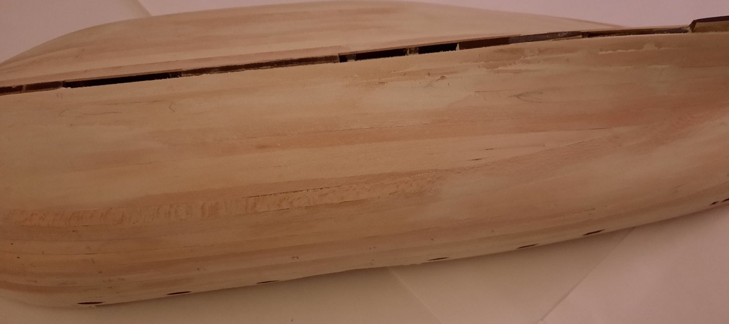
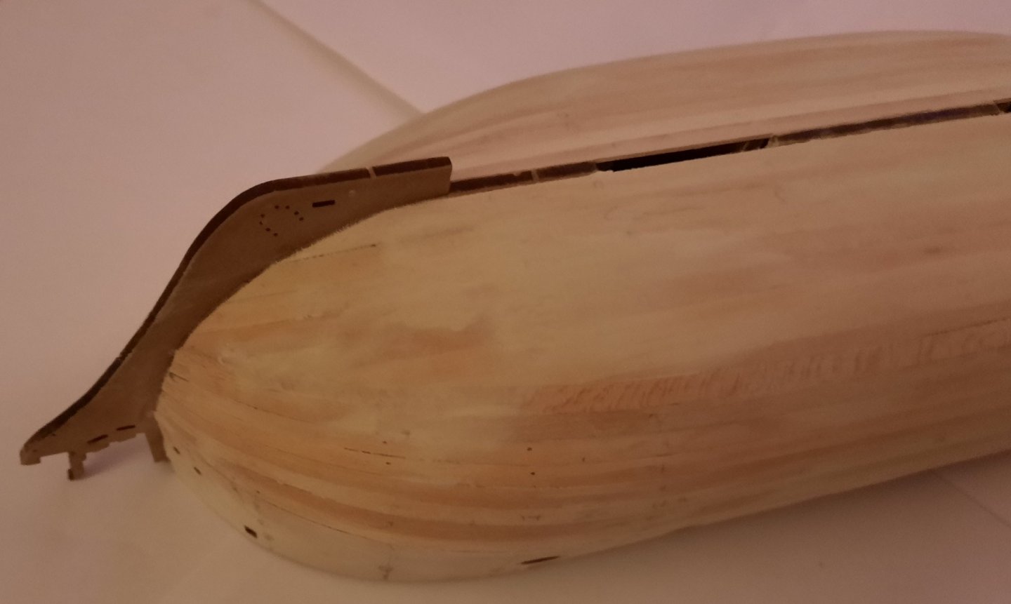
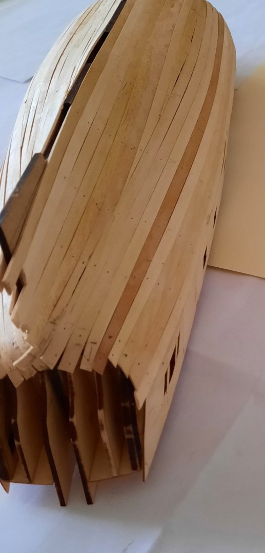
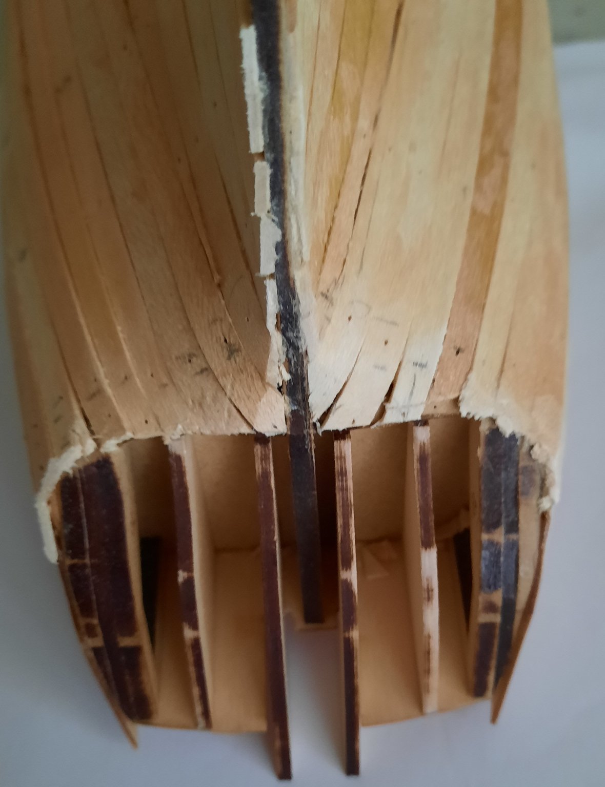
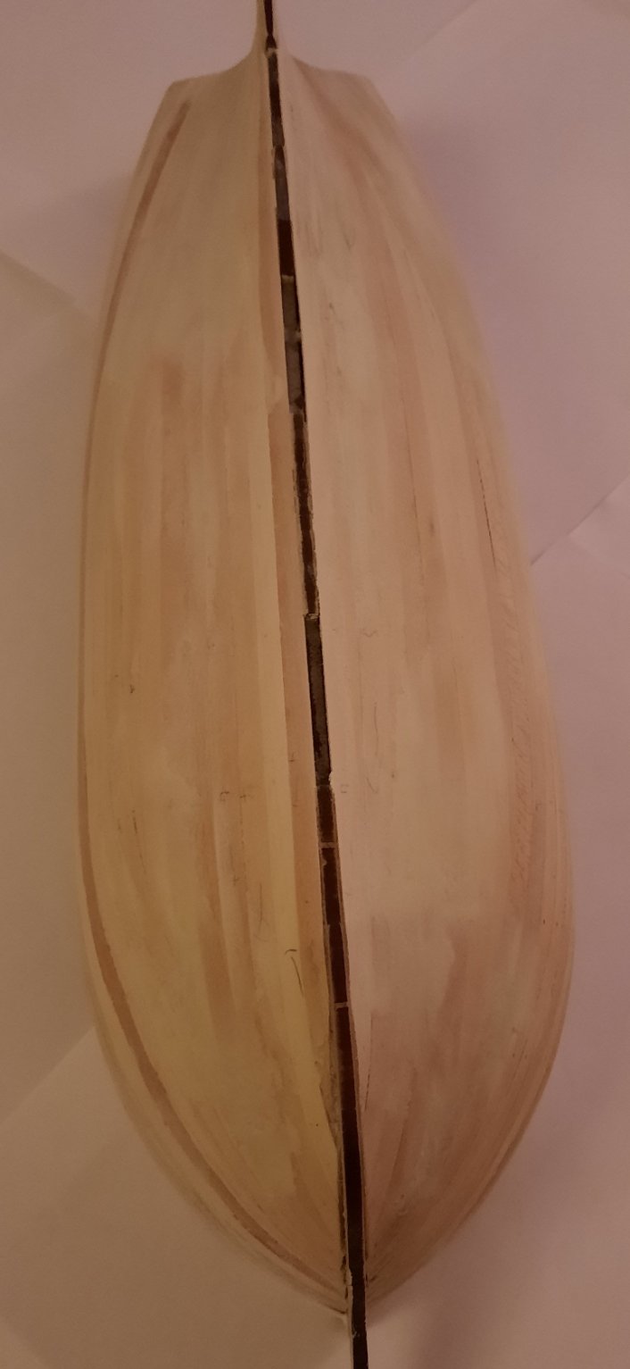
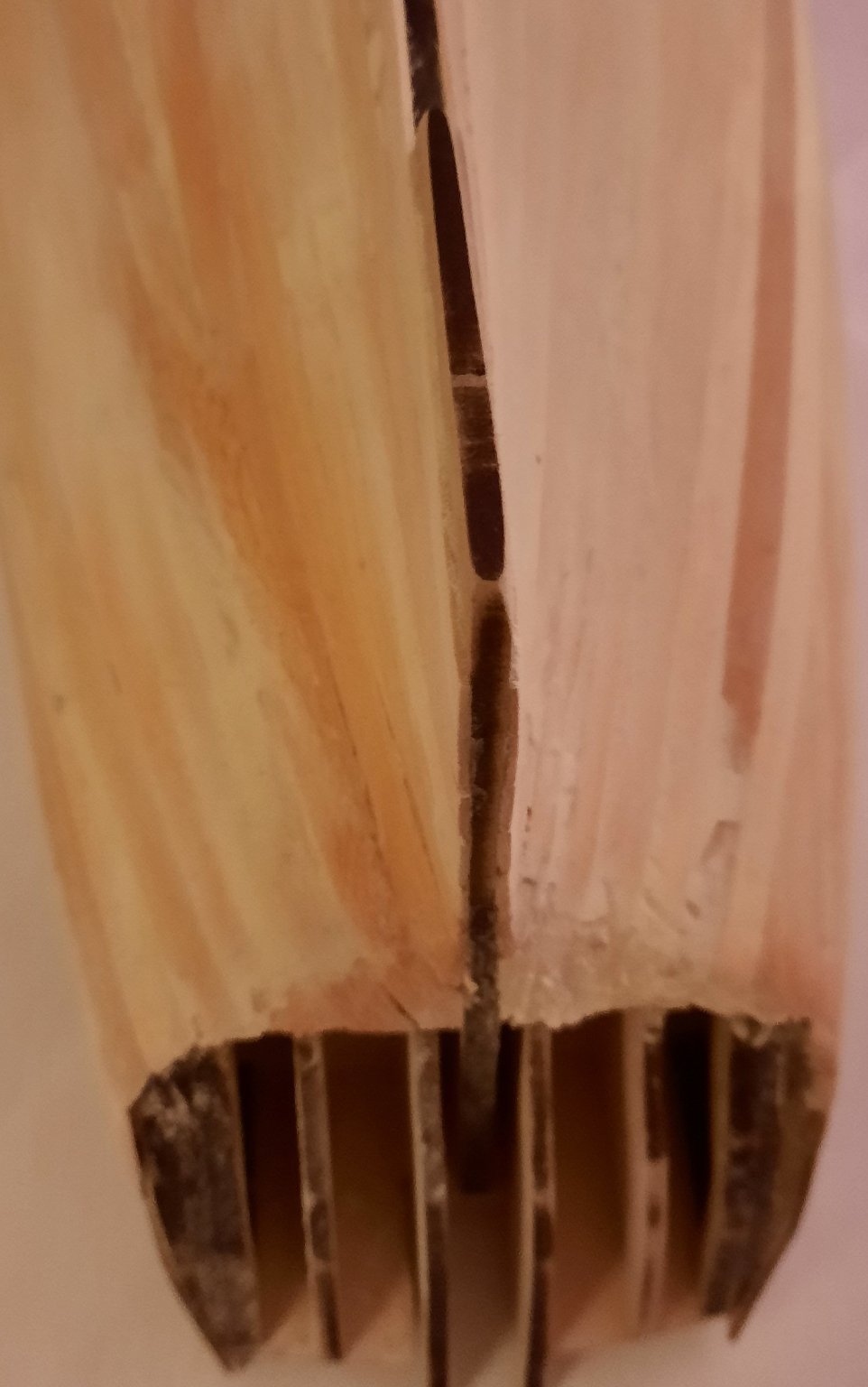
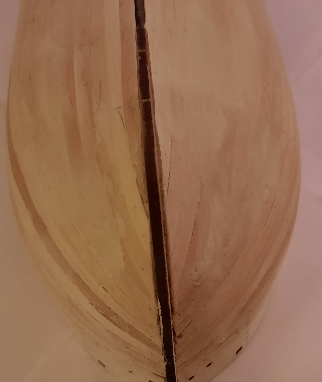
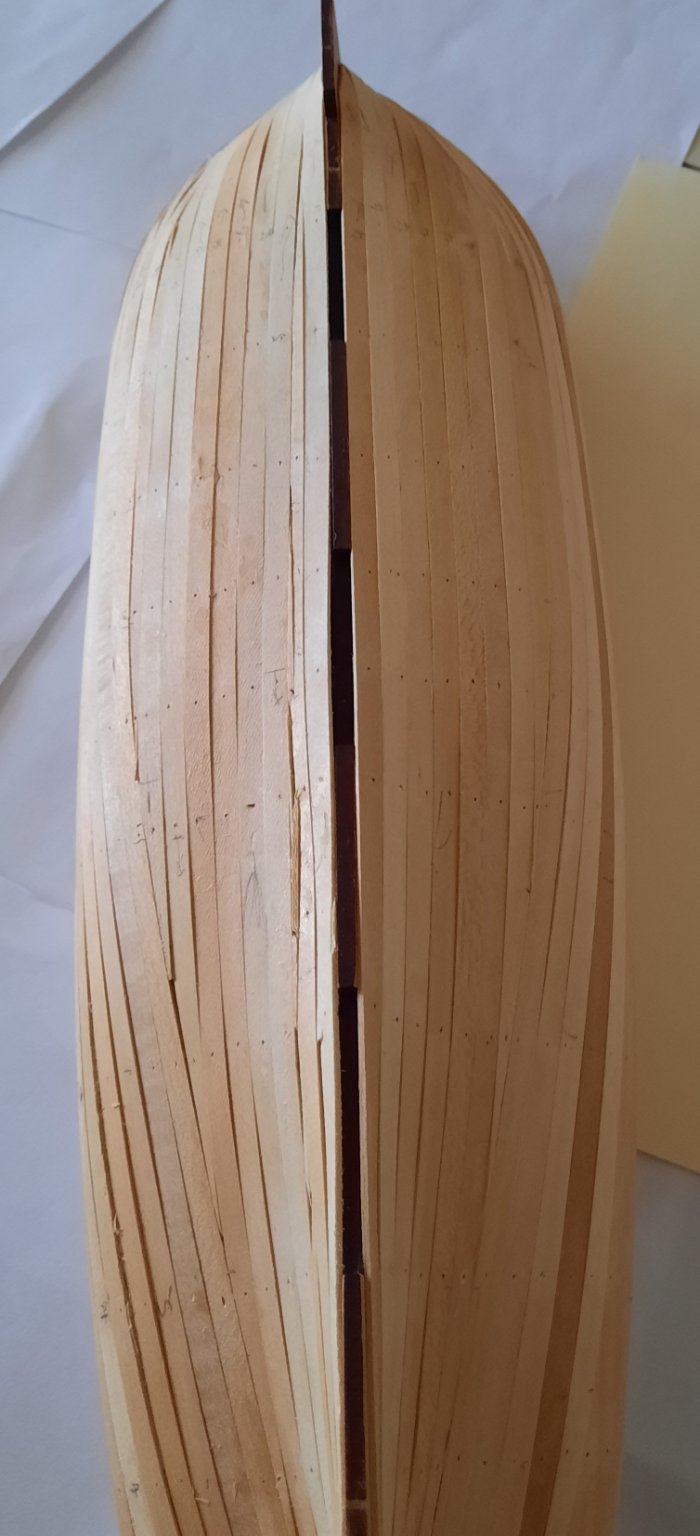
Stage: Hull Construction Build instructions: 74 Task: Fitting 1st Planking Sanding Parts: n/a Time Spent: 1 hour Status: In progress Build Notes: I have completed the trimming of the stern area. I used my craft knife and took my time to remove the excess material. I am pleased with how the stern area looked once this task was completed. I then started with the sanding of the 1st planking. This has gone very well and I now have a nice smooth looking hull. I used a mixture of different grits, starting with a 240 grit but using 60 to 100 grits for some areas initially and then reverting to a 400 grit. There are still a couple of things I need to check before I move on to the next phase of the build which are: a) I would like to look at the hull surface in natural daylight, it looks reasonable OK under the workshop lighting. I am tempted to add a thin coat of primer to highlight any areas which either proud or requires a bit of filler. The primer will be sanded back to the lime wood surface. b) I need to check the width (and sand as necessary) at the stern post area to ensure that the 2nd planking will sit flush with the stern post. As far as I aware there is nothing specified in build instructions but is something which does need to be checked and actioned.


- 382 replies
-
- 8
-
-
- Vanguard Models
- Duchess of Kingston
- (and 1 more)
-
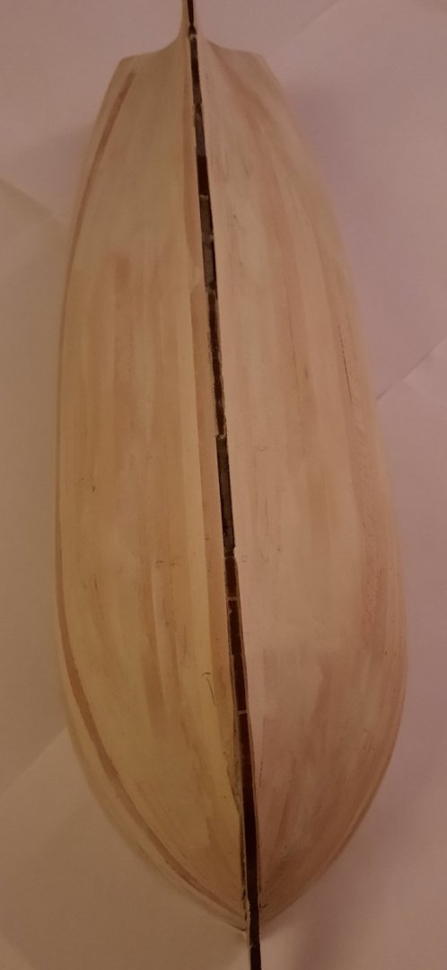
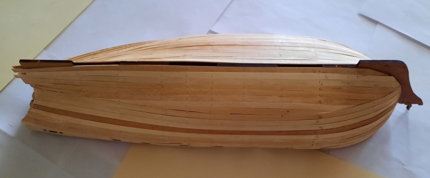
Stage: Hull Construction Build instructions: 71-73 Task: Fitting 1st Planking Parts: n/a Time Spent: 12 hours Status: Completed Build Notes: I have now completed the first planking stage and I have four full lengths of the planking material left over. I am happy with the result; it is certainly my best effort at 1st planking. The stern area now needs to be trimmed and tidied up before the hull undergoes a good sanding and filling, where necessary. I will certainly take my time with the sanding and filling to ensure I have a good solid smooth base. I may follow Chuck Passaro’s excellent method for lateral plank bending when I get around to adding the 2nd planking, especially above the water line. It worked really well when I used it on my Speedy build.

- 382 replies
-
- 10
-
-
- Vanguard Models
- Duchess of Kingston
- (and 1 more)
-
Thanks Dave. I did taper my early planks also. I just thought it would make a slightly neater job of the unseen first planking. I have completed the starboard side and I'm about 50% complete on the port side. I did find some of the cross beams had a habit of becoming dislodged also. You have a nice looking model.
- 382 replies
-
- 1
-
-
- Vanguard Models
- Duchess of Kingston
- (and 1 more)
-
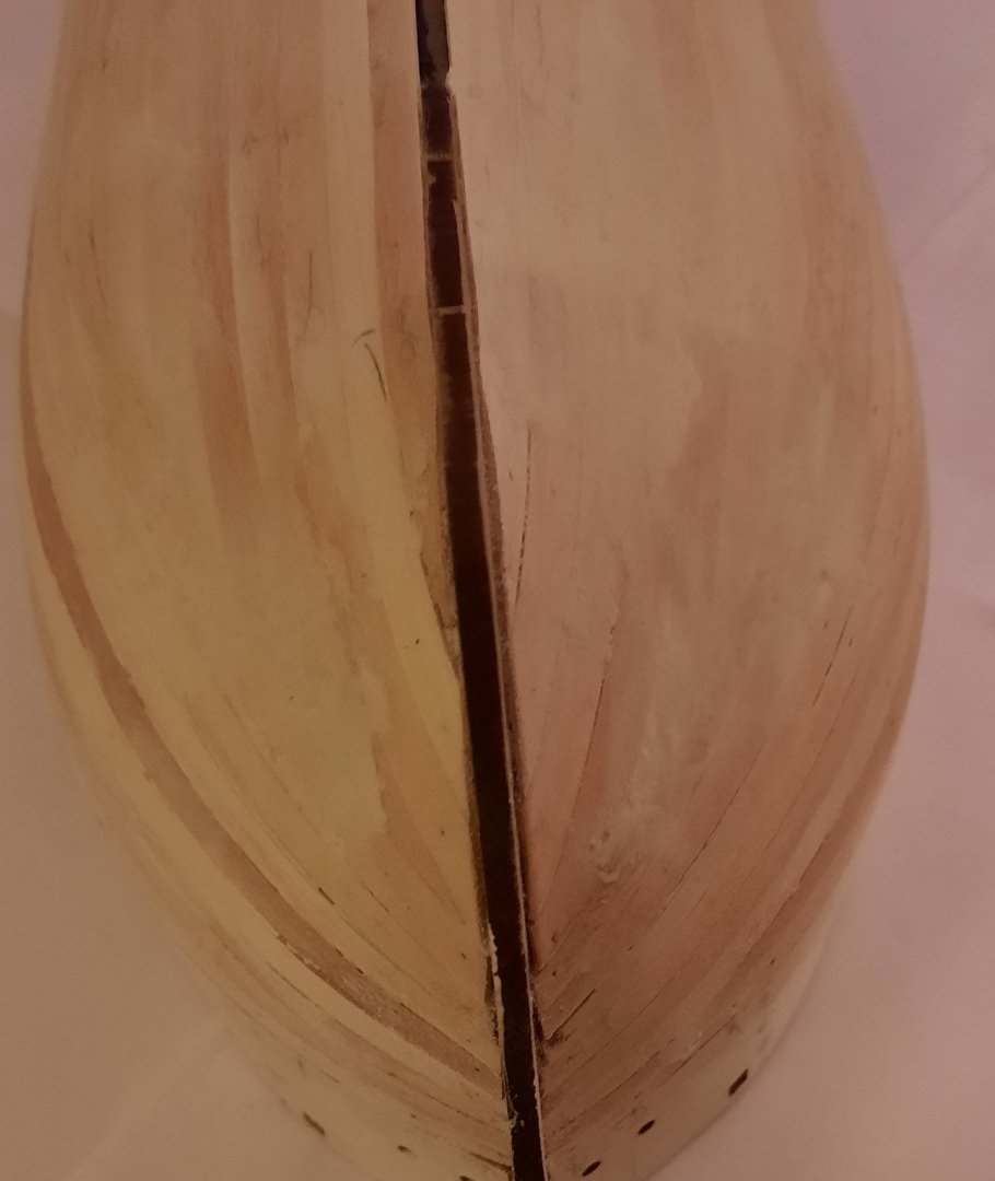
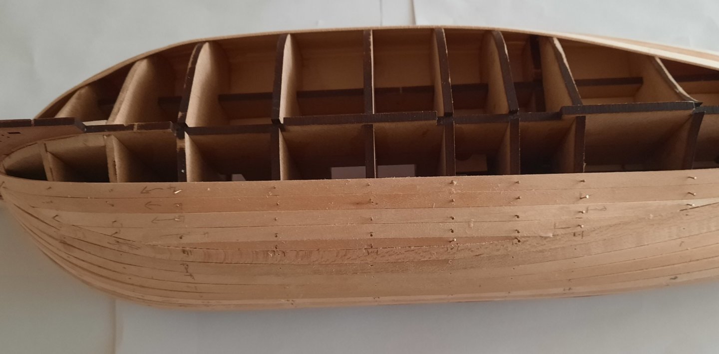
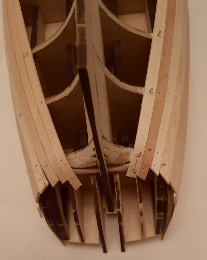
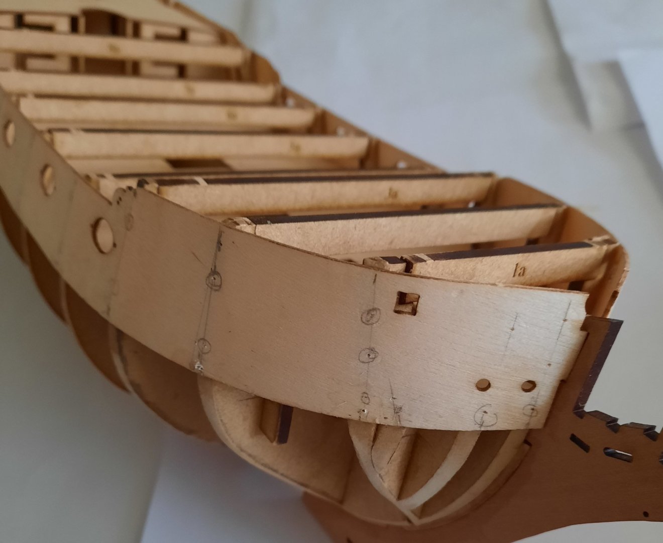
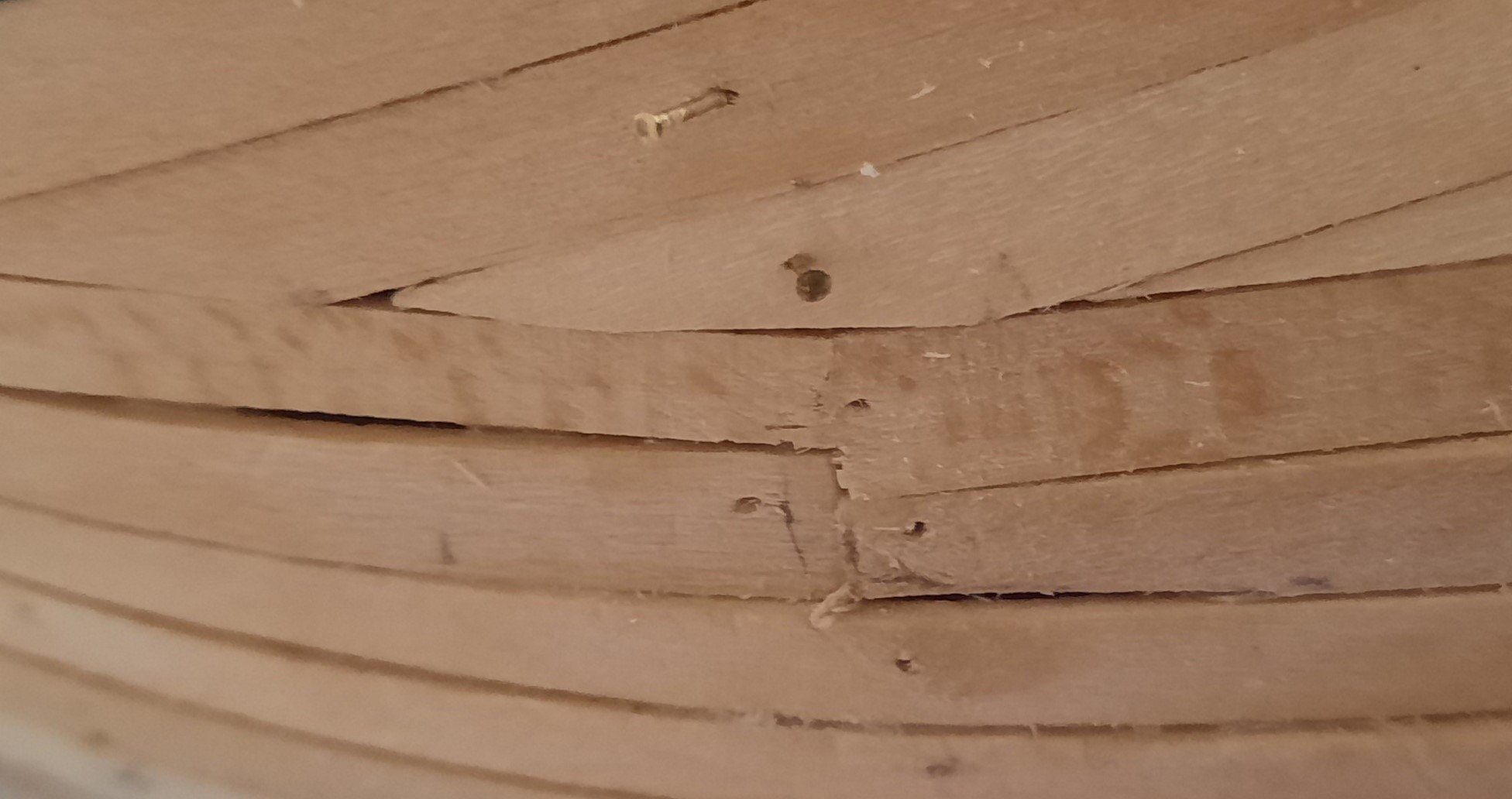
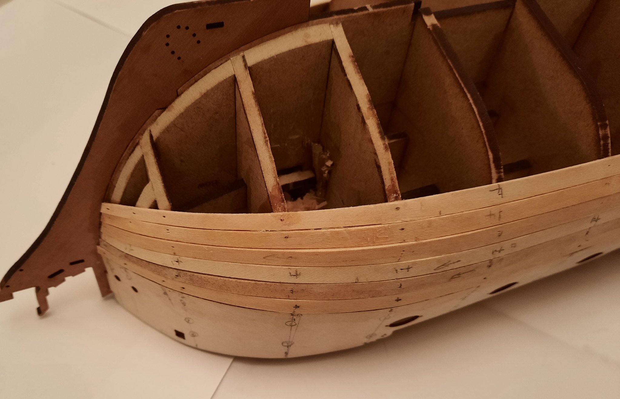
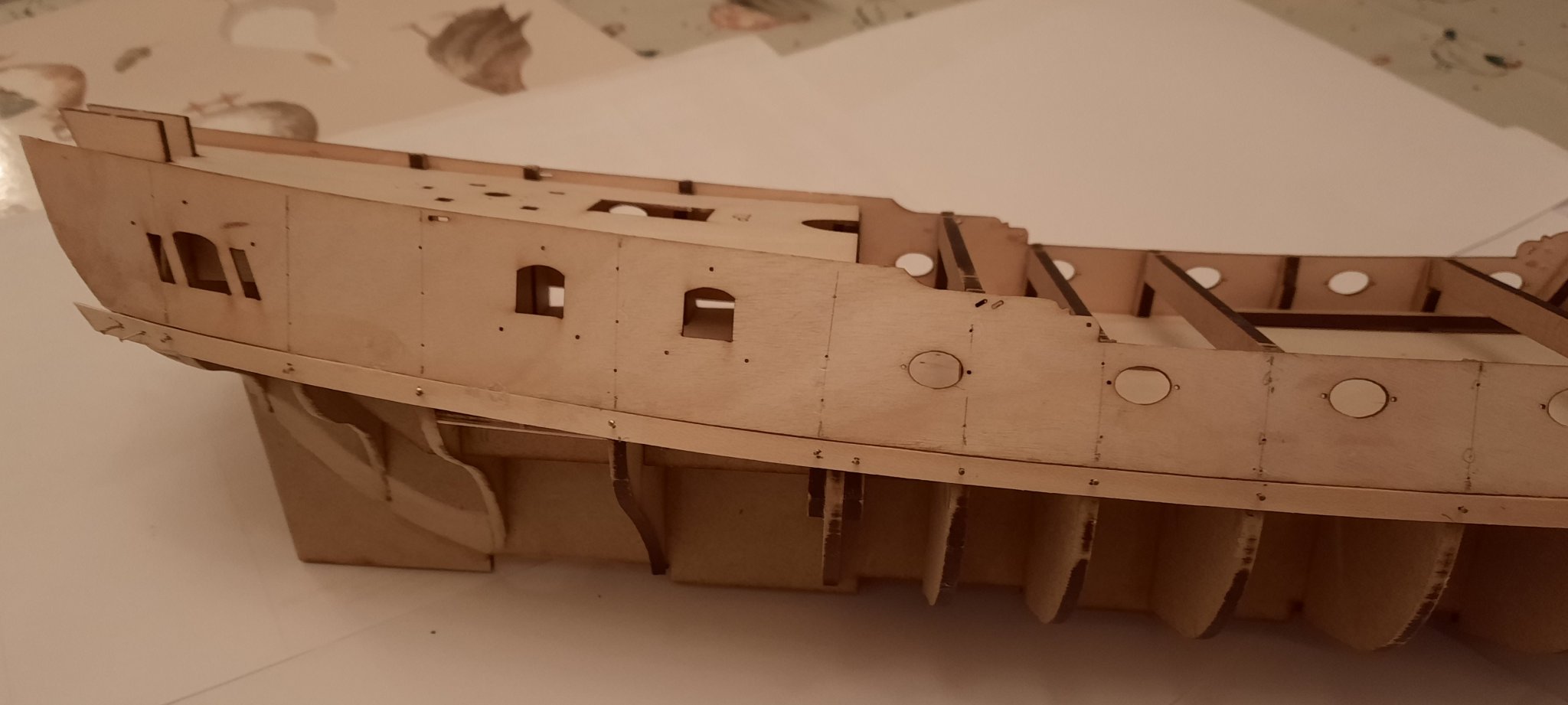
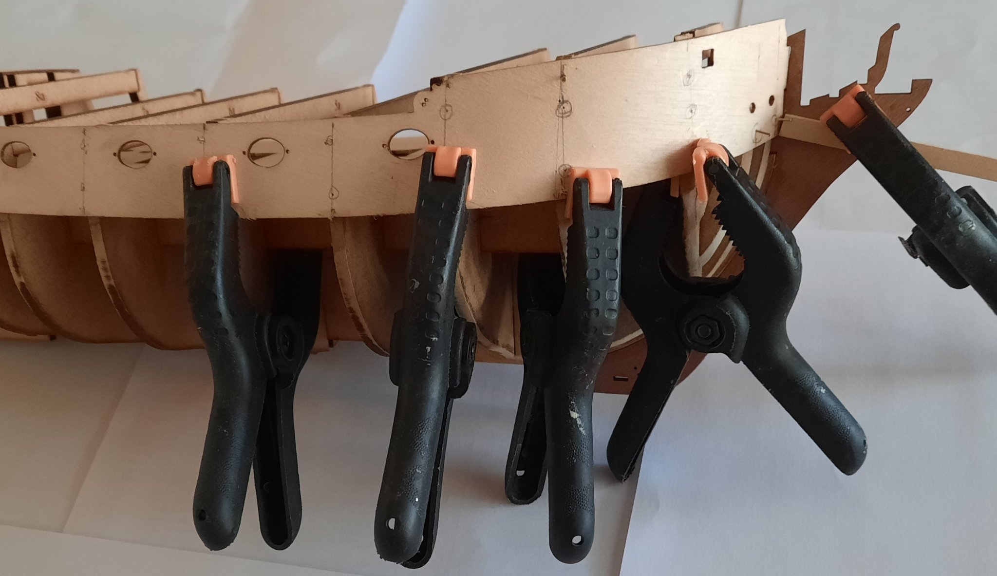
I'm making slow but steady progress with my first planking. I ended up fitting a short steeler plank around the bow area as I was fitting planks 7 and 8. In reality this was not strictly necessary but it I think it helped. After fitting the 8th plank I found it necessary to adjust the position of the 9th planking order for it to run along its natural path, as can be seen in the photo below. I tried to leave a gap, at the widest point equal to either 3 or 4 plank widths for the infill. I ended up with a gap of approx. 3.5 plank widths. Fortunately this was not an issue as the final short filler plank did not require much effort to shape it to fit.


- 382 replies
-
- 10
-
-
- Vanguard Models
- Duchess of Kingston
- (and 1 more)
-
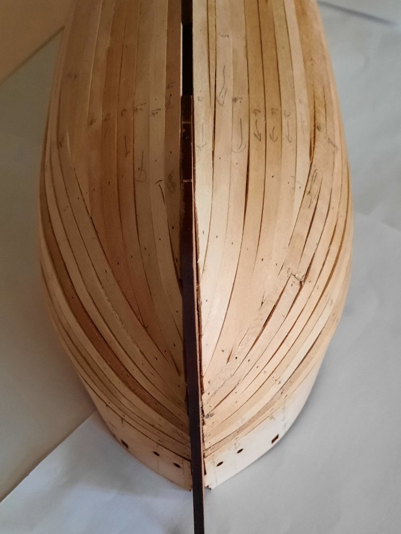
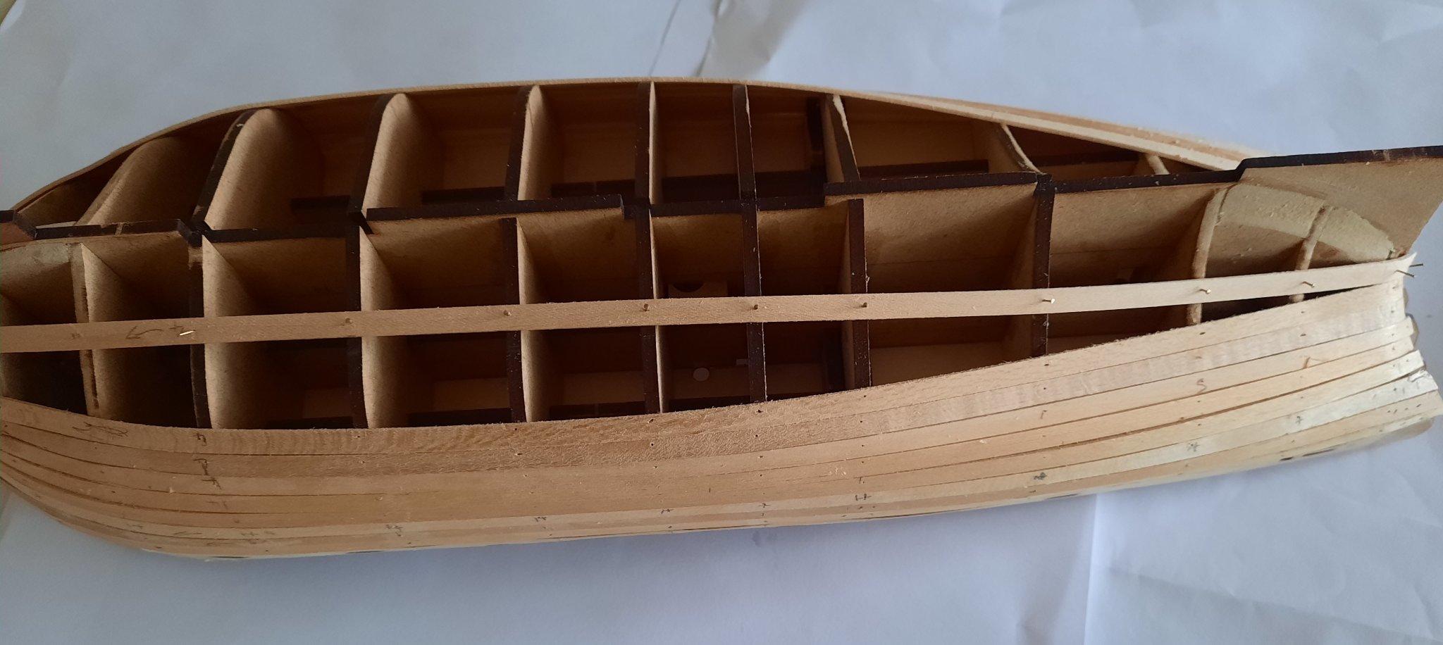
I have continued on with the 1st planking today and I now have fitted 6 planks to each side. I did a time and motion study on fitting the planks, and concluded it takes around 20 to 30 mins per plank to fit. It did start out at around 30 mins but I have been able to streamline the process to around 20 mins per plank now I'm confident with my methodology. I would expect this task will take between 12 to 16 man hours to complete. I am brushing in a diluted wood glue along the joint line after each plank is fitted, and I have noted a couple of planks are sitting a bit proud of the bulkheads in a couple of places. I was able to sort one out with dripping in some super glue and then holding in place whilst the ca cured. So far this is the best first planking I have achieved in my modelling career, applying the lessons learned in previous builds and have patience (I'm normally have little or no patience) and simply taking my time. I have reglued the raised plank that can be seen on the right hand side at the bow pattern.

- 382 replies
-
- 11
-
-
- Vanguard Models
- Duchess of Kingston
- (and 1 more)
-
Darrel. I hope you will enjoy the build as much as I am. I'm no expert but I do enjoy posting regular updates detailing my experiences.
-
Stage: Hull Construction Build instructions: 70-74 Task: Fitting 1st Planking Parts: n/a Time Spent: 30 mins Status: In progress Build Notes: Looking at the build manual photo’s I have counted 17 planks per side, therefore 34 planks required in total. The kit is supplied with 34 off lime planks. Hopefully, I will not make any mistakes with the planking. I am not rushing this task so I think it will take a few days to complete. I did not apply any plank bending when I fitted the first plank as it bent quite easily. In retrospect I think this was a mistake and for the subsequent planks I have been using my trusty plank bender to add the bend from approx. bulkhead 4 to the bow pattern. Although this is adding more time and effort to the build process, I am getting a much better result. I have now fitted 4 planks to the starboard side and I found it necessary to trim each plank around the bow area, (bulkheads 1-3). I also found it necessary to trim a small slither between bulkheads 12 and 13 for the fourth plank. I also used my plank bender on the end of the fourth plank for the stern area.


- 382 replies
-
- 15
-
-
- Vanguard Models
- Duchess of Kingston
- (and 1 more)
-
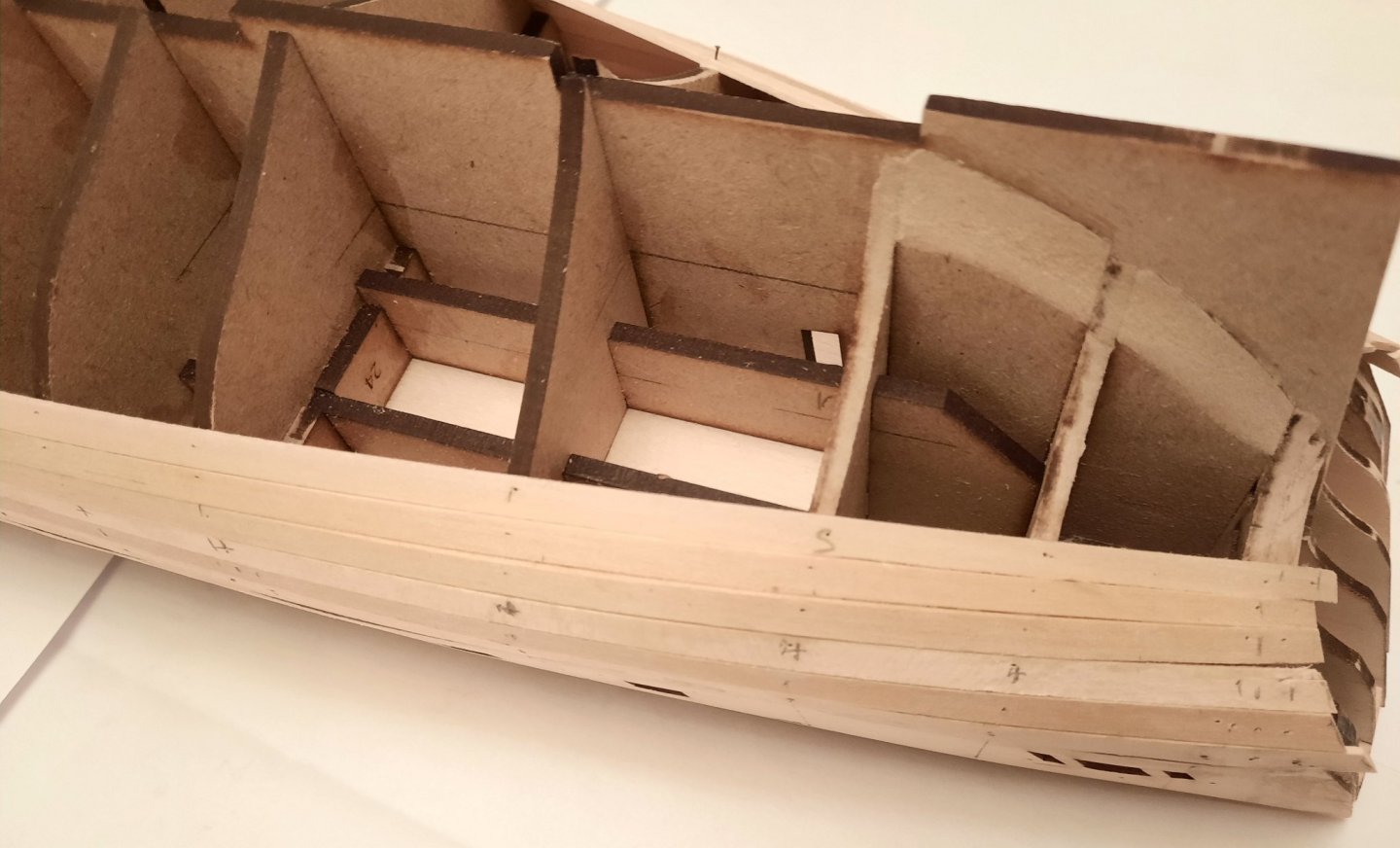
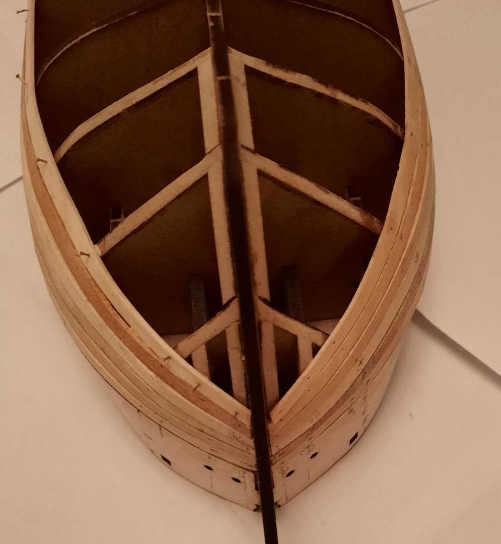
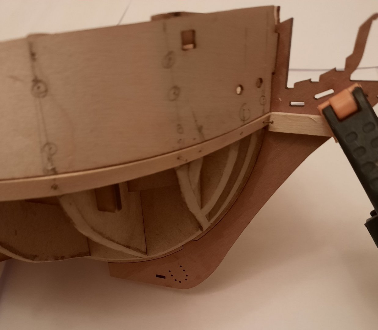
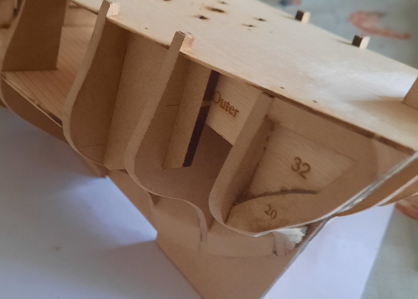
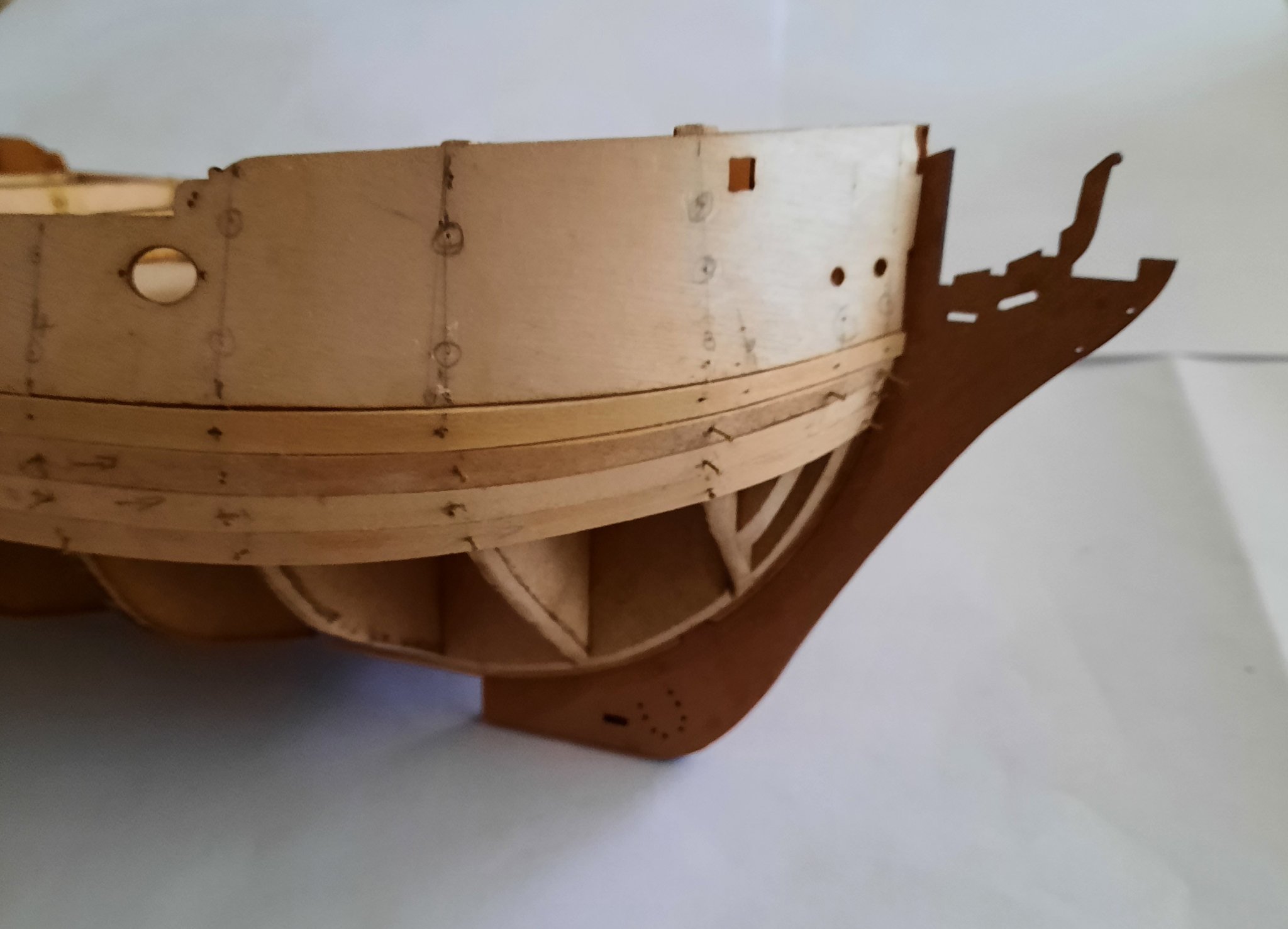
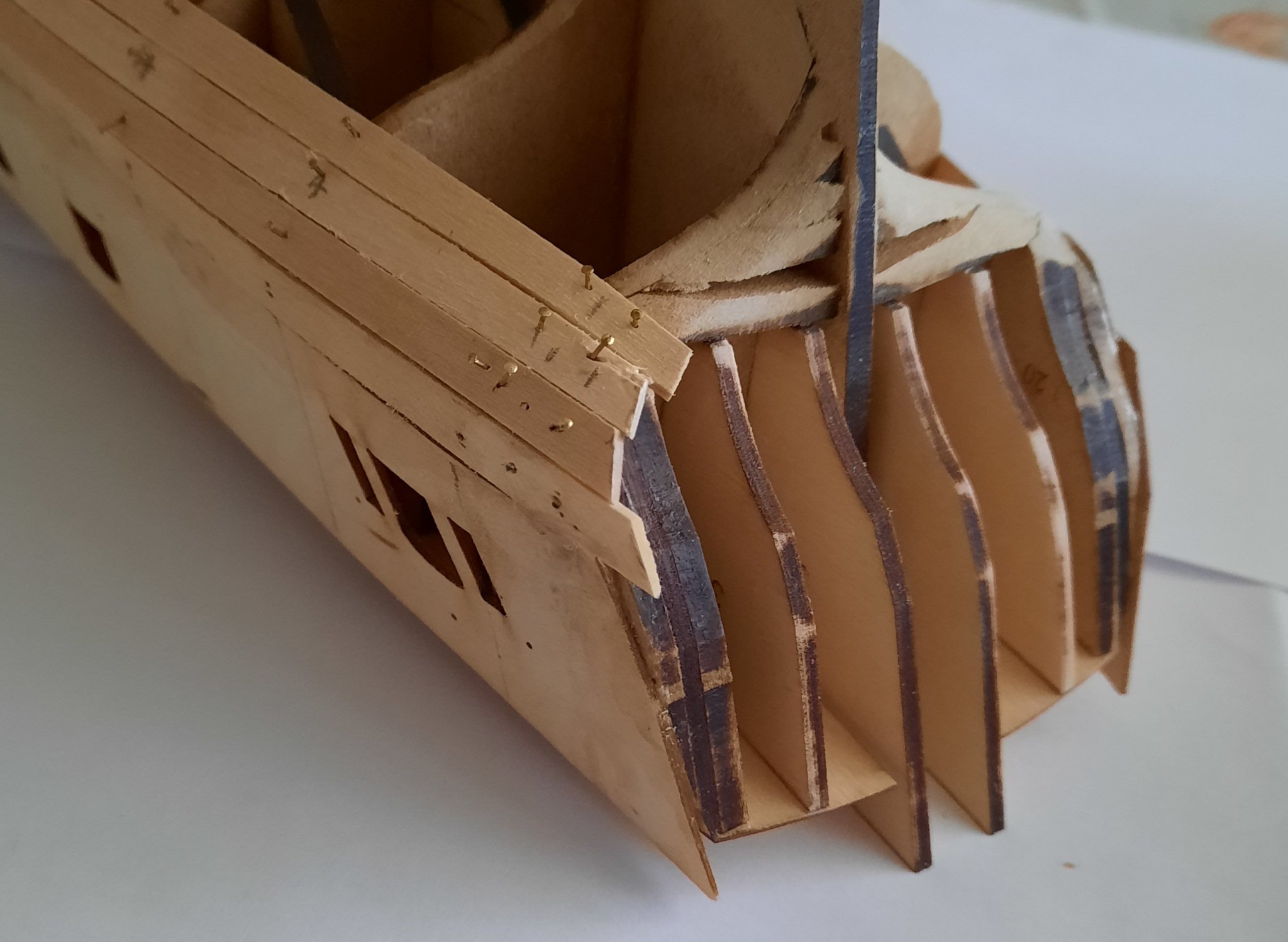
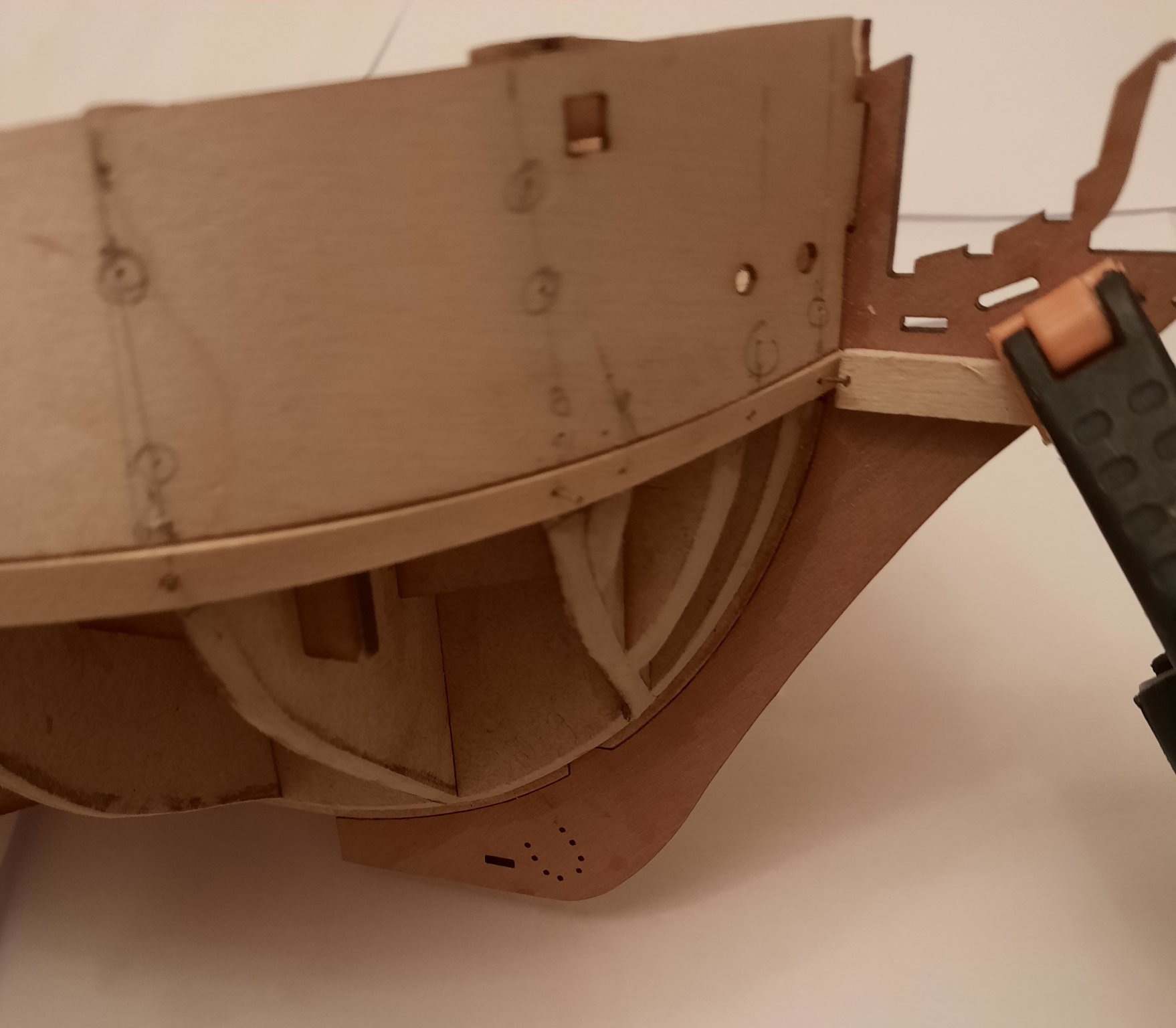
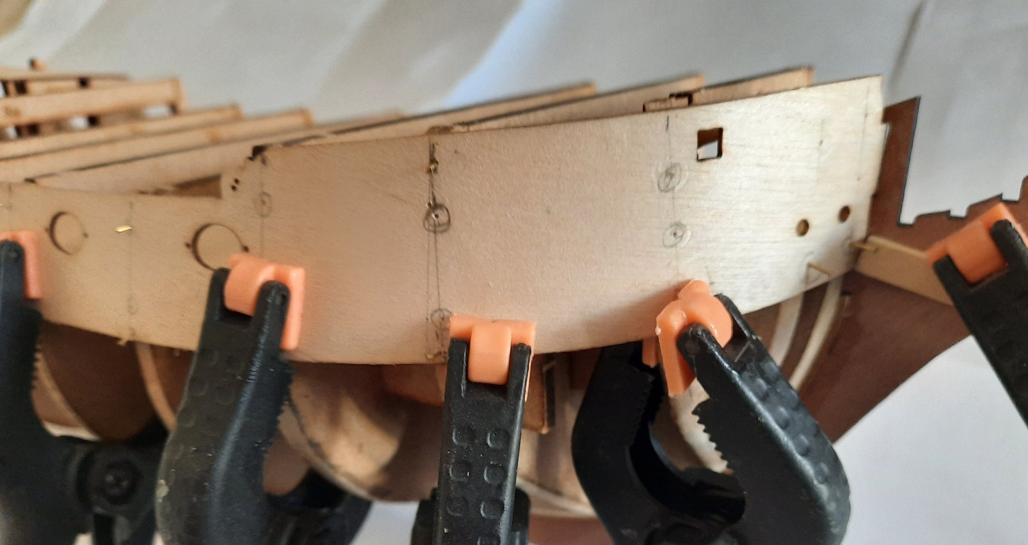
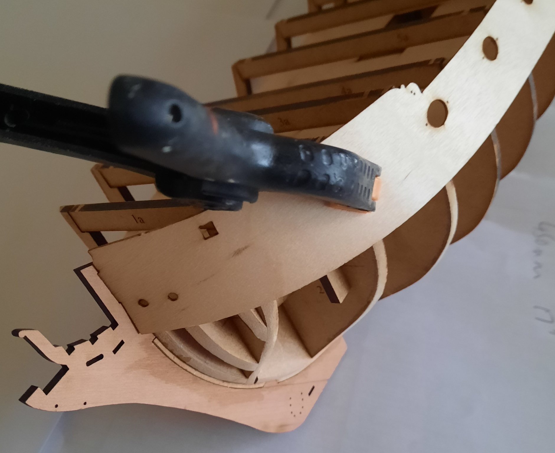
Stage: Hull Construction Build instructions: 70-74 Task: Fitting 1st Planking Parts: n/a Time Spent: 30 mins Status: In progress Build Notes: I have now made a start on the 1st planking. As advised in the build instructions it is necessary to add a taper to the 1st plank. I found the taper needed to start at bulkhead 2 and I tapered from 4mm to a width of 2mm at the bow pattern. With the plank held in position I was able to mark the position of all the bulkheads and then pre-drilled the plank using a 0.4mm drill in readiness for adding the planking pins. With the plank in place I also felt it would be advantageous to add a filler piece in the stern area. This was an easy task using some scrap 1.5mm planks from a previous build to fill area around stern pattern 20. I have shown this in the photo below. I also noted that it was necessary to add a lateral chamber along the top (bulwark) edge of the plank between bulkheads 9 to 13 to ensure the plank formed a nice clean joint with the bulwark. I think it is important to get the first plank looking good, especially along the top (bulwark edge) so I did take some time to make sure the plank looked good. Once I was happy with the fit I brushed some wood glue to the bulkheads and inserted the pins in the pre drilled holes. I started at bulkhead 4 and worked toward the bow using my pin pusher to secure the plank in place. As can be seen in the photo(s) below I clamped a scrap piece of wood at the bow pattern area. I then worked backwards from bulkhead 5 to bulkhead 13 and I was really glad I added the stern filler. Once the plank had been pinned I brushed a diluted wood glue solution along the joint between the plank and bulwark
- 382 replies
-
- 11
-
-
- Vanguard Models
- Duchess of Kingston
- (and 1 more)
-
Thanks, I find completing the first planking to be a real milestone and a big weight off my mind once it is done.
- 382 replies
-
- 2
-
-
- Vanguard Models
- Duchess of Kingston
- (and 1 more)
-
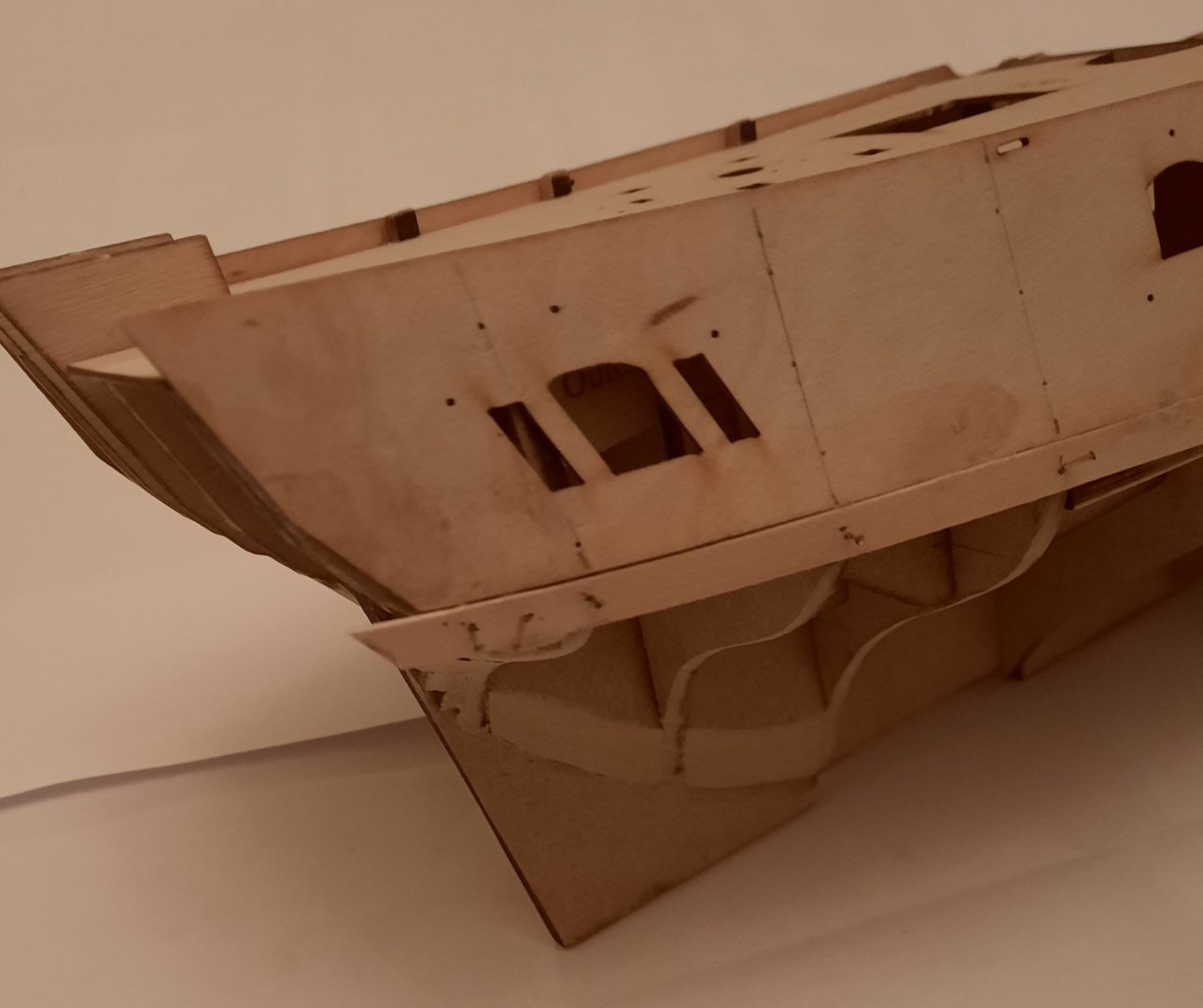
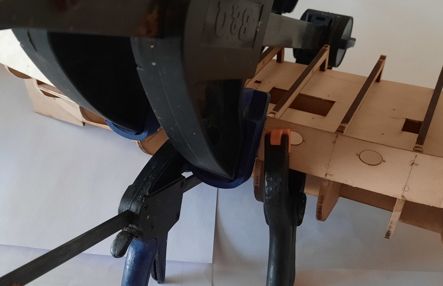
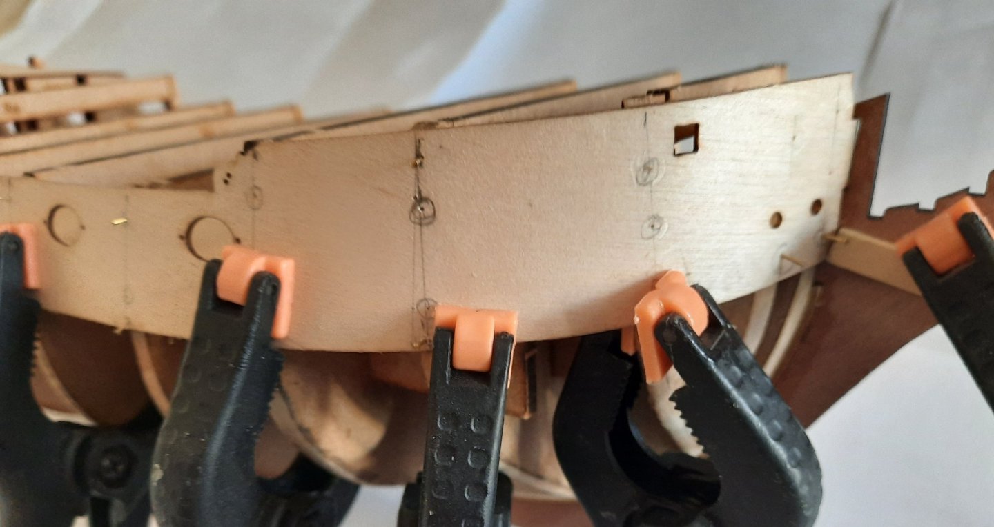
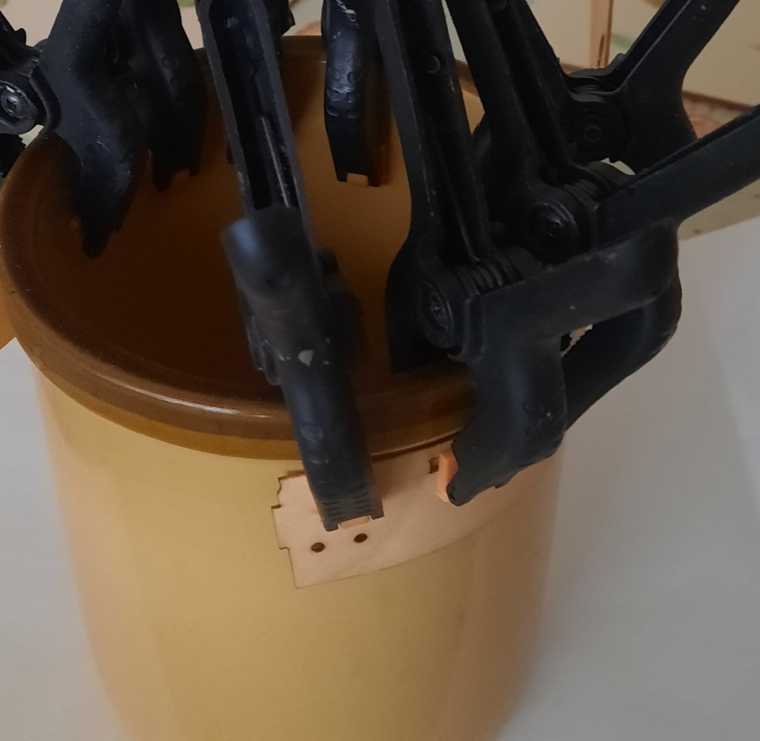
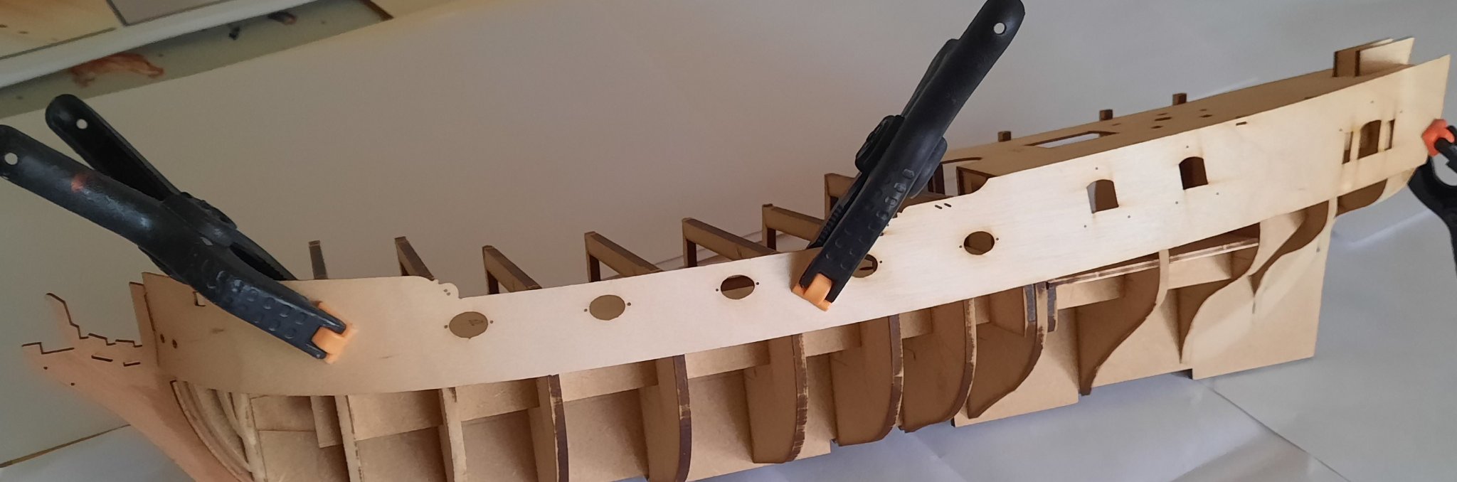
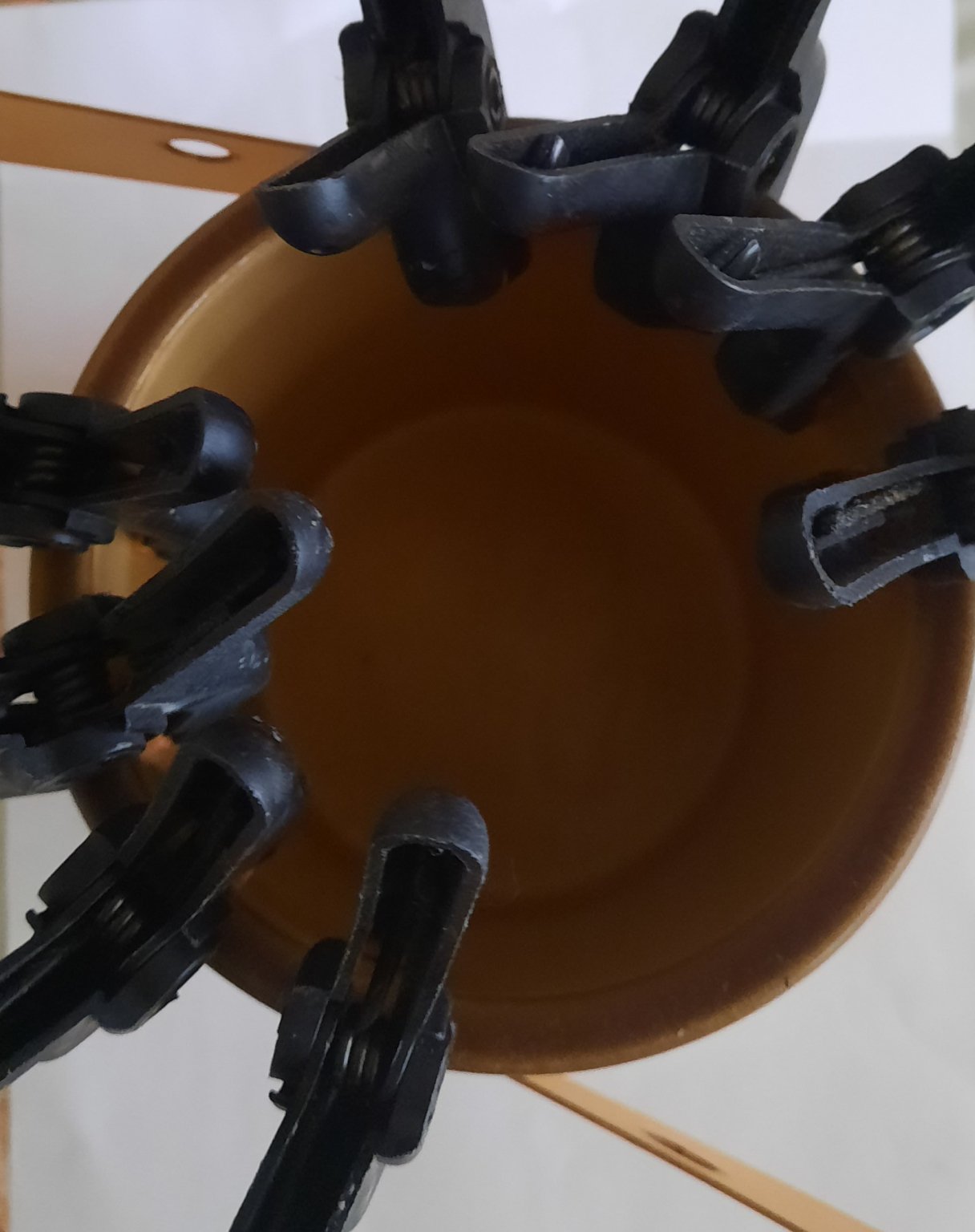
Stage: Hull Construction Build instructions: 70 Task: Fitting Bulwark Patterns Parts: 45 (x2) Time Spent: 120 mins Status: Complete Build Notes: After soaking the two strips in hot water for 30 mins and clamping the bow ends around a circular container for 22 hours and then being very happy with the dry fit I thought the actual fitting of the bulwark patterns was going to be pretty straightforward. As mention in my previous post I had to remove the starboard strip and start again as I was not happy with how it was looking. 2nd time around by fitting the strip in stages using a mixture of pins and clamps to ensure I was getting a good join with the bulkheads and deck edge as I went along. This method worked well for me and I was happy with how the strip fitted I used the same method for the port side bulwark and that went on nicely without two much effort. After I removed all the pins and clamps and did a final visual check and noted a small area where the port side bulwark was sitting a tad proud along the deck edge between bulks 5 & 7. I brushed in some wood glue and applied a bit of light pressure with using two spreader clamps, as can be seen in the photo below. A couple of hours later I removed the two spreader clamps and I was happy with the bulwarks fitting as shown in the next photos. I am now in a position to start the 1st hull planking as per build instructions 71 to 74.
- 382 replies
-
- 12
-
-
- Vanguard Models
- Duchess of Kingston
- (and 1 more)
-
The starboard side is now installed and looks good. I jumped ahead of my plan and started with the port side which is going on much easier. I have fitted it from bow to bulkhead 8 without any problems.
- 382 replies
-
- 3
-
-
- Vanguard Models
- Duchess of Kingston
- (and 1 more)
-
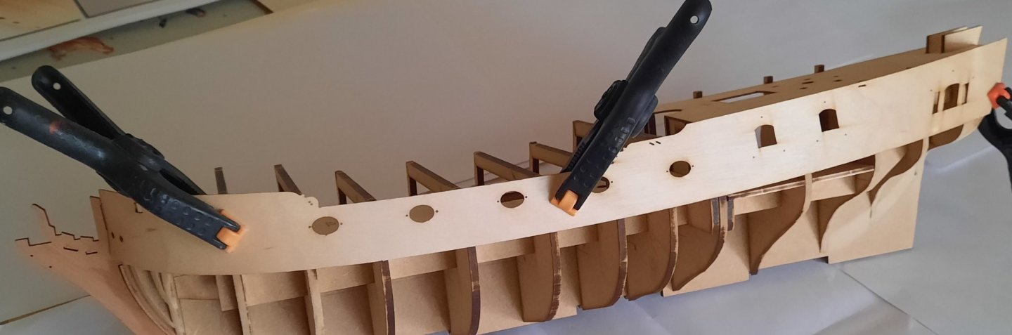
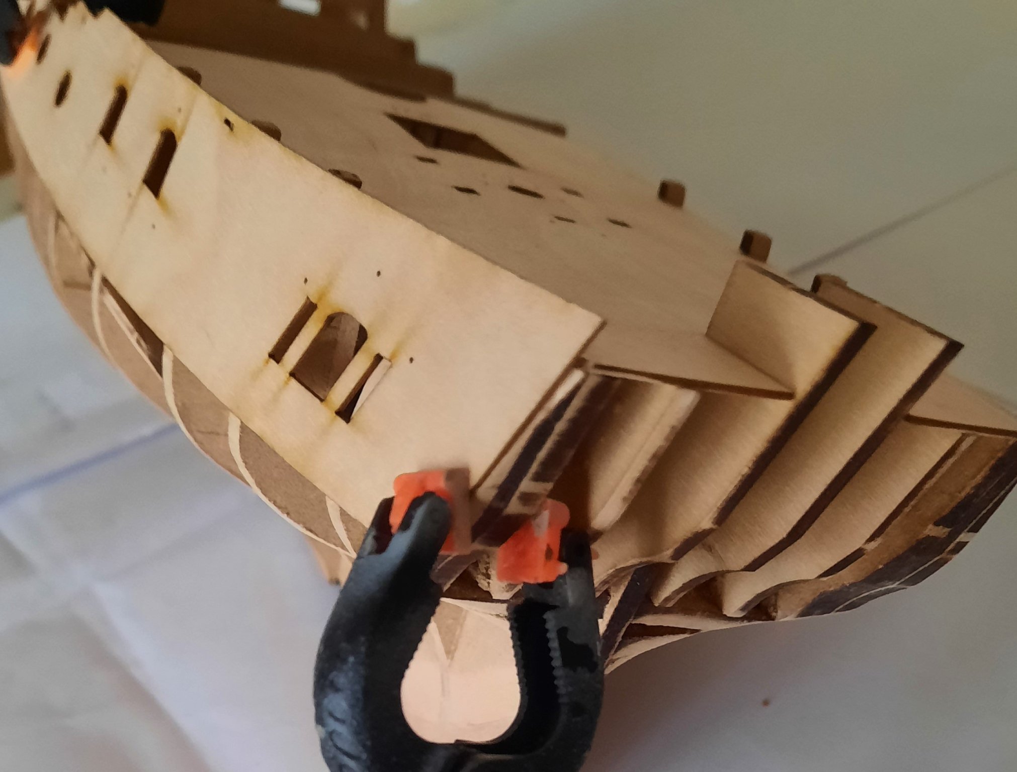
Today's plan was to fit both outer bulwark and to then start the 1st hull planking. Gluing the outer bulwark, however, has proven to be a bit more of a challenge than I expected. I pre drilled the bulwark with 0.5mm holes (as per the instructions) at the joint areas with the bulkheads. I then applied a liberal coating of wood glue to the bulwarks and to the edge of the deck. After I had pinned the first bulwark in place I noted that in a few areas it was not making contact with the bulkheads. I added some elastic bands to assist which did help in some places. As I was not very happy with how it was looking, especially around the bow area, and before the glue had fully cured I decided to remove the bulwark and to start again with a more targeted and patient approach. I started by getting the bulwark looking right at the bow and the first bulkhead. I also used a small plank to aid the positioning at the bow, as can be seen in the picture. Once I was happy with the positioning I then added glue to bulkheads 2 & 3. As the strip, even when pinned, was not seated properly at bottom edge I added some clamps to provide additional pressure whilst the glue cured. I then glued and pinned the bulwarks to bulkheads 4 - 6 using clamps for additional support and left the glue to cure. Next I added glue to bulkheads 7 - 9 and once again using a mixture of pins and clamps to hold the strip in place. And that is the current state of play. I will move on to the stern area in a couple of hours time and should be able to glue from 10 - 13 in one go. Then tomorrow I will repeat for the other bulwark.

- 382 replies
-
- 11
-
-
- Vanguard Models
- Duchess of Kingston
- (and 1 more)
-
Darrel Take a look at Derek's build log, there are great examples with photos. I have provided a link to the deadeyes, but there are plenty rigging blocks earlier in the build log
-
I have used my quad hands today and successfully practiced rigging some deadeyes. Thanks to Derek's excellent tutorials in this build log I have achieved some much better results.
- 725 replies
-
- 3
-
-
- vanguard models
- speedy
- (and 1 more)
-
I am happy to report the rebent bulwark now fits perfectly. They are both clamped to the hull and I have given them both a liberal brushing with warm water. I will now leave them to settle in to shape overnight. I will then glue both strips in place tomorrow morning and I can then start the 1st hull planking thereafter.
- 382 replies
-
- 3
-
-
- Vanguard Models
- Duchess of Kingston
- (and 1 more)
-
I did consider using a hair dryer but decided to let nature take its course. I wanted to practice some rigging techniques, based on Derek's (delf) methods. I also needed to keep working on my other build project.
- 382 replies
-
- 1
-
-
- Vanguard Models
- Duchess of Kingston
- (and 1 more)
-
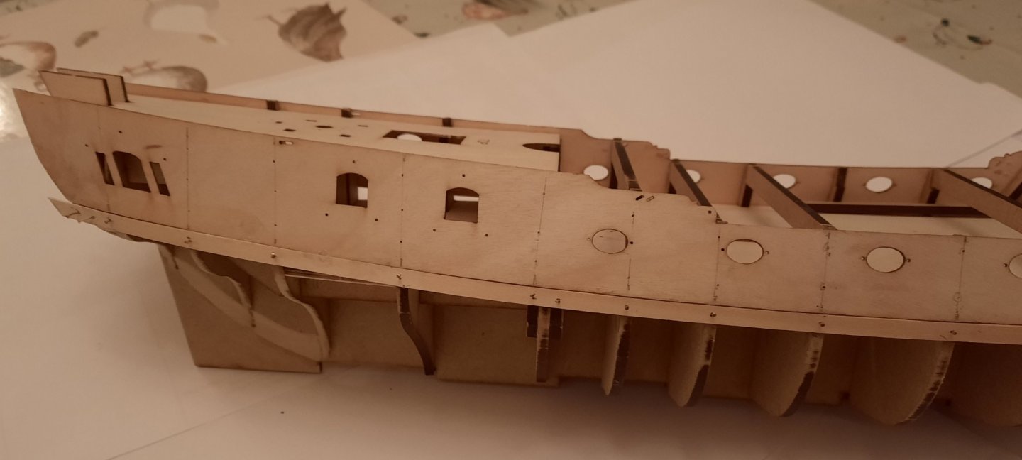
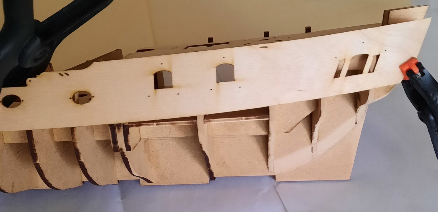
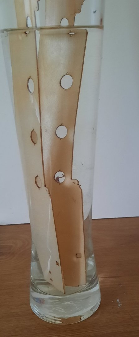
Just a quick update now the two bulwark patterns (45) have fully dried out after been clamped for 22 hours. Port Bulwark Pattern The port side bulwark pattern fitted like a dream, as can be seen in the following pictures. It has not been glued and pinned in to place just yet, as it needs it starboard buddy to be ready for action! Starboard Bulwark Pattern I had a minor mishap with the starboard bulwark pattern. I do not know how much longer I can use the " having a senior moment" excuse.🤔 I think the following picture will show why I should be nominated for the MSW "Numpty of the Week" award. 😂. Needless to say the pattern is once again in hot water for 30 mins in readiness for another overnight session with the clamps.


- 382 replies
-
- 14
-
-
- Vanguard Models
- Duchess of Kingston
- (and 1 more)
-
I keep looking at James's log and I lost count the number of times I have read the manual. I'm glad you are enjoying my build log.
-
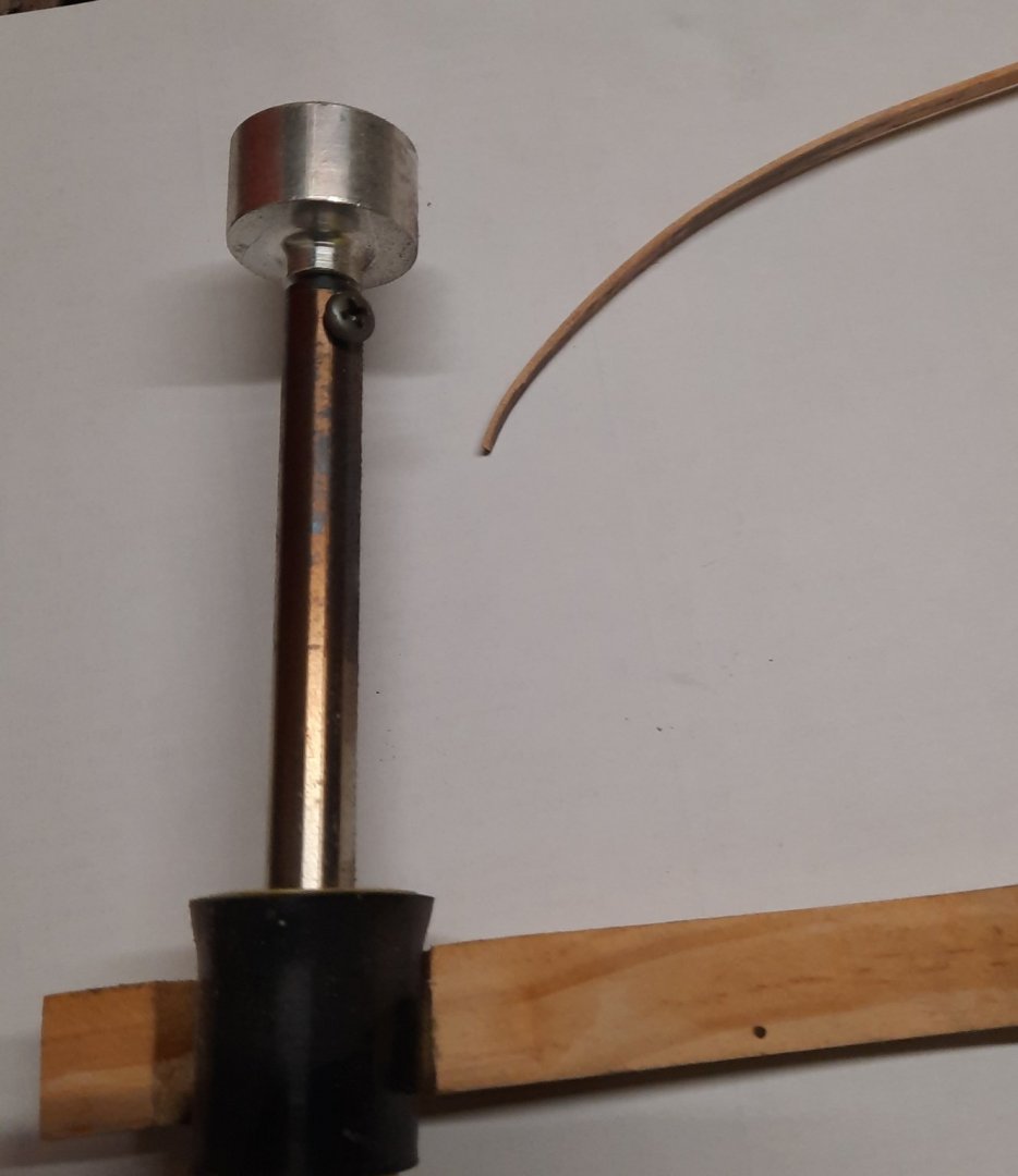
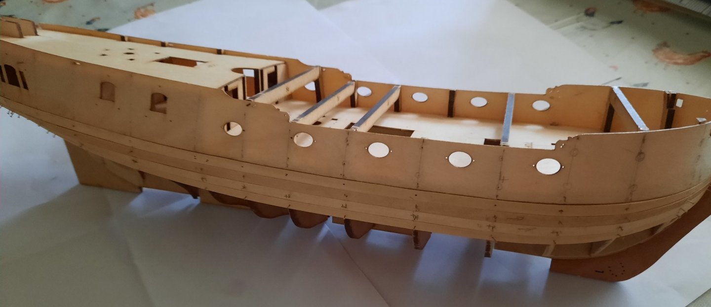
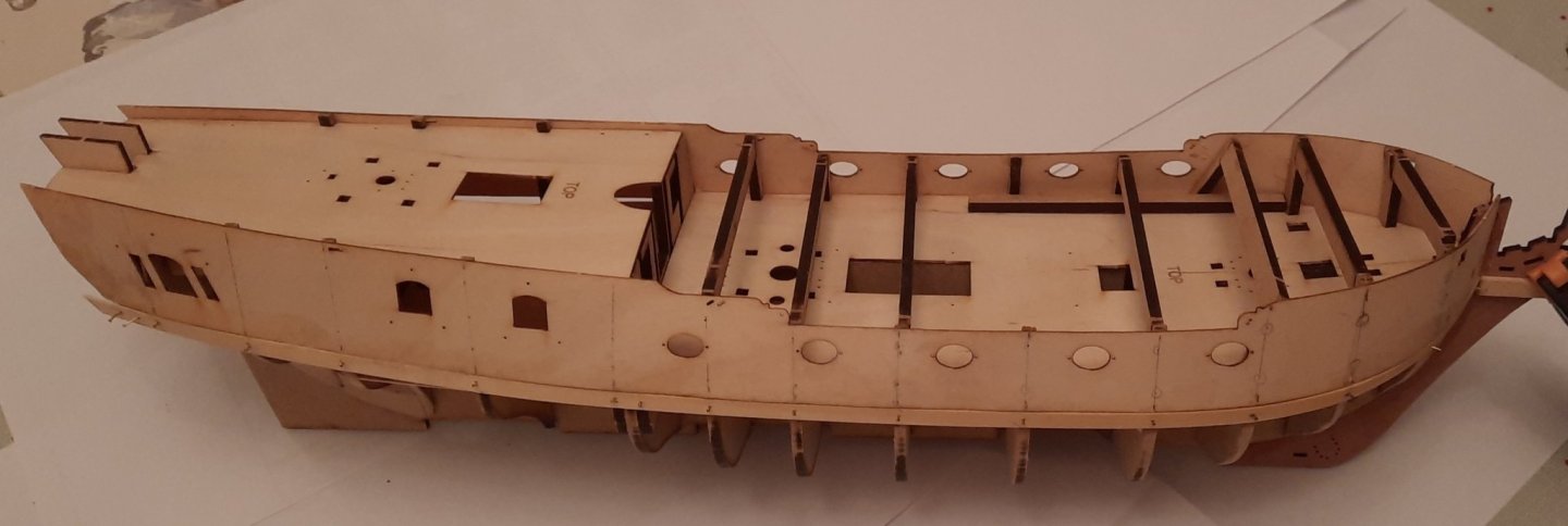
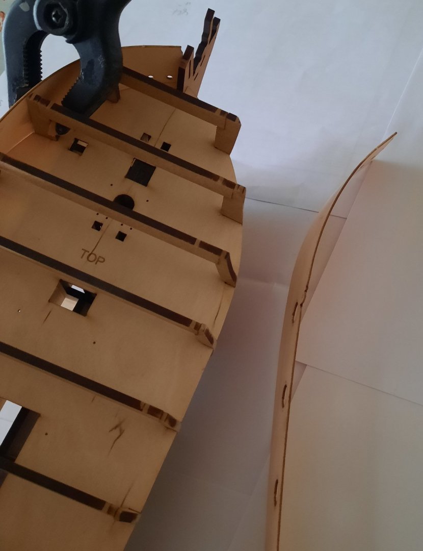
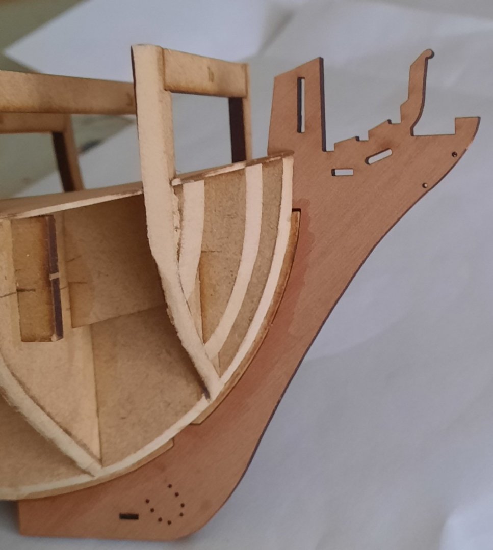
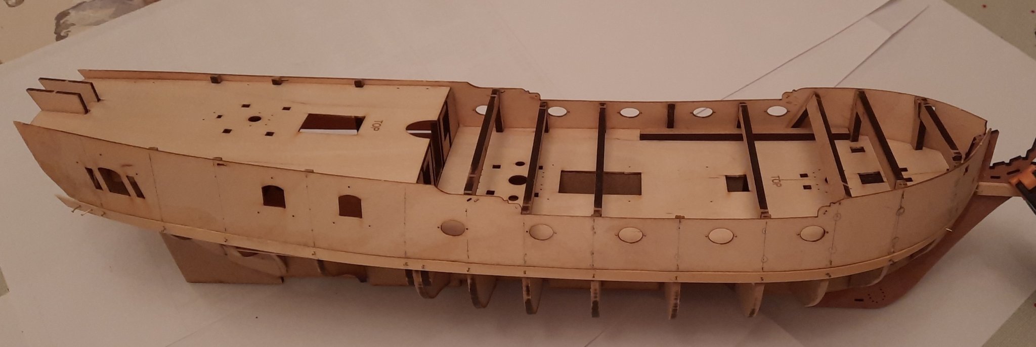
Stage: Hull Construction Build instructions: 67-70 Task: Bow and Bulwark Patterns Parts: 45 (x2) & 49 Time Spent: 10 mins Status: Complete Build Notes: I did a test fit of the bow pattern (49) As it was a very good fit I removed it and brushed on some wood glue to the contact areas and slotted the pattern back in place. Although I didn’t think the bow pattern needed clamping, I did use a couple of clamps to ensure the part remained properly aligned whilst the glue cured. The two bulwark patterns (45) were then soaked in hot water. After 30 mins I removed then and clamped then around a round jar to get the required bow shaping. They will now stay clamped for approx. 22 hours which will give the patterns plenty of time to fully dry. I jumped ahead to have a look at the next task, after the completion of the 1st hull planking. I decided to remove the fore and aft keel parts and test fit them to the hull along with the stern post assembly. (build instructions 75 – 78). I was pleased with how these parts looked when dry fitted and they will now be stored away for safe keeping. I was tempted to assemble some the desk items, such as the cannons, gallows and main mast bits, bilge pumps, hatchings, etc. but I have resisted the temptation as I need to spend a bit of time with my Robert E Lee build project.

.thumb.jpg.1294decc550e0942cf71203e483be525.jpg)
- 382 replies
-
- 8
-
-
- Vanguard Models
- Duchess of Kingston
- (and 1 more)
-
Looks like you may be busy
-
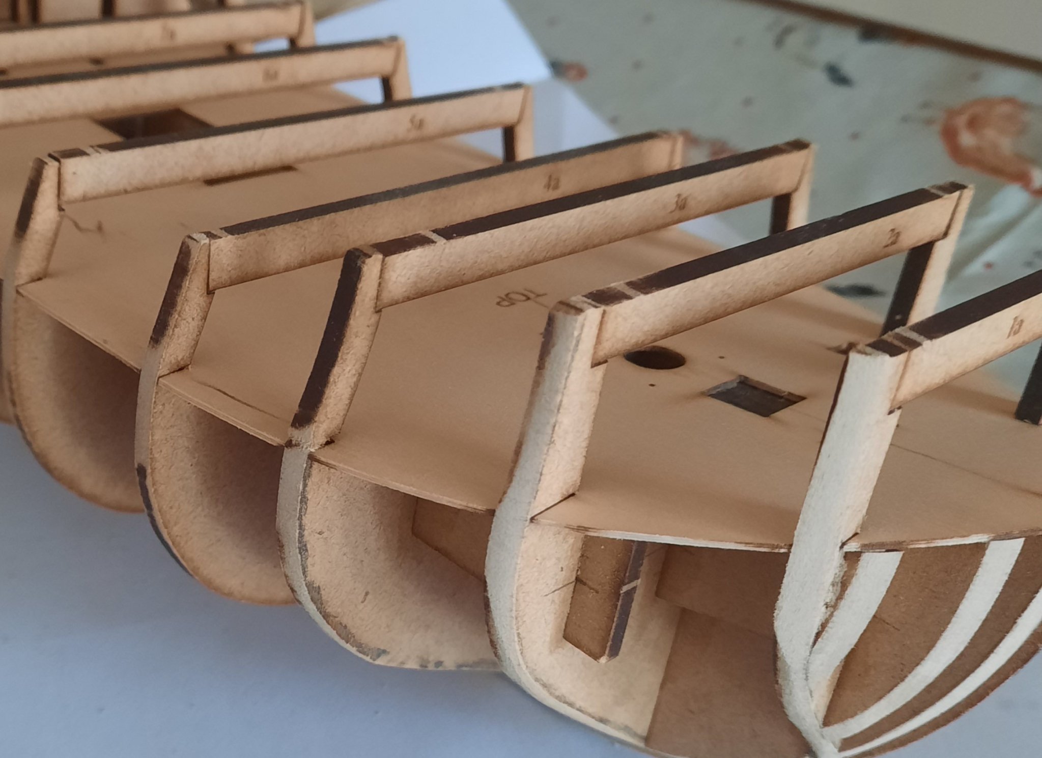
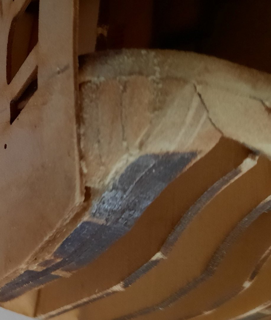
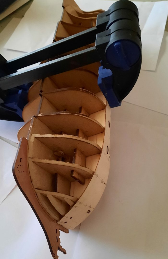
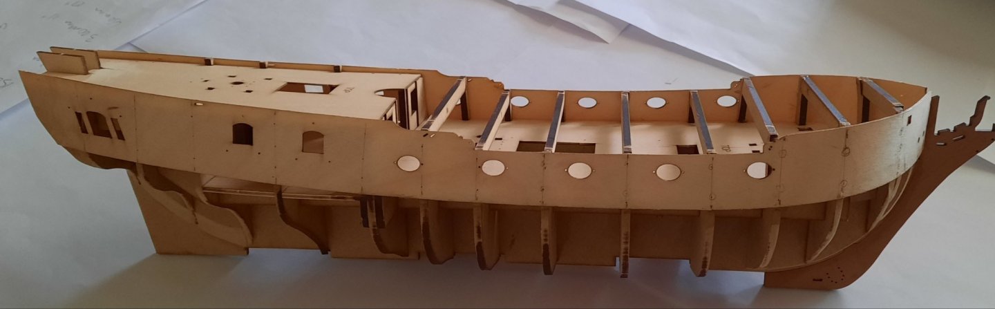
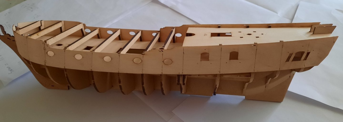
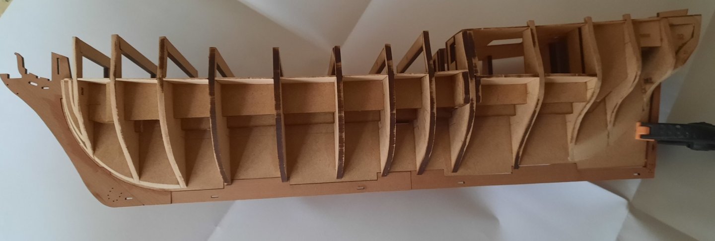
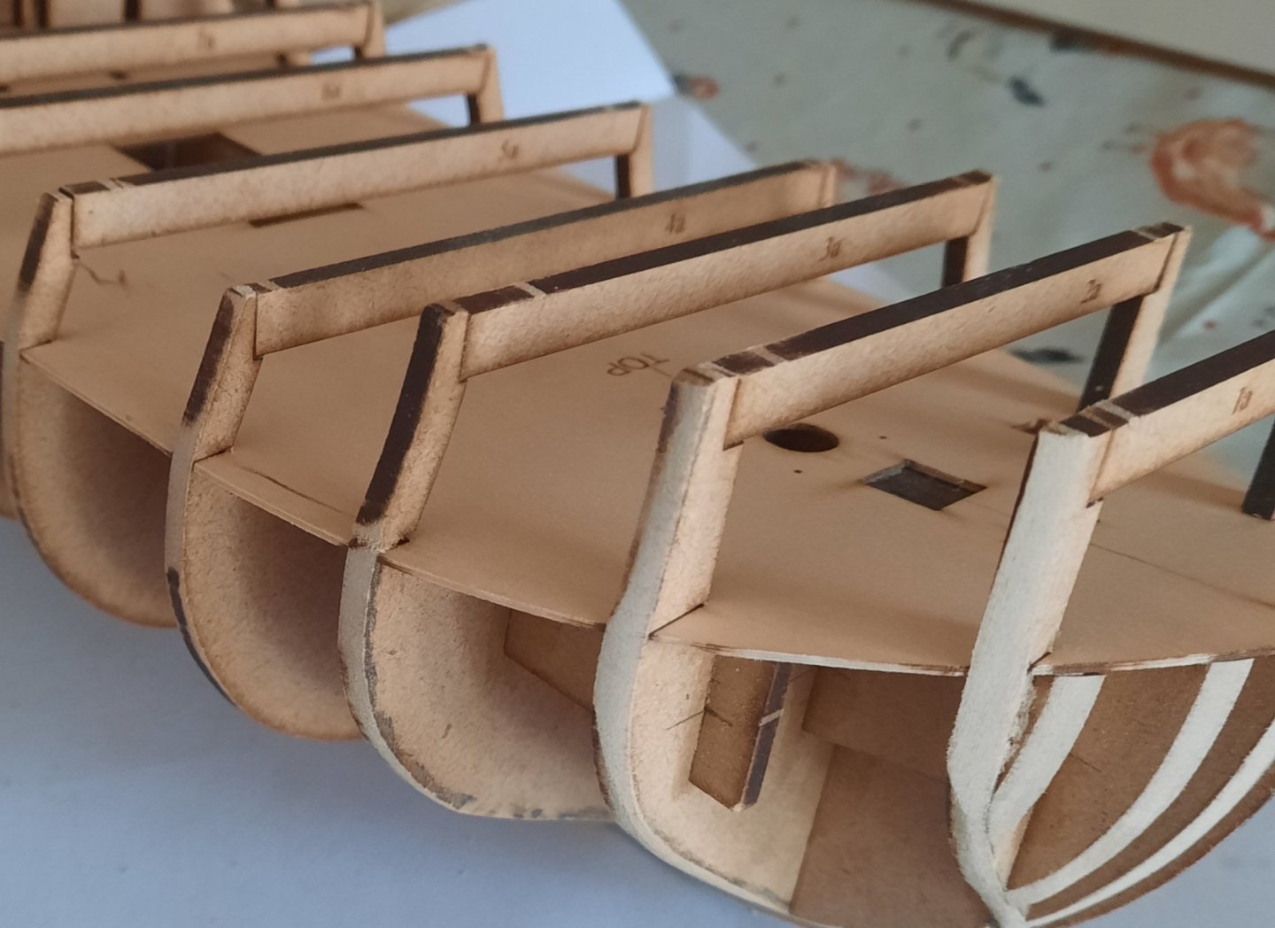
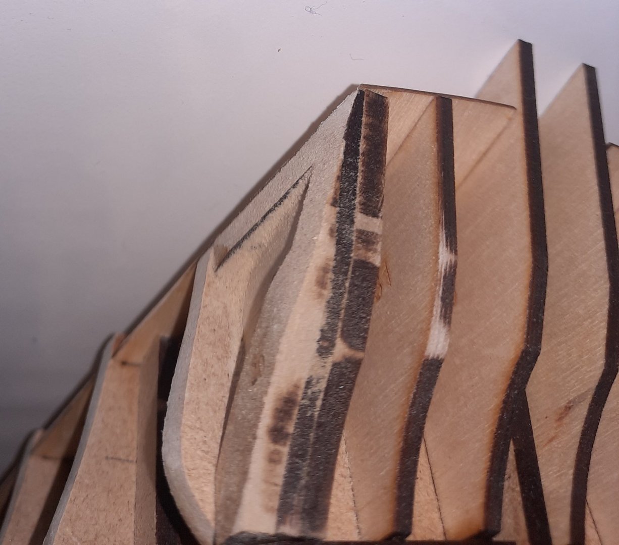
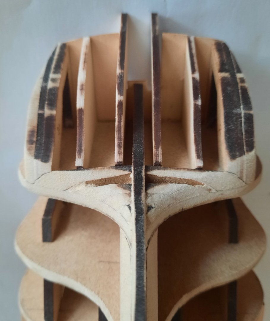
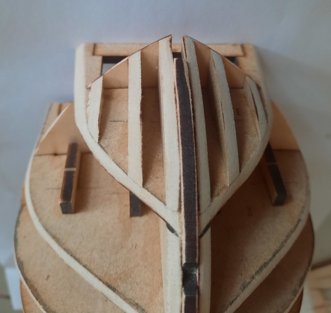
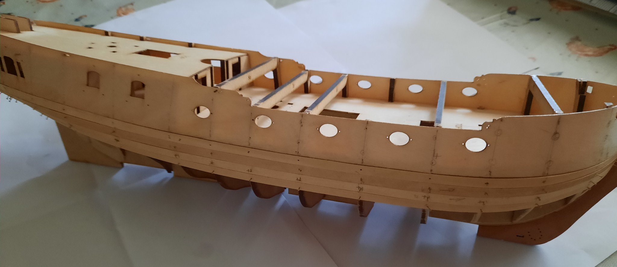
Stage: Hull Construction Build instructions: 60 - 66 Task: Fairing of the hull Parts: N/A Time Spent: 240 mins Status: Complete Build Notes: I took my time with this task. I used a mixture of my standard and thin Flory standing sticks and 220 grit sandpaper. I found it necessary to check the fairing with some planks, especially where the deck and bulkhead meet and at the stern area where patterns 19, 19a, 19b and 19c are fitted. I lost count of the times I thought it looked OK only to discover a plank would not lay true over between bulkhead 12 and 13 and around the stern patterns (19, 19a, 19b and 19c). I also found checking the fairing with my illuminated magnifier to be beneficial, especially for the bow area for bulkheads 1 to 3 and bow pattern 15. After about 4 hours work I was finally happy with fairing and I think the hull is now ready for the next stage of the build process which will be to add the bow pattern (49) and to bend the two bulwark patterns (45). Due to the nature of the pear wood it is essential that the bulwark’s, which will be soaked in hot water for approx. 30 mins) are allowed to fully dry out during the bending process as this type of wood does expand when wet and will return back to its original size once it has fully dried out. Build Photos Outer Stern Pattern 20 Stern Patterns Bow Area Bow Bulkheads Stern Bulkheads
- 382 replies
-
- 10
-
-
- Vanguard Models
- Duchess of Kingston
- (and 1 more)
-
Thanks Chris. It is a slow process with plenty of checks as I progress to make sure I have faired enough at each key point. James did provide me some useful advice as well.
- 382 replies
-
- 1
-
-
- Vanguard Models
- Duchess of Kingston
- (and 1 more)


.jpg.0bbe8f1a7dd0ebe1d8556357a7a7a41b.jpg)