HOLIDAY DONATION DRIVE - SUPPORT MSW - DO YOUR PART TO KEEP THIS GREAT FORUM GOING! (89 donations so far out of 49,000 members - C'mon guys!)
×

archjofo
-
Posts
1,498 -
Joined
-
Last visited
Content Type
Profiles
Forums
Gallery
Events
Everything posted by archjofo
-
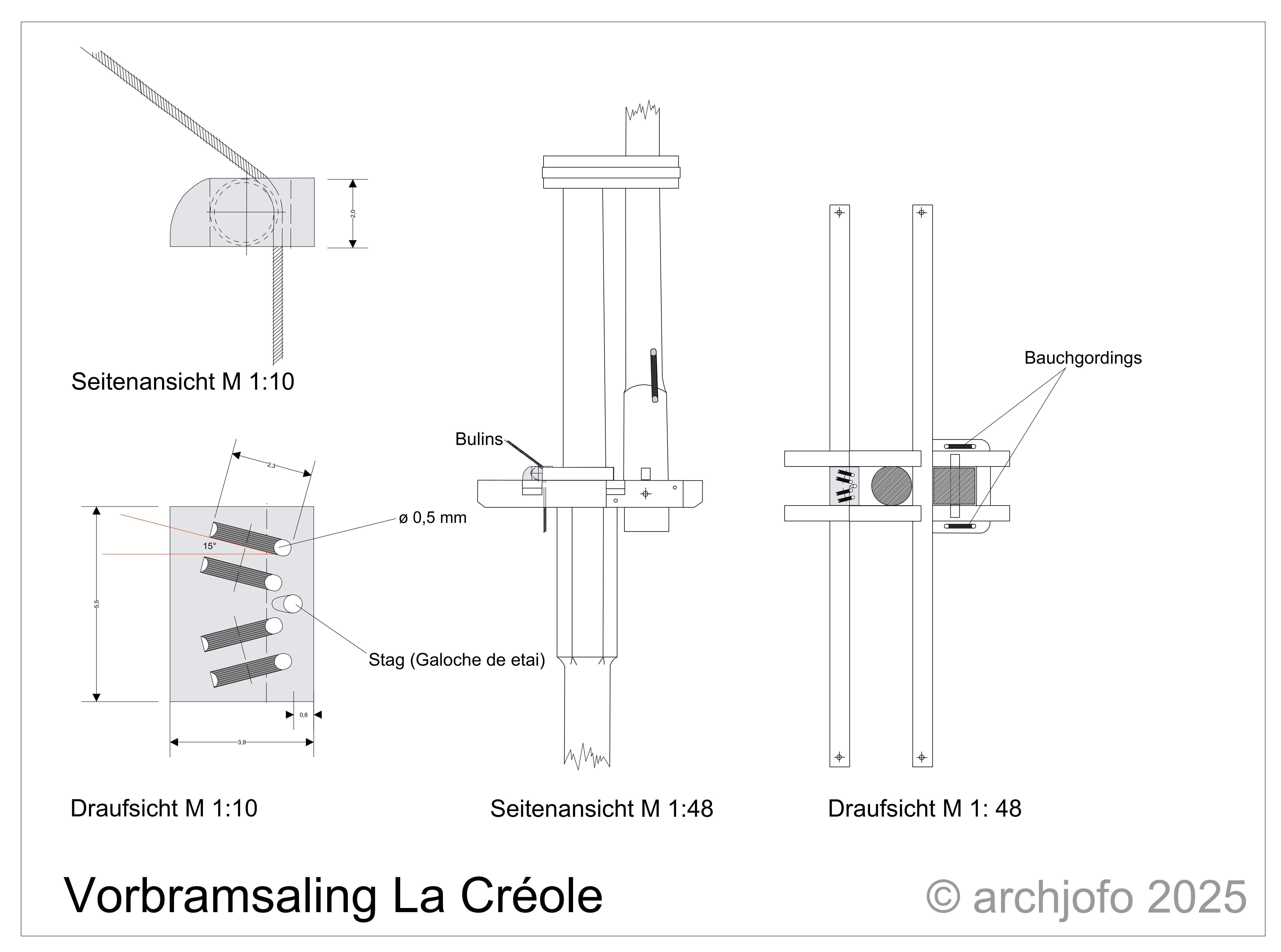
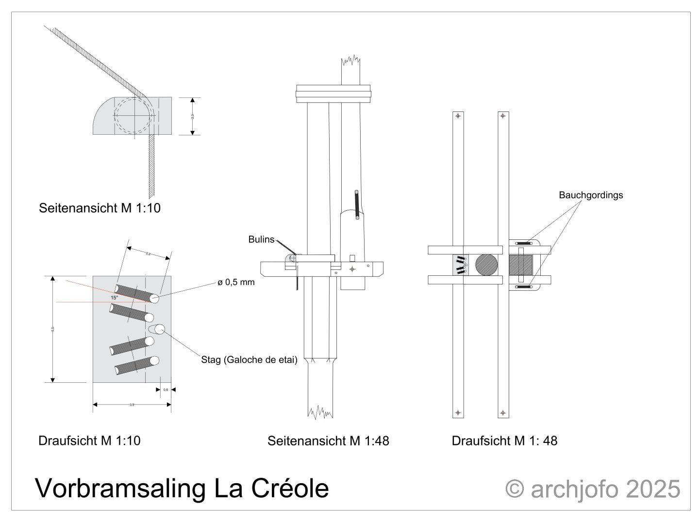
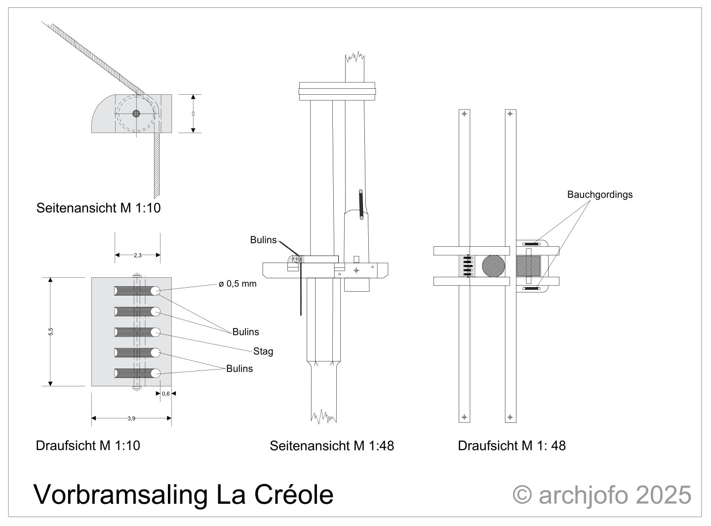
 @Dowmer Hello, Obviously there were two possibilities, as can be seen on the two extracts from the atlas. Basically, I think it is irrelevant whether the guide hole for the stay is at the front or rear. As long as the hole is in the centre, there is no crossing with the bowlines. In this respect, I orientated myself on the original La Creole model. There the stay faces the topgallant mast. I hope I have expressed myself clearly.
-
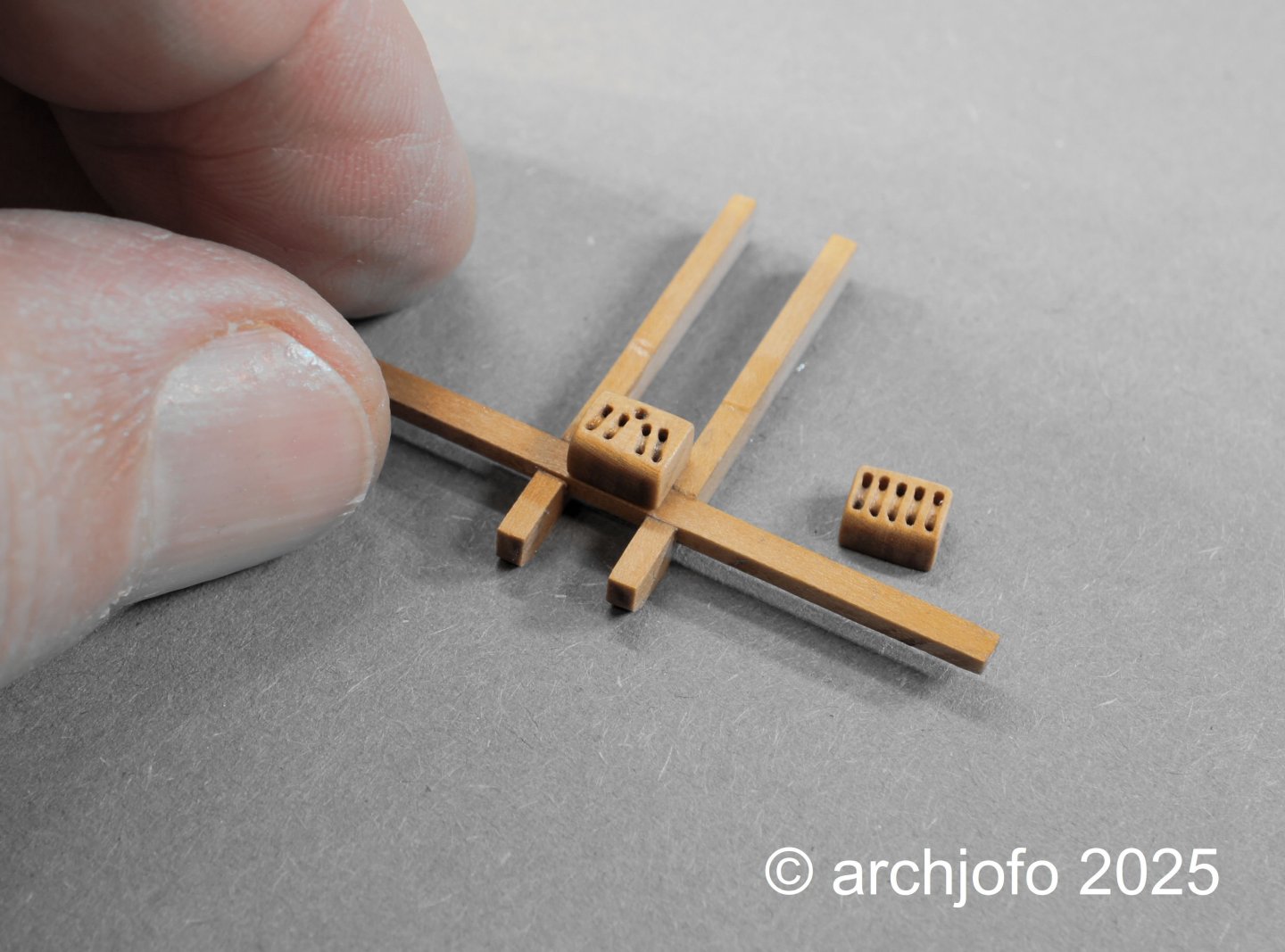
Continuation: Guiding the bowlines for the main topgallant sail and the main royal sail Here I will show the implementation of the detail for the model of La Créole on a scrap part, as it will be put on later. Next to it is the version of the previous version. As already mentioned, I need an analogous part for the deflection of the bowlines of the mizzen royal sail and the braces of the mizzen royal yard, which is then to be mounted in the rear area of the main topgallant cross trees. Theoretically, I should now be done with the running rigging and have recorded all the blocks that are needed without sails. Many blocks are already attached to the individual yards with the corresponding ropes, as far as it makes sense. Before I take the corvette out of "exile" (dust cover), I will go through all the rigging again and clean the workroom of dust. Then I can finally start with the final rigging. To be continued...
-
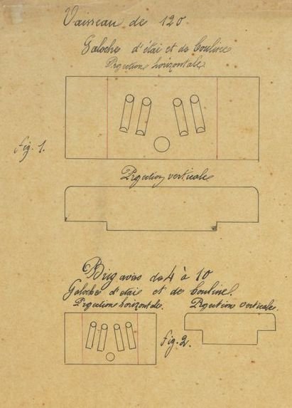
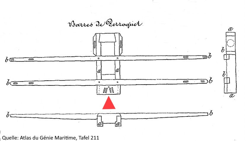
Continuation: Guiding the bowlines for the main topgallant sail and main royal sail After four discs were arranged in the appropriate position in the illustration in Atlas du Génie Maritime, Plate 211, I still had to clarify how to proceed with the main topgallant stay. As I remembered having saved other sheets of the Atlas du Génie Maritime on my computer a long time ago, I looked there again for relevant details and the following came to light: Source: Excerpt from Atlas du Génie Maritime This detail was obviously used for larger (Fig. 1) but also for smaller ships (Fig. 2). As is clearly evident from the description, the four disc gates are reserved for bowlines and the guide hole for the topgallant stay (galoche d'etai). After this clarification, I modified my drawing and can then move on to implementation. To be continued...
-
Continuation: Guiding the bowlines for the main topgallant sail and the main royal sail A model building colleague made a suggestion for the guidance of the bowlines. So I researched the arrangement of the discs again and saw an important detail in the Atlas du Génie Maritime. I have looked at plate 211 many times, but only found this interesting detail after a targeted search. So I will modify the alignment of the discs accordingly. Many thanks again to Robbi for the suggestion.
-
Continuation: Guiding the bowlines for the main topgallant sail and the main royal sail Thankfully, I received a photo of the rear area of the fore cross trees from a nice restorer at the Musée de la Marine in Paris. There you can see the routing of the bowlines of the main topgallant sail and the main royal sail. As already described, I assume that discs were actually used here to redirect these ropes. It is also clear from the photo that the main topgallant stay was also guided over them. Accordingly, I made a drawing of how this wooden part might have looked from my point of view, and thus functionally meets the requirements for a good and safe redirection. I will try to make the part like this. To redirect the bowlines for the mizzen royal sail and the braces for the mizzen royal yard, an analogous part is needed for the rear area of the main cross trees. To be continued...
-
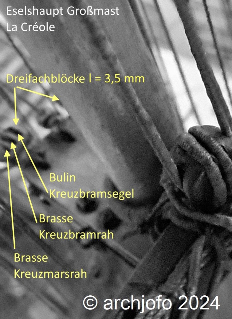
@wefalck Hello Eberhard, yes, I am very pleased that the ladies have so much patience with me. If you ever meet them again, it would be nice if you could give them my heartfelt thanks again (I have already done so several times by email). @jdbondy Hello JD, Thank you for your interest and comment. @dvm27 Hello Greg, Thank you very much for your positive comment. I also see the chaffing and the increased effort of replacing the ropes as a problem. This can be counteracted with discs. @shipmodel Hello Dan, Thank you in advance for your interest and support of my work. In my opinion, the guidance of the bowlines cannot be compared to that of yard halyards. The bowlines are always moving, whereas the yard halyards are static and are therefore subject to increased friction. As already shown, there are proven examples of the bowlines being redirected with discs, see my post in #2357. What further suggests that this is a simplification of the original model is shown in the following image section of the fore topgallant yardarm. There, too, there is only a hole instead of a disc. Source: La Créole Musée de la Marine in Paris What I have already written about this and these further thoughts lead me to believe that discs were used here.

-
Addition: Guide of the bowlines for the main topgallant sail - and the main royal sail Today I received a few photos of the fore crosstree from the original model of La Créole for the guide of the bowlines for the main topgallant sail and the main royal sail. Thankfully, a nice restorer from the Paris Marine Museum went to the depot and took the relevant photos at my request. Here is one of these photos with a direct view of the rear area of the cross tree. As expected, you can see a wooden attachment for guiding the bowlines. You cannot see discs for deflection here, presumably the ropes are simply led through a hole. I think that discs were used in the original here, and that the model is probably a simplification by the model maker at the time. Whether wrong or right, in any case I am making an assumption and will try to implement this detail with discs.

-
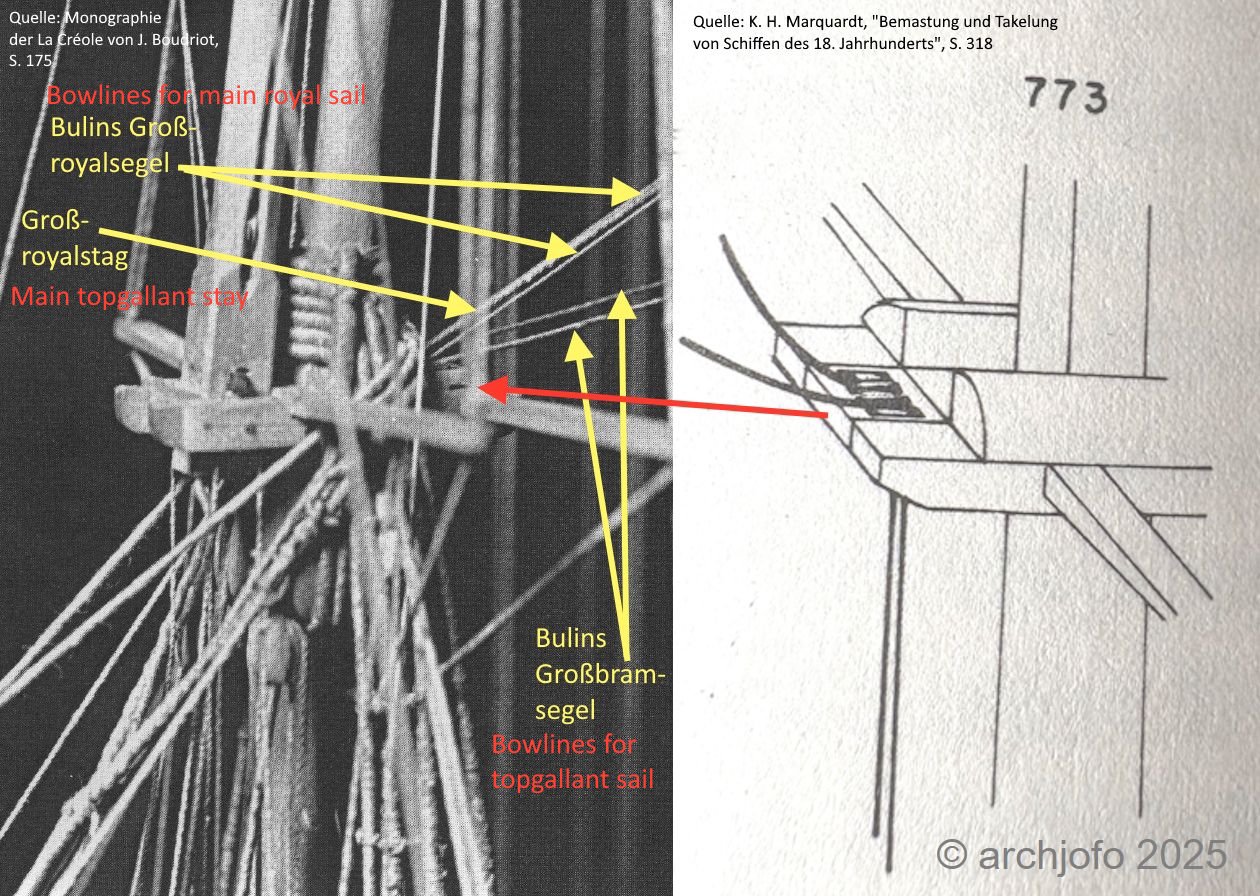
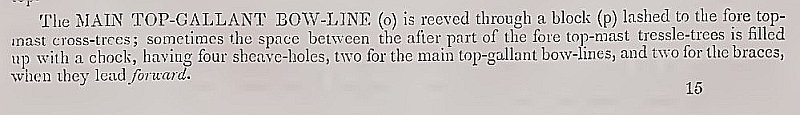
@Wishmaster Thank you very much for your praise, it makes me happy and motivates me. But I also don't want to miss the opportunity to thank everyone else for the LIKES. Continuation: Guiding the bowlines for the main topgallant sail - and the main royal sail Following a tip from a model-building colleague, I was able to find the following in K. H. Marquardt's book "Mastung und Takelung von Schiffen des 18 Jahrhunderts" on the question of the guidance of the main topgallant bowlines and the main royal bowlines: This is how I interpreted the hidden detail in the image section of the fore cross trees of the La Creole. Since Marquardt referred to Darcey Lever in his illustration, I did some more research and found this: In his book "The young sea officer's sheet anchor; or, A key to the leading of rigging, and to practical seamanship" you can read that sometimes the space between the rear trestle trees was filled with a piece of wood in which there were 4 discs. Two for bowlines and two for braces, as long as they came from the front. In the case of the La Creole, however, there would be four bowlines. Now I will think about how I should design this detail. Unfortunately, I haven't heard back from the museum in Paris yet. Best regards
-
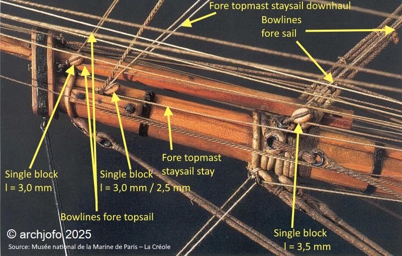
Continuation: Further blocks in the area of the bowsprit There was uncertainty about two ropes. In this context, I then researched the fore topmast staysail stay in detail in the documents available to me. I included the advice of fellow model makers in my considerations. So I investigated the possibility of whether a fore topmast staysail stay was rigged on the La Créole. As so often, I found crucial information in the book - The Model of the Brigg Irene - by E. W. Petrejus. At the beginning of the 19th century, few staysails were set on the stays, but instead were used on staysail stays and preventer stays. Accordingly, I have come to the conclusion that it was quite possible and probable that a fore topmast staysail stay was rigged on the La Créole and have therefore added the explanations of the image section. Unfortunately, I have not yet received a response from the restorer at the Paris Marine Museum regarding the bowines for the main topgallant sail and the main royal sail. I hope something will come of it. See you then...
-
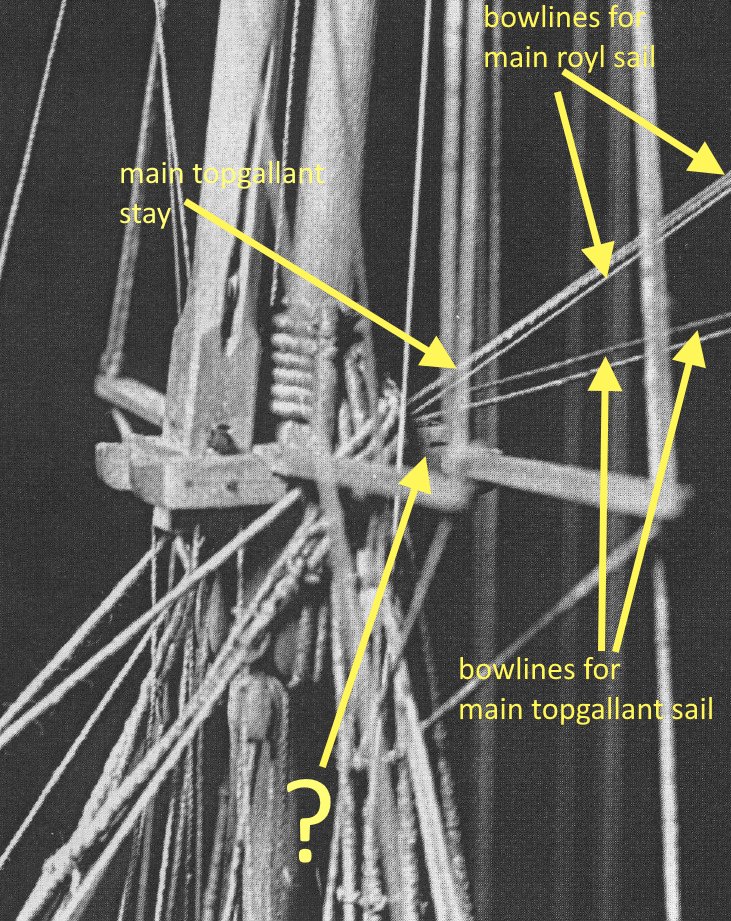
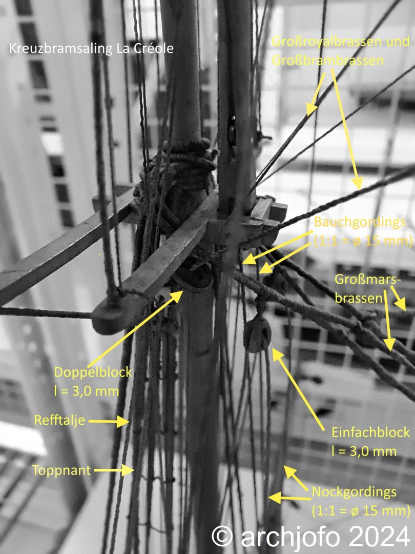
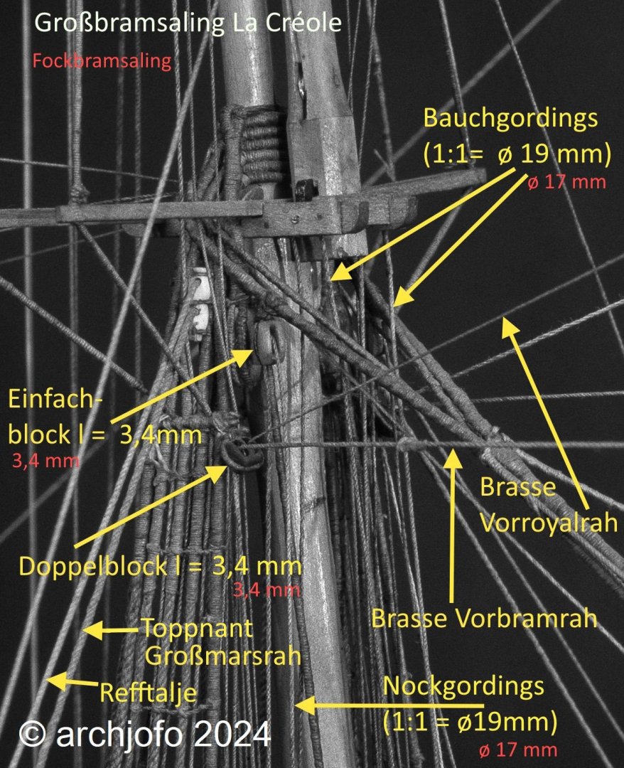
Guiding the bowlines for the main topgallant sail - and the main royal sail During the further detailed coordination in the upper levels of the rigging for my French corvette, it had to be clarified how the bowlines for the main topgallant sail and the main royal sail should be deflected in the rear area of the topmast crosstree. In the monograph on La Créole by J. Boudriot, deflection blocks are indicated. However, further concrete details are not apparent. I therefore tried to clarify this detail by taking photos of the original model. Unfortunately, I was unable to find any useful illustrations. Only the monograph contains a photo of the topmast crosstree (see picture). In addition to the main topgallant stay, the bowlines for the main topgallant sail and the main royal sail are clearly visible. However, the deflection of the bowlines is not clearly recognisable. It appears to be a rectangular crossbar with integrated discs, at least in my opinion. Source: Monograph on La Créole by J. Boudriot It is certain that these are not blocks, which would be usual for this purpose. As I was unable to find anything else on this subject, neither in the relevant specialist literature nor on the Internet, nor on original models from a comparable period, I will contact the restorers at the Paris museum. A very friendly lady has already helped me a lot. But perhaps one of you has already come across a similar detail. I would be very pleased to receive any relevant information. See you soon ...
-
@albert I am very pleased and grateful for such nice comments. Of course, professional advice and comments, even critical ones, are also welcome. Nobody is perfect and life is a constant learning process. Here are some more details: Additional blocks, including in the area of the topmast crosstrees I should have recorded most of the blocks for the La Créole by now. The blocks in the area of the topmast crosstrees and on the mainmast cap still need to be made, as can be seen in the following pictures. These are blocks for guiding leech lines, braces and bowlines. When guiding the braces for the mizzen topgallant yard, I am following the Paris model, where they go to the mainmast cap. The variant shown by J. Boudriot in the monograph, guiding the braces to the main topmast crosstrees, seems less practical to me for stability reasons on the high-rigged corvette. In addition to making these blocks, I am currently still trying to figure out which blocks I still need for the upper area of the rigging on the royal topgallant crosstrees. I don't think there will be too many left. To be continued... Feedback geben
-
Another excellent performance. The boat is impressively beautifully executed.
-
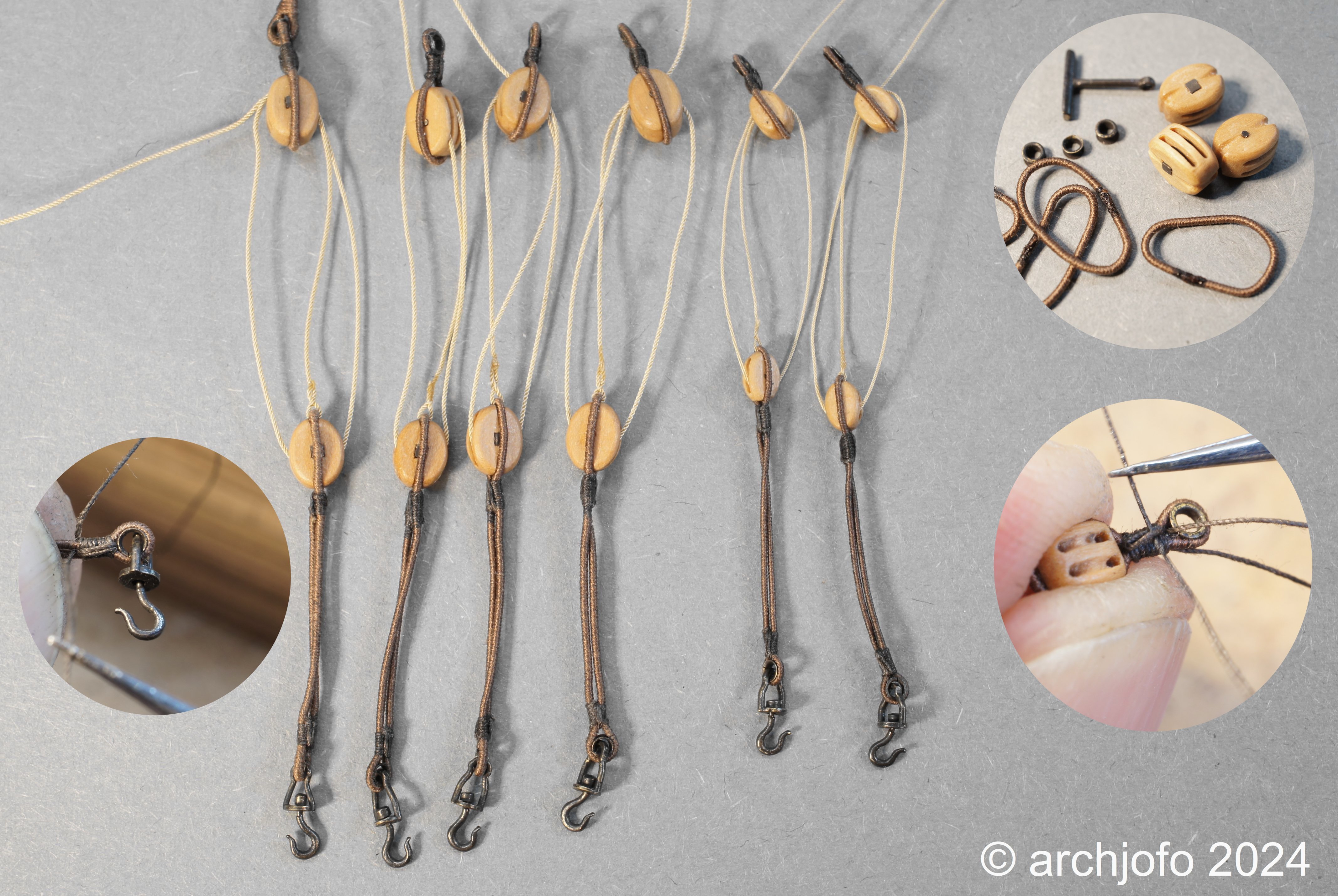
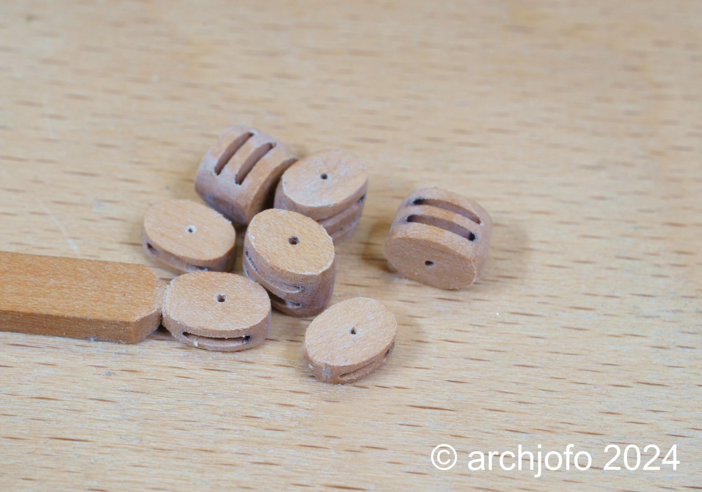
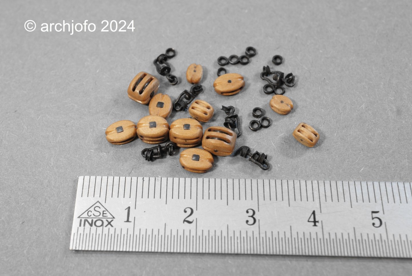
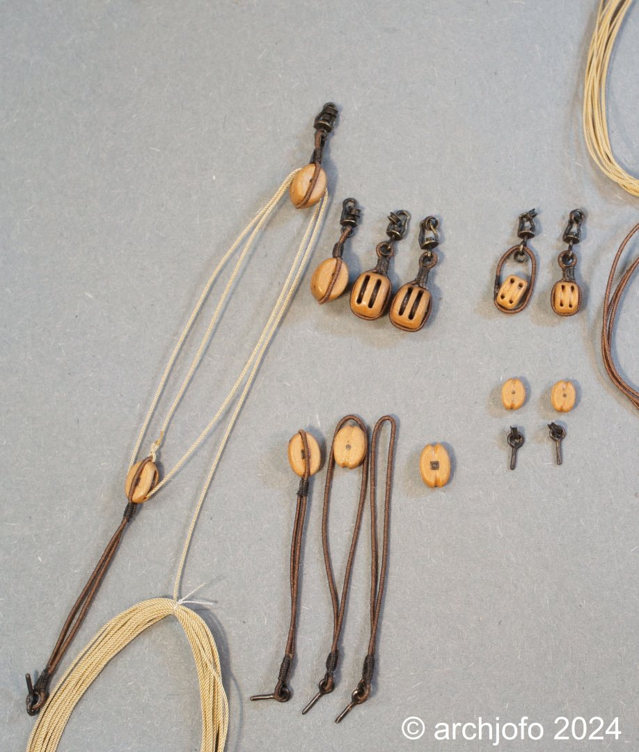
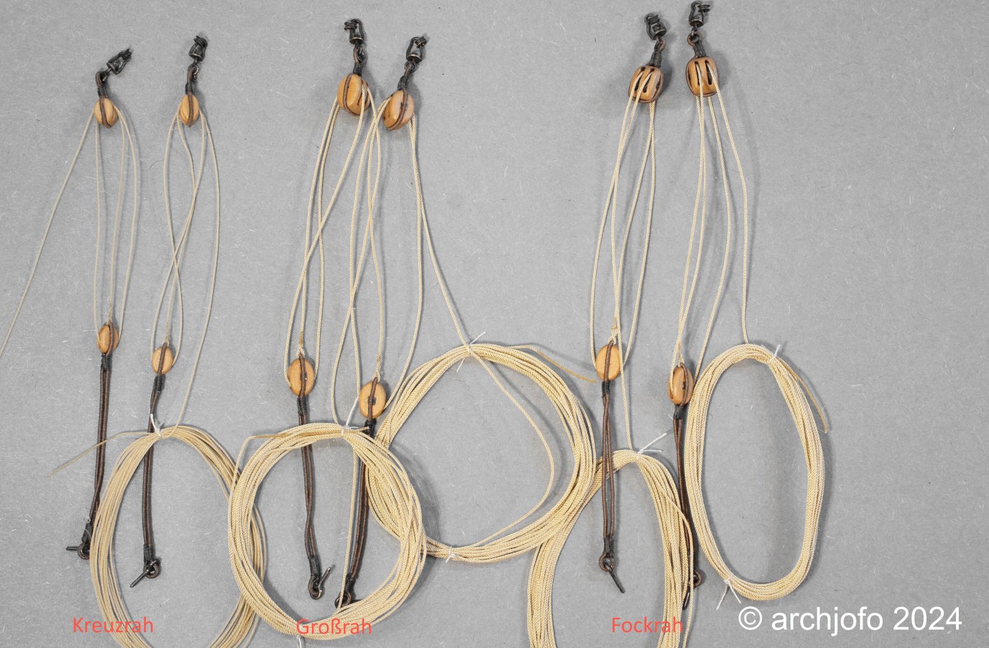
@Keith Black @MarcM Thank you very much for your support. Thanks to everyone else too for the LIKES. Completion: Addition of the lifts of the lower yards - Balancines de basse vergue As I wrote before, I always make the blocks based on a theme, such as here for the tackles of the lifts of the lower yards. Among other things, this ensures that I produce exactly the required quantity in the required size and thus do not produce excess capacity. This also keeps you motivated and does not become monotonous, which can ultimately take away your desire to craft. However, this does not necessarily work for everyone. Accordingly, I made 4 double blocks with a length of 5.6 mm, 4 single blocks with a length of 5.6 mm, 2 double blocks with a length of 4.0 mm and 2 single blocks with a length of 4.0 m. I have already described the method of making the blocks many times in my construction report. A few pictures are below. After making the eyebolts with thimbles for attaching the tackles to the rigging, I was able to tie the single blocks into block strops and add the tackle ropes. The last picture shows the finished tackles for the lifts of the lower yards. We will continue in the new year with the last blocks in the area of the topgallant masts.

-
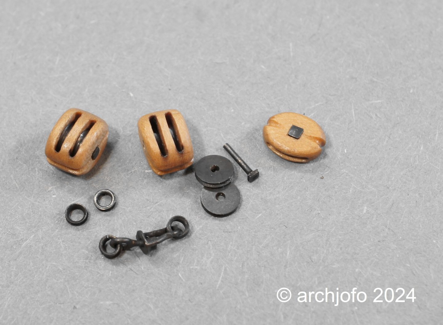
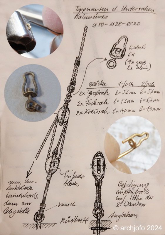
@Keith Black Thank you for your nice comment. Continuation: Addition of the lifts of the lower yards – Balancines de basse vergue In the last post I described why and how I will carry out the tackles of the lifts from the lower yards. I have drawn a corresponding sketch for this. First I made a swivel for this, as can be seen in the following picture. It was made in the same way as the swivel hooks for the topsail halyards. Two opposing notches are filed into a brass disk d = 0.3 mm with a ø 2.3 mm and a bore ø 0.8 mm, which then accommodate the ø 0.4 mm thick brass bow wire for soldering. The eyebolt is secured so that it can rotate freely with a soldered brass sleeve. Next, the double and single blocks for the tackles have to be made. I will again equip the larger blocks for the lifts of the main and fore yard with real disks. At this point I would like to wish you all a Merry Christmas and a good start into the New Year!
-
Hello Tim, this will be a very nice model. Here you can see how a fake splice is made. Follow the LINK.
-
@dvm27 Hello Greg, I'm extremely pleased that such a profound and excellent model maker sees it the same way as I do. In 150 years there probably won't be much left of the silk rigging. But since I have documented everything in detail, the model could be easily restored ... 😉
-
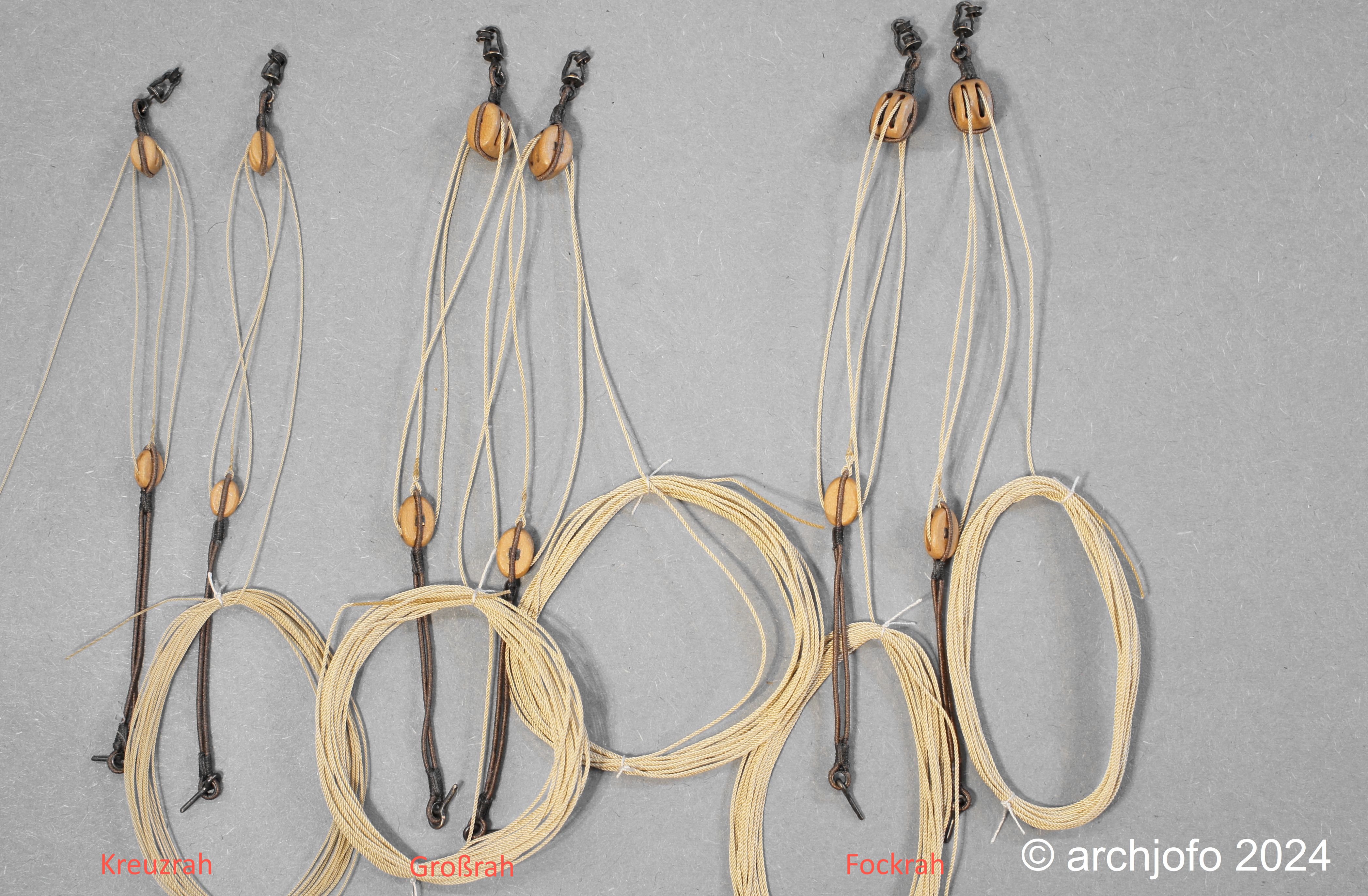
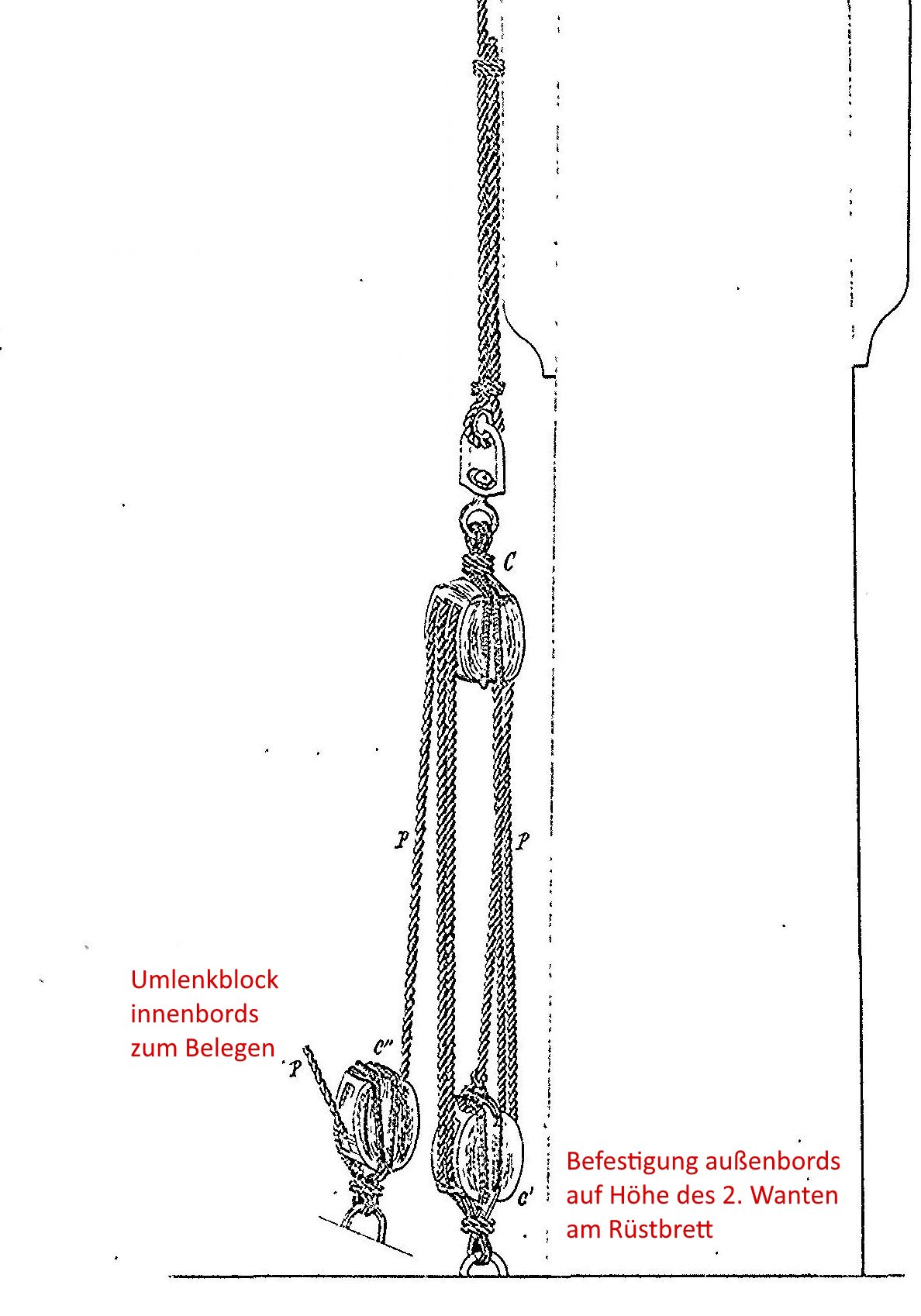
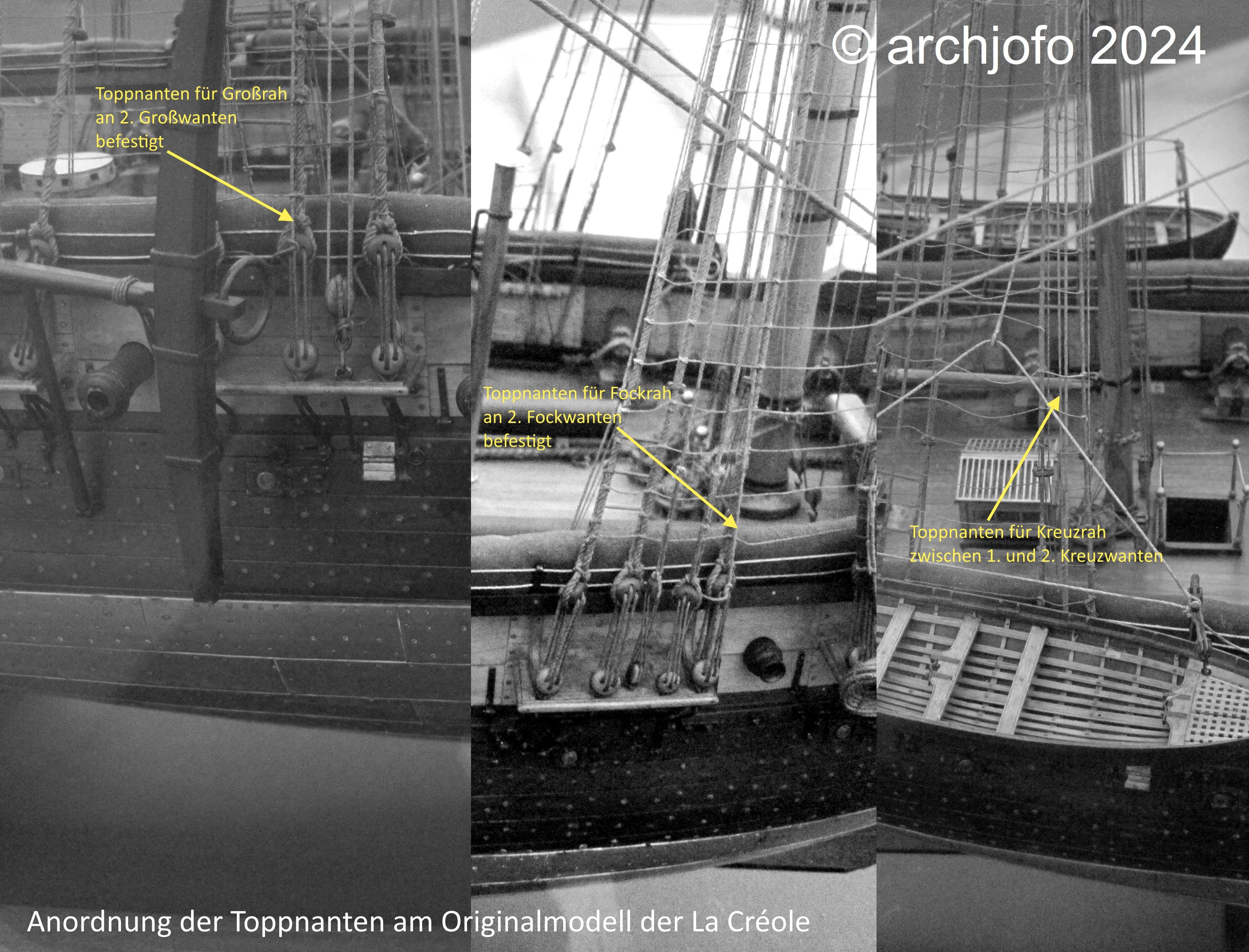
Addition of the lifts of the lower yards - Balancines de basse vergue Usually, as can be read in the specialist literature in the book "Manuel de gréement" by F. A. Coste, Paris 1829, the lifts of the lower yards were secured using tackles, each at the height of the 2nd shroud of the respective lower mast. This is also how J. Boudriot illustrated it in the monograph on La Créole, as shown below. Source: Monograph La Créole by Jean Boudriot On the original Paris model, I identified the lifts as shown in a diagram: Source: Musée national de la Marine de Paris - La Créole However, no tackles can be seen there. The lifts were simply attached to the upper part of the tackle ropes at the height of the 2nd shroud. This easier handling of the lifts could have been due to the size of the ship, or is it a simplification by the contemporary model maker? We will never be able to find out. However, I find this type of seamanlike handling of the lifts rather impractical and have therefore decided to use tackles, whose ropes can then be properly secured on the inside. I wouldn't exactly describe my model as a "pile of evidence" as a dear forum colleague once described his project. However, I have implemented a large number of details on the model that seemed plausible to me after research. I cannot provide 100% proof of this, but solutions that actually existed and generally fit into the temporal and country-specific context of La Créole. In this respect, I will basically attach the lifts as follows: Source: Excerpt from Atlas du Génie Maritime annexe N.1, Pl. 20 However, I will only use a double block at the top and a single block at the bottom for the tackle. To be continued...


-
Hello colleagues, Today I would like to thank you all for the positive reactions to my last video. Because of my son's house construction, which of course requires a lot of my time as a retired architect, I have hardly had time to do any model building lately. So I at least enjoyed putting together a video. But things will continue here soon...
-
@matiz Hello Tiziano, thank you for your nice comment. I'm particularly pleased to receive such praise from such a fantastic model maker. Of course I would also like to thank everyone else for the LIKES. Hello fellow model builders, today I would like to present to you my new video about the yards and spars of the La Créole. I hope you enjoy it: LINK
-
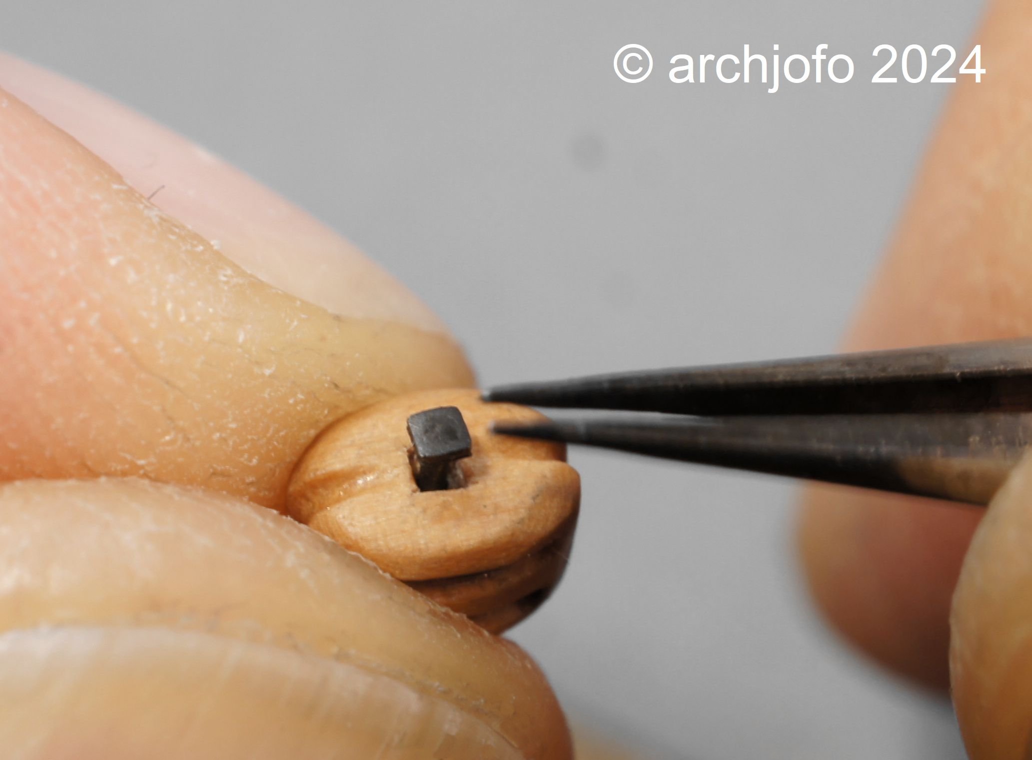
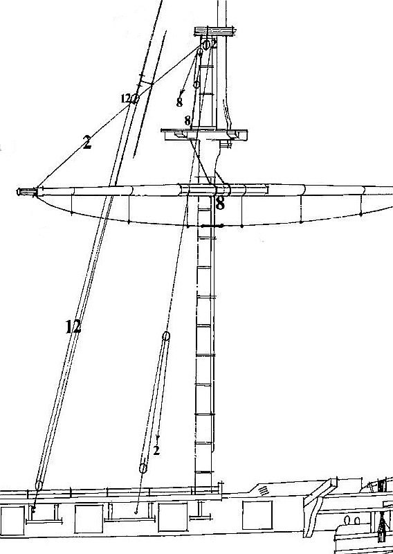
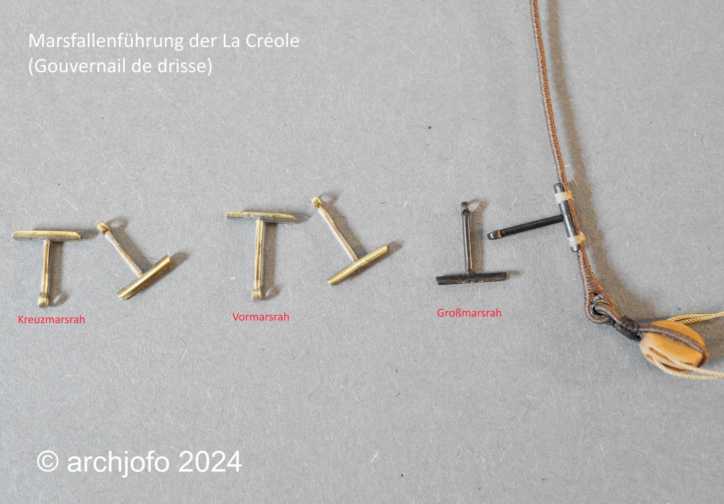
@albert @64Pacific Thank you for your interest and the nice comments, and thank you all for the LIKES. Topsail-halyard traveller – Gouvernail de drisse There was something else, wasn't there? I have now made the missing 5 topsail-halyard travelers out of brass to complete the set. To produce the guide rings required for this with a diameter of 1.5 mm (incorrectly indicated in the drawing as 1.2 mm) and with a bore of 0.8 mm, the modifications made (new electric motor with speed control and collets) to my Unimat SL served me very well. I am currently sorting out the continuation of the lifts for the lower yards. See you soon...
-
A small update: Completion: Topsail halyards The tackles for the topsail halyards are now all rigged. See you soon...

-
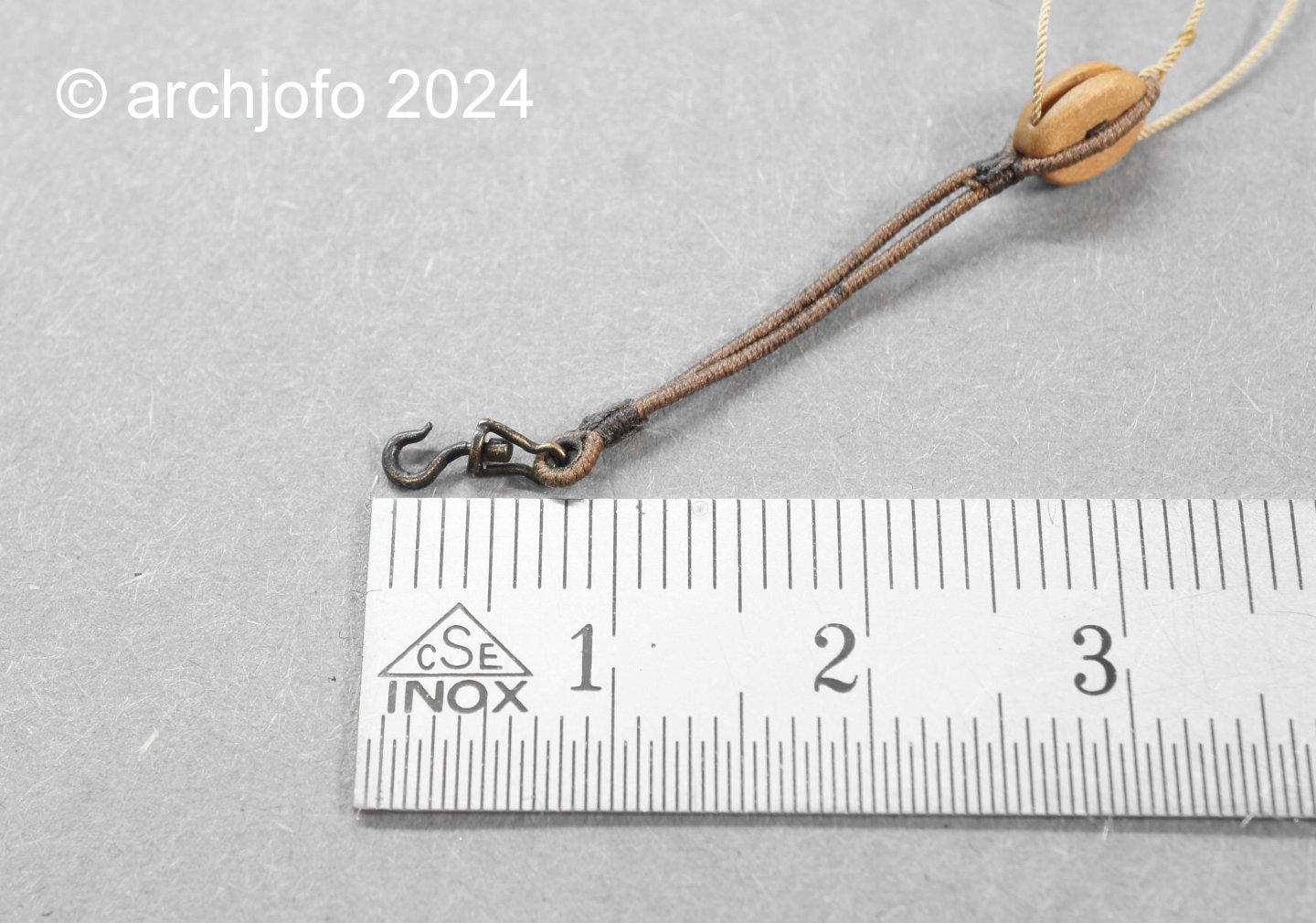
@wefalck Hello Eberhard, I think it would not be a good idea to introduce the French (French publisher) to the rigging practices of the French Navy at the beginning of the 19th century for model making. @Erik W Hello Erik, I'm pleased that my pictures, especially of the rigging work, are helping you with your model building. As I also benefit a lot from pictures and construction reports from other model builders for my project, I want to give something back. It's a give and take that benefits model building as a whole and allows it to develop further. Ultimately, we all have great joy in the results that we have created with our own hands and can look at. @dvm27 Hello Greg, I'm happy to comply with your request. Here is a picture with a ruler: I used two methods to make the thimbles, although I actually only work with the simpler one. I also make the thimbles in different diameters, depending on the requirements of the rigging. Here are two places in my construction report where I report on the production of the thimbles: LINK LINK
-
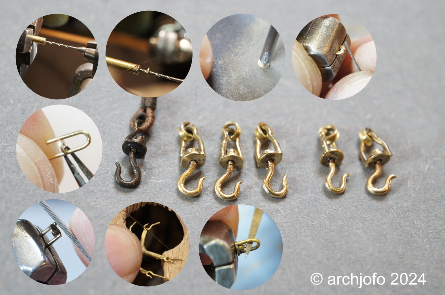
@druxey @Jim Lad @Thukydides @jdbondy Thank you all for your interest. @Thukydides Yes, that's right, the hooks are made of brass. I made some hooks myself out of brass as a sample. A jewelry foundry then created wax models from the samples on my behalf and then cast the hooks using the lost wax process. I hope I was able to explain it clearly. @jdbondy Yes, it's really hard to see in the picture. This is a jeweler's saw that I hold onto the rotating workpiece with a very fine-toothed saw blade. It works very well.
-
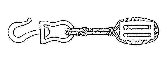
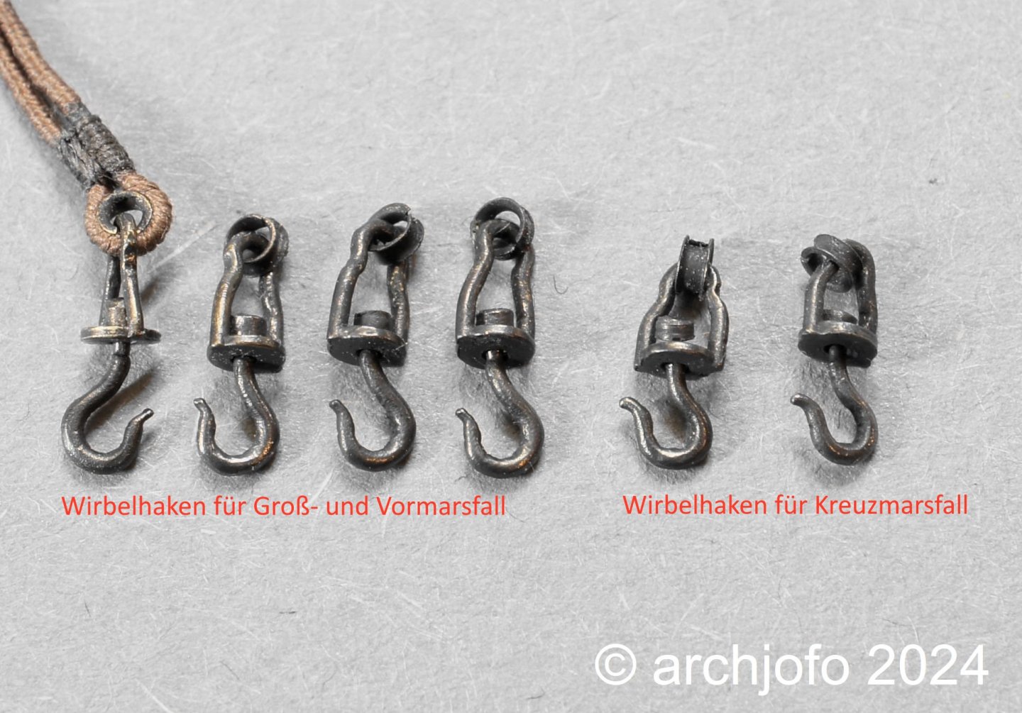
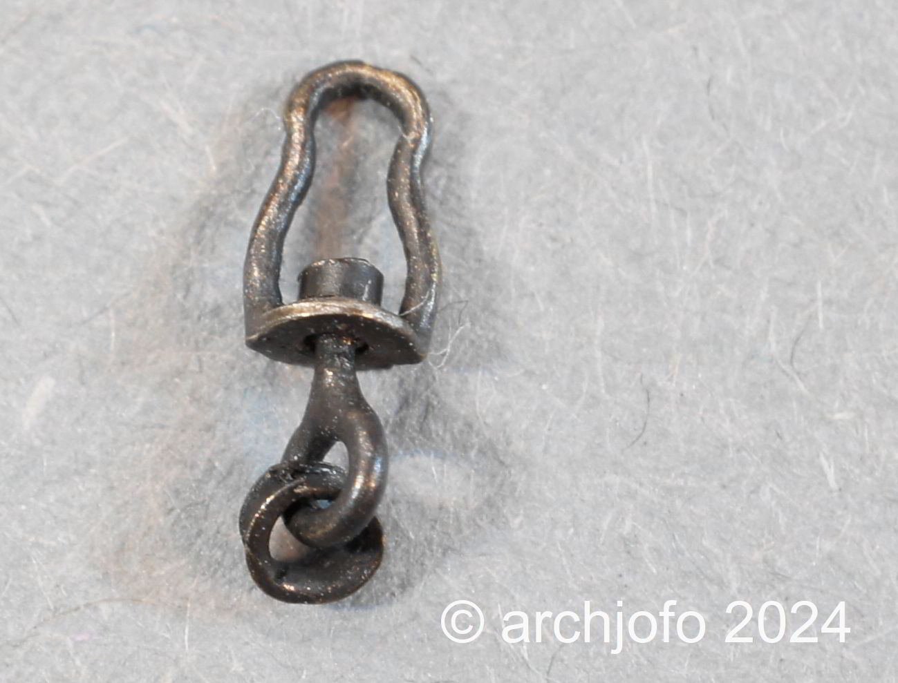
@Thukydides @davyboy @jdbondy @Mike Y Your praise and your kind words encourage me in my work. Thank you for that and thank you to the others for the LIKES. Continuation: Additional accessories for the topsail halyards - swivel hooks In the meantime, I have made all 6 swivel hooks for the topsail halyards. The length for the main topsail yards and fore topsail yards is 8.2 mm. The swivel hooks for the mizzen topsail yards were proportionally made a little smaller (L = 6.9 mm). I tried to make these hooks based on a drawing in the Atlas du Génie Maritime. Source: Excerpt from Atlas du Génie Maritime annexe N.1, Pl. 2 Here, with this photo montage, I would like to illustrate the individual production steps. To conclude this short update, the finished, blackened hooks. See you soon...