HOLIDAY DONATION DRIVE - SUPPORT MSW - DO YOUR PART TO KEEP THIS GREAT FORUM GOING! (89 donations so far out of 49,000 members - C'mon guys!)
×

archjofo
-
Posts
1,498 -
Joined
-
Last visited
Content Type
Profiles
Forums
Gallery
Events
Everything posted by archjofo
-
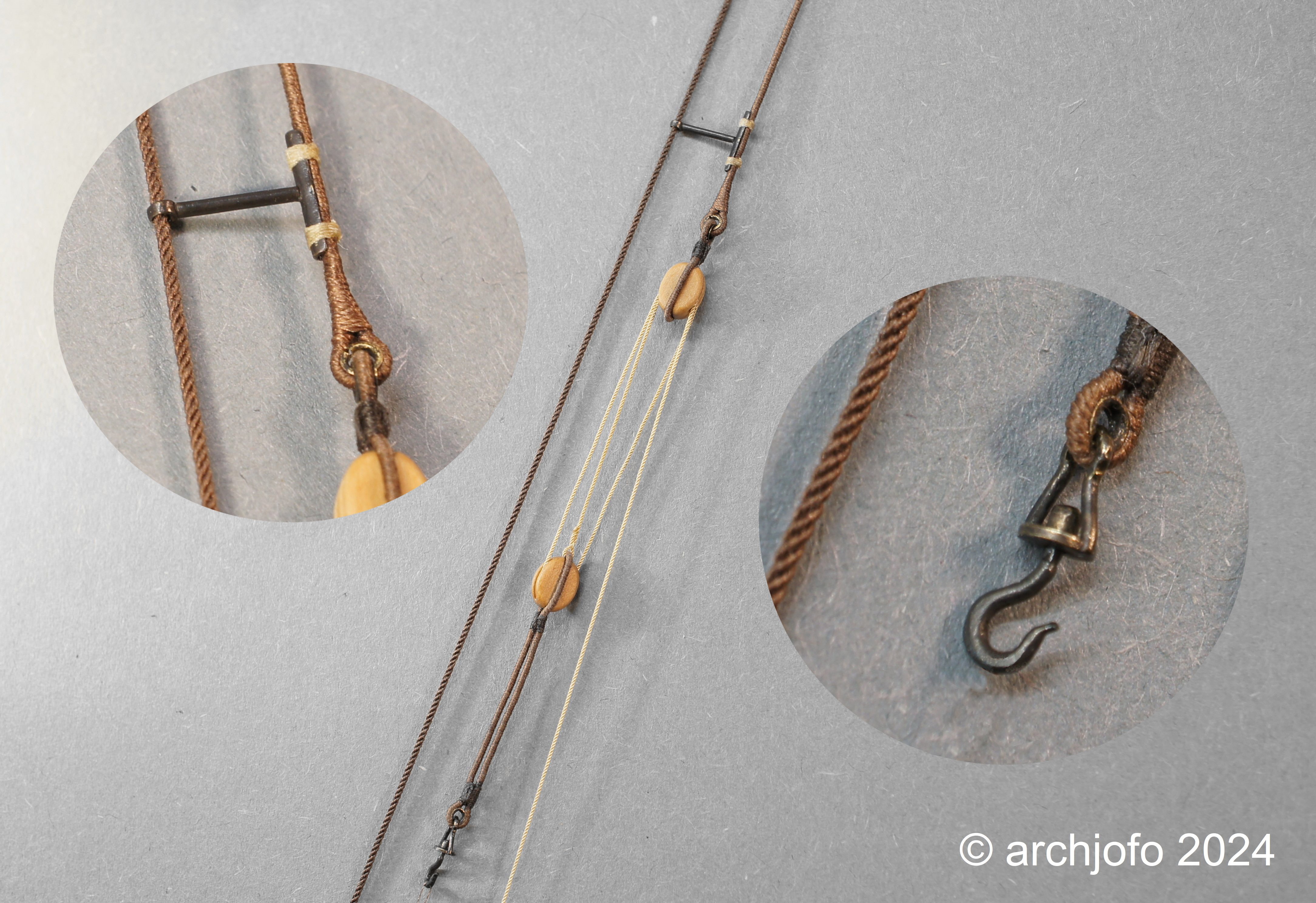
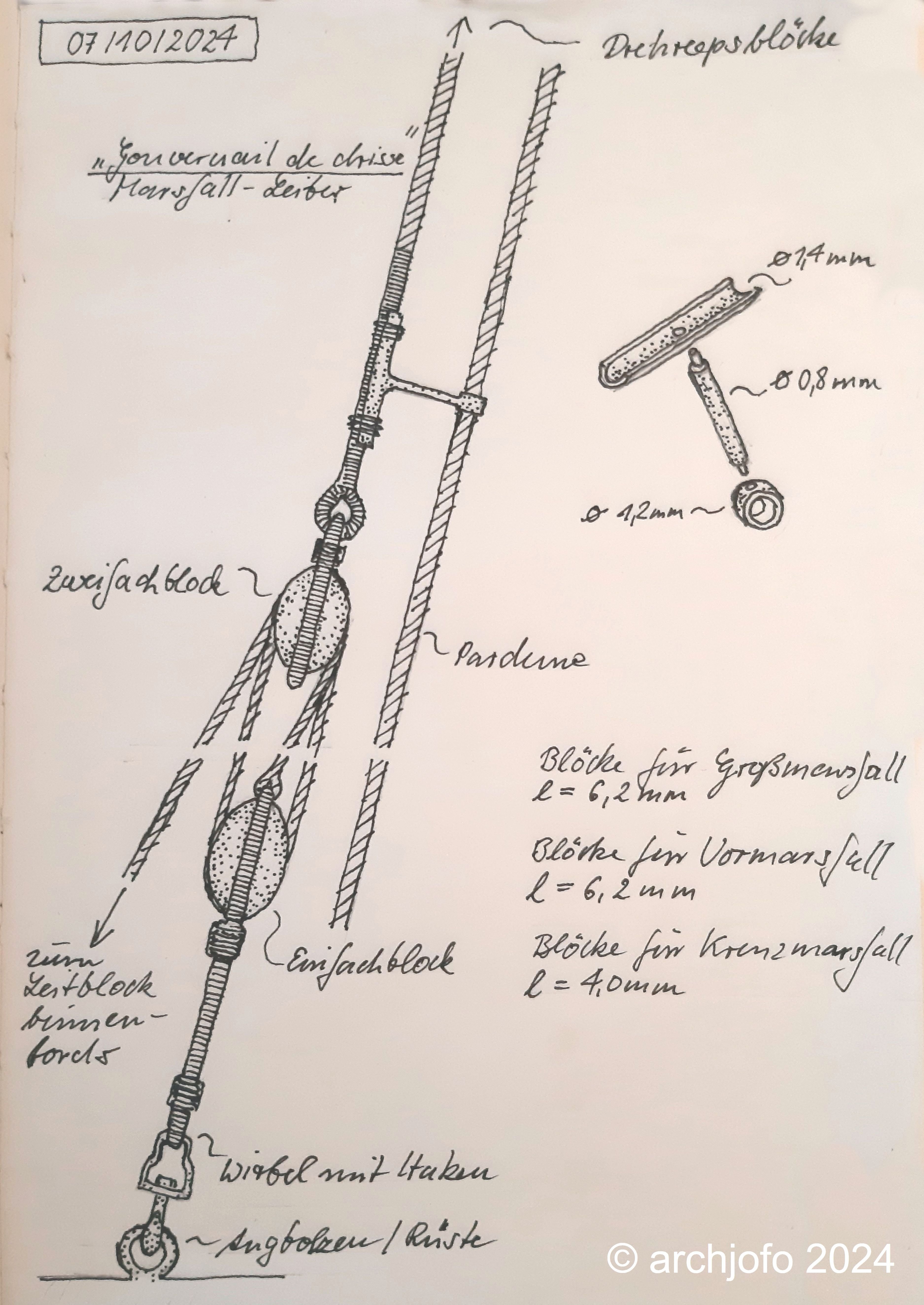
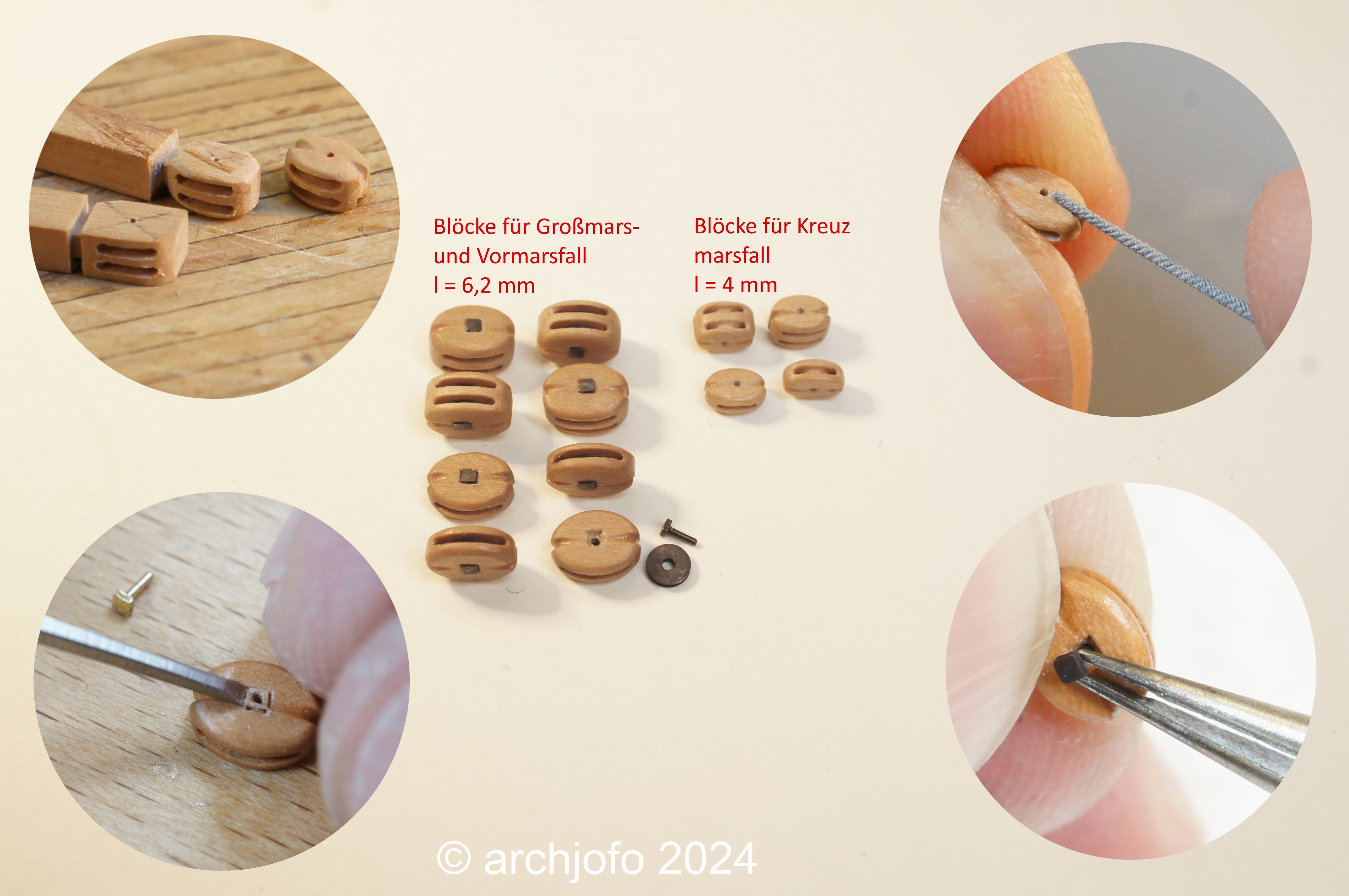
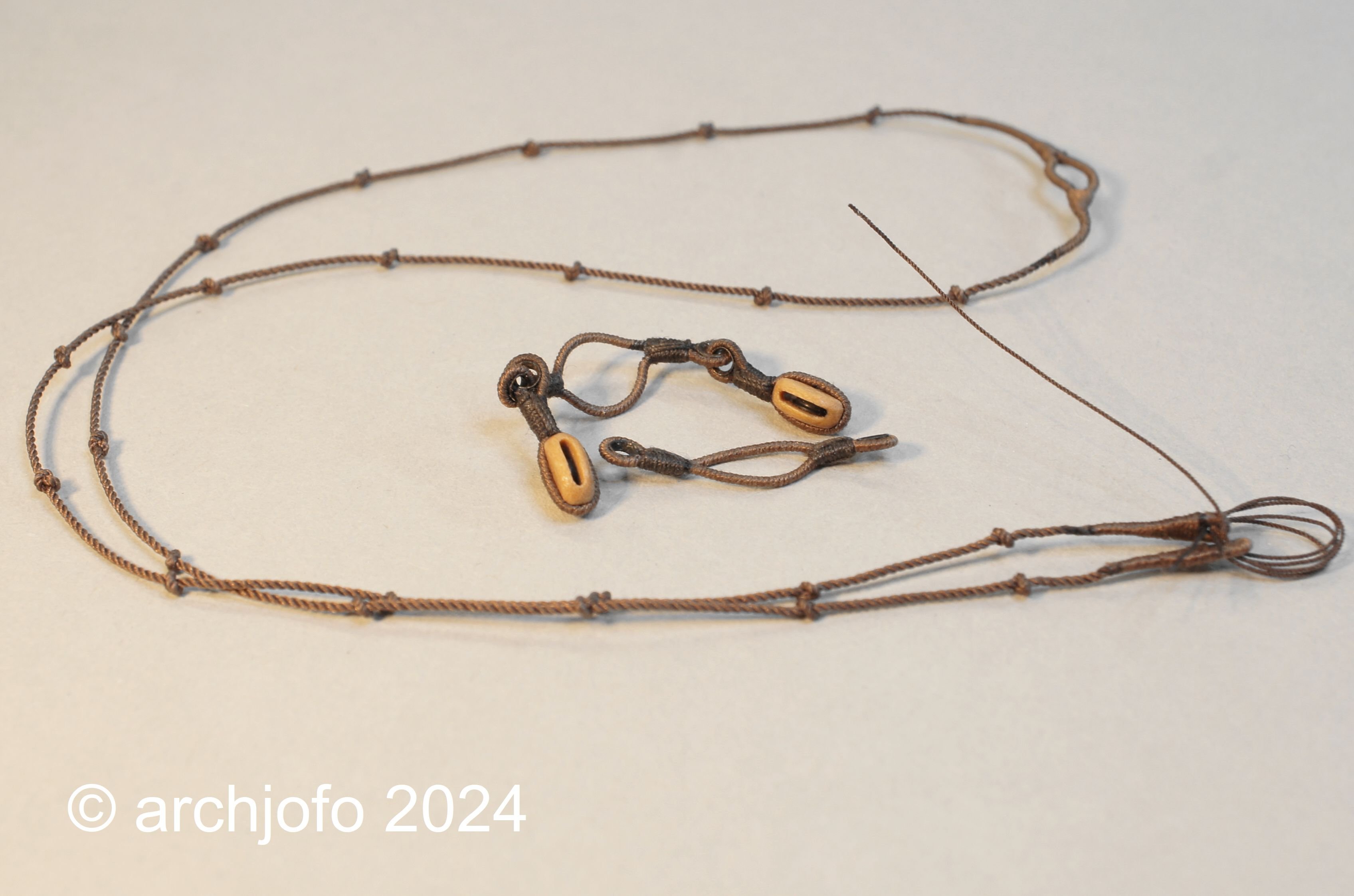
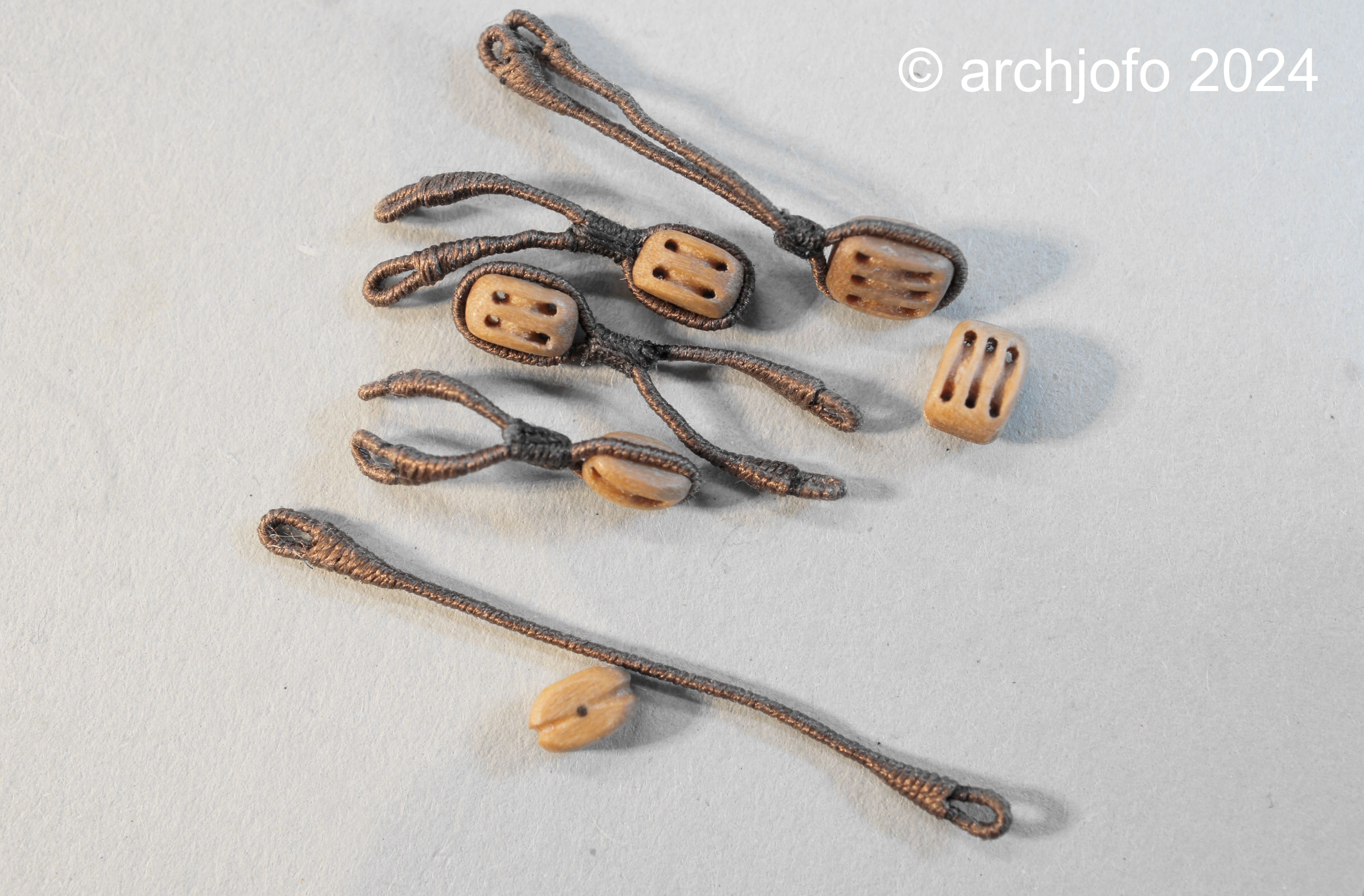
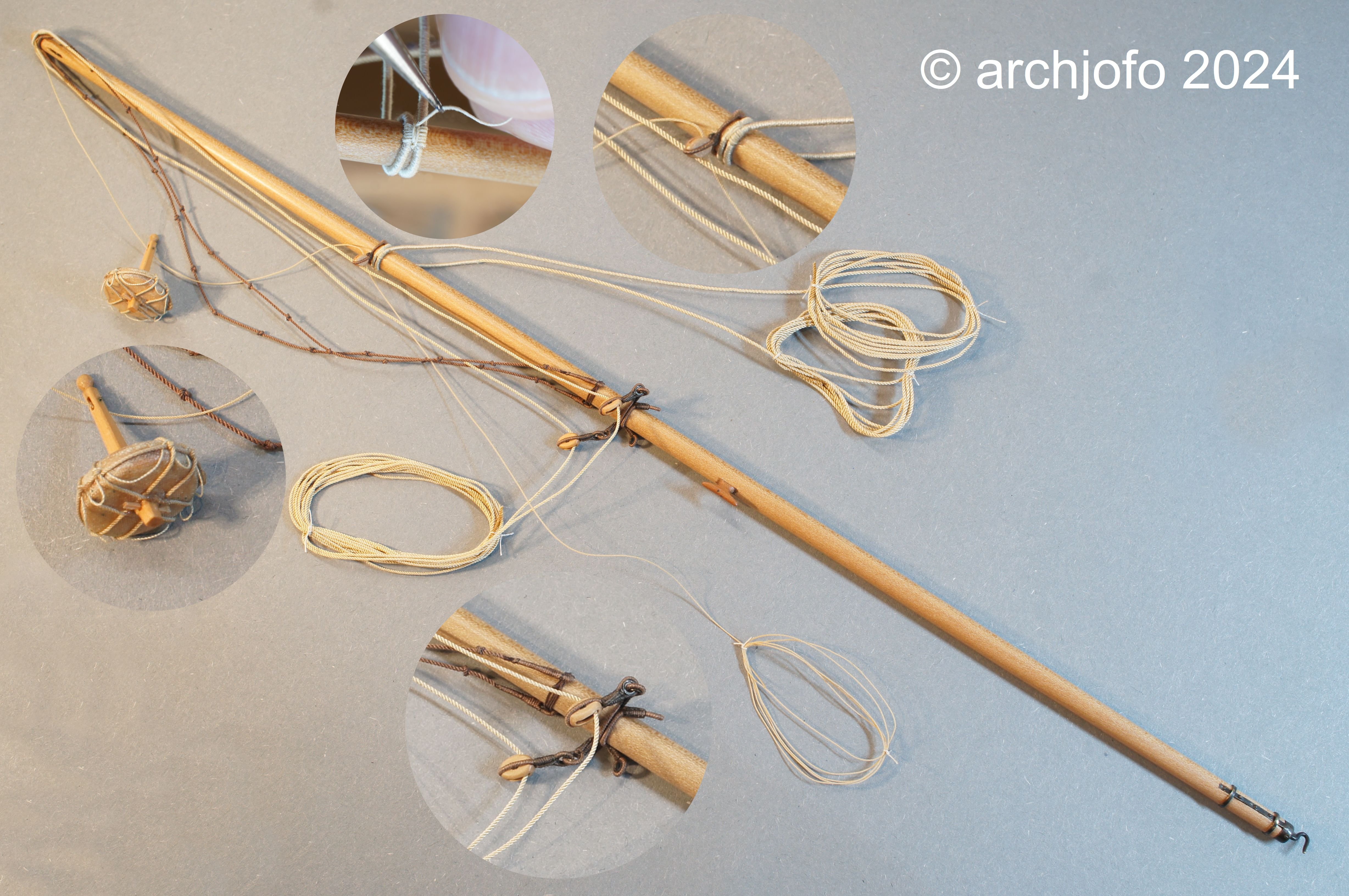
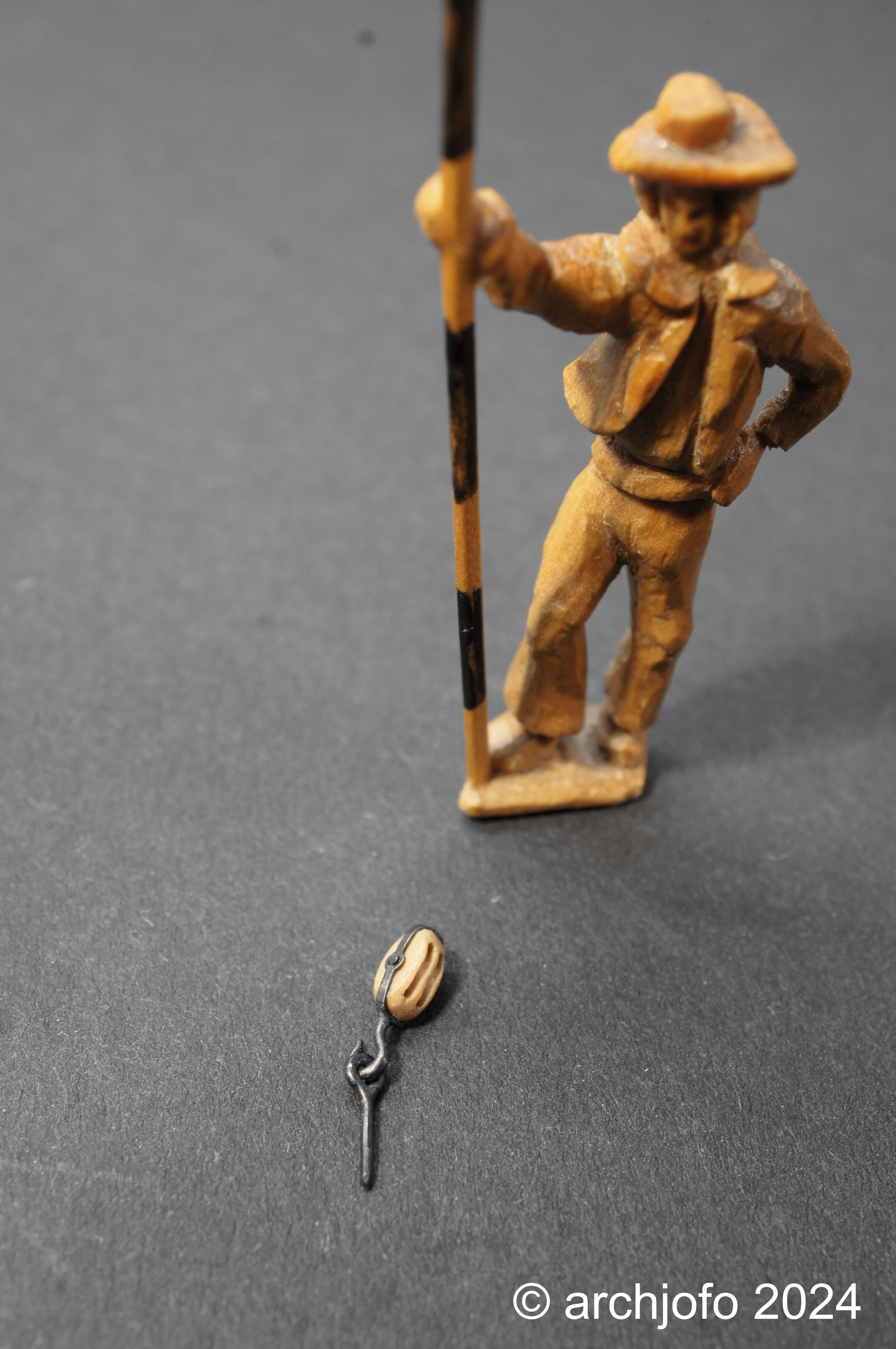
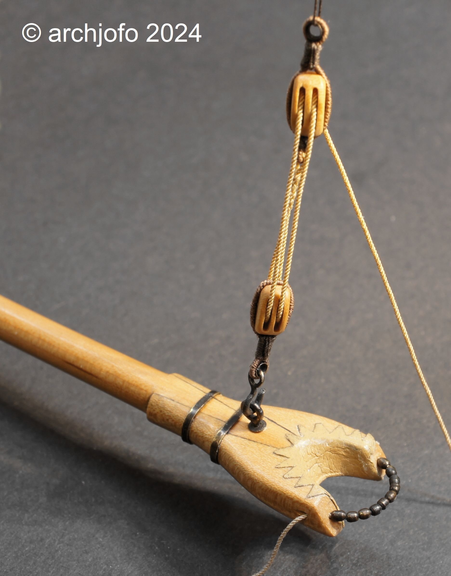
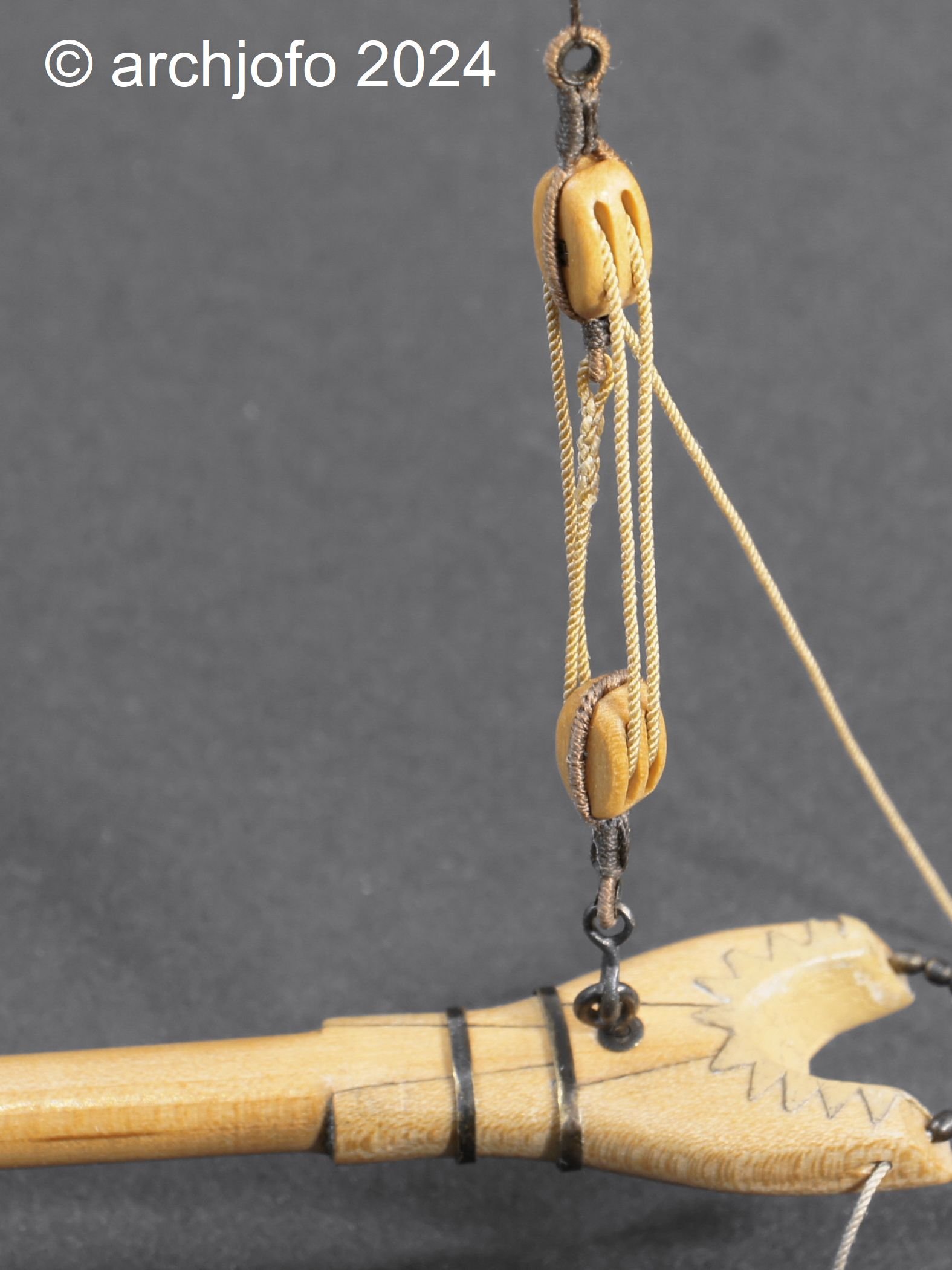
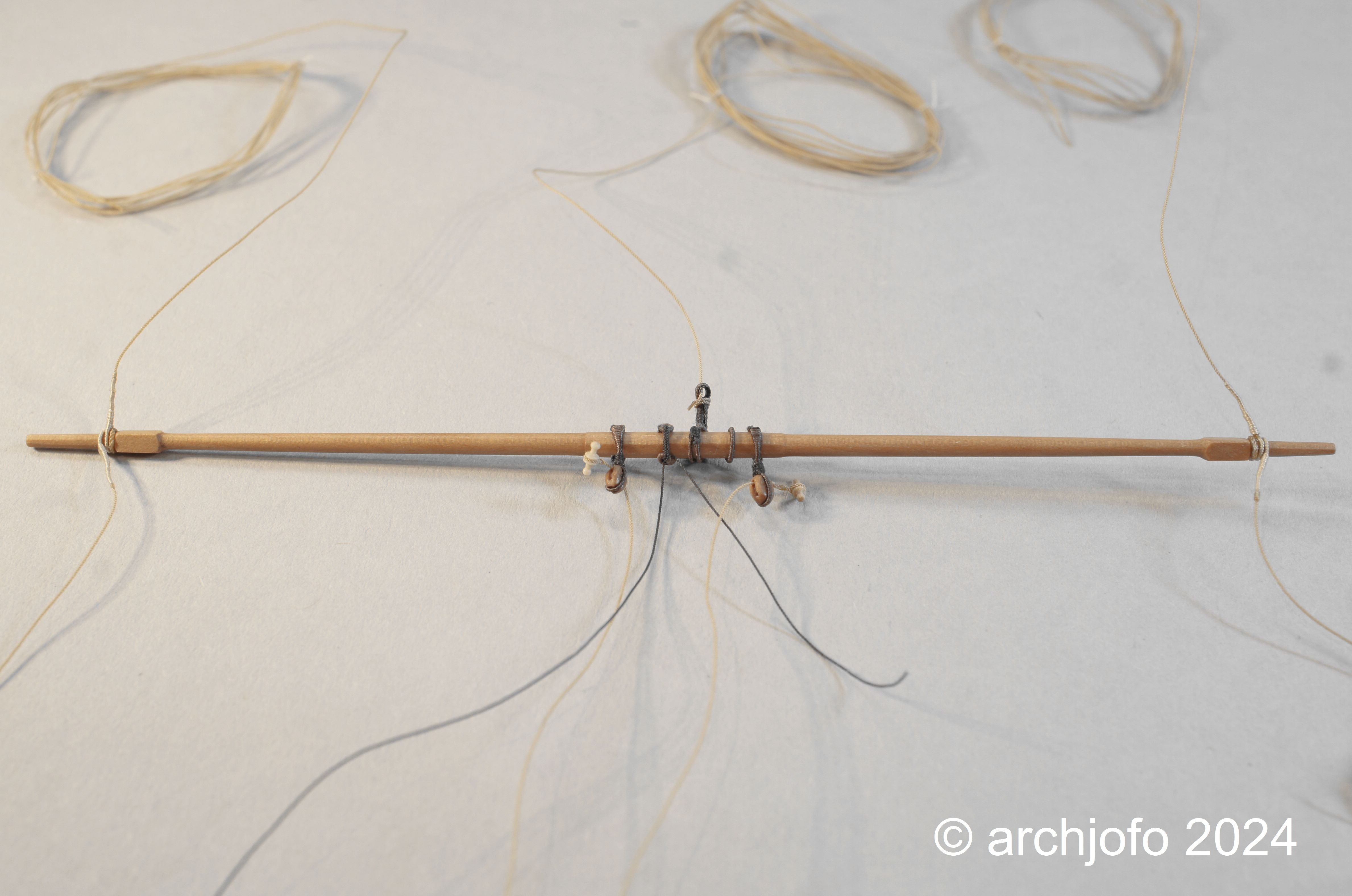
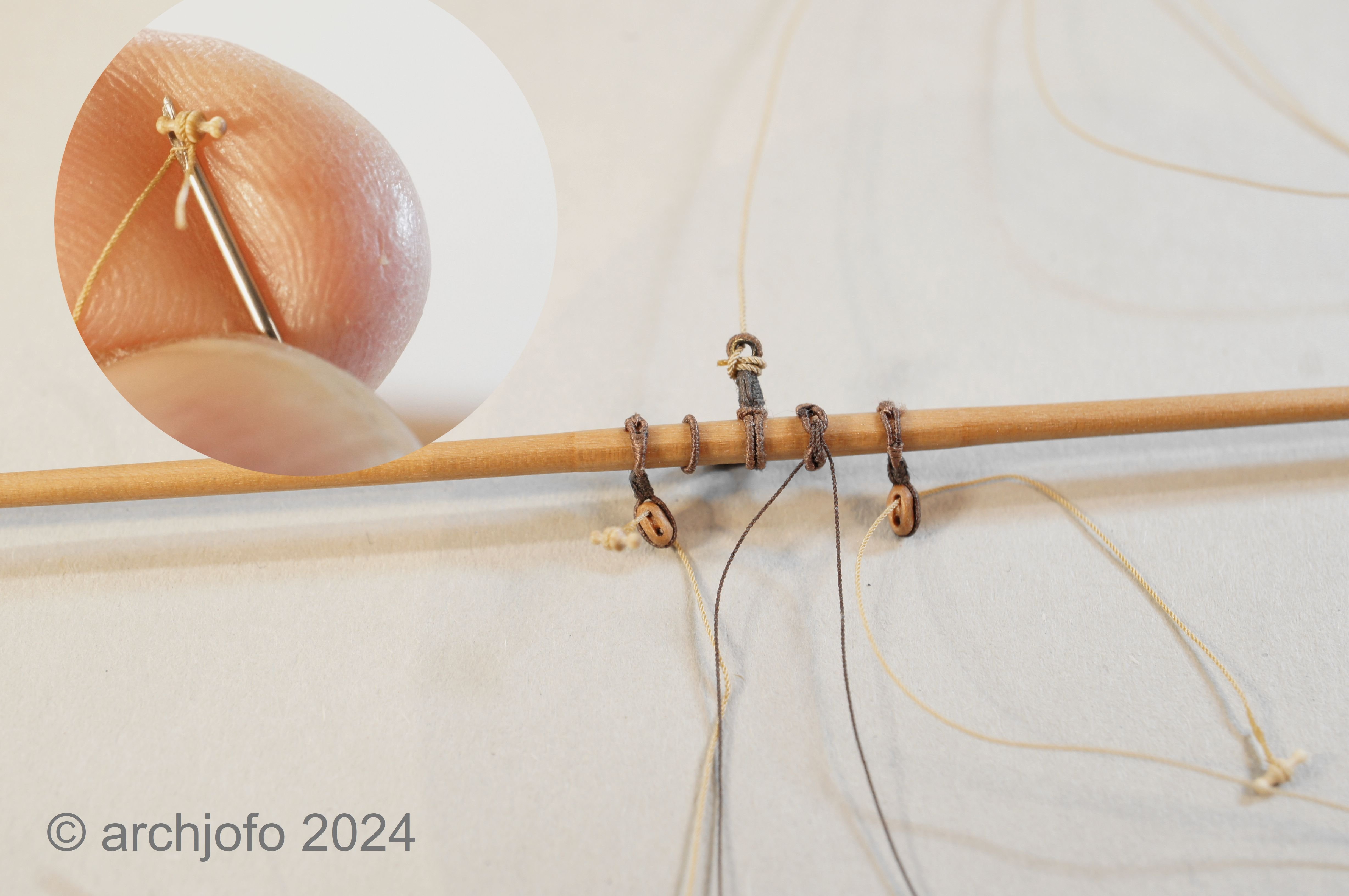
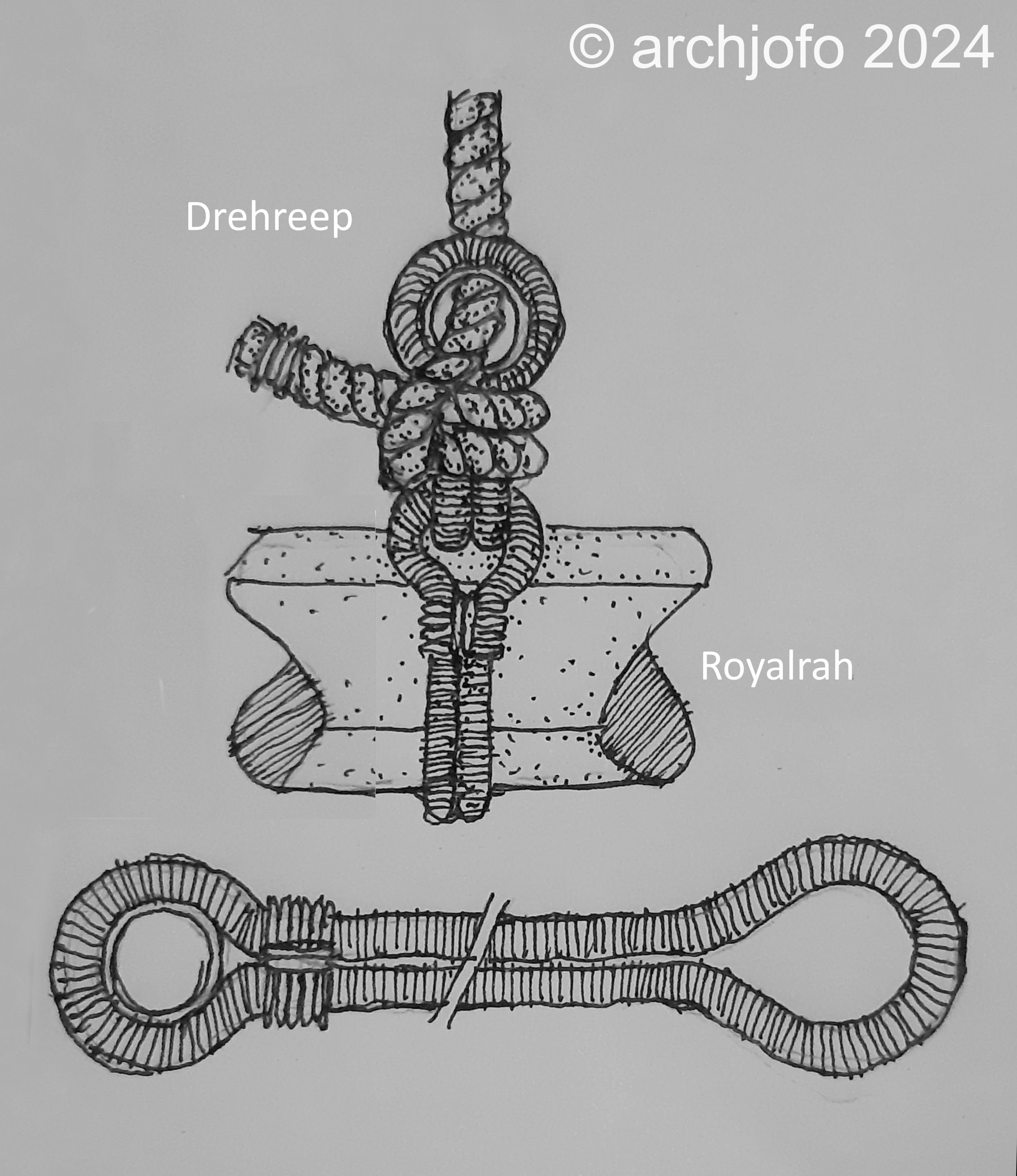
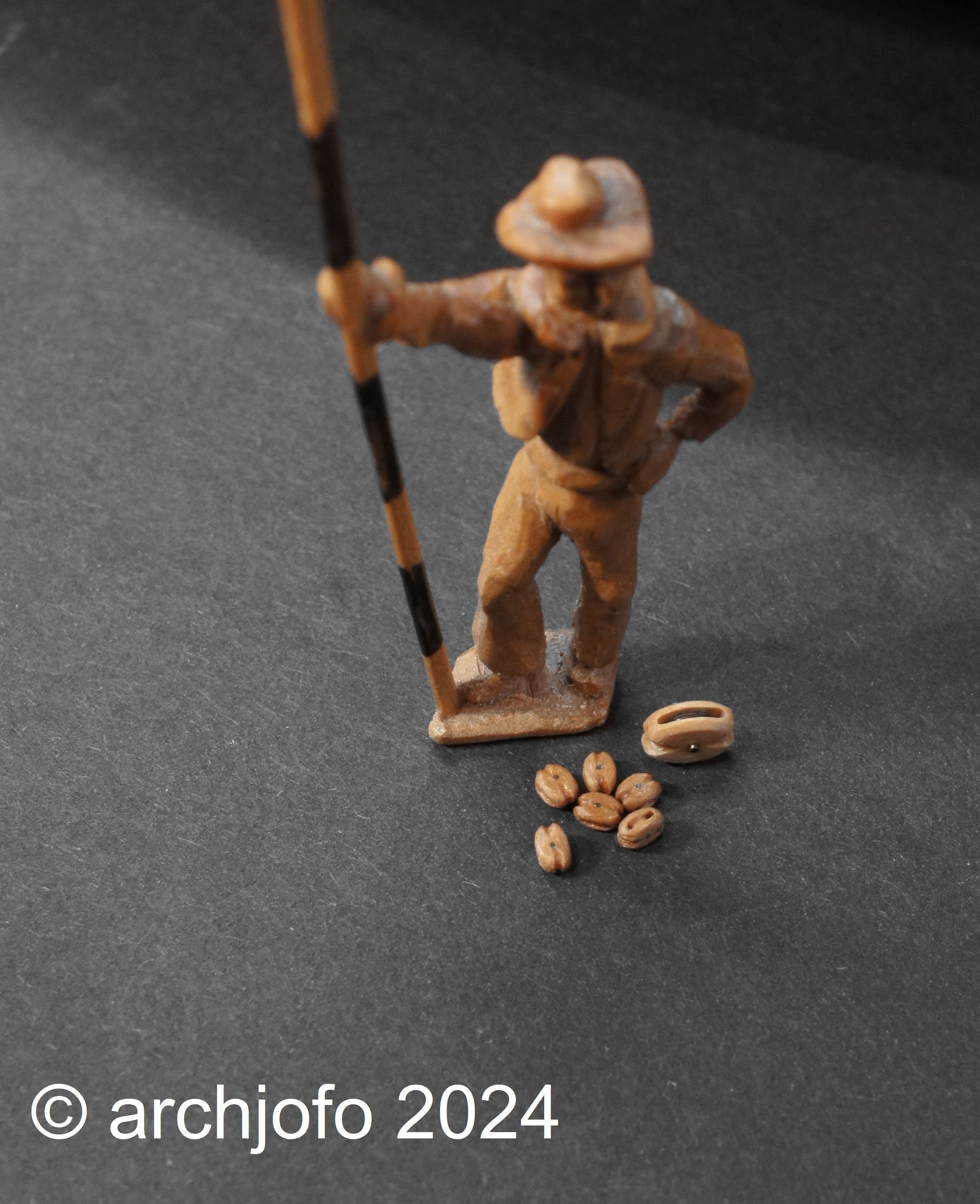
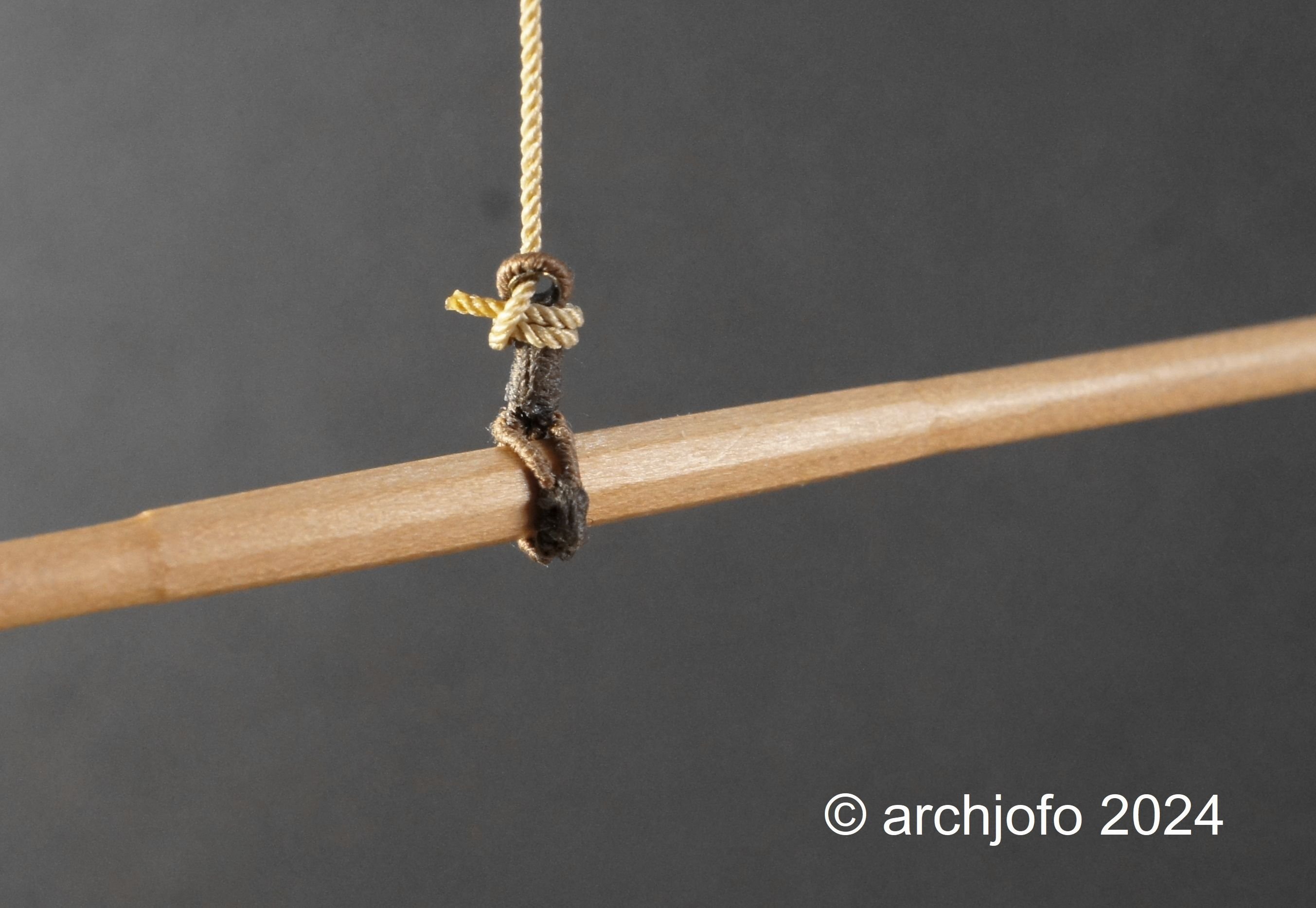
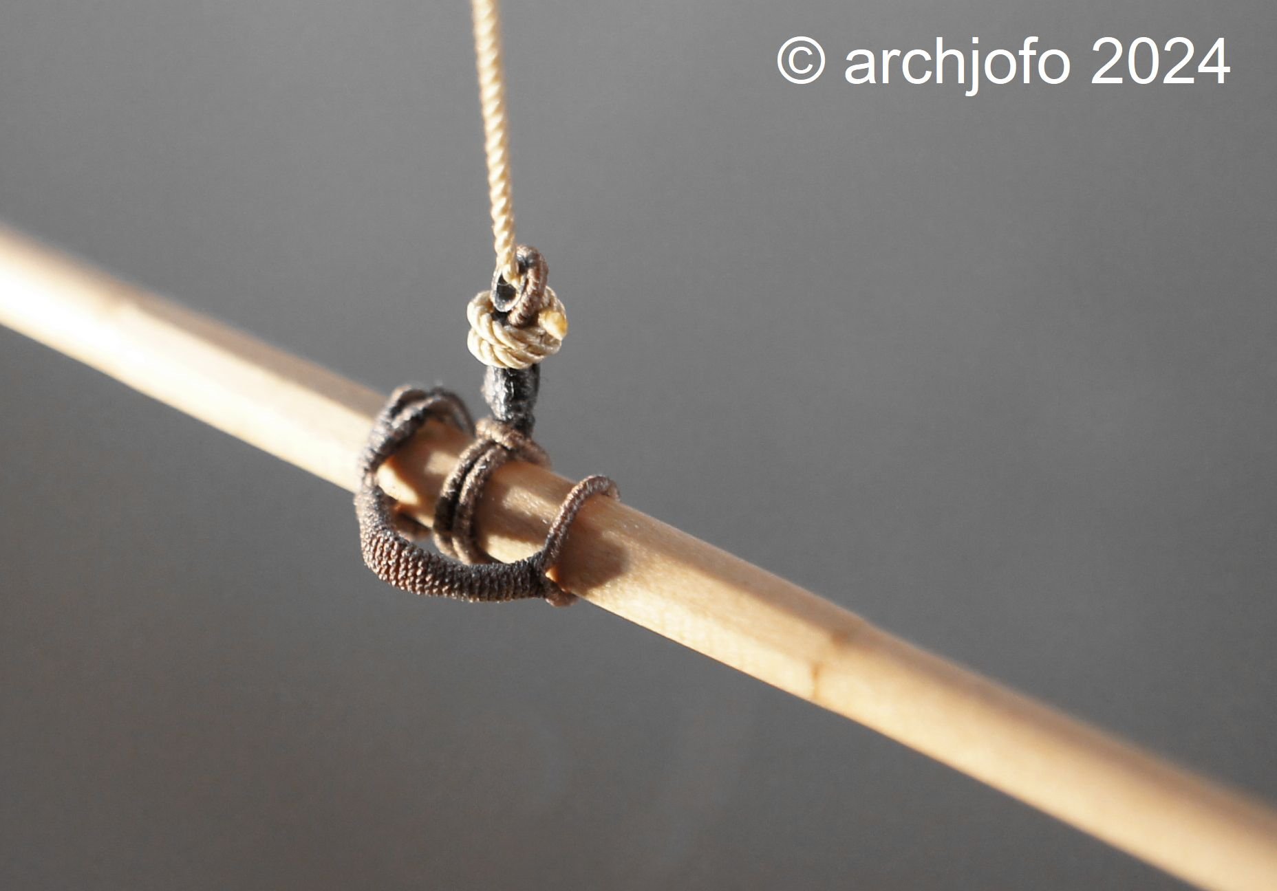
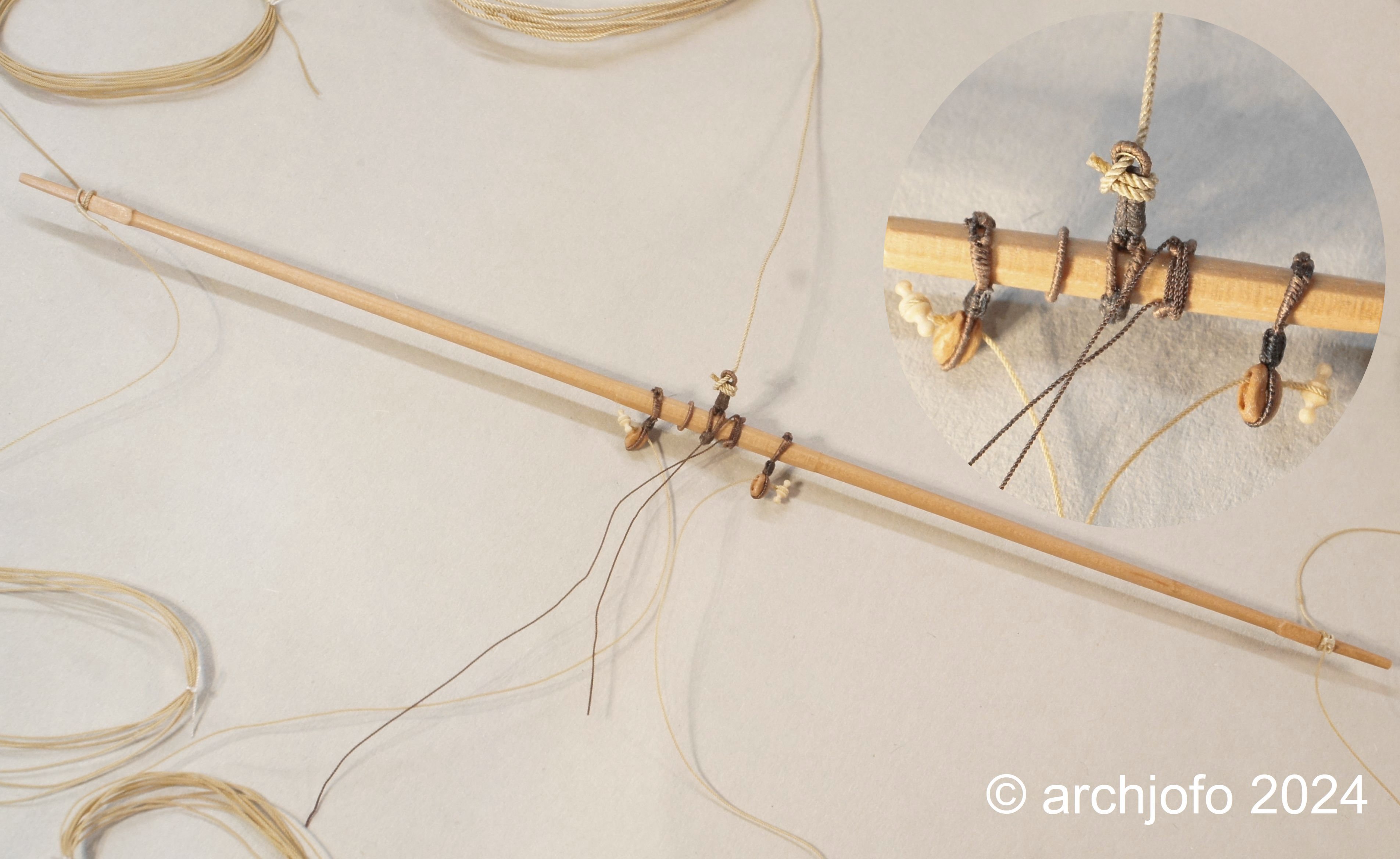
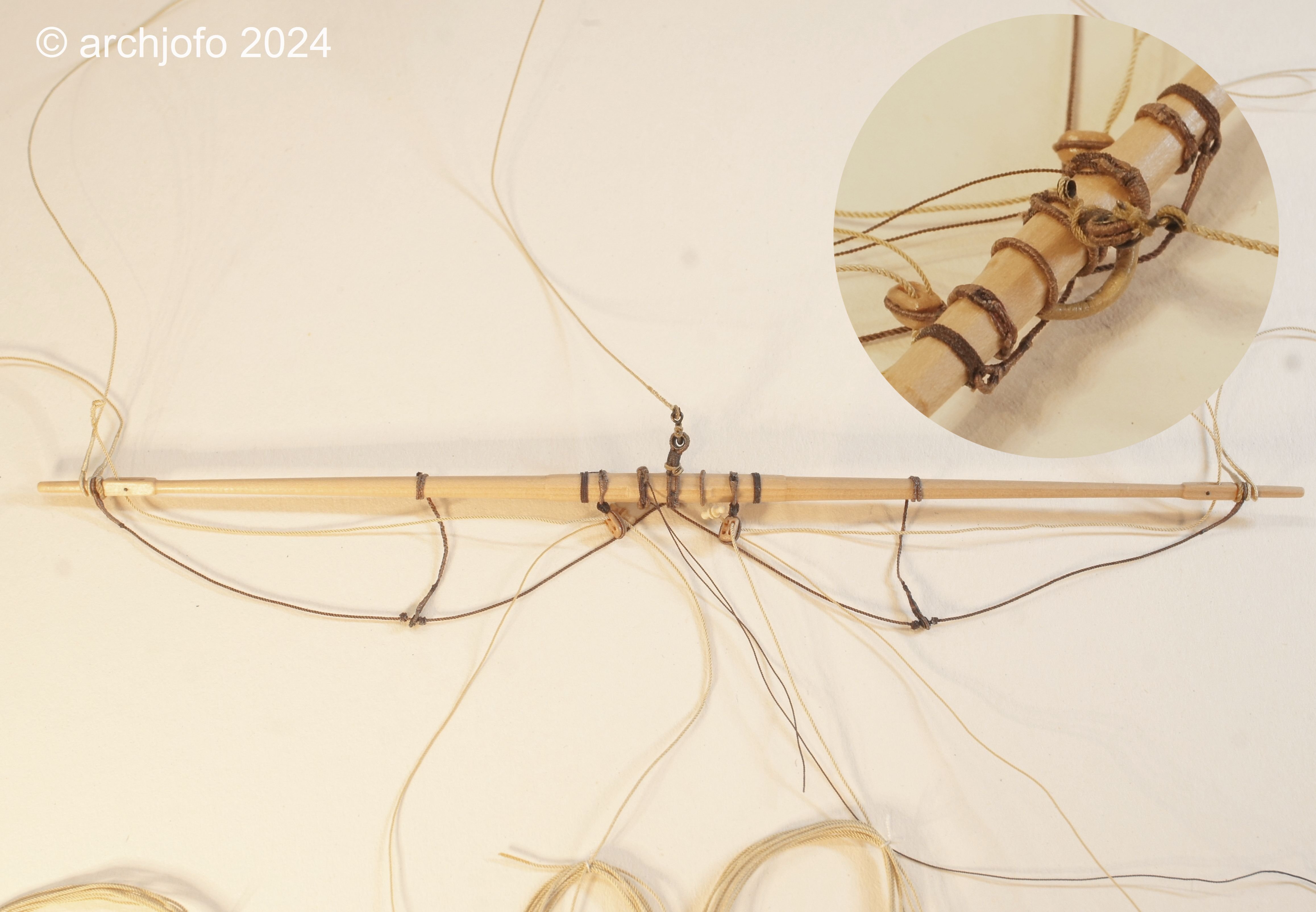
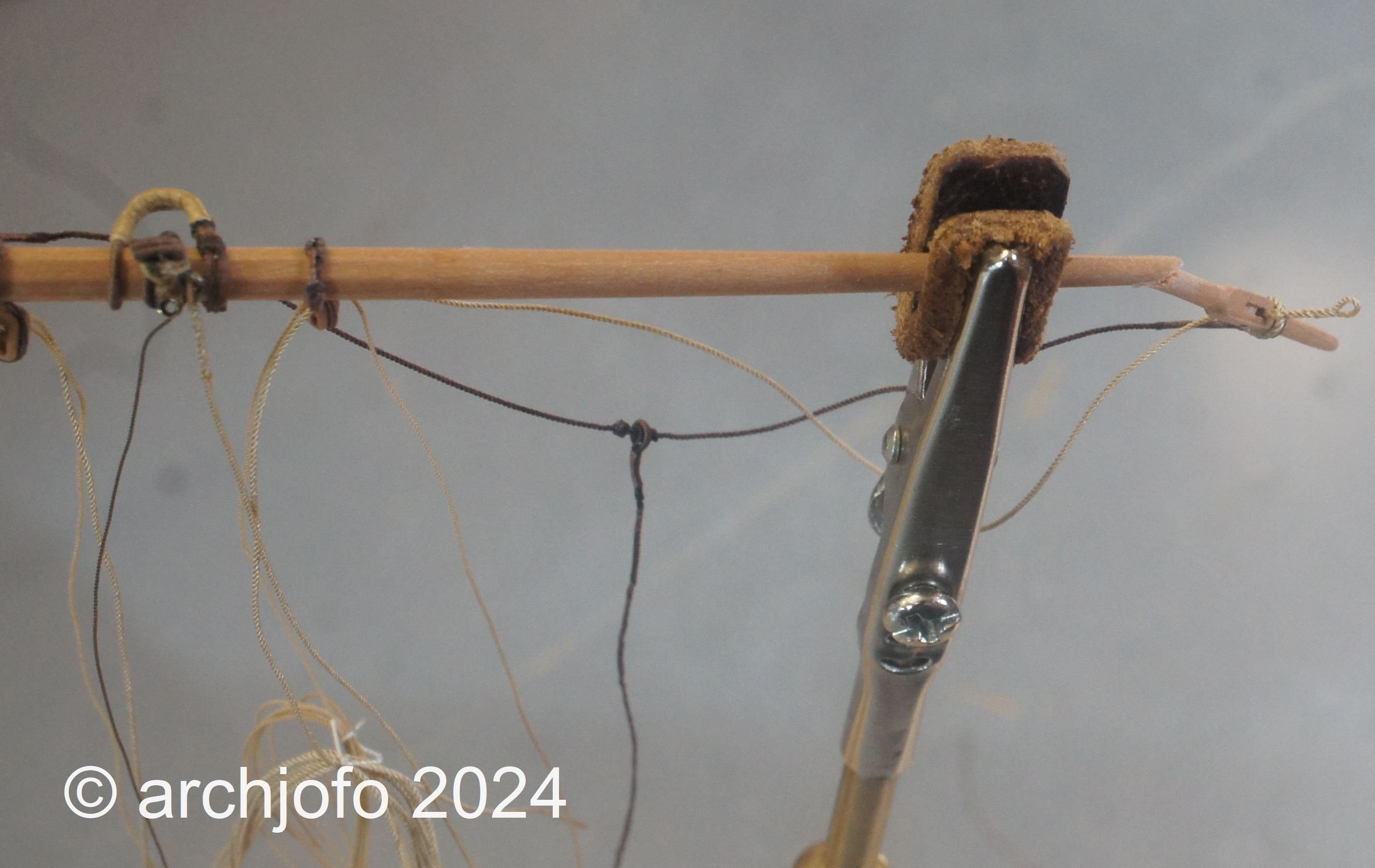
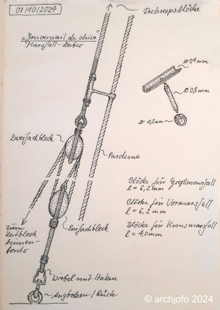
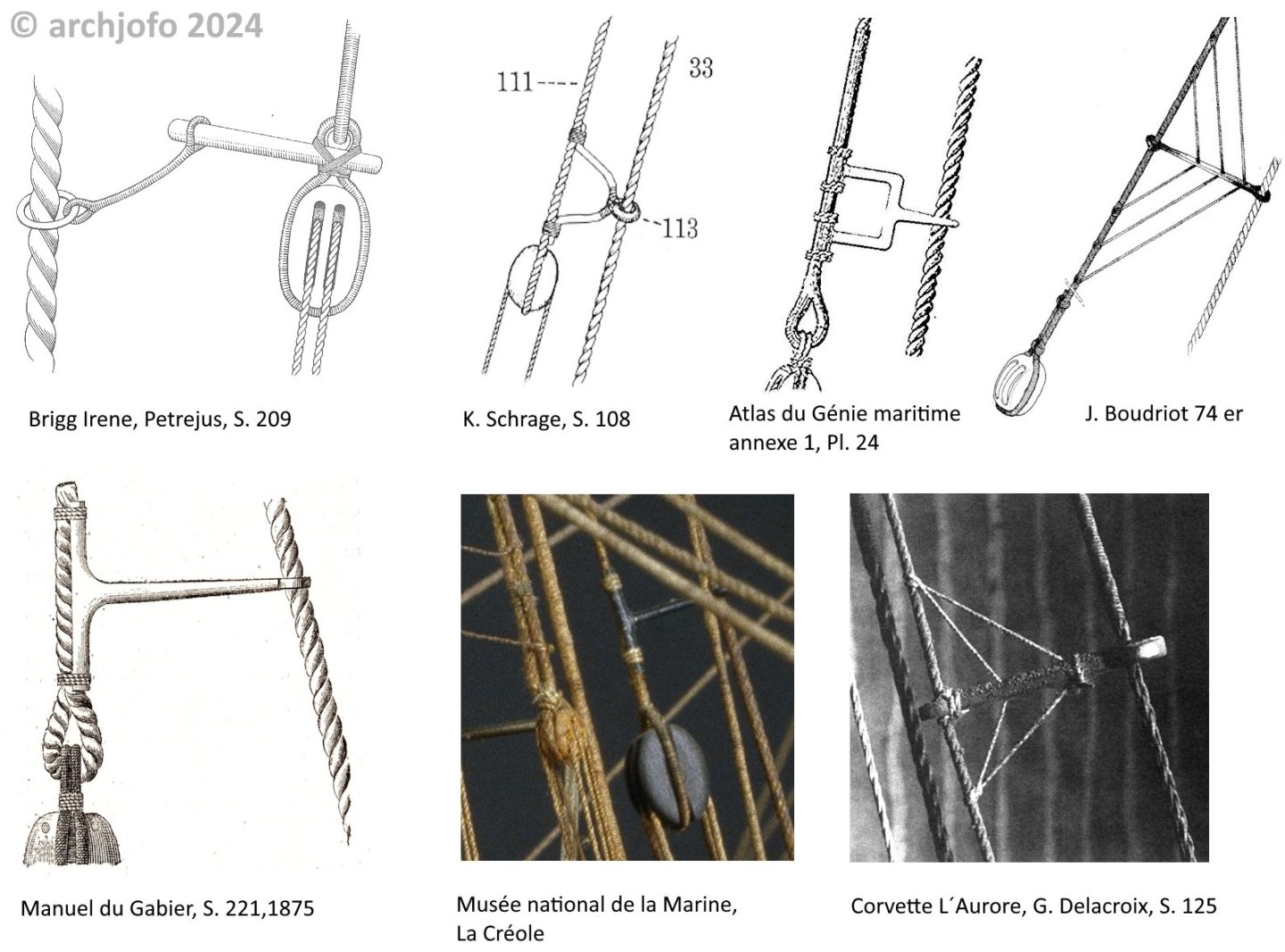
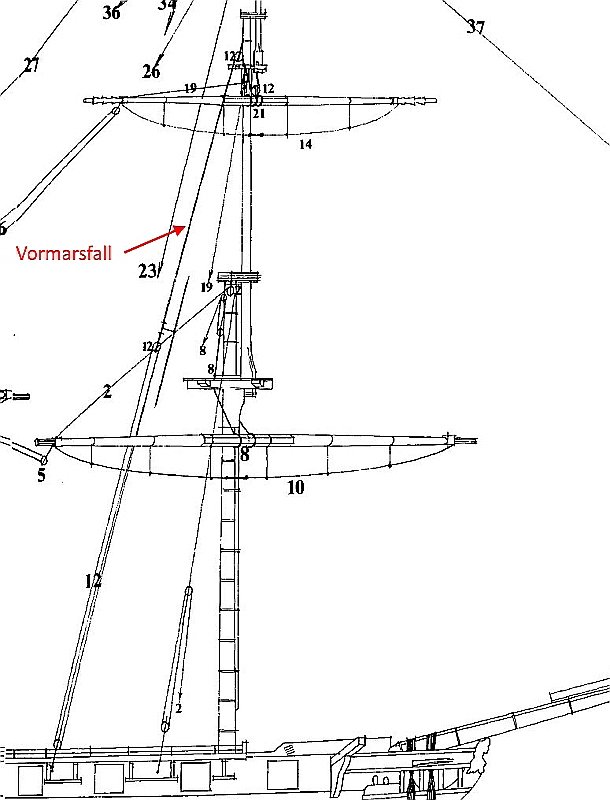
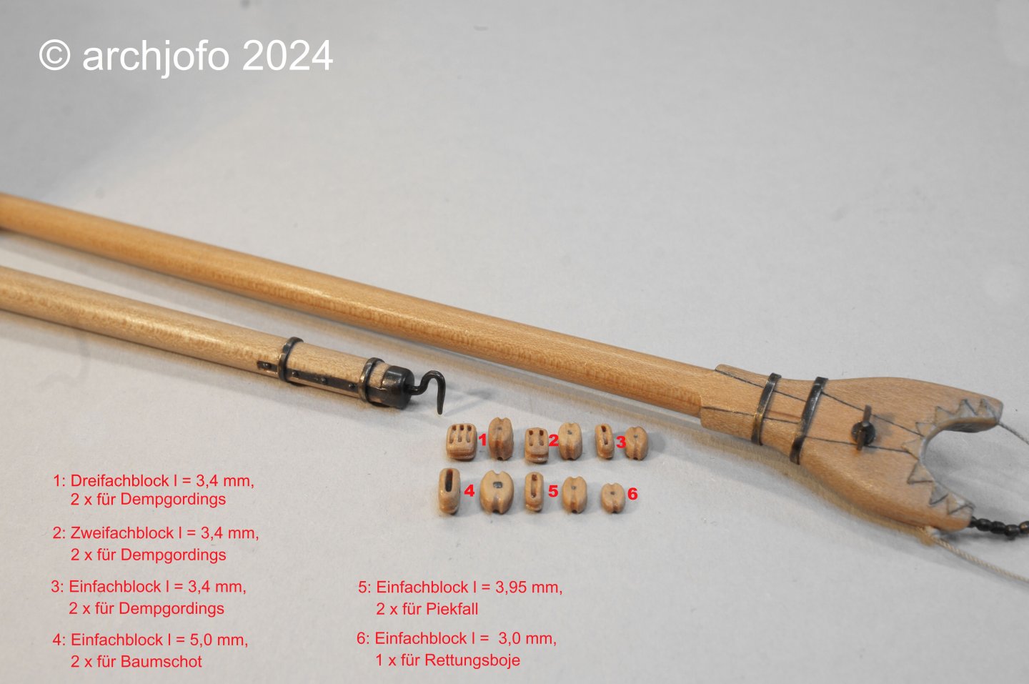
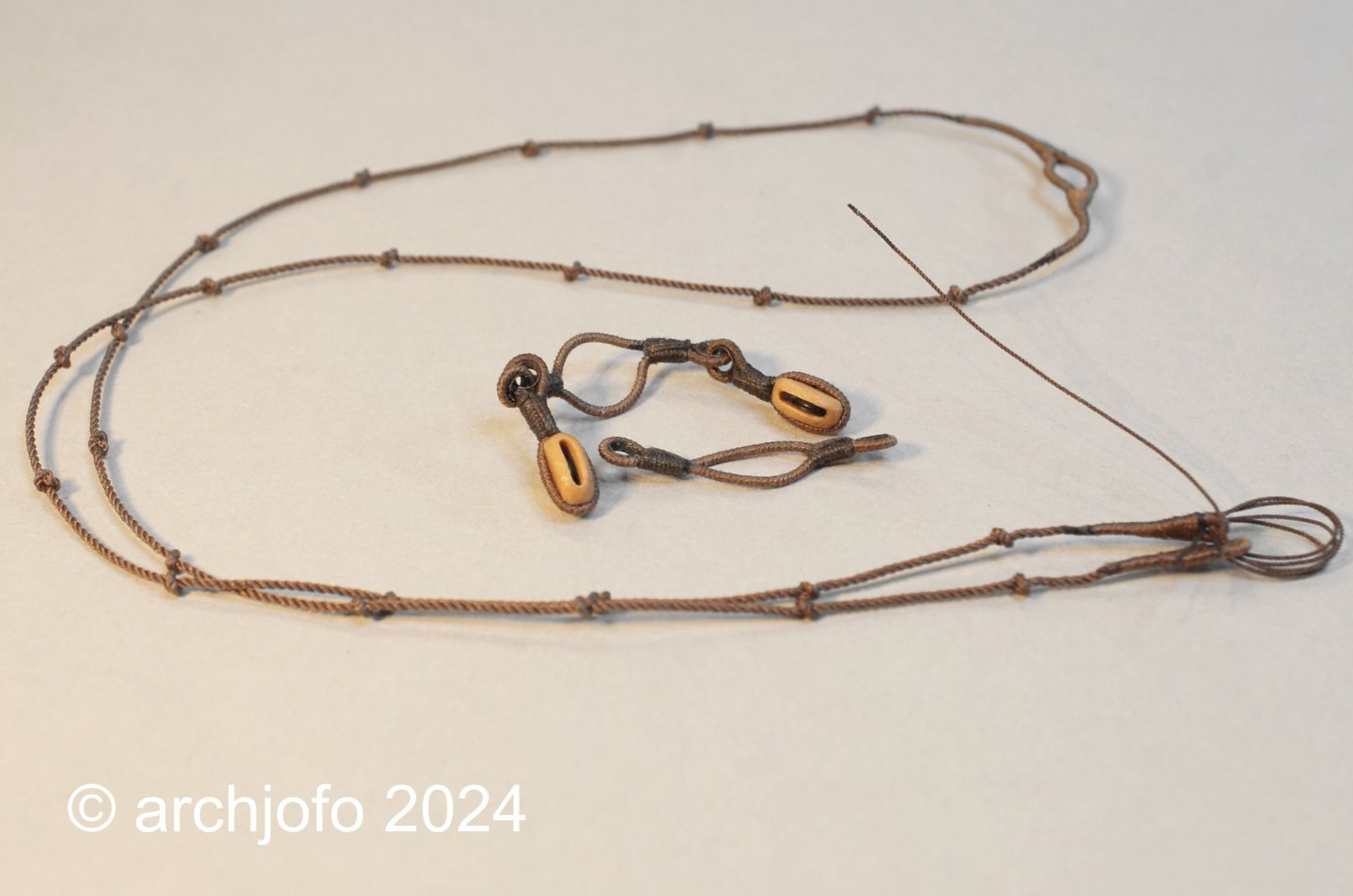
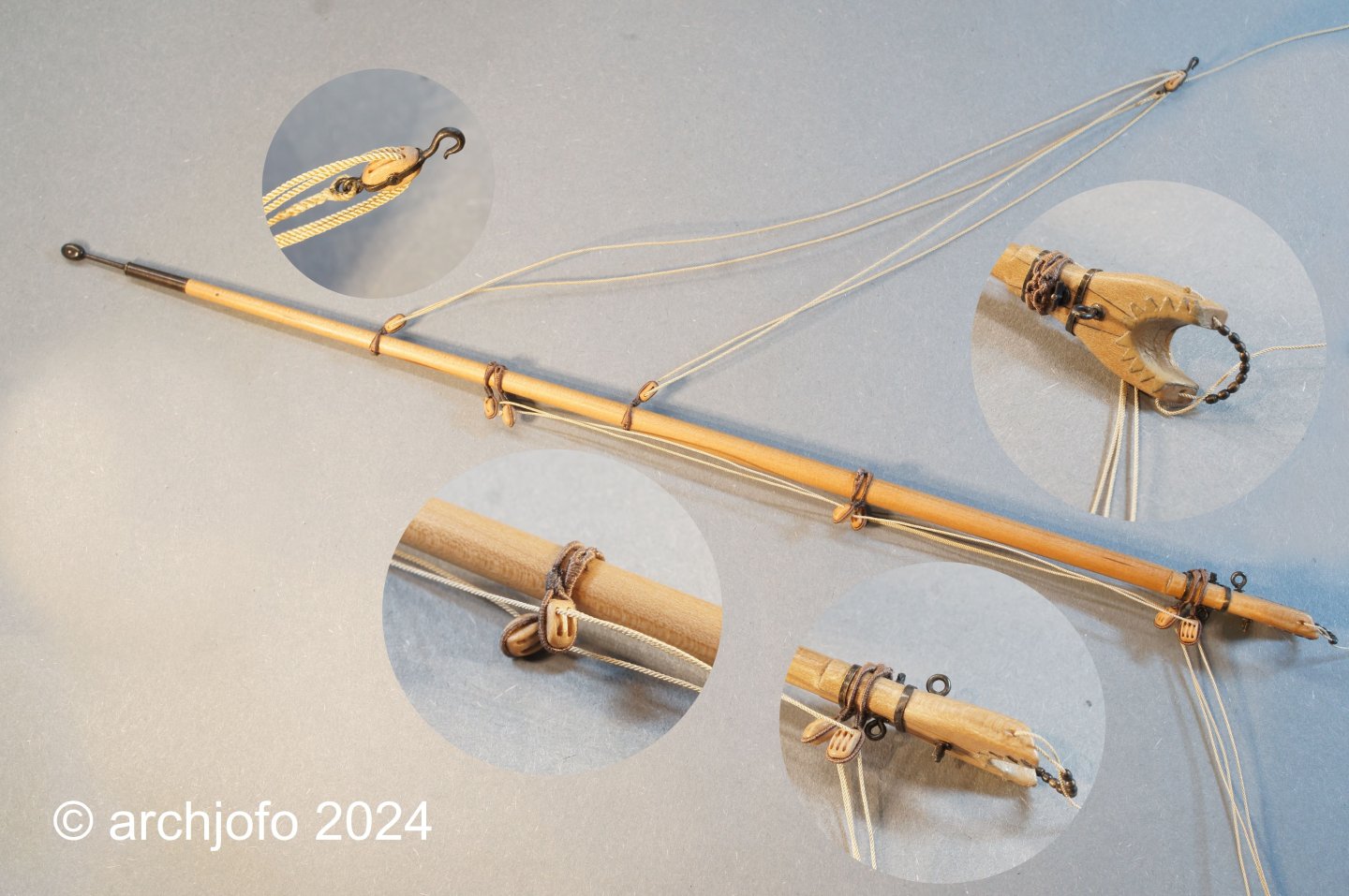
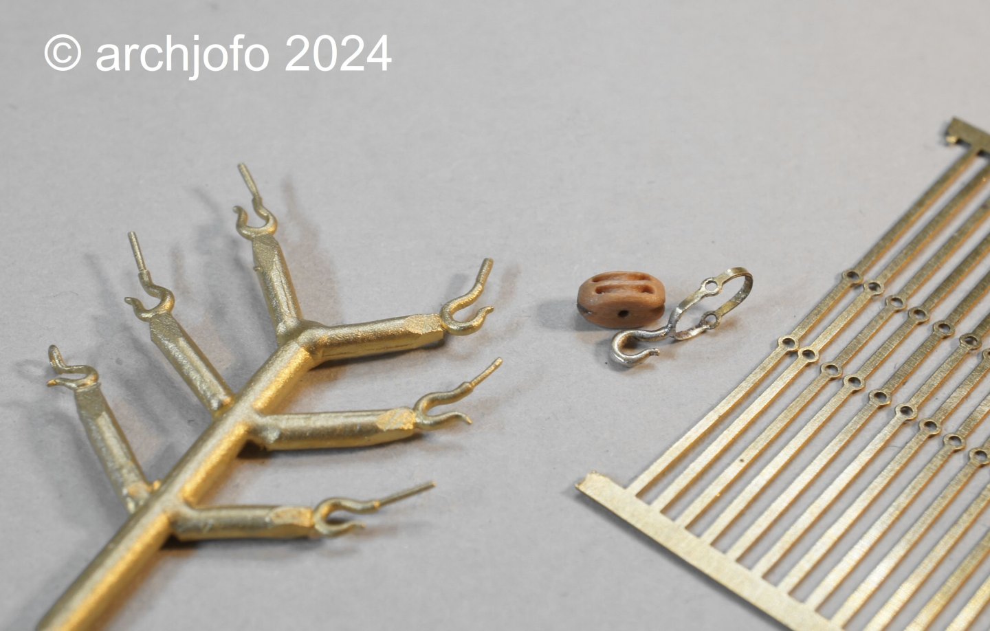
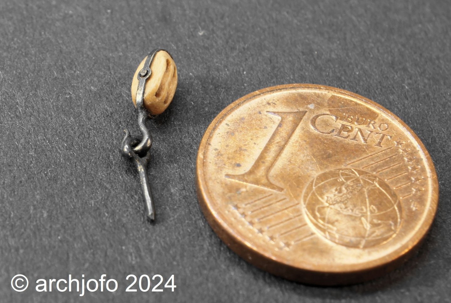
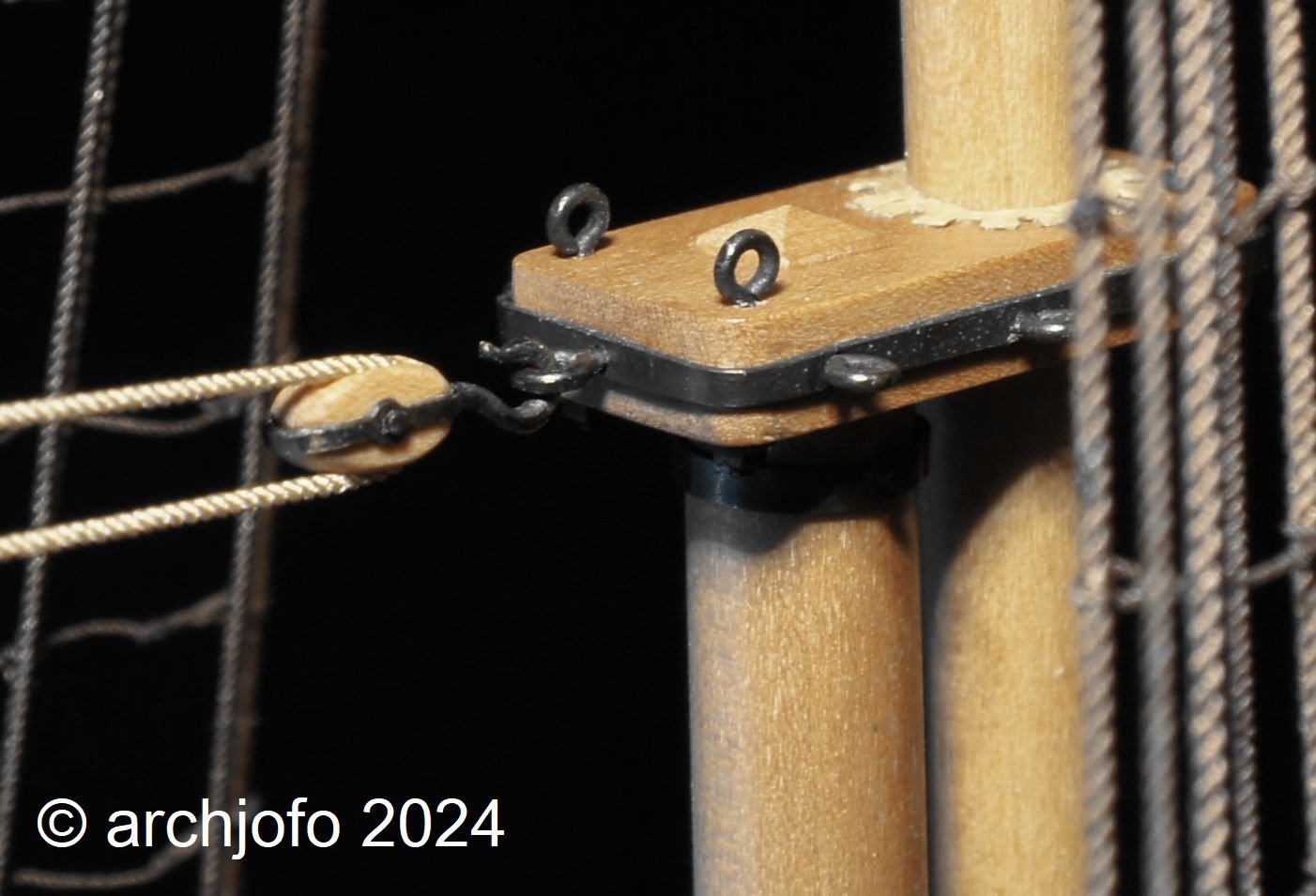
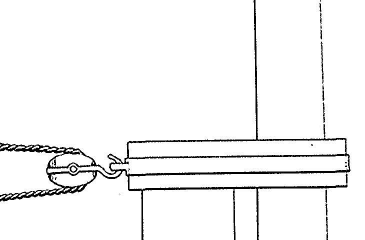
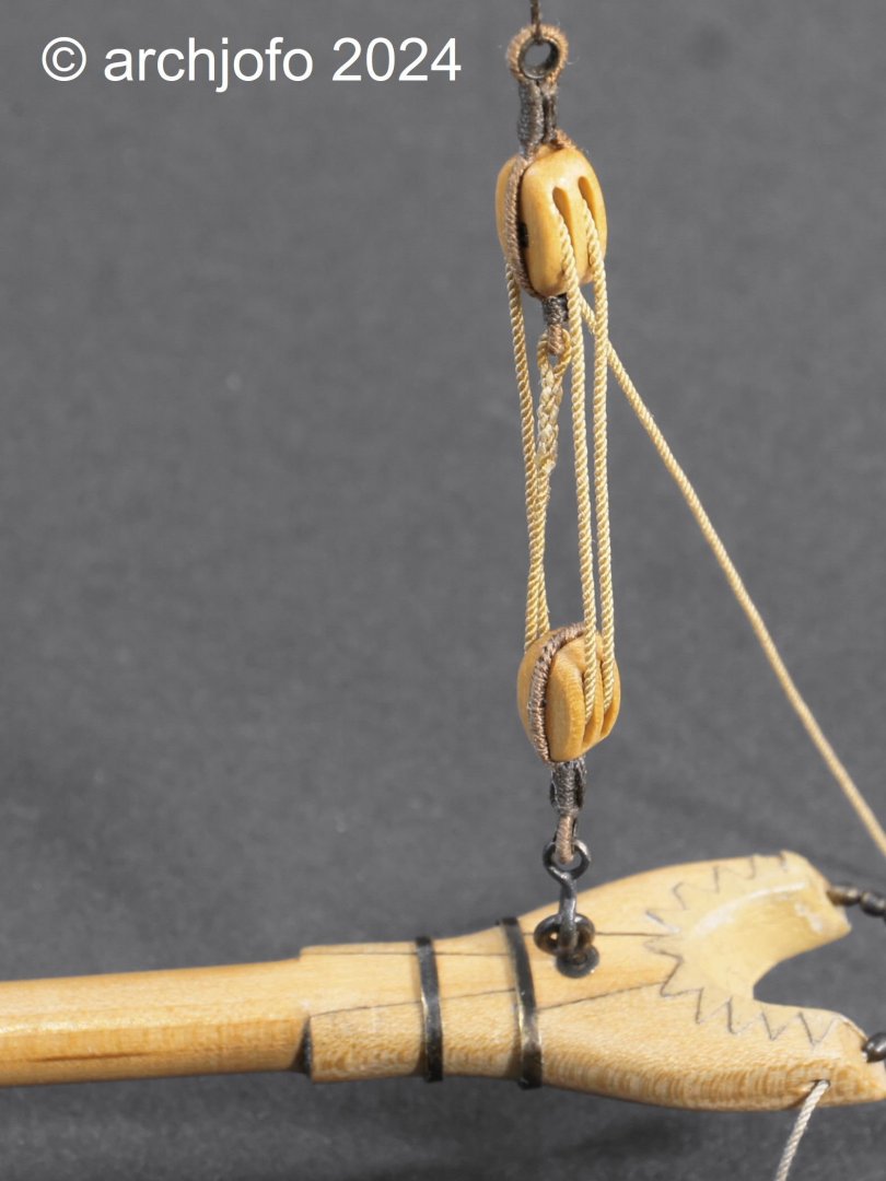
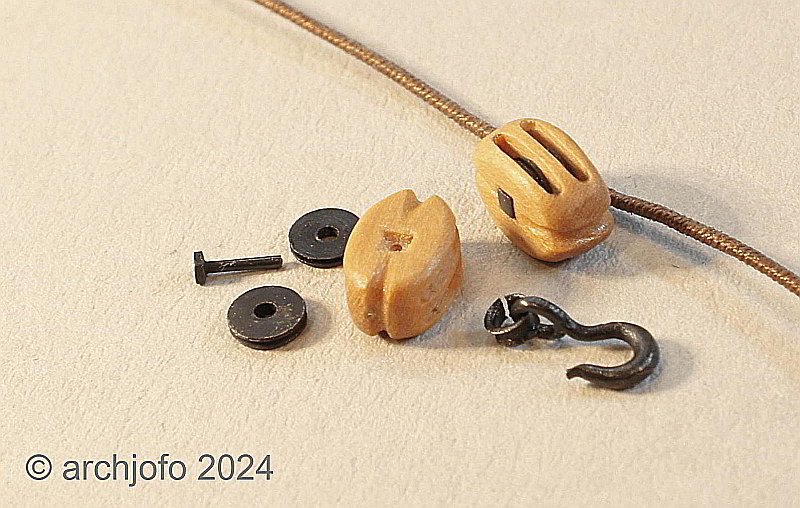
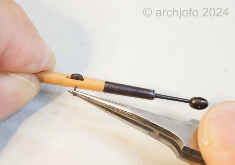
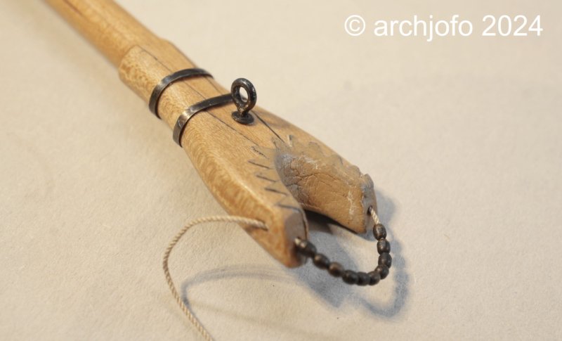
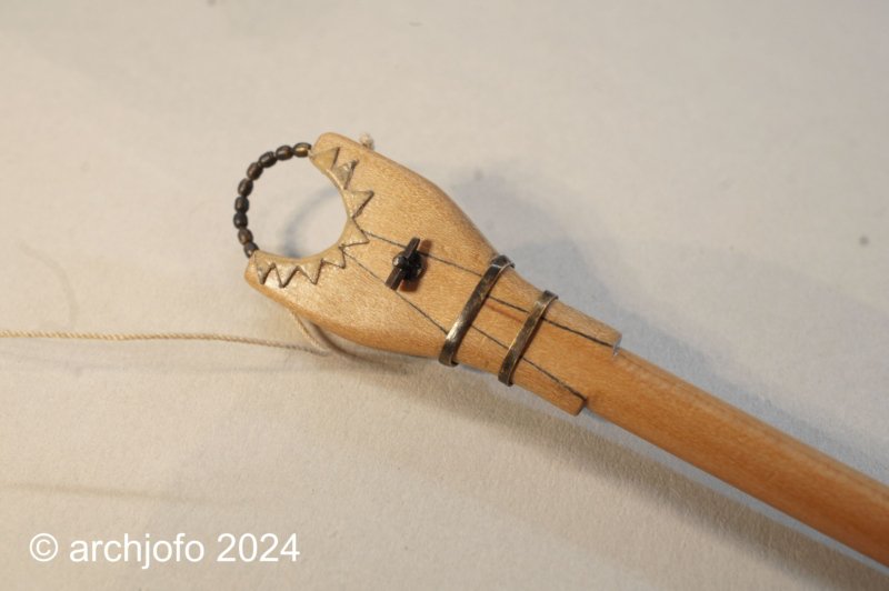
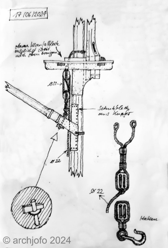
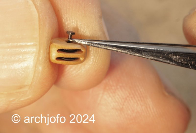
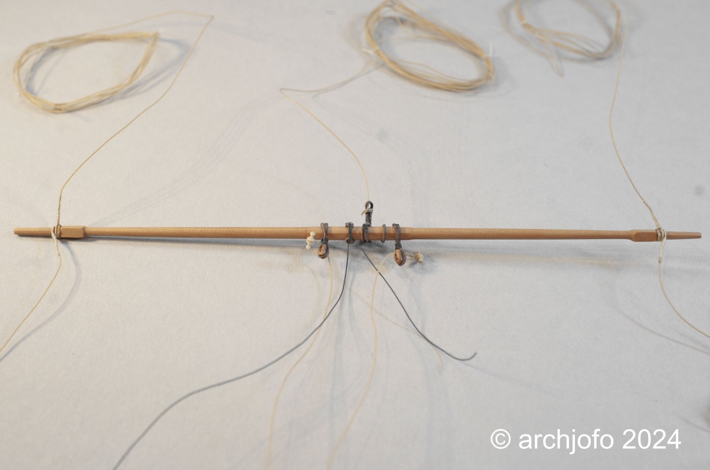
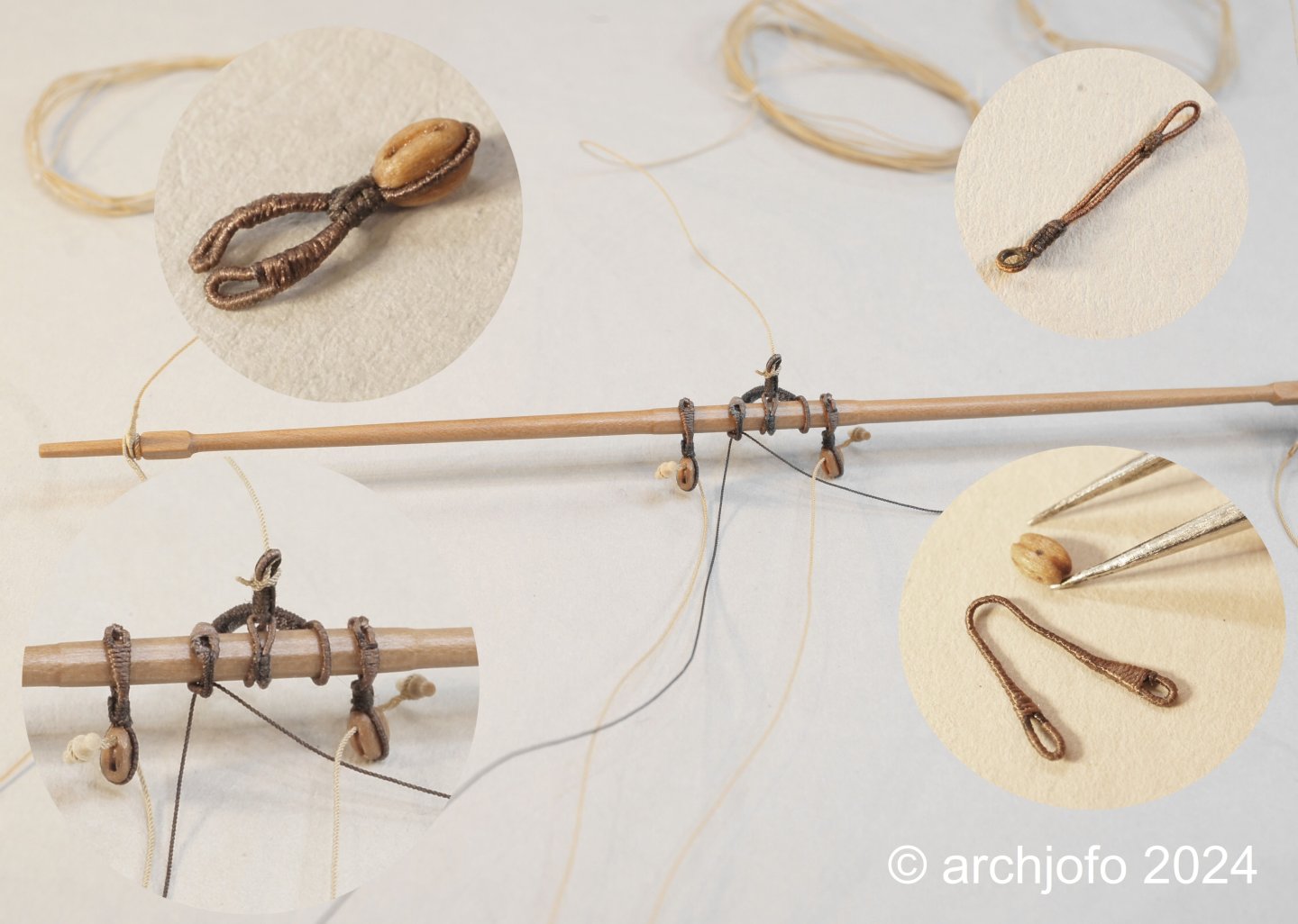
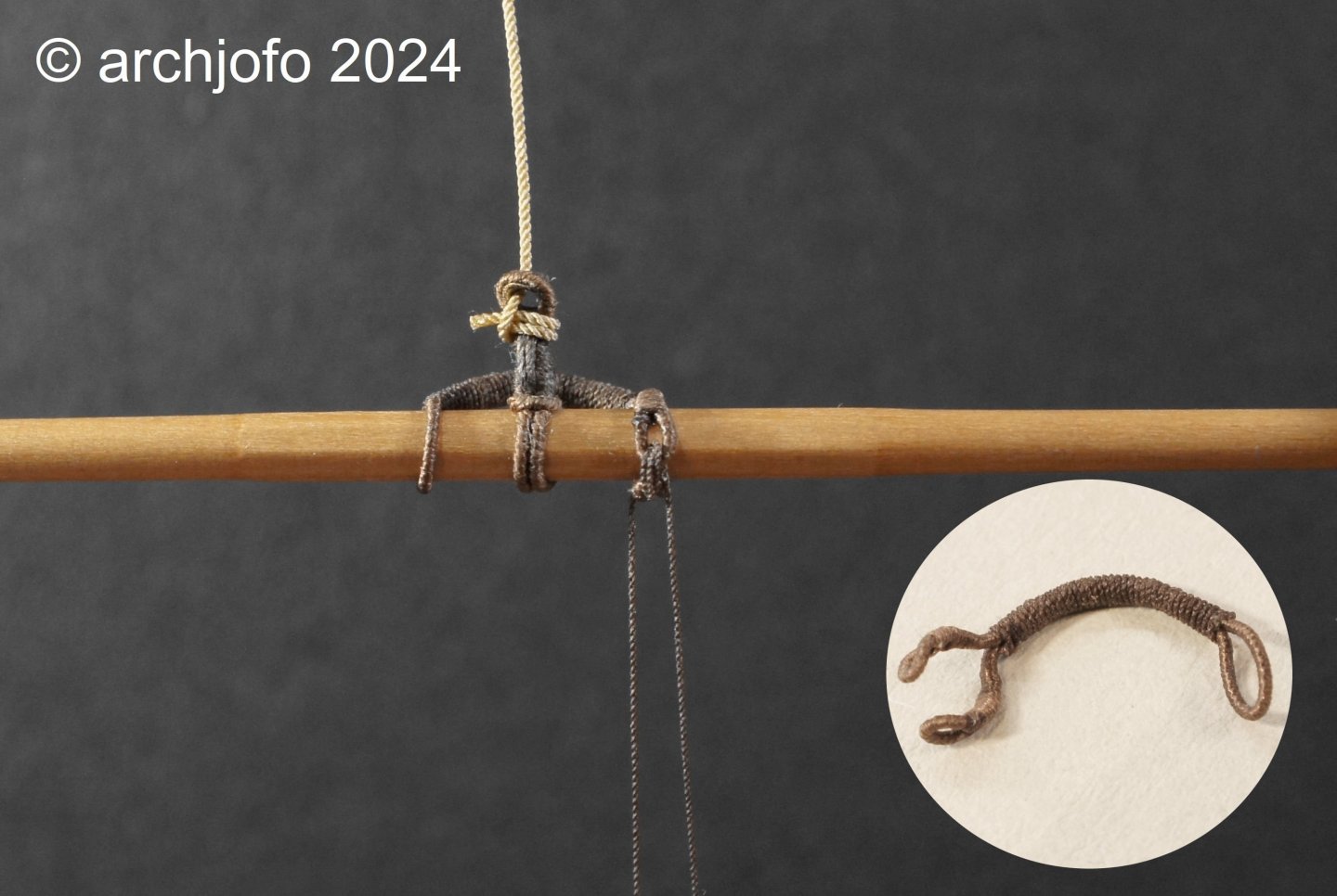
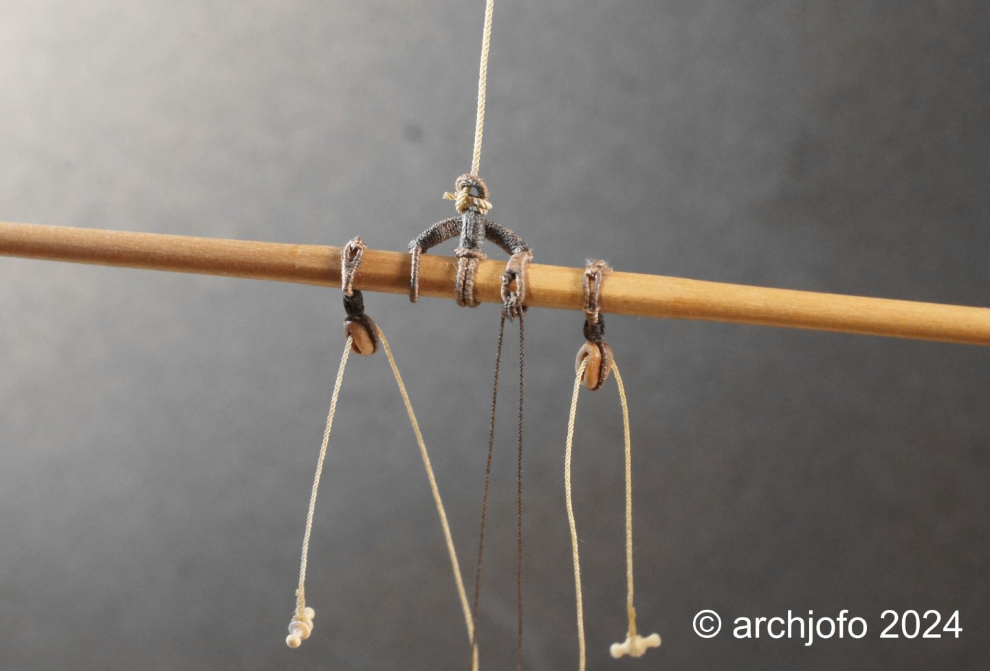
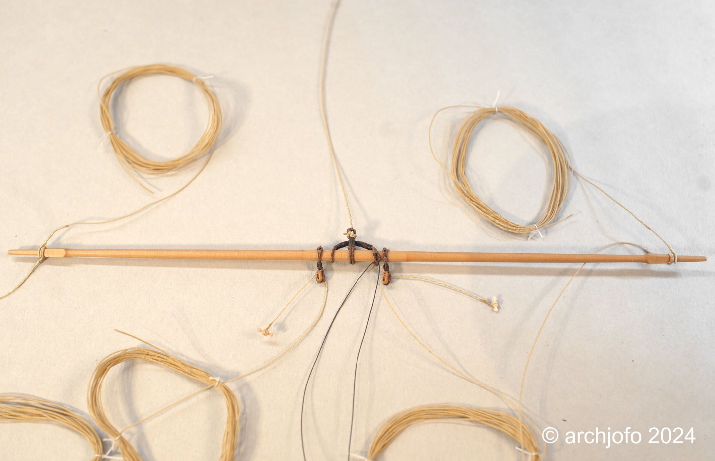
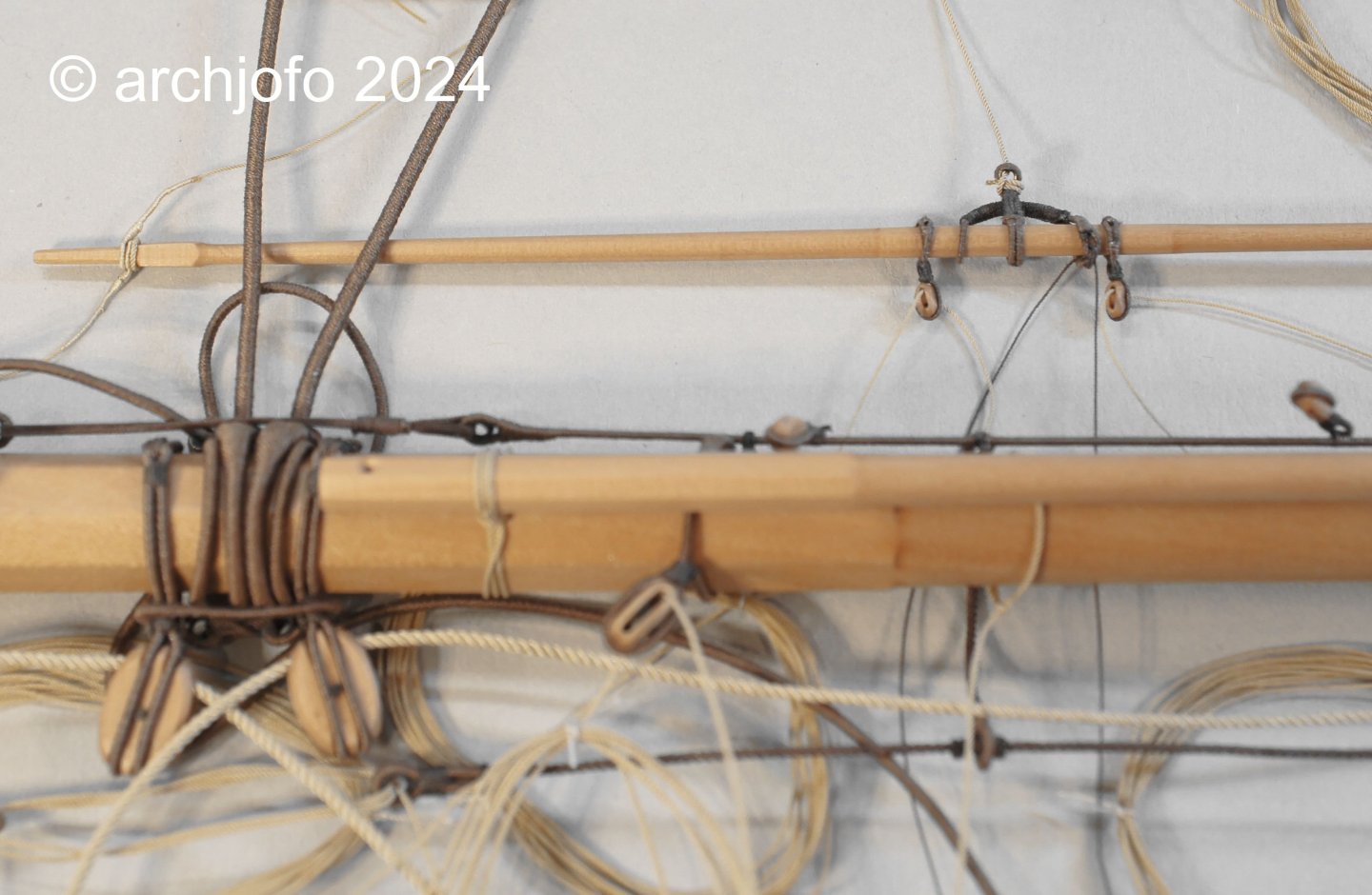
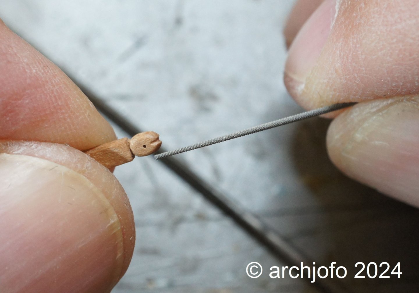
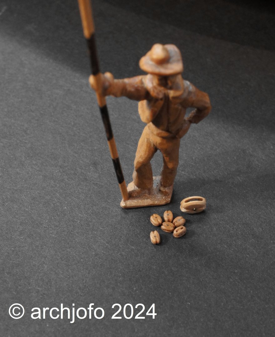
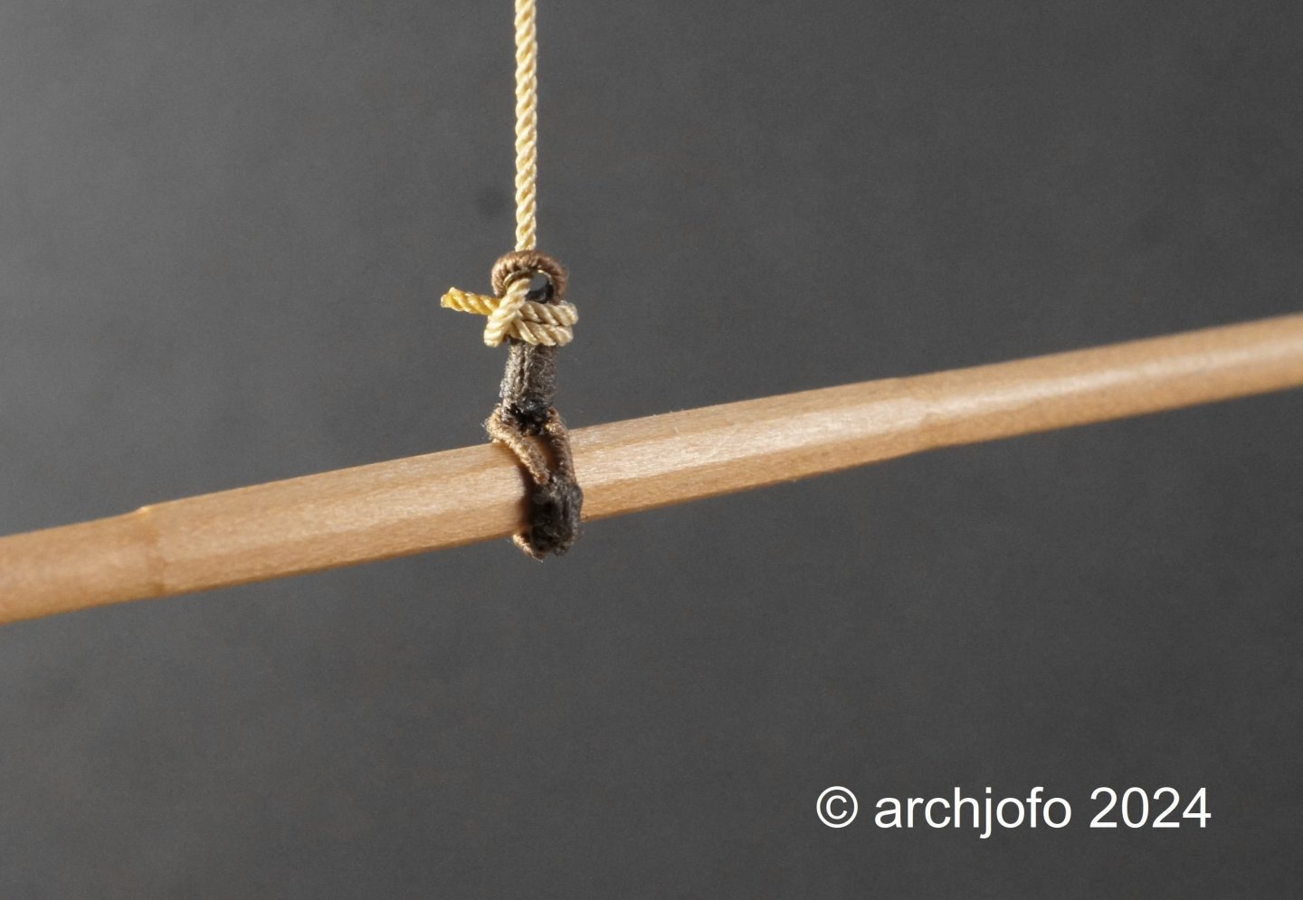
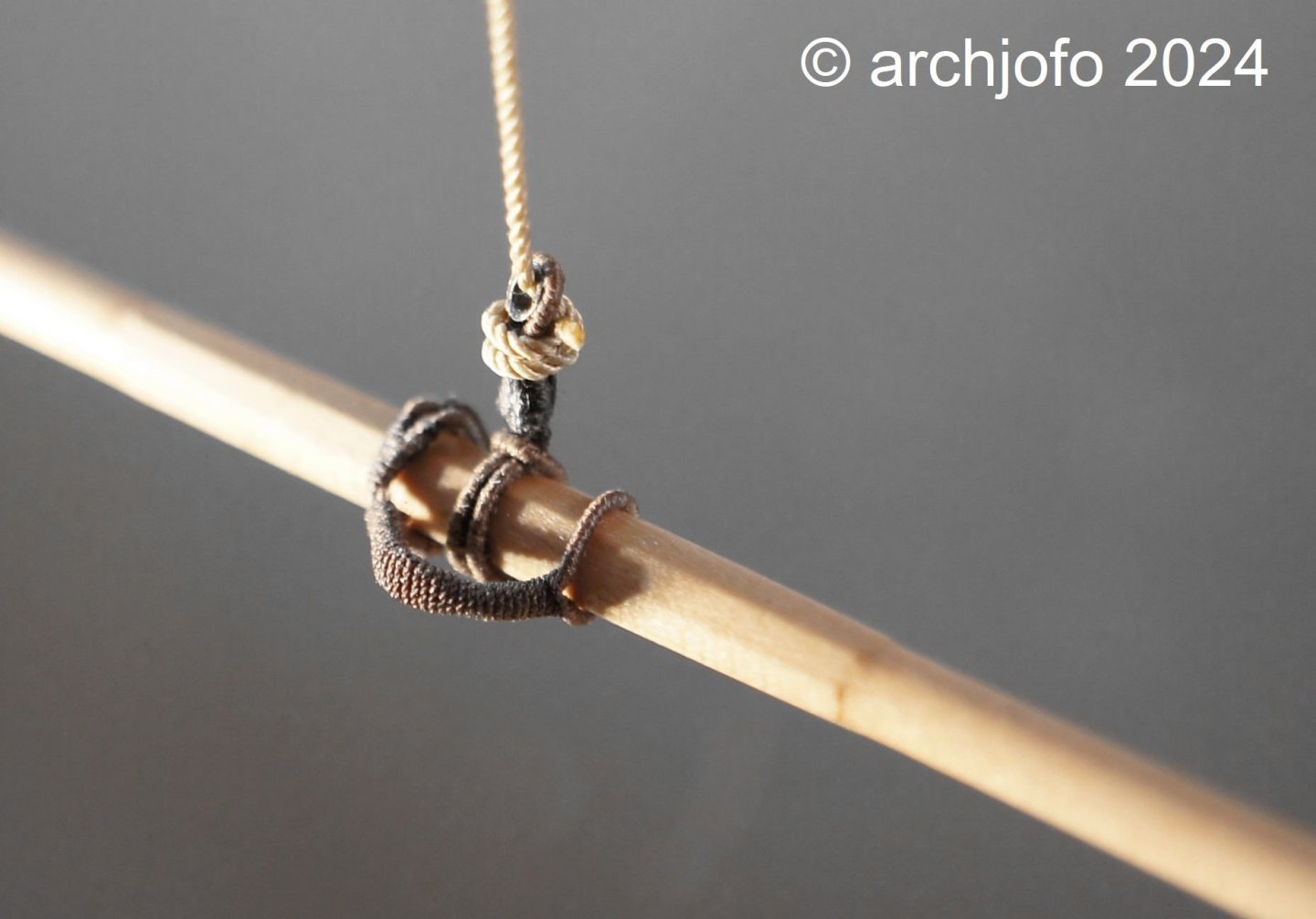
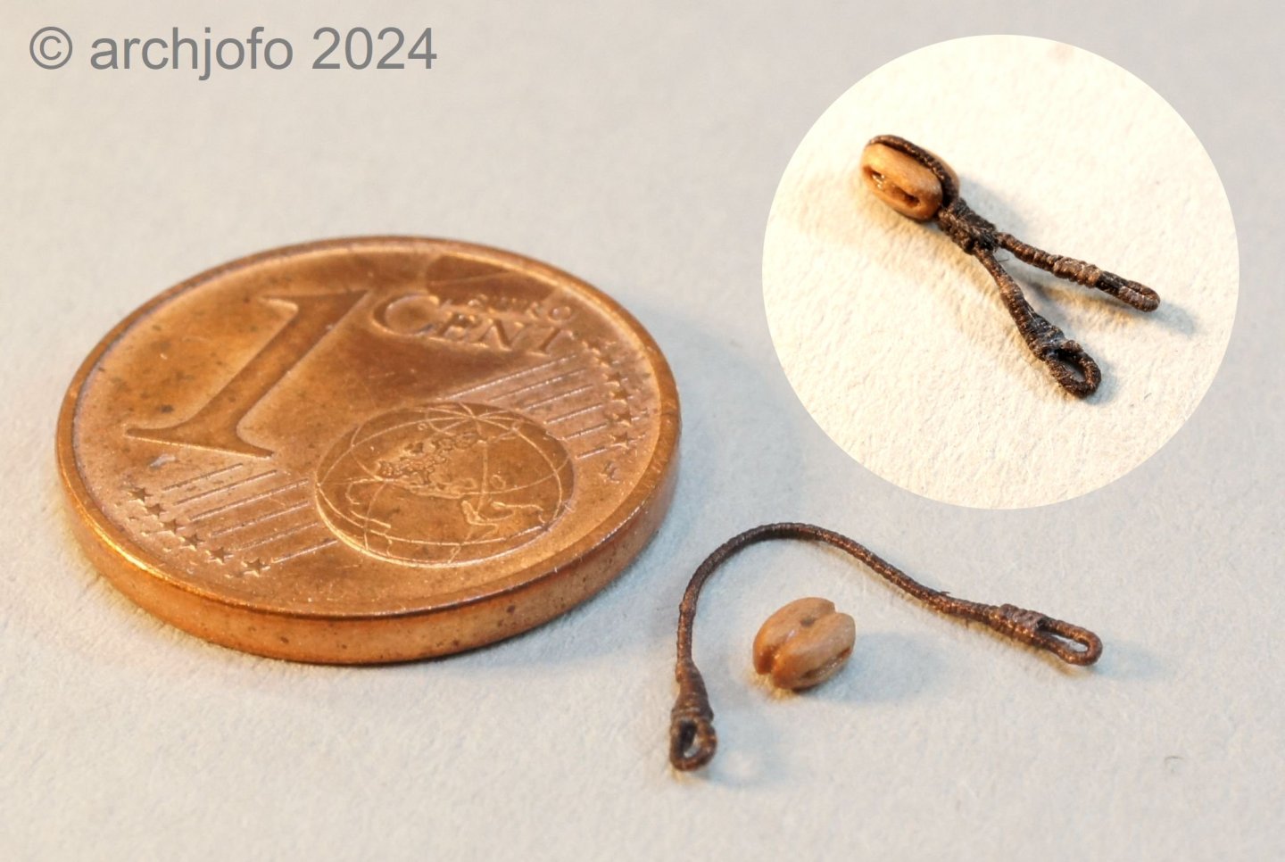
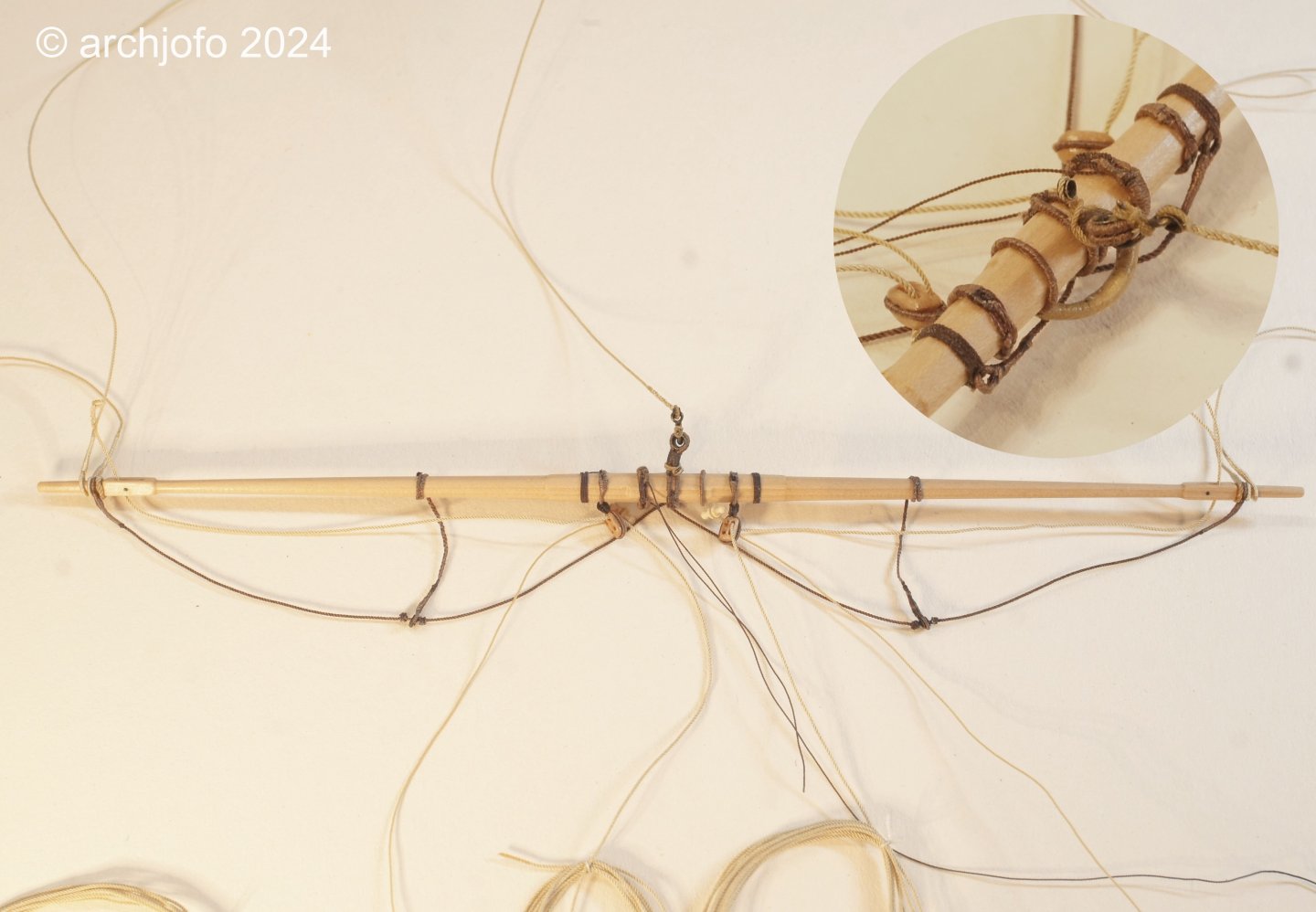
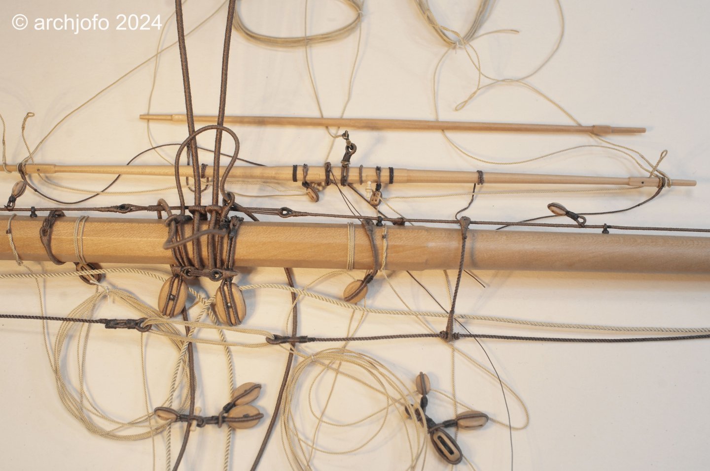
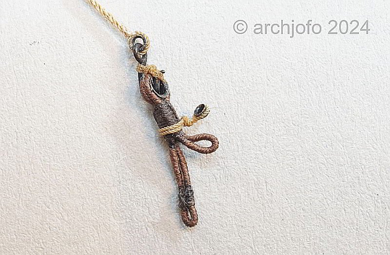
 Continuation: Further accessories for the topsail halyards, including leader (guide bar) - Gouvernail de drisse The leaders are another accessory required for the topsail halyards. This is a detail that is not always visible on all models, but is an important part of the rigging. Under the considerable force required to set a topsail, the halyard tends to twist and become unclear. To prevent this, the upper halyard block was guided to the topmast backstay with a guide bar and a swivel hook was used at the channel. In the following, I have compiled a list of different types of guide bars that were used towards the end of the 18th century and in the 19th century. However, they all served the same purpose. For my model of La Créole, I naturally used the original Parisian model and the Manuel du Gabier. Compared to the original model, however, I added the swivel hook and made a longer strop, which made it possible to keep the lower block free of the bulwark and the tackles of the backstays. I then executed this rigging arrangement according to the following drawing. I made all the elements in advance to see how it would look overall. If the “prototype” fits, all the other necessary parts for all the topsail halyards will be made. Provisionally arranged, it then looks like this: I had already made the swivel hooks in connection with the stay tackles, so that went quickly. Making the guide bar was also not a big job. For the sake of strength, I hard-soldered all the connections of these components. It was a little more difficult to attach the guide bar to the topsail halyard. It would be unsightly if over-dimensional knots were to impair the filigree structure. I have already considered how I can then attach the halyard to the model. In this respect, I have to finish one side completely as shown and then serve the appropriate places in advance, such as the passage through the tye blocks and the other end of the halyard. Then the rope of the topsail halyard is pulled through the tye blocks, then the eye with thimble is completed, taking the upper block into account. Finally, I have to dress a short remaining section freehand and attach the guide bar. Certainly not an easy task on the model, but people also need certain challenges ...😊 To be continued ... PS: I don't know if the term "guide bar" is correct? I would be grateful if someone could tell me the correct term.
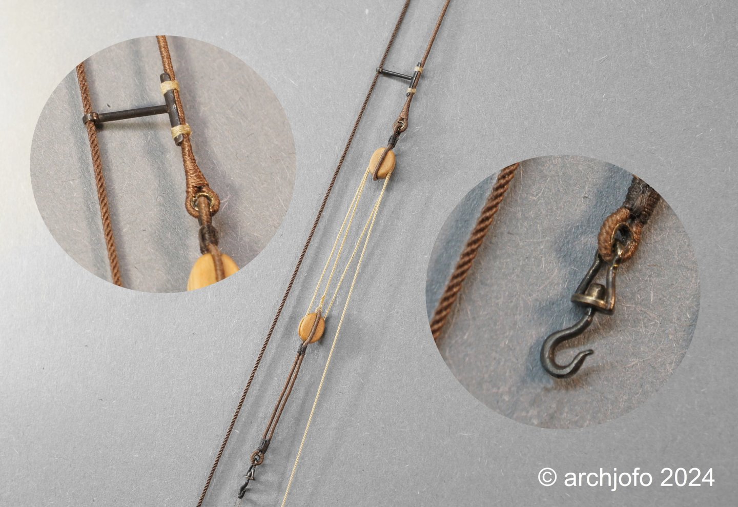
-
@Dziadeczek Hello, of course you can ask questions and I'll be happy to answer them. This forum is intended to be a forum for professional exchange. I use serviceberry for the blocks. This wood is very similar to pear wood in terms of structure, fine grain and hardness.
-
@davyboy Hello Dave, Thank you very much for the hint, but unfortunately I couldn't find anything about it in my German version. I have finally found something on the subject of attaching the standing parts of braces to stays. First of all, I will show you a historical example of a knot: Source: Atlas du Génie Maritime It is not clear what type of knot it is. On the other hand, you can see a possible way of doing this on the mainstay of the replica of the L'Hermione: Source: Internet (excerpt) If I am not completely mistaken, this is a stopper's hitch or rolling hitch (formerly also called a magnus hitch), in French Noued coulant or Amarrage a' fouet. I know from the official website for the L'Hermione that the riggers use the following when rigging the L'Hermione: also based my work on the book "The Ashley Book of Knots", which also shows this type of knot. But they are also mentioned in the Biddlecomb, Lever or Steel, as well as in F. A. Coste (French technical literature from 1829). However, I cannot find any clear assignments for a specific purpose here. It is always kept rather general. But ultimately it does seem plausible to me to attach these standing parts of the braces in this way.
-
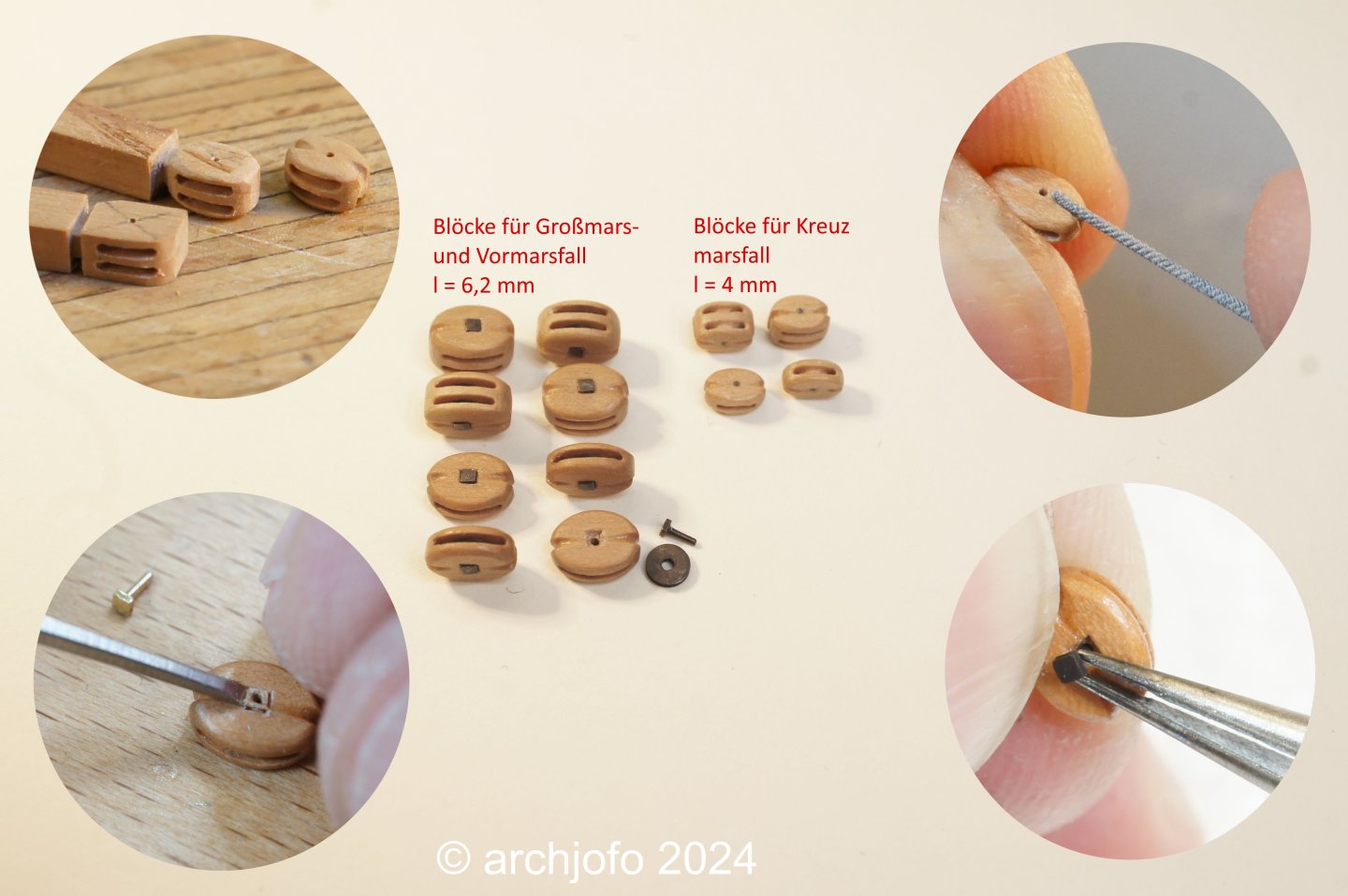
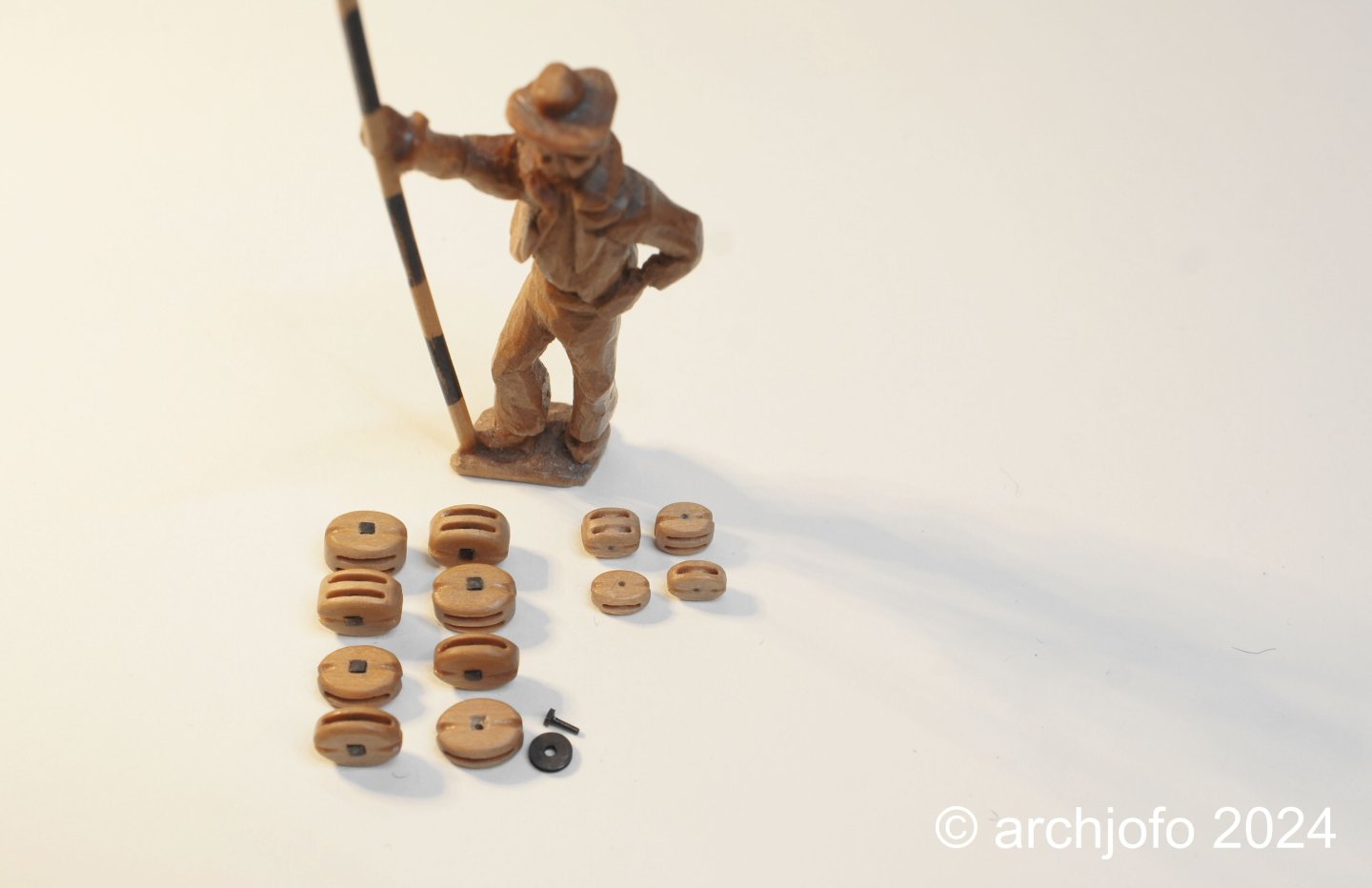
Continuation: Making more blocks - topsail halyards As already mentioned, there are still a few blocks to be made, including for the topsail halyards. Source: Monograph on La Créole by Jean Boudriot I made these single and double blocks again using the method shown so far. This method is not the most effective and has little to do with series production, but I am quite happy with the result. In the next step I will complete the tackles of the topsail halyards (strops, ropes, hooks, eyebolts, spacers, etc.). See you soon...
-
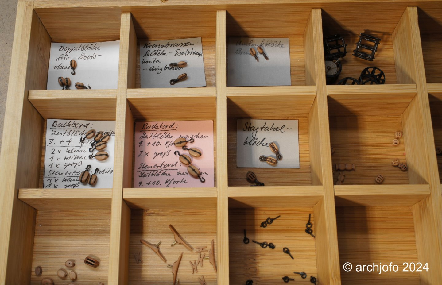
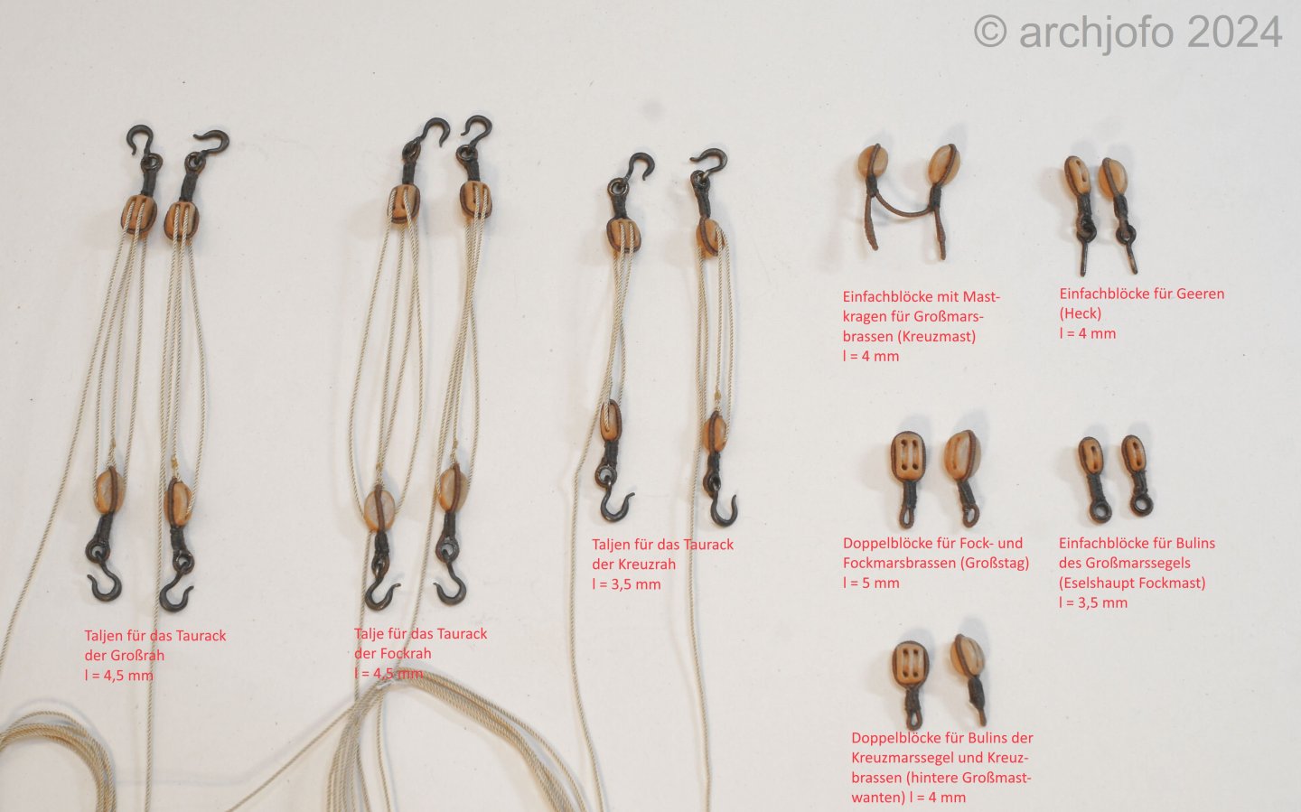
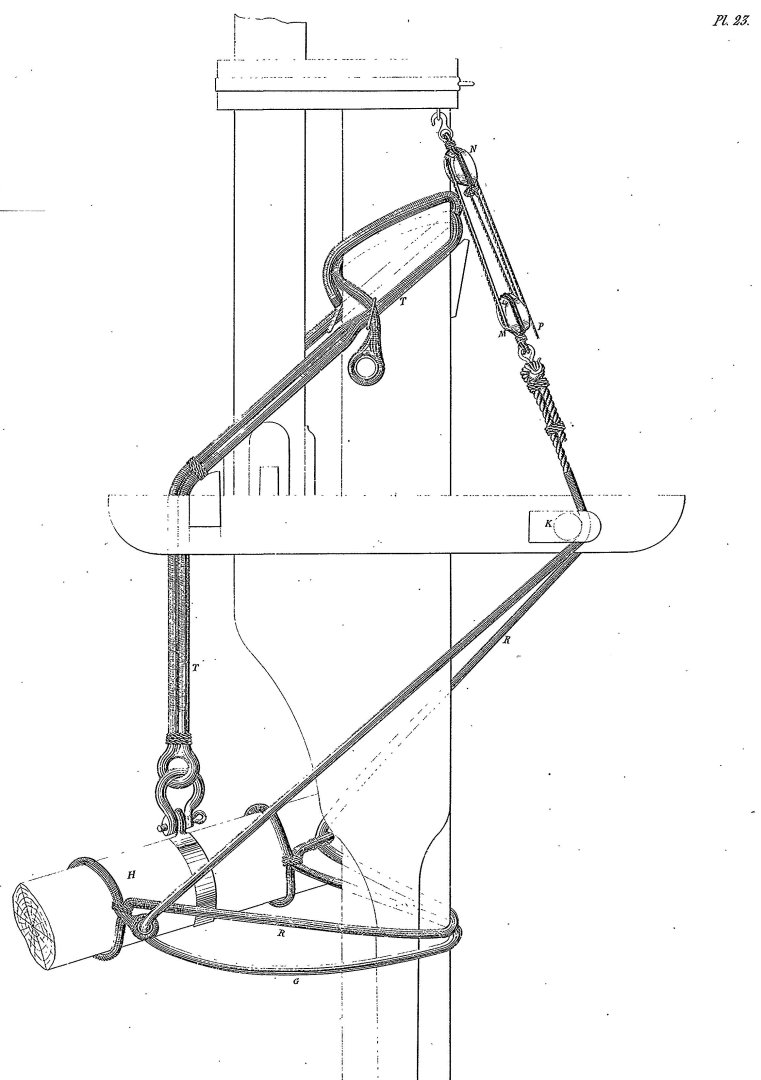
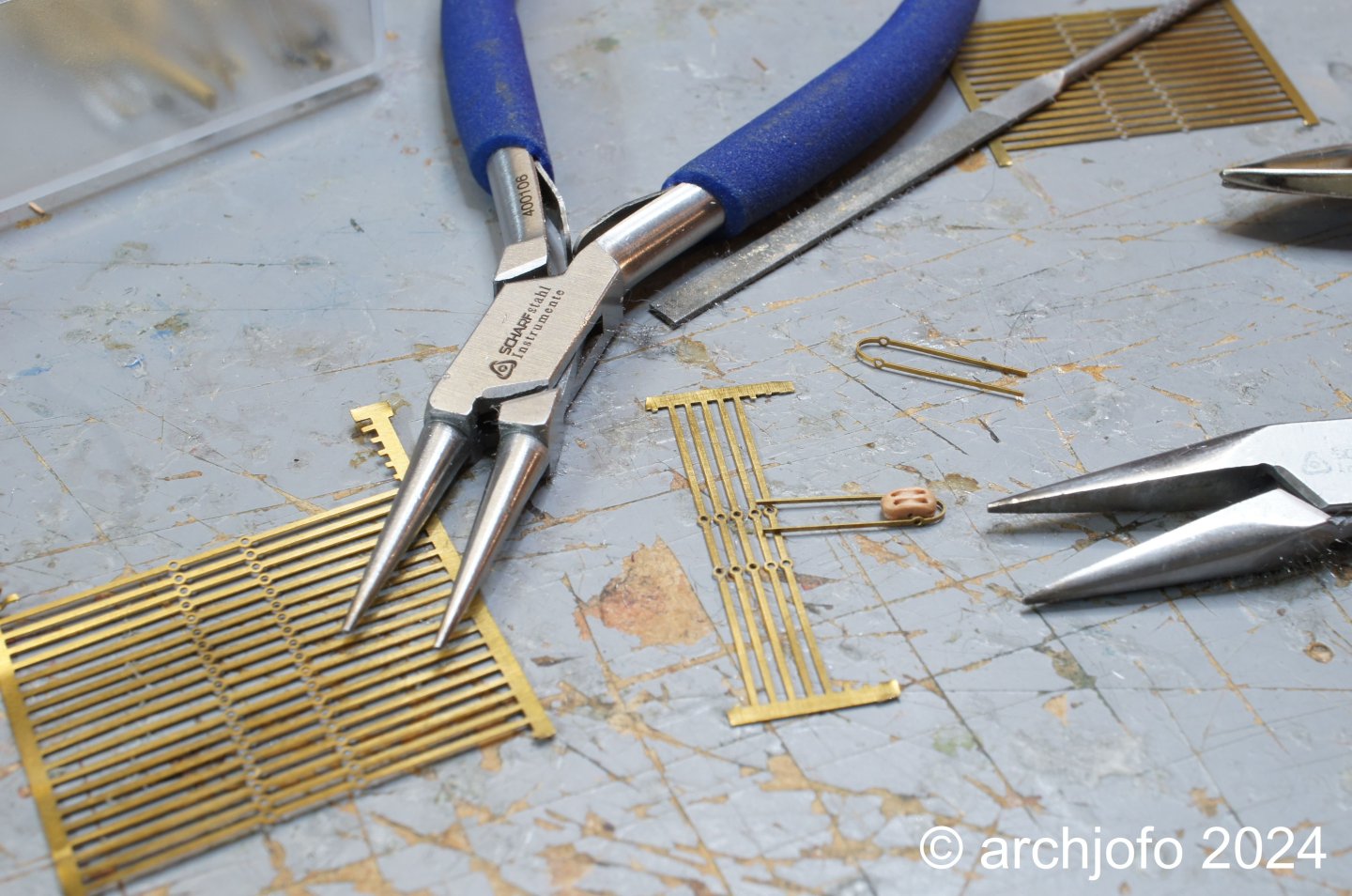
Hello colleagues, Thank you in advance for your kind feedback. When I started the final rigging, I was a bit too optimistic...😁 Making more blocks for tackles for truss pendants, redirecting the braces, bowlines, etc. Before I take the model out of the dust cover as announced and start the final rigging, I thought that it would be more clever to make the missing blocks so that I can then make the craft room dust-free. This required a lot of research to get some clarity about various design details. In particular, it was about making the tackles for the truss pendants of the lower yards. The truss pendants themselves are already attached to the lower yards. Later, when attaching the lower yards, the ends of the truss pendants have to be guided through the sheaves on the trestle trees. Then thimbles have to be tied into the ends, to which the rope tackles can then be hooked. This drawing from the Atlas de Génie Maritime illustrates the principle. Source: Extract from the Atlas du Génie Maritime Pl. 23 These tackles and other blocks with corresponding strops and thimbles, depending on the use, can be seen in the following picture. Some time ago I also made a series of guide blocks, as shown below, which are hooked into the area of the belaying pin rails. Accordingly, there shouldn't be too many blocks missing now. So I will now look through the rigging again using the monograph in conjunction with the pictures of the original model that I have available in order to capture as many blocks as possible. The tackles topsail halyards spring to mind and there are certainly still some deflection and guide blocks missing from the upper rigging. With regard to the final rigging, I am wondering how the standing parts of the braces are correctly attached to the stays. There is certainly a specific way of attaching them (knots, banding, etc.). Unfortunately, I have not been able to find anything about this so far, neither in the specialist literature nor on the Internet. I would therefore be very grateful if you could give me some advice. To be continued...
-
@wefalck Hello Eberhard, After successfully completing the wonderful model of the "SMS Wespe" you have started another very interesting model building project. The shipbuilding background alone is very exciting. I'm looking forward to the continuation.
-
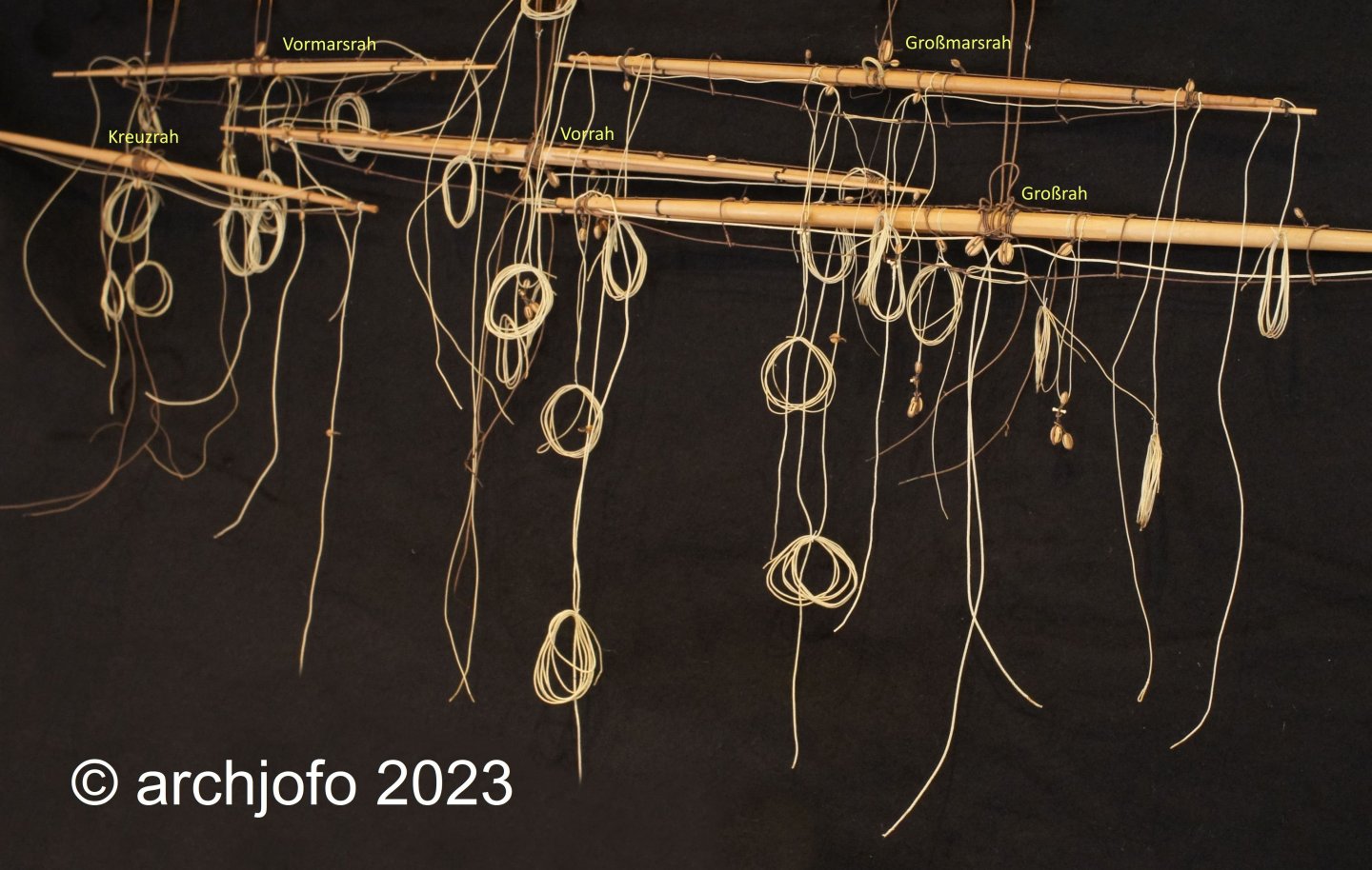
@druxey Hello, Thank you for your interest and positive response. @dvm27 Hello Greg, Thanks, yes, now it's the final stretch. Now I'm taking the corvette out of the dust cover where I stored it almost a year ago. Here you can see part of the yards again: Hopefully I'll be able to show more interesting pictures of the ship model again. At the moment I'm still wondering whether I should start attaching the yards and thus rigging from the back or from the front? I'd be open to tips!

-
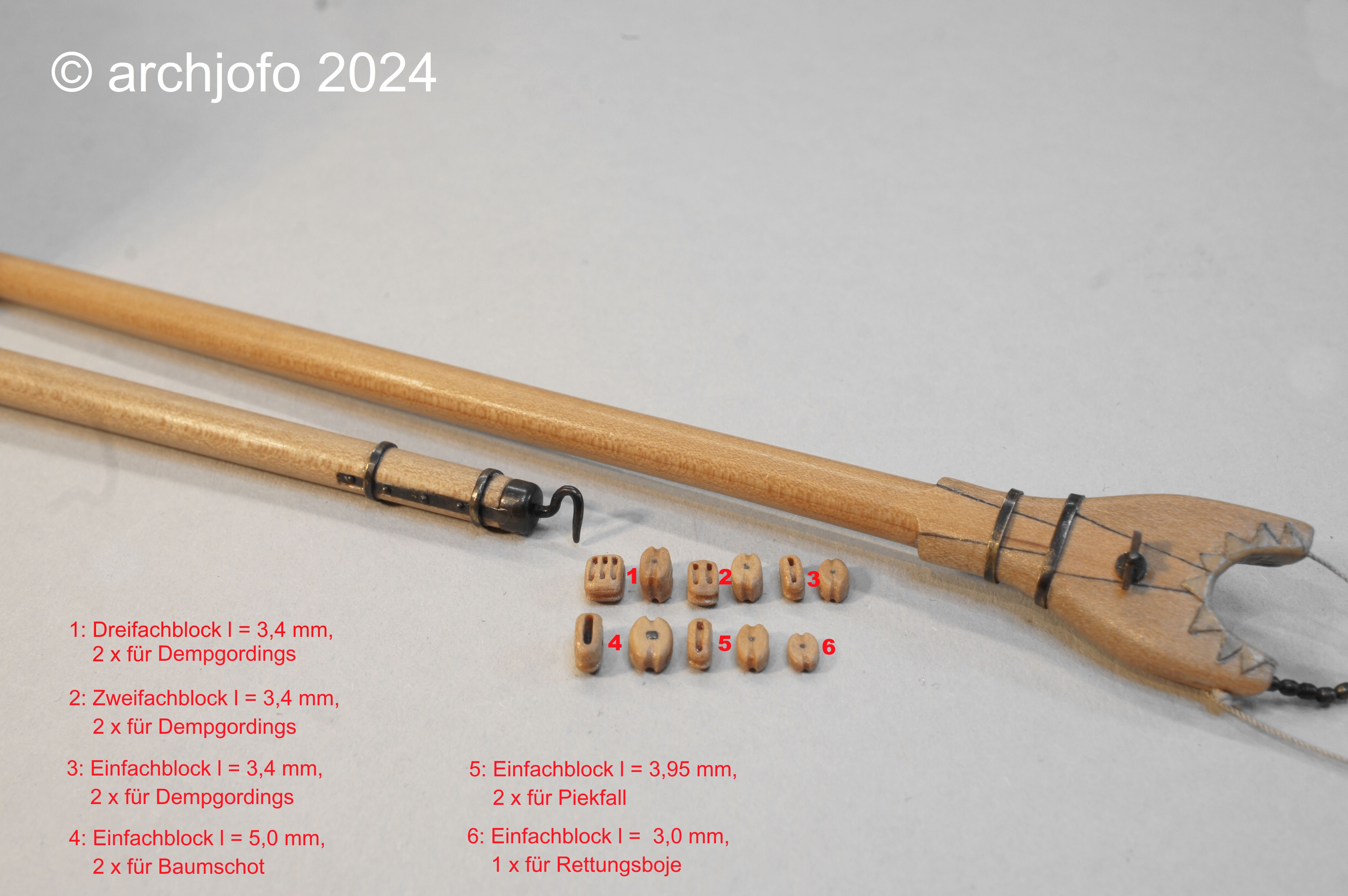
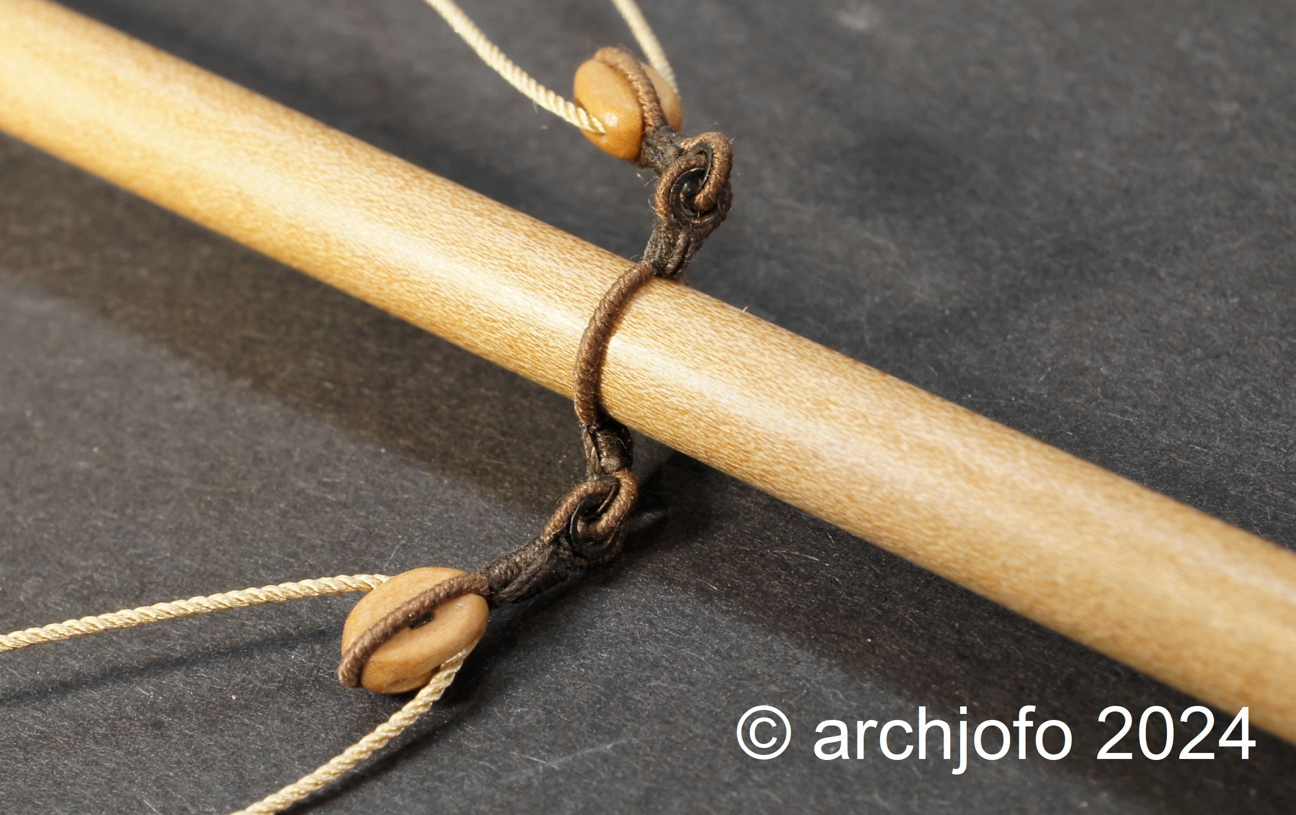
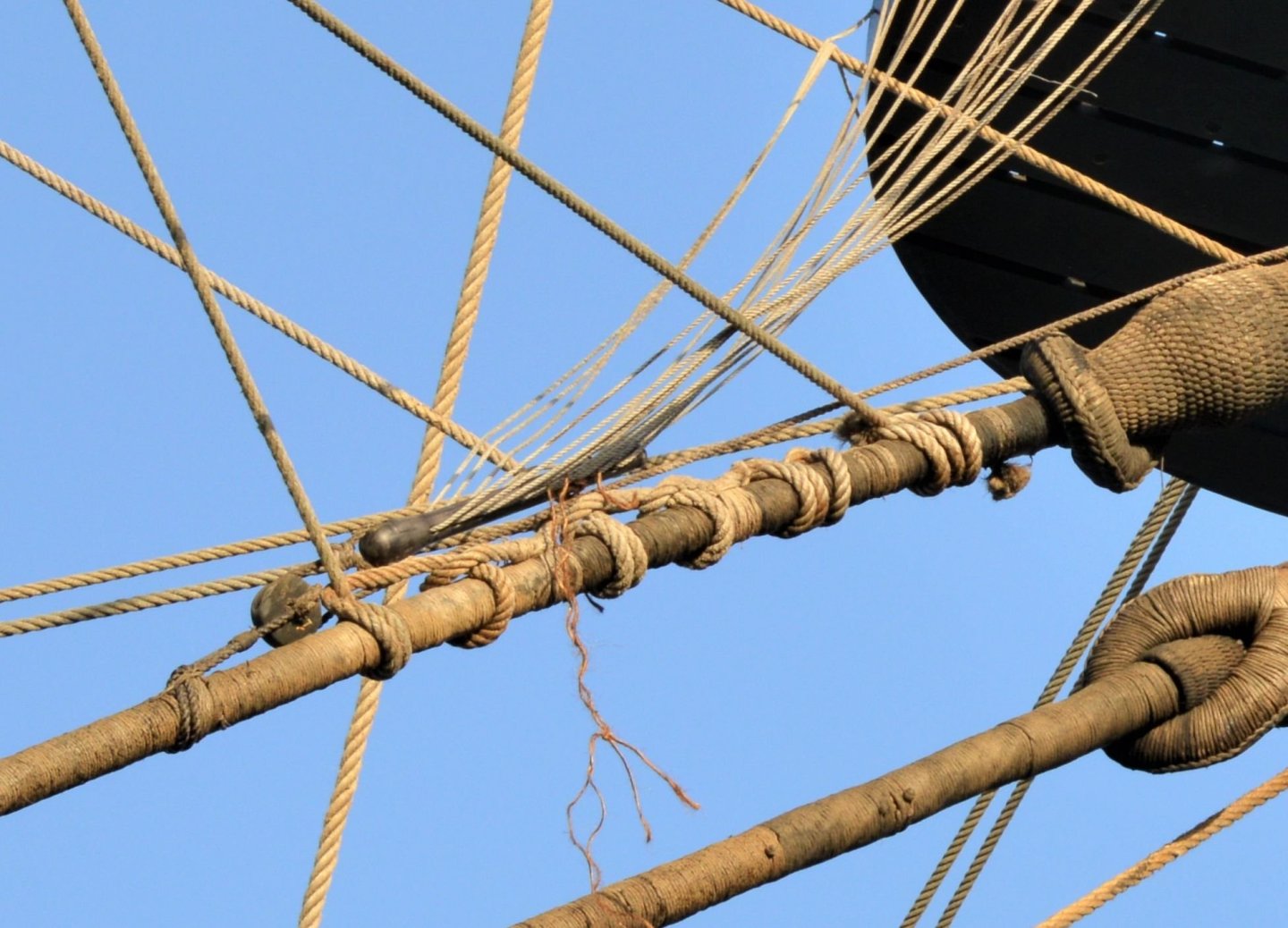
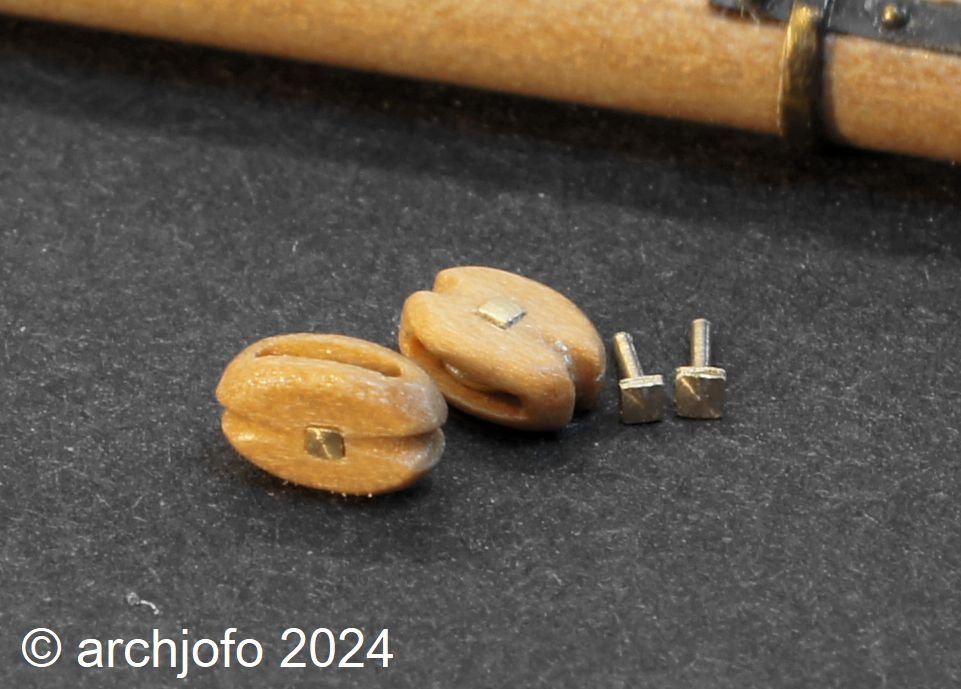
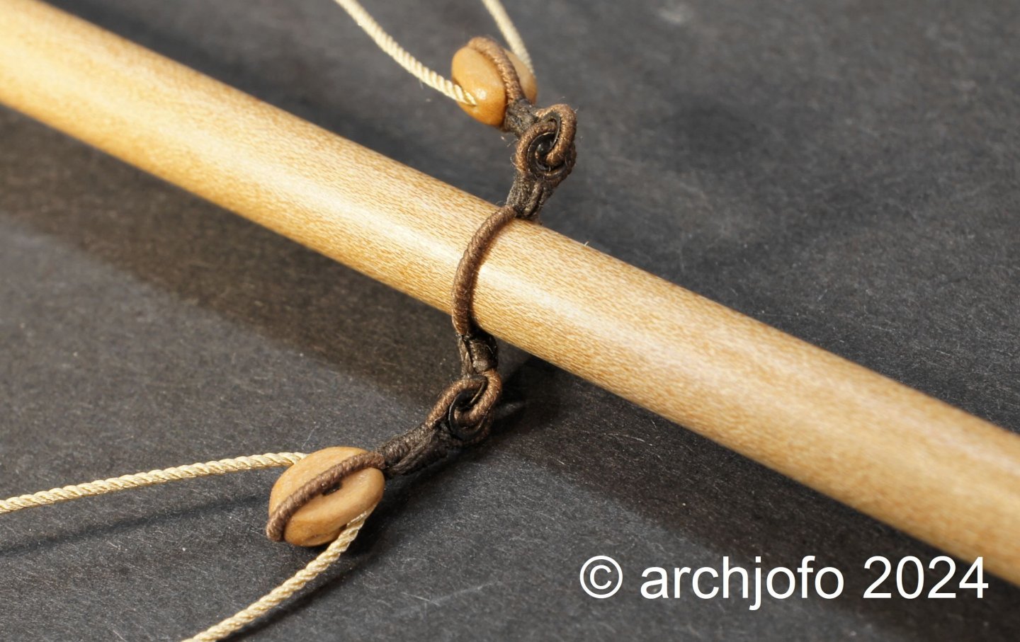
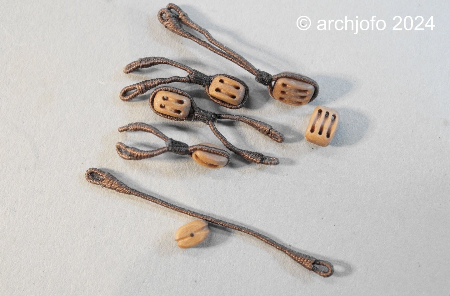
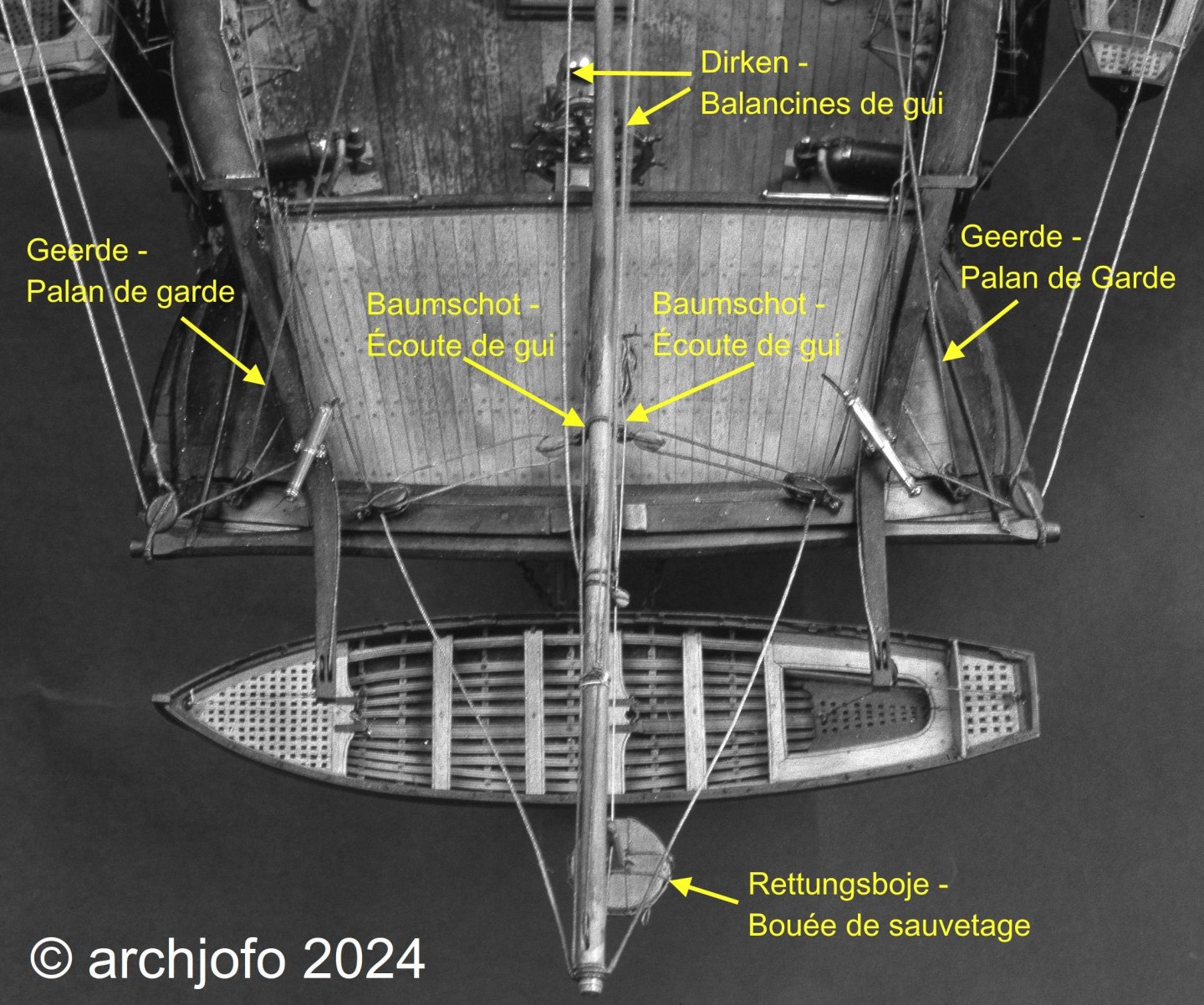
Hello, after a break I would like to continue with my construction report. First of all I would like to thank you for your interest and especially for the important tips on soldering. Through this exchange of information we all learn and develop our model-making skills. Thank you! Continuation: Equipment for the gaff and boom - boom sheets / Écoute de gui etc. In the meantime I was able to make the blocks required for the gaff and boom. The single blocks for the mainsheets were given brass discs. For the block axles with the square heads I made two smaller versions, the smallest of which was used because of the better scale, as can be seen in the following picture. The next picture shows a compilation of the blocks that are attached to the gaff and boom using strops. For the design of the mainsheet of the La Créole I based myself on the Paris model. There is one special feature to be mentioned in this context. The Paris model of the La Créole is not a mainsheet as one usually knows it. In principle, this mainsheet of the French corvette consists of two tackles, the standing parts of which are attached to the end of the boom and thus also contribute to stabilizing the boom in the form of boom strops (see photo). Apart from this model, I have never seen or heard of such a mainsheet, neither on contemporary models nor in the relevant specialist literature. To be sure that this form actually existed, I tried to find it in the contemporary specialist literature in the book "Manuel de gréement" by F. A. Coste, Paris 1829. And in fact, on page 147, in addition to the usual versions, exactly this special type is described. Source: Musée national de la Marine de Paris - La Créole The following rigging elements were then required, manufactured and attached to the boom: The next picture shows the partially rope stropped brail blocks, each double, for the gaff: Below is a picture of the rigging elements that have now been mounted on the gaff: The vangs are still missing, which will then be attached to the model when the gaff is assembled. As far as I know, these are placed around the gaff with a clove hitch. So now all the yards and spars of my corvette are equipped and ready for the final rigging. To be continued...

-
@Dziadeczek Thank you very much for this interesting information.
-
Hello, Thanks for the tip, I've heard of the process but don't know it in detail. Can you briefly explain to me how it works and what you need for it?
-
@Pirate adam @FriedClams Thank you very much for your interest and the nice comments. Also many thanks to all for the LIKES. Continuation: Peak halyard - Drisse de pic The peak halyard of the French corvette led over a double block with iron fittings and was probably hooked to an eyebolt on the cap des mizzen mast, similar to a depiction in the Atlas du Génie Maritime. Source: Atlas du Génie Maritime - detail I made the double block with a length of approx. 4 mm in the usual method from service tree. The fittings were made in the manner already described from partially prefabricated etched and cast brass parts. The hard soldering of the hook is a tricky job, but I've managed it in the meantime with some practice. The biggest problem is destroying the part with too much heat from the torch. After adjusting the fitting to the block and soldering in the hook, the solder joint was sanded clean. The next two pictures show the finished double block with the eyebolt, which will later be attached to the cap. And last but not least, a picture of the hooked double block. Now there are still a number of different blocks to be made for the gaff and the boom. To be continued ...

-
@druxey Thank you for your interest and everyone else for the LIKES Continuation: throat halyard – Drisse de mat We continued with the manufacture of the block strops for the throat halyard. The hook was tied into the lower double block with a thimble. The halyard with a diameter of 0.46 mm (ø 2 mm in the original) was attached to the block strop of the upper block using an eye splice. I then quickly attached the gaff to the finished throat halyard, as can be seen in the following pictures. To be continued...

-
Completion of the gaff with throat halyard - Corne avec drisse de mat As already announced, I am currently working on the gaff rigging. To do this, it is necessary to add additional equipment to the gaff. I already made these some time ago. However, in addition to the metal block (signal haylard block) for the flag line on the gaff peak, a sheave for the sheet of the gaff topsail had to be installed, as can be seen in the following picture. I also had to fit the jaw of the gaff with a heavy eyebolt. This eyebolt, which is under tension, was secured from below with a wedge. According to the information available to me (monograph, pictures of the Paris model), the throat halyard of the French corvette looked as follows: The twin blocks required for the throad halyard have a length of 5.6 mm. As before, I use real disks for this size. I have also tried to reproduce the block axis as in the original. I will continue soon ...
-
Equipment of the mizzen royal yard - Vergue de cacatois de perruche With the outfitting of the mizzen royal yard, the smallest yard of the corvette, this chapter - outfitting the yards - now comes to an end. The mizzen royal yard of the model has a length of approx. 11.3 cm and a thickness of approx. 2 mm in the middle. The tye has a diameter of 0.25 mm. For the block slings I used ropes with a diameter of 0.25 mm, which were served. The results can be seen in the two pictures: I am currently researching the equipment for the gaff rigging. There are still a lot of details to clarify. See you soon ...
-
Very clean and precise work, and at this scale. You have my full admiration for that. This will be an extraordinary and wonderful model.
-
This is extremely clean and precise work. A wonderful model!
-
@druxey @albert Many thanks for your interest and encouragement, and thanks to everyone for the many LIKES. In the meantime, the constant rain here in Bavaria is getting on my nerves. On the other hand, I can spend more time building models again, so I can show you the latest results: Equipping the fore royal yard - Vergue de petit cacatois I continued with the equipment of the fore royal yard, analogous to the main royal yard. The fore royal yard still has a thickness of around 2.2 mm in the middle. The first picture shows the attached tye and parral. The clew line blocks that had already been produced were then fitted with served block strops and attached to the yard. This was followed by the final fitting of the yard with the lifts, braces and clew lines. As already mentioned, I will not be attaching any sails to this model. Accordingly, I will later connect the clew lines of the royals to the sheets without the corners of the clews using the toggles. Last but not least, a picture with the center section of the main yard for size comparison. To be continued ...

-
Admirable carpentry work, absolutely clean and precise. It's interesting to see how the Corvette's well-shaped hull comes into being.
-
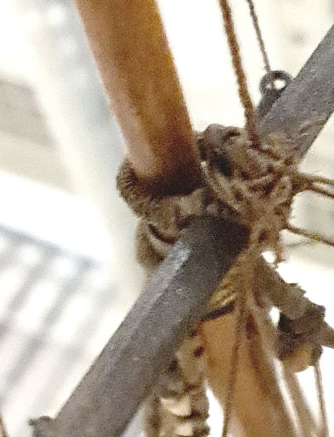
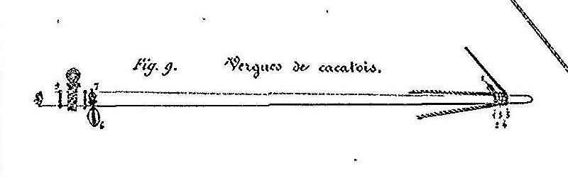
@Thukydides Thank you for your nice comment, and everyone else for the many LIKES. Equipment of the main royal yard – Vergue de grand cacatois The royal yards are on the 4th floor of the rigging. Since these yards on the La Créole were obviously equipped with lifts and braces, it can be assumed that they were already an integral part of the ship's rigging. In contrast, until the end of the 18th century, the royal sails were often hoisted together with the yards and flown as fair-weather sails only when necessary, i.e. without braces and lifts. To carry out the tyes for the royal yards of La Créole, I have photos of the original model at my disposal, which a restorer from the Musée de la Marine in Paris kindly photographed in the depot especially for me. You can't see much in the following picture of a royal yard of the Paris model, except that the tye is somehow knotted and doesn't have a hook like that of the togallant yards. Source: Musée national de la Marine de Paris – La Créole Source: Atlas du Génie Maritime In conjunction with the depiction of a royal yard from the Atlas du Génie Maritime and various other examples, the tyes may have looked like this. My model implementation or interpretation of the tye ø 17 mm (ø 0.35 mm in model scale) for the main royal yard looks like this: Next I made the parral. The royal yards receive a slightly simpler version of a parral, only served with ropes, without leather covering. This was followed by the production of the single blocks for the royal yards. These were used to guide the clew lines - The clew lines for the main royal sail had a diameter of 11 mm (in the model scale ø 0.23 mm), accordingly the blocks were around 13.5 cm long (in the model scale approx. 2.8 mm) according to the table in the monograph . After attaching the grommets as abrasion protection, the equipment of the main royal yard was completed by attaching the braces and lifts. We then continue with the fore royal yard. Sequel follows …


-
Continuation: Equipping the mizzen topgallant yard - Vergue de perruche After the small mishap, as reported, I have now made a new mizzen topgallant yard and fully equipped it. This means that the topgallant yard chapter can be put to bed until it is installed on the model. Here is a picture of the finished mizzen topgallant yard. And another picture with the tye. The next picture shows different yards of the French corvette in size comparison. In the center you can see the mizzen topgallant yard. Above it is the mizzen royal yard and finally the middle section of the main yard is shown below. The next step is to equip the royal yards with the necessary rigging elements. Then I'll finally have finished fitting out the yards. To be continued ...
-
Hello Greg, You're right, of course, making the rigging elements takes longer. I hope that I will soon be able to present the new mizzen topgallant yard ready and finished. At the moment I'm still researching how to carry out the tyes for the royal yards. I originally thought that these would be done in the same way as the topgallant yards, but obviously these are designed to be simpler.
-
Continuation: Equipment of the Cross Bramrah – Vergue de perruche A moment of inattention results in the following: At the broken point the mizzen topgallant yard is just 1.9 mm in diameter. Annoying, but gluing is not an option. Sequel follows …
-
I would like to congratulate you on the completion of this wonderful model. This is a masterpiece, model building art at the highest level. Thank you also for letting us participate in the construction with your report.
-
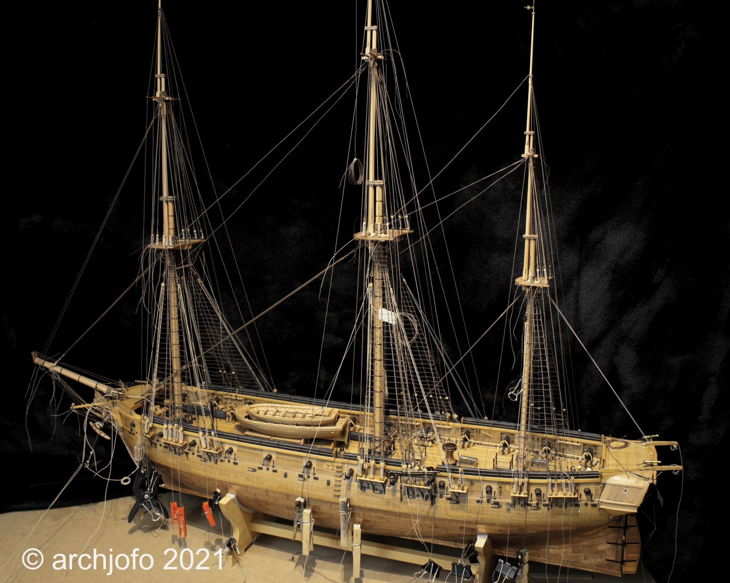
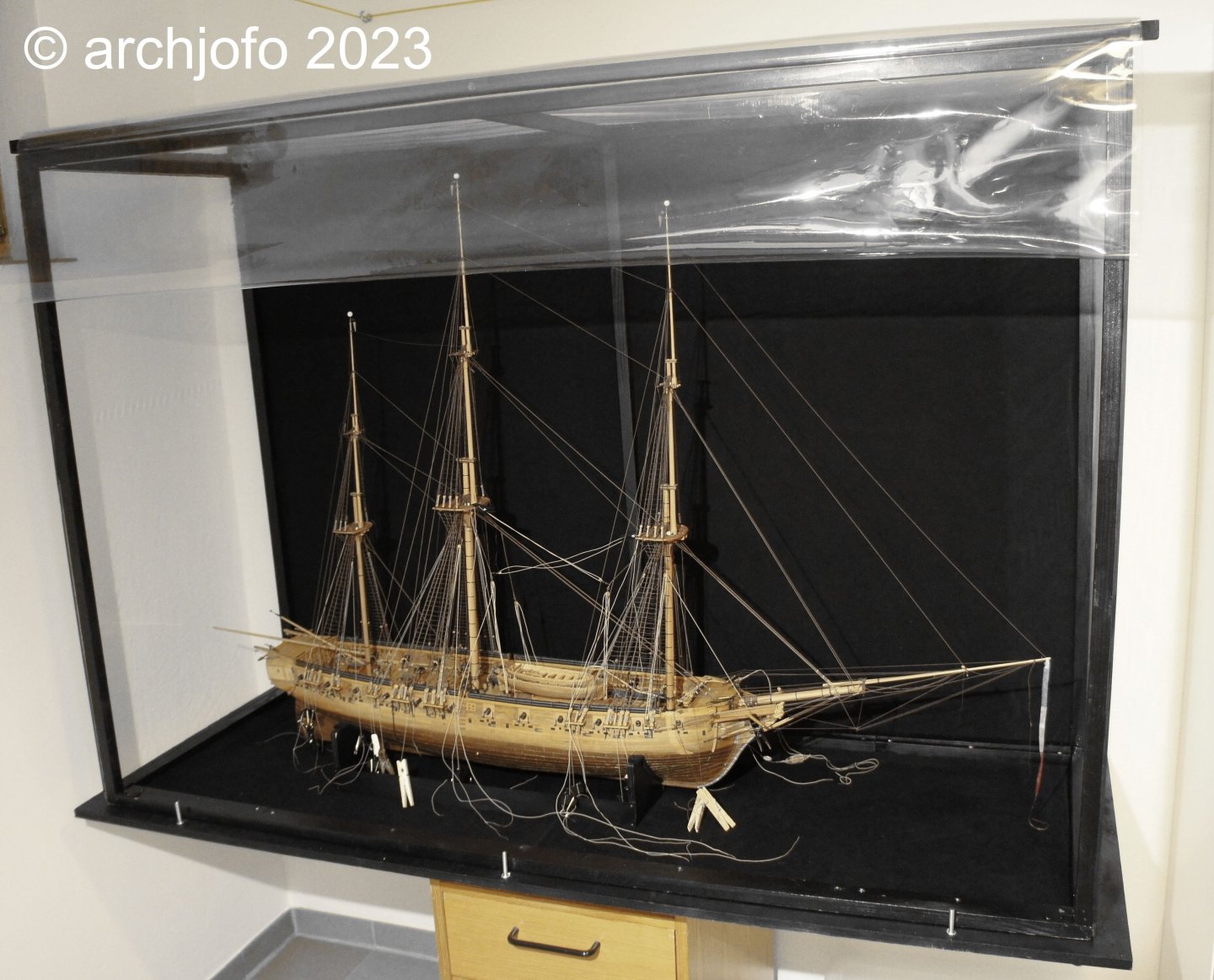
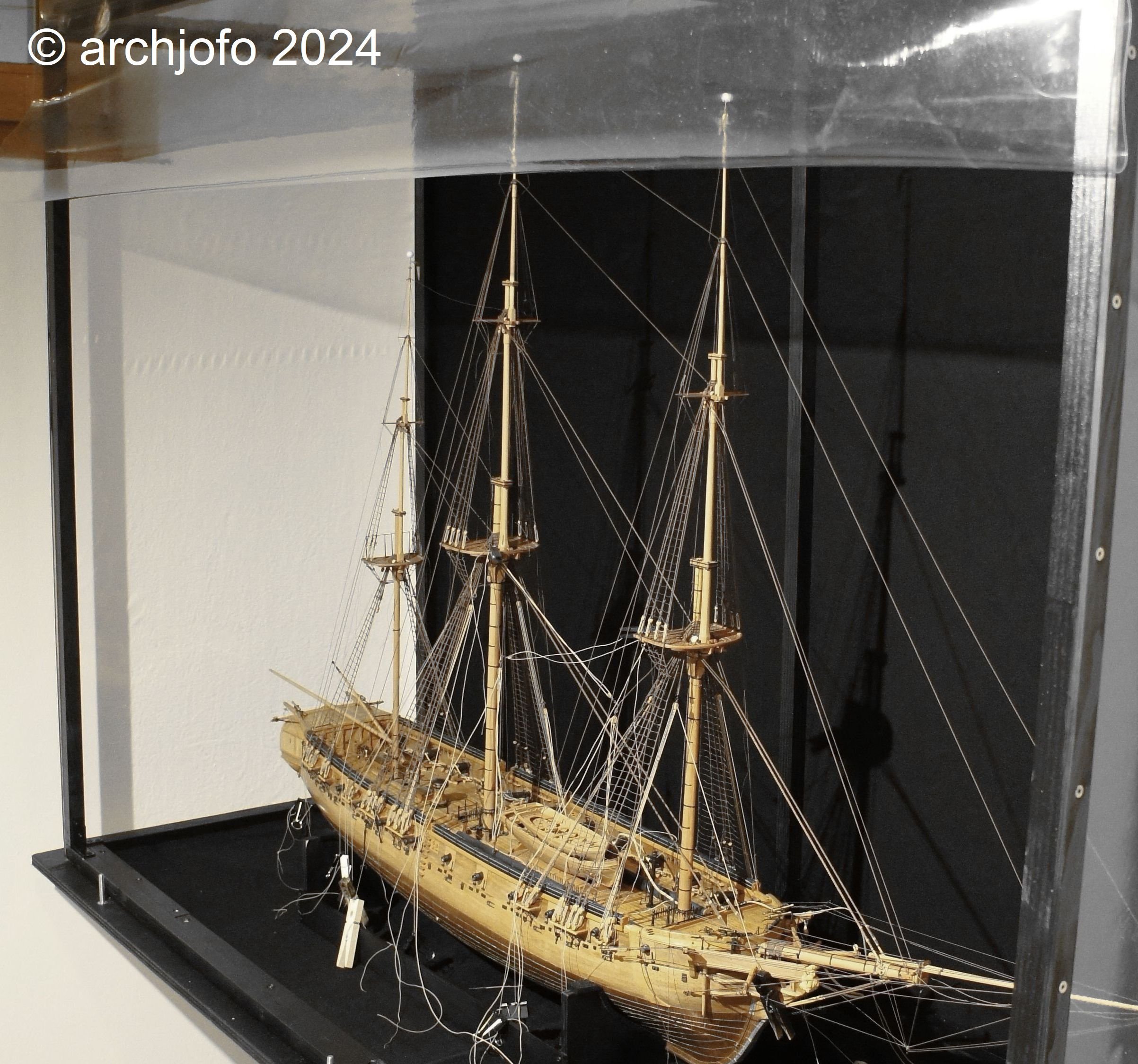
Hello, A while back, I captured some general shots of the model. It remains under a dust cover while I´m outfitting the yards. Regrettably, I don't have any recent pictures available right now.