
HOLIDAY DONATION DRIVE - SUPPORT MSW - DO YOUR PART TO KEEP THIS GREAT FORUM GOING! (Only 20 donations so far - C'mon guys!)
×

archjofo
-
Posts
1,495 -
Joined
-
Last visited
Content Type
Profiles
Forums
Gallery
Events
Everything posted by archjofo
-
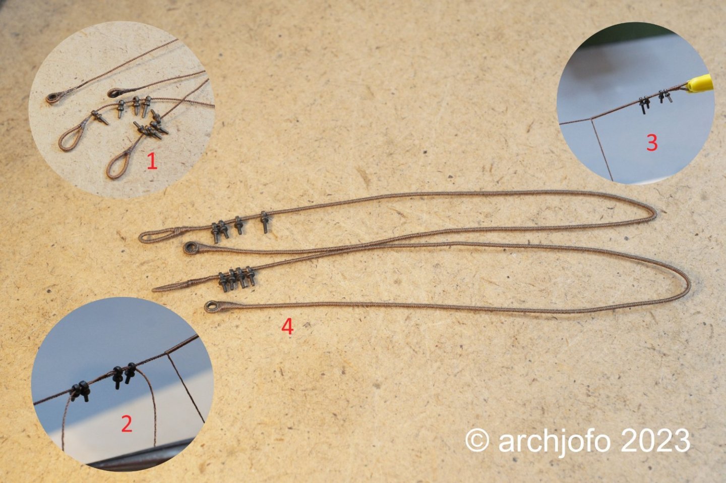
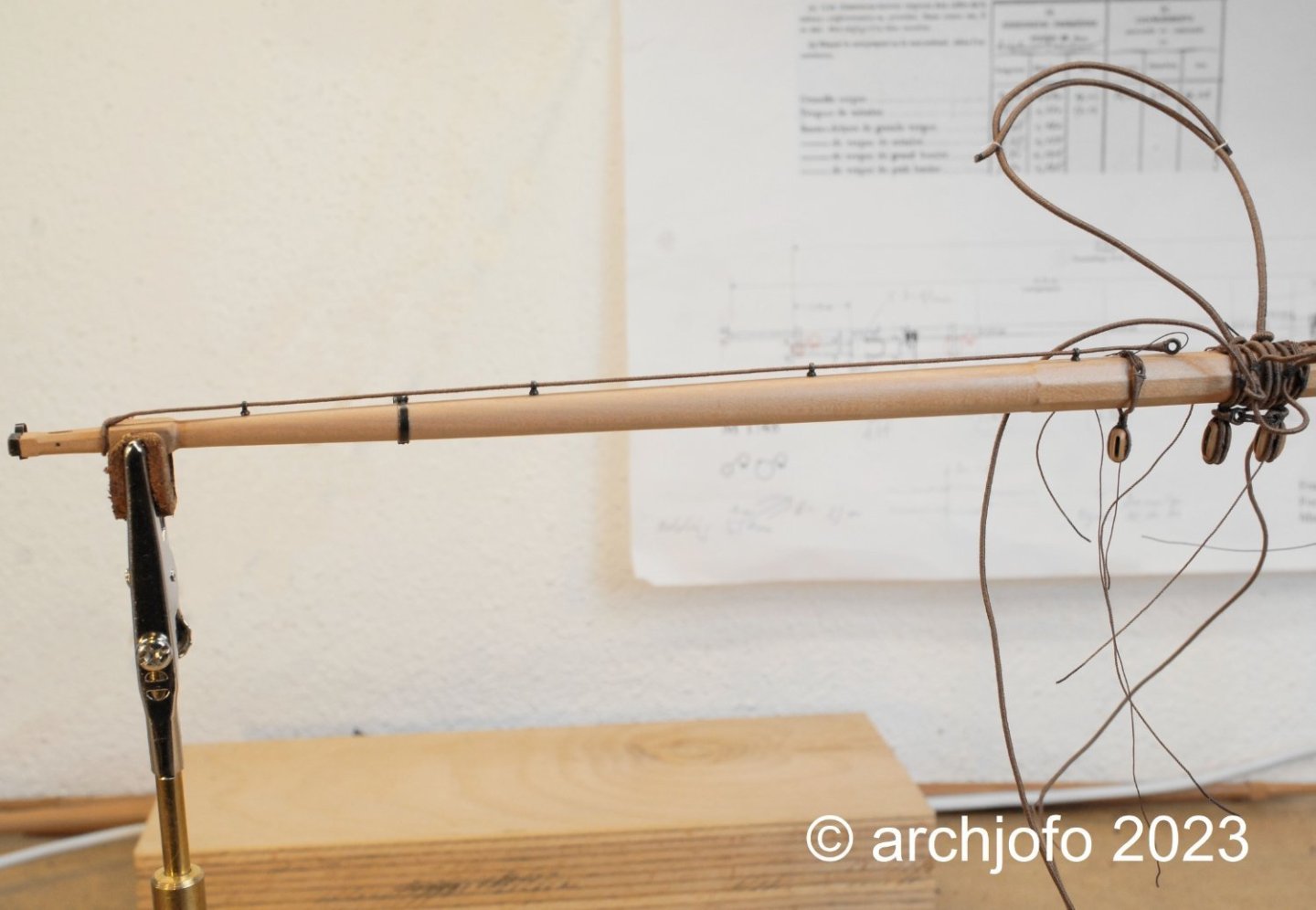
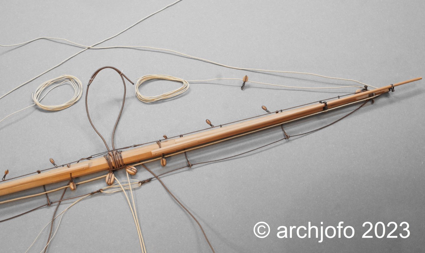
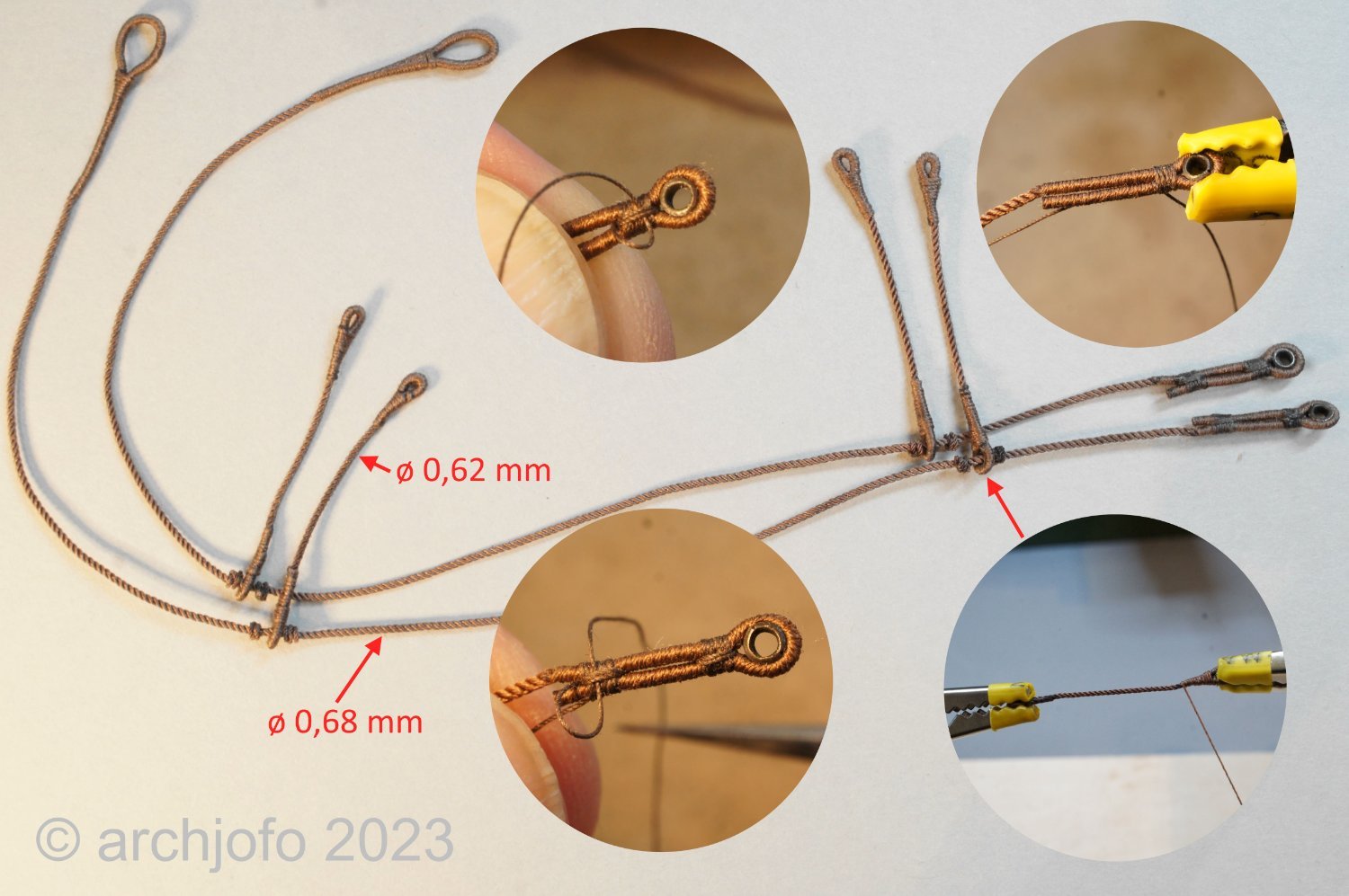
 @jdbondy @matiz Thank you very much for the nice comments. Thanks also to everyone else for the many LIKES. Hello fellow colleagues, back from Italy I escaped straight to the cool basement shipyard ... 😁 But apart from a few "finger exercises" I didn't get much done. I guess I have to "groove in" first, to put it drum-wise... 😁 Continued: Equipment of the fore yard -footropes and stirrups - Marchepieds et étrier In the meantime, the footropes and stirrups for the fore yard have been completed. With the help of the following photomontage I just want to give you a few more insights into the production of the details. On the next picture I show the current equipment level of the fore yard, where not too much is missing anymore. Up soon ...
-
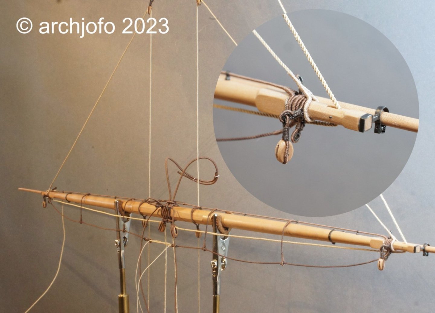
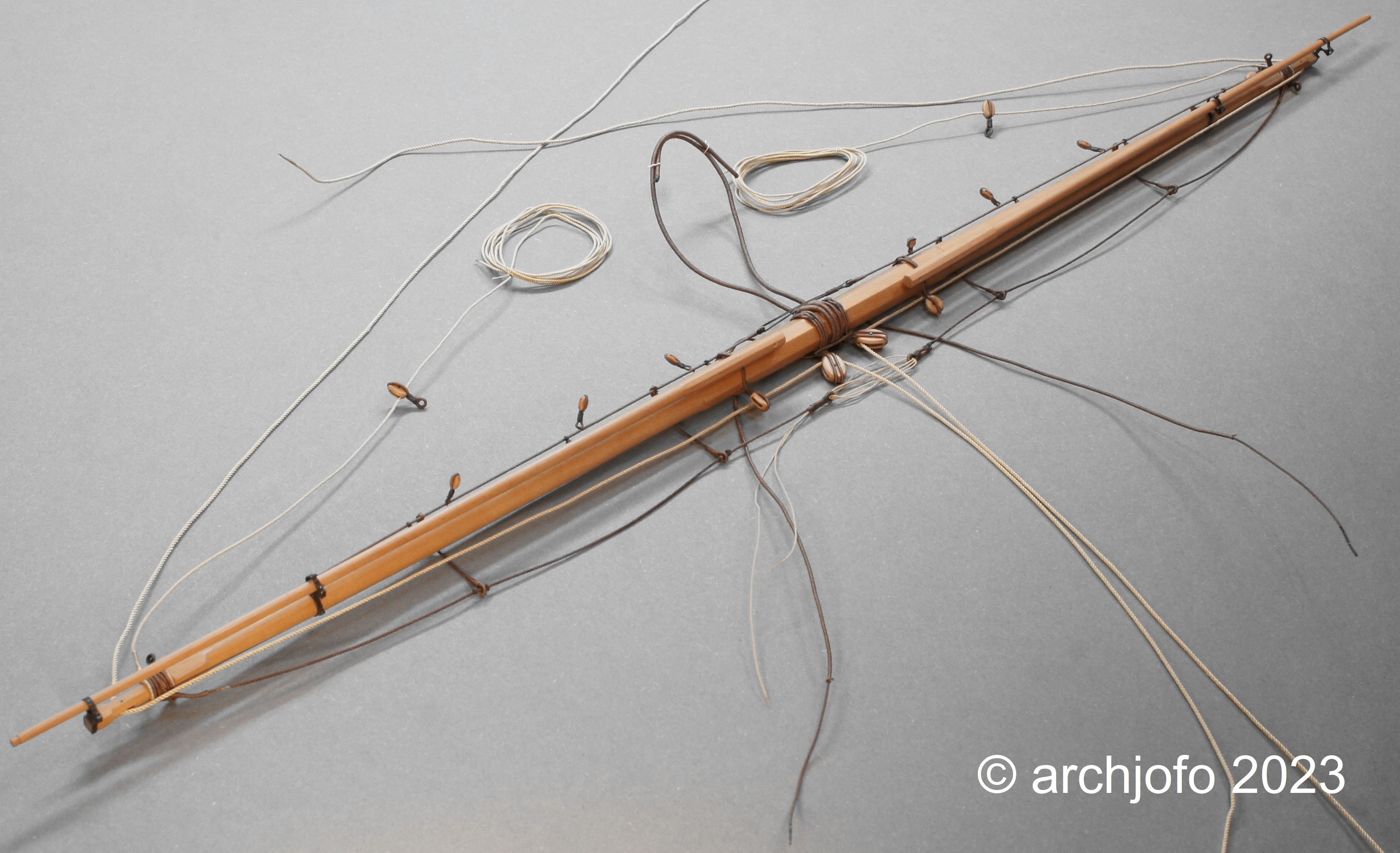
@wefalck That is very true, and I think that one or the other was involved with a specific work. @dvm27 Glad I could give you a suggestion. That is an honor for me. @druxey Glad you like it. The rose lashings looks more difficult than it actually is. Just give it a try. @Gahm I hope not ... 😁 Thanks to all for the interest and the LIKES. Continuation: Equipment of the fore yard - Jackstay / Filière d`envergure; Blocks for buntlines and clewlines / Poulies de cargue fond et poulies de boulin I would like to explain the installation of the jackstay in a little more detail using the fore yard as an example. According to my research and the Paris model, the jackstay was completely served to obtain the required stiffness. The eye splices for the yard arms and the thimbles of the tackle in the center of the yard were also served. How to implement this for the model in conjunction with the eyebolts? The solution is a bit tricky, but quite feasible, as shown in the following photo collage. I think the pictures are so far self-explanatory. The assembly on the yard, on the other hand, was very easy to accomplish. The rope for the tackle was pulled in and lashed as well as the blocks for buntlines and clewlines were already attached. To be continued ...
-
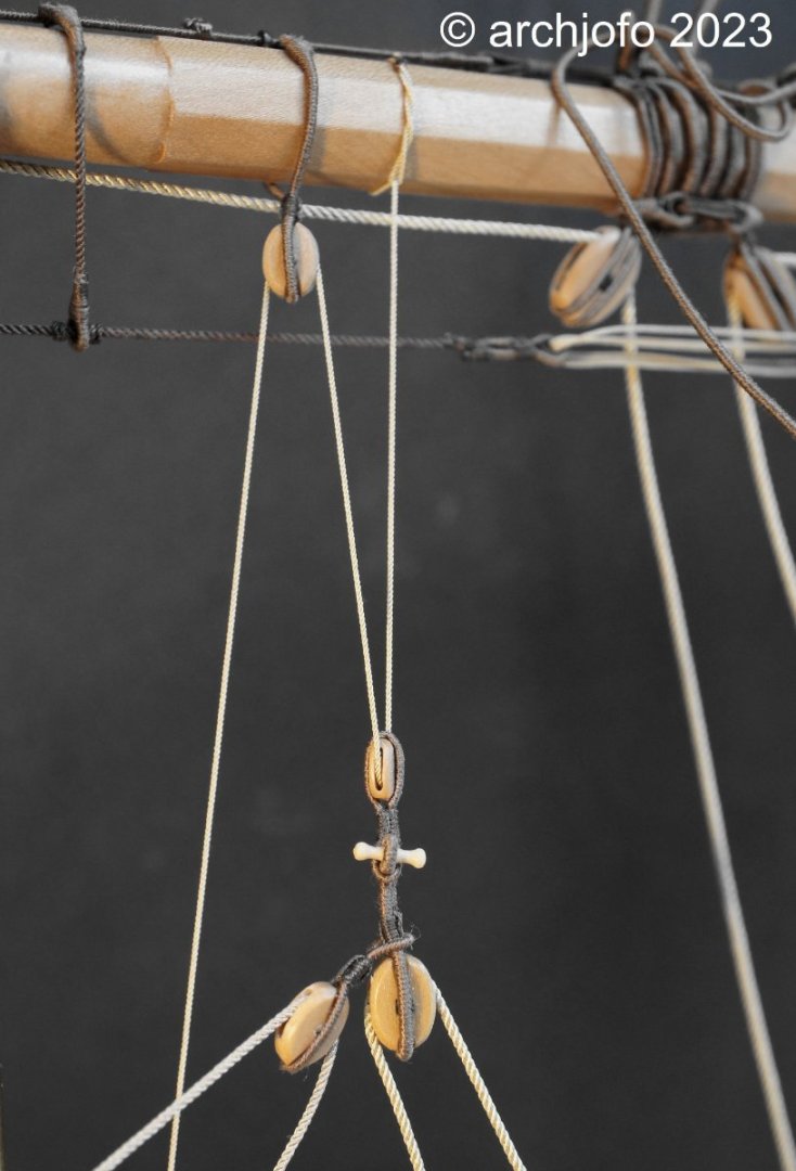
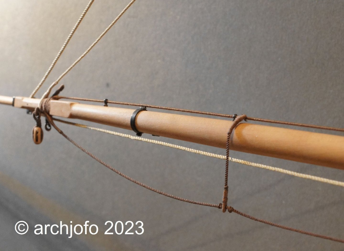
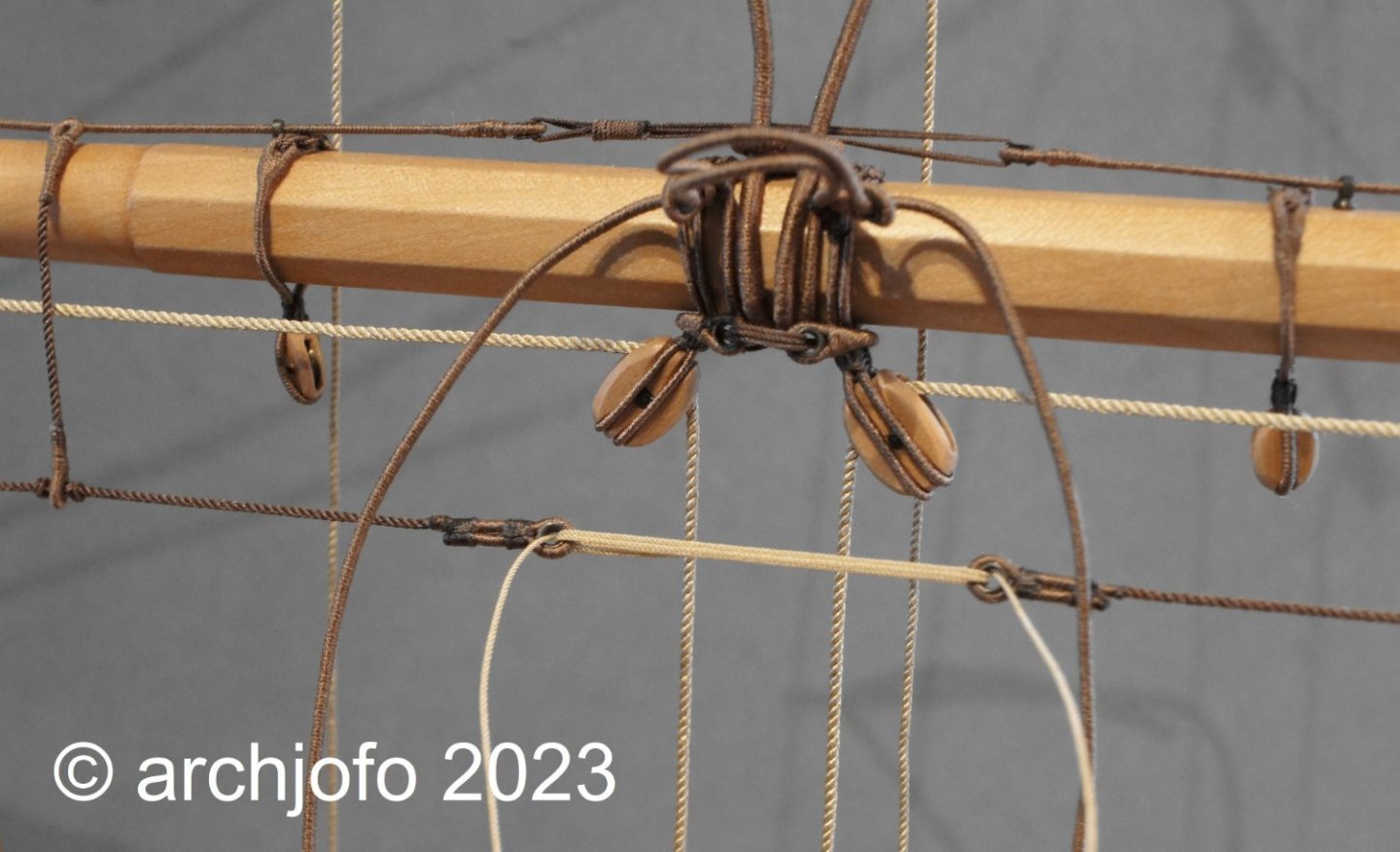
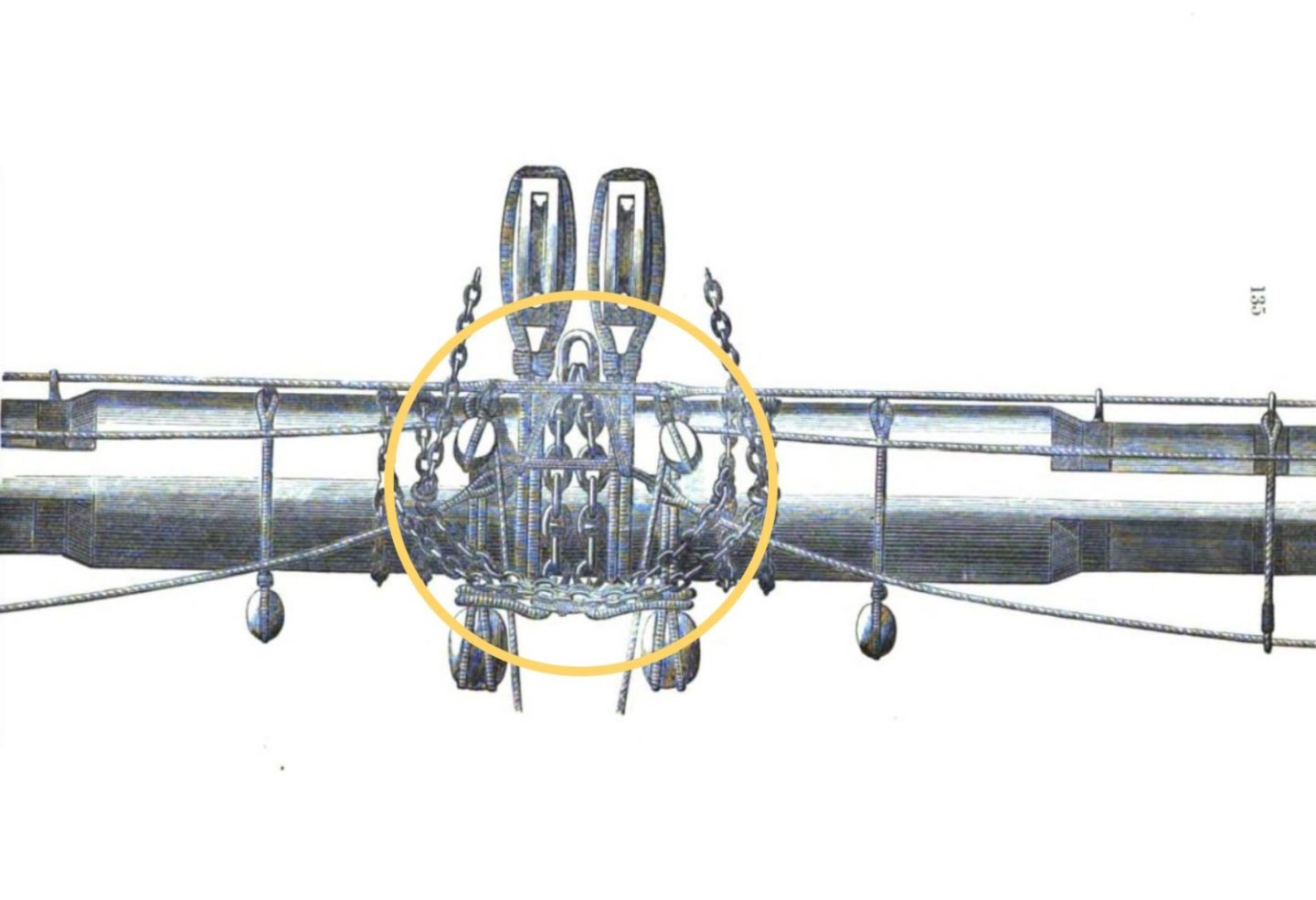
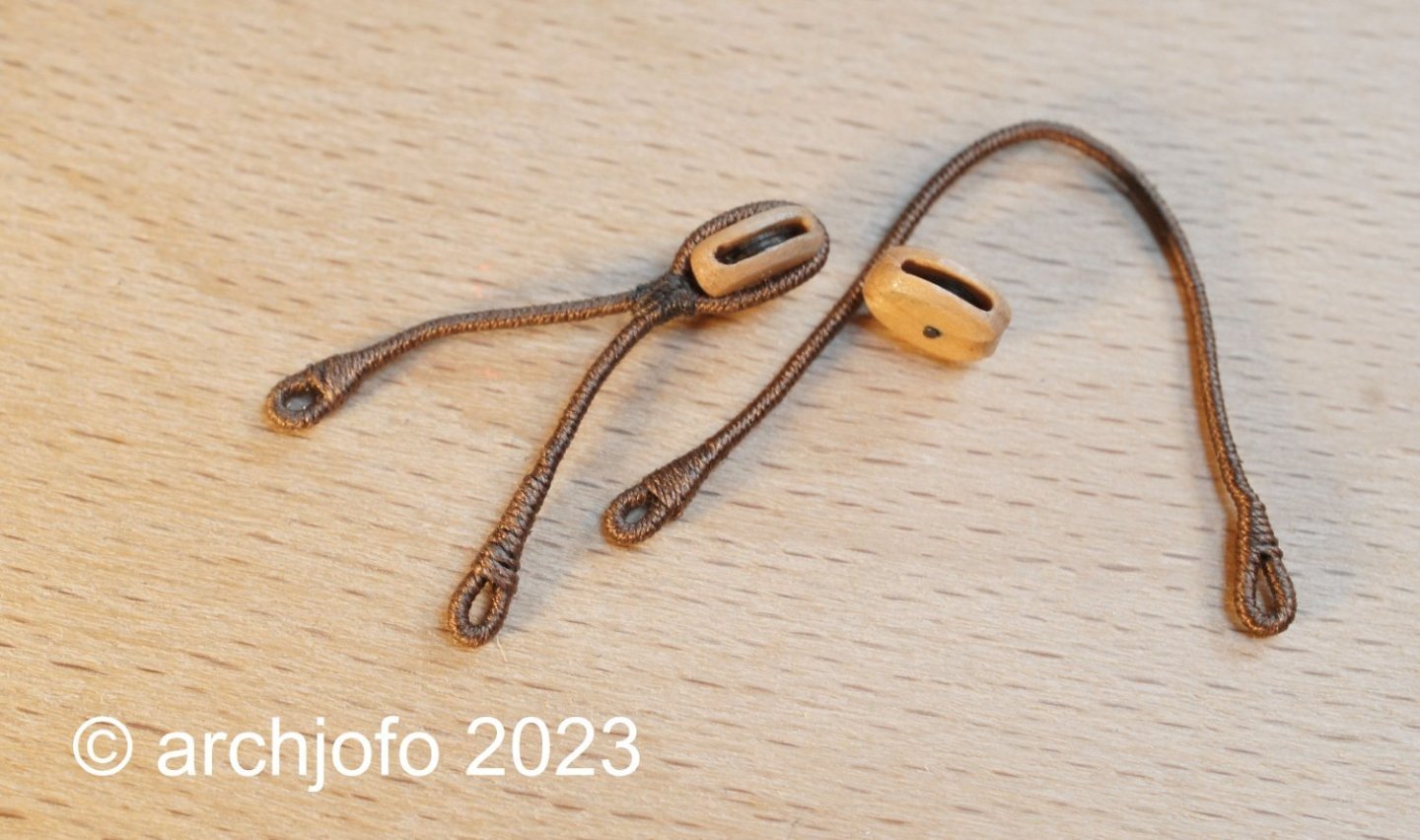
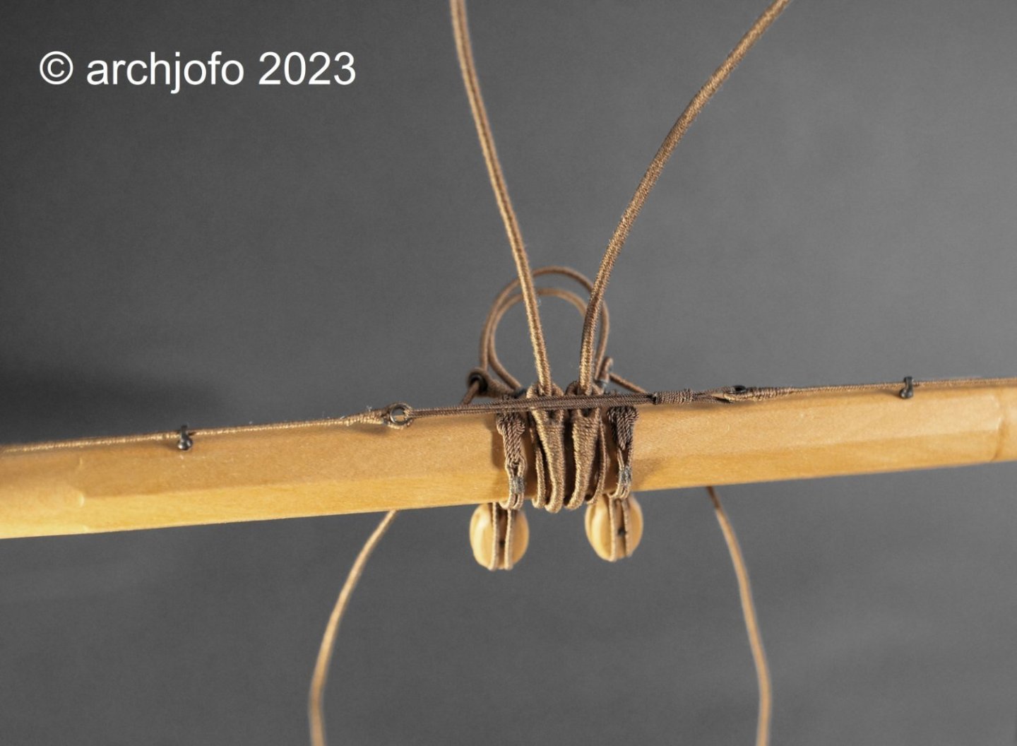
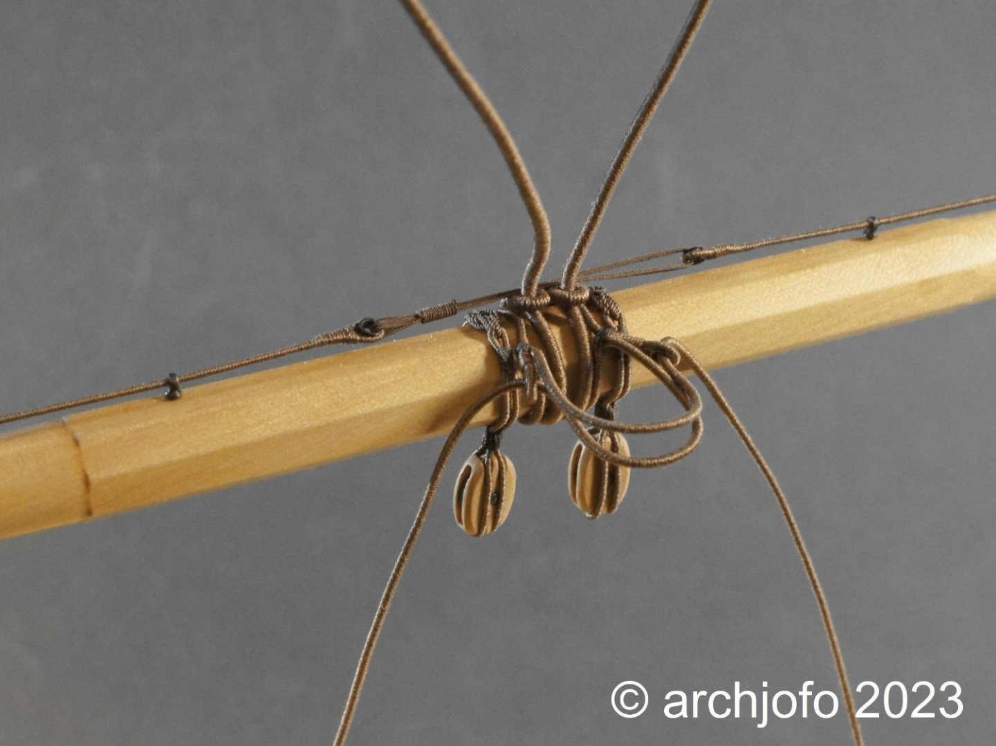
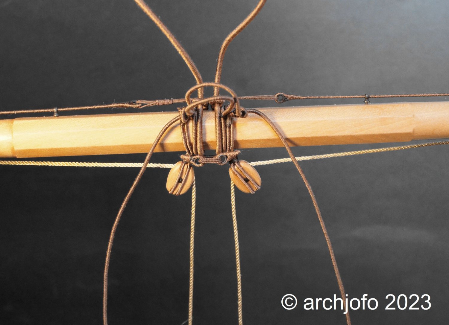
Continuation: Equipment of the fore yard -Truss pendants / Drosse d'une basse vergue As announced, I made the truss pendants for the fore yard. The truss pendants consists of two partly served ropes, at each end of which a thimble was spliced in. In the following picture you can see how one side of the truss pendants is attached to the yard by means of lashing. Later it will be moved to the right position. The next picture shows the finished truss pendants. Admittedly, it looks a bit wild, but I think you can see it so far. In this context, I show an illustration that once again clarifies the functional principle of the truss pendants. Unlike the British, where the ropes went to the deck for mooring, the French led the rope ends upward over sheave gates in the trestle trees to the top. There they were lashed down with tackles. As with the main yard, the position of the two quarter blocks is secured with a strop so as not to be pulled toward the ends of the yards by the sheets. Not to be forgotten is the jackstay of the fore yard, which I will do next. To be continued ...

-
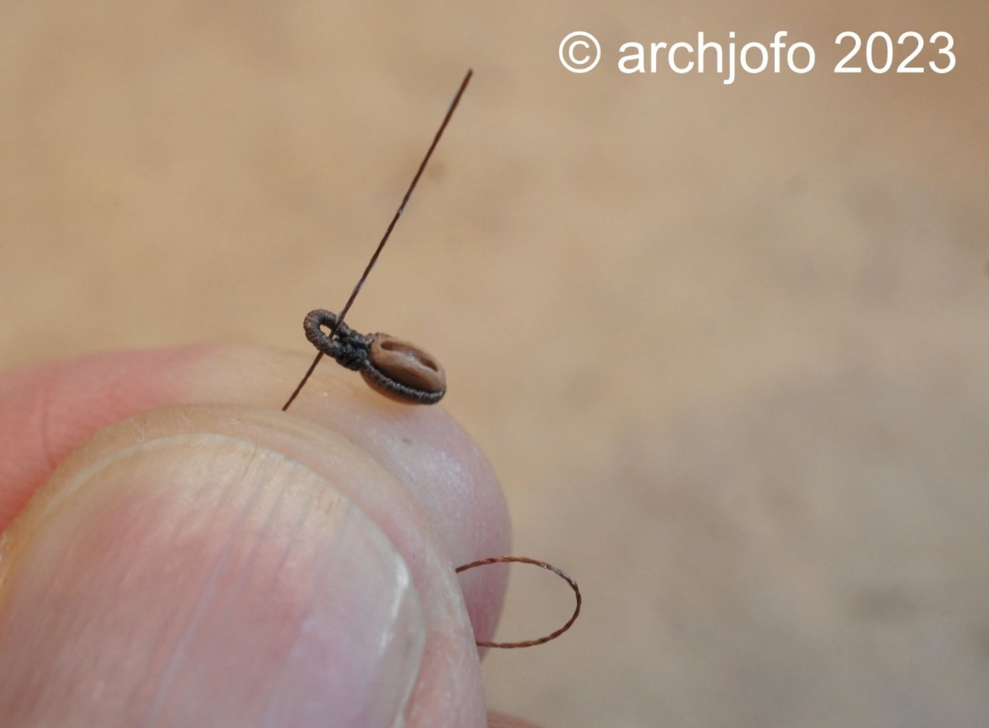
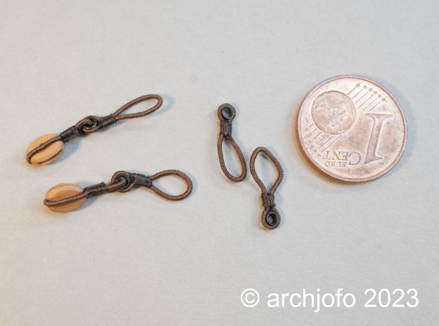
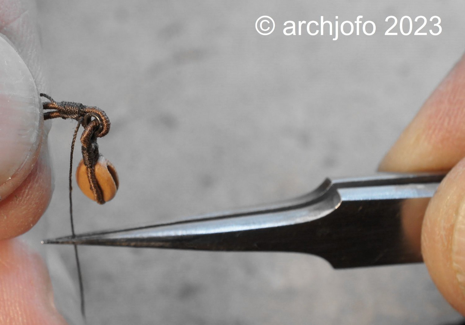
Equipment of the fore yard - Blocks for the sheets and clewline - Poulies d'ecoute et Poulies de cargue de point At the moment I am busy with the equipment of the fore yared. Basically it is the same work as for the main yard, but everything a bit smaller. In order to avoid repetitions of the previous reports, I will try to go into one or the other manufacturing detail in more detail in this section of the work. I tried to determine the length of the strops for the yard blocks with a thin brass wire, as shown below in the example for the sheet blocks. When making the strops, the areas of the eye splices are served first, and then the entire length is served between them. The round seizings, as shown in the following illustration, I try to lay the turns as neatly as possible next to each other, and then use two strokes across to form the finish, as was probably done in the original. Analogous to the Großrah, the blockstrops were then attached to the fore yard at the appropriate positions using rose lashing. In the next step I will prepare the truss pendants with ø 34 mm (in model scale ø 0.70 mm) for the fore yard. To be continued ...


-
Completion: Equipment of the main yard With the fixing of the studding sail booms to the main yard, another small milestone was reached: The main yard is finished with all equipment elements and prepared for mounting on the model, which will be done later. In the next step I will equip the fore yard with the takele elements. I will certainly make faster progress with this, since I have already prepared some equipment parts and many clarifications of execution details have also already been made. To be continued ...


-
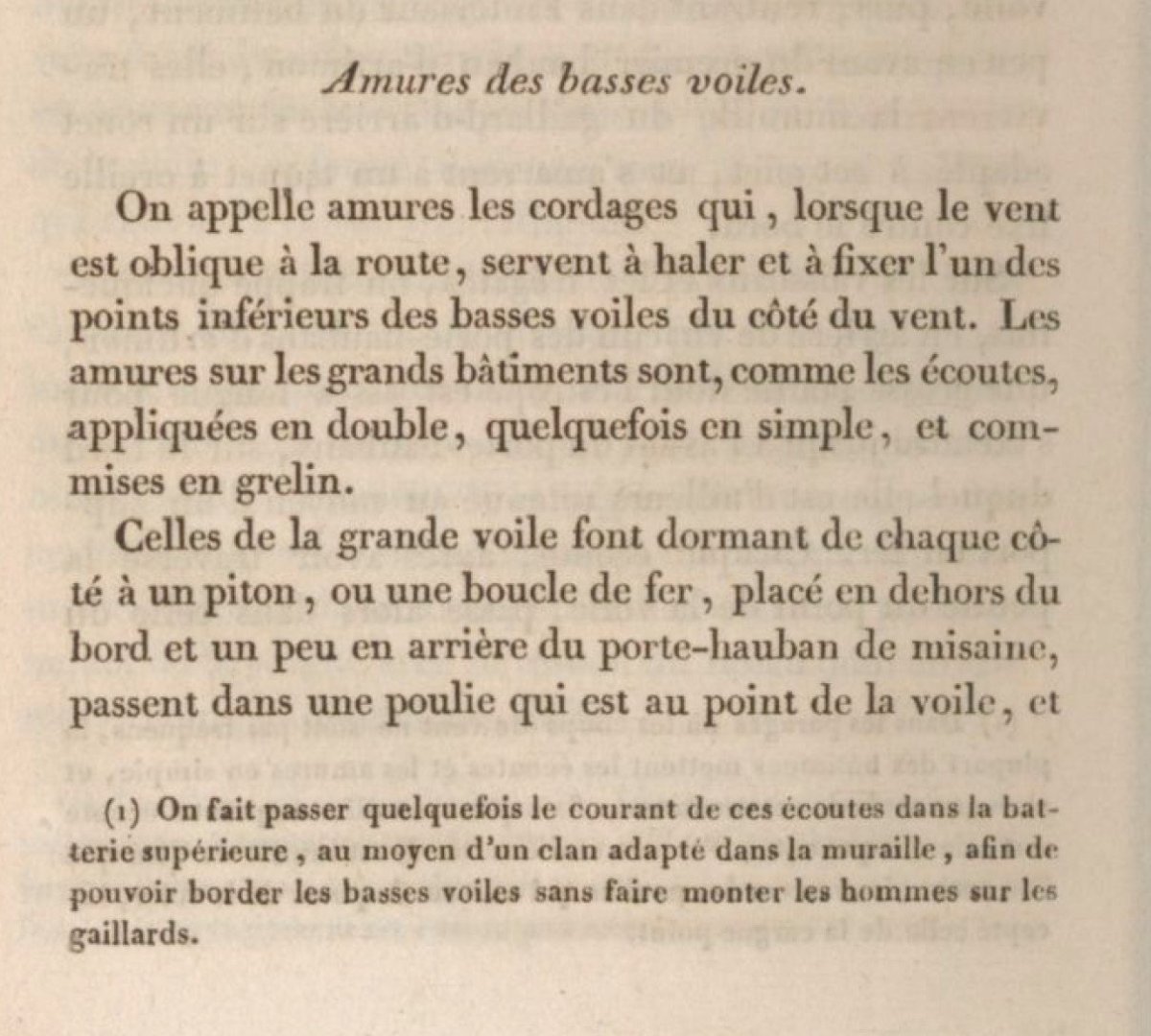
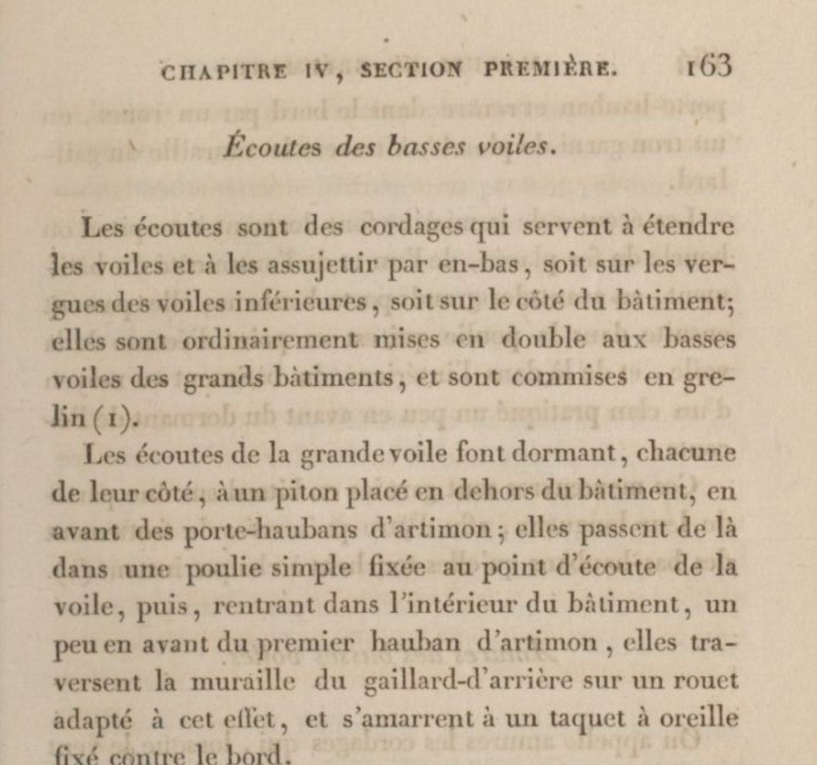
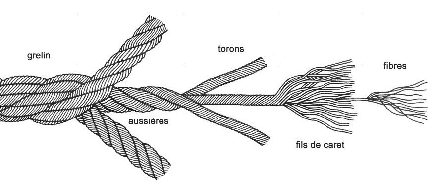
@jdbondy Thank you for your interest and positive response. Continuation: Equipment of the main yard - Tacks and sheets First of all, I would like to thank G. Delacroix for his interesting contribution. In addition to his information, I was able to read the following in a French standard work on the rigging of sailing ships in the 19th century "Manuel de gréement par F.-A. Costé, Paris1829": Thus, in the time of the La Créole, the tacks and sheets of the lower sails were definitely also made of Grelins (cable-laid ropes). In addition, these also served for the standing parts. In any case, a very interesting information, which I will try to implement adequately on my model. Here are the first attempts to make a "Grelin": See you soon ....

-
Hello, cable-laid should be correct. In the meantime I have found a description of the French terms for this type of rope on the Internet:
-
@G. Delacroix Hello, many thanks for the quick response. For better understanding, does cable mean cable-laid?
-
@G. Delacroix @wefalck I am grateful for the interesting clarification on the tarring of cordage and I was happy. So I didn't do much wrong in that regard. Can you say something about the type of cordage for the tacks and sheets for the main and foresail?
-
@jfhealey Thanks for the nice comment. Continuation: Equipment of the main yard - arrangement of the blocks for the clewlines, sheets and tacks - Bouquet de manouvres de grand voile Since I intend to equip the yards with all the necessary rigging elements, I will also prepare the arrangements for the blocks of clewlines, sheets and tacks and pull in the necessary ropes. These elements are not present on the original model in Paris. In the meantime I have made the corresponding single blocks for the main yard including the toggles (no stopper knots). In doing so, I start from double tacks, as they are also provided for in the monograph and became more or less common at the beginning of the 19th century. In this respect, the question of the rejuvenated tacks should have been settled, right? The question remains as to what type of ropes were used. To attach the Clewlines ø 17 mm (ø 0.35 mm on a scale of 1:48) to the yards, so-called timber hitch were most likely used, as shown below. Source: Manuel Du Gabier, 1875 Source: Handbook of Seamanship, Franz Ulffers, 1872 Of course, when rigging a model, everyone inevitably comes to the point where the question arises as to how the block strops of the running rigging should be executed in terms of colour. Either hemp-colored, or brown to black as tarred cordage. I read somewhere that anything that moves doesn't get tarred, and anything that doesn't move gets tarred. This can also be seen on the rigging of the L'Hermione replica, so I use it as a guide for my model. This is how the finished arrangement for the blocks for the clewlines, sheets and tacks looks like: In a hurry, I accidentally made the attachment inside. Of course, this has to be done on the outside towards the yardarm and is still being changed. Sequel follows …


-
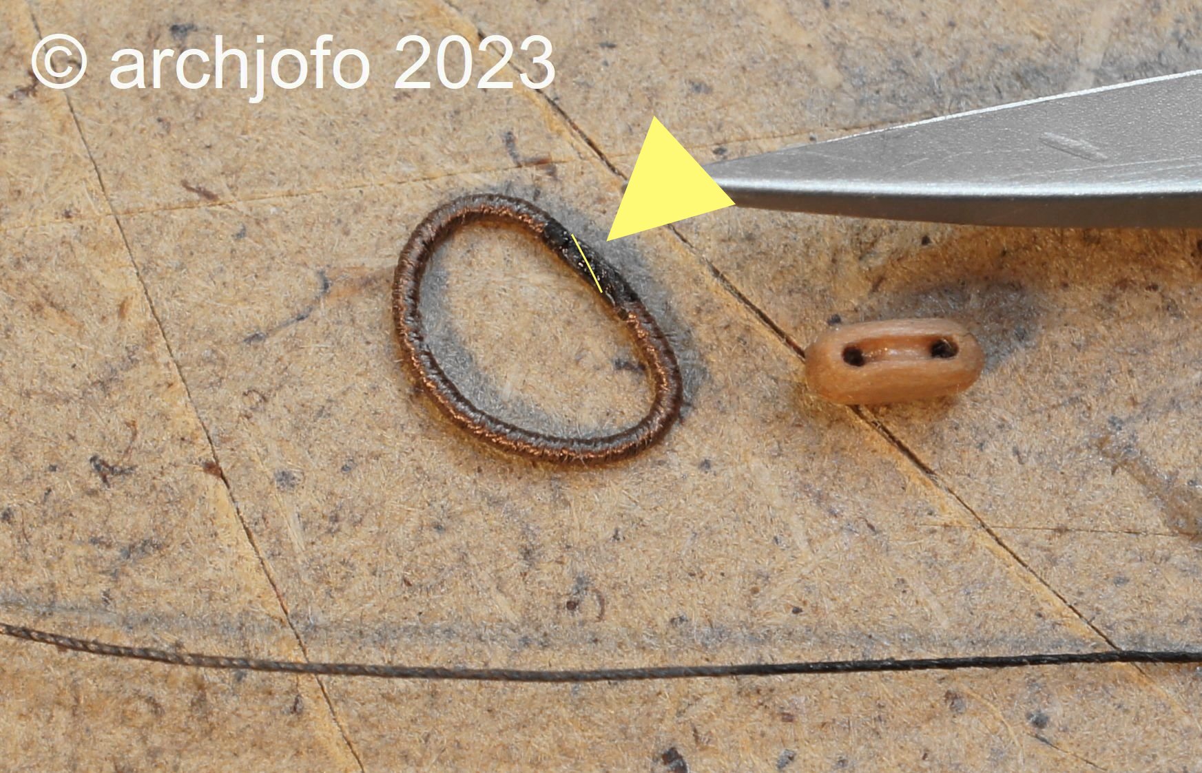
@bdgiantman2 Hello Brian, the ropes are made of silk. The two ends were glued with superglue at the point marked in yellow. In order to create the largest possible contact surface for the glue, I cut off the two ends at an angle with a scalpel. Thank you for the interest.

-
@giampieroricci Hello, getting such great praise from such an excellent model builder is also something very special. Thank you very much for that. I would also like to thank all the others for the many LIKES.
-
@Gahm @jdbondy Thank you for your interest and the kind words. Also many thanks to all the others for the LIKES. Continued: Equipment of the main yard - Blocks for buntlines and clewlines - Poulies de cargue fond et poulies de bouline In the meantime I have made 12 blocks l = 3.4 mm for the blocks for buntlines and clewlines of the lower yards. I tried to make the seizing as small as possible, which wasn't easy with this size. These blocks were moored to jackstay as shown in the following images. I will make my model of the La Créole without the sails, as I have already mentioned several times, analogous to the Paris model. Nevertheless, I would like to attach the arrangement for the clews of the lower sails. These rigging elements are not shown on the original model, so the sheets, tacks and clewlines with the necessary blocks are missing. At the moment I'm still researching whether single or double tacks were used at La Créole. It still needs to be clarified how the fore tacks were led to the mooring cleats, as there is no information on this in the monograph. There is also another question, whether the French also use cable-laid ropes for the tack ropes? Up soon …


-
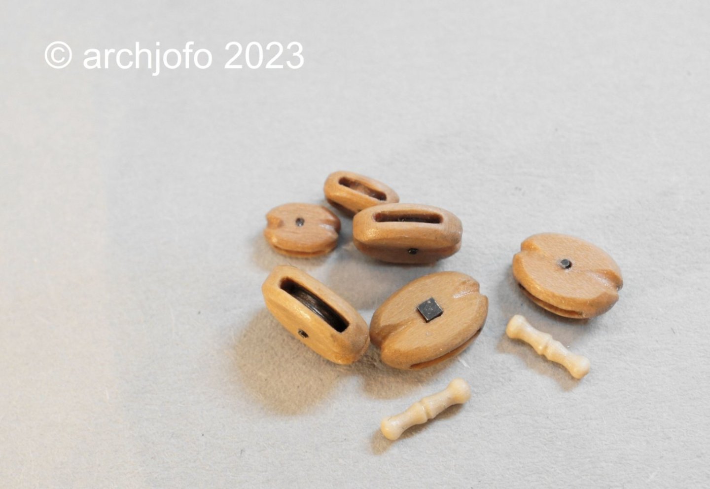
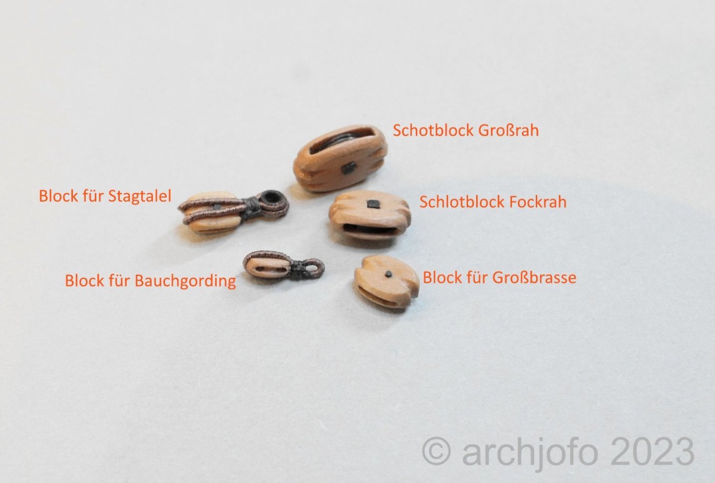
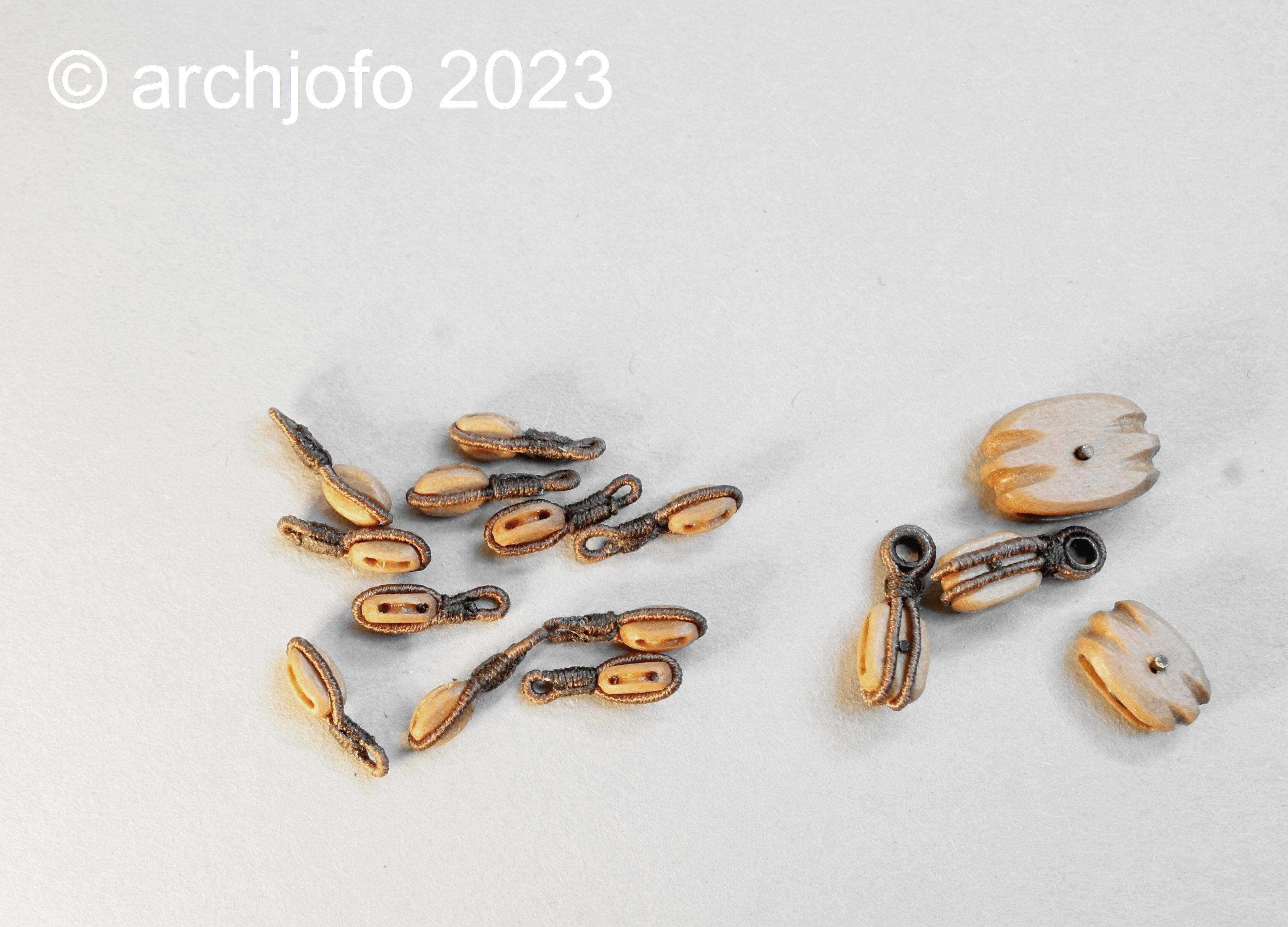
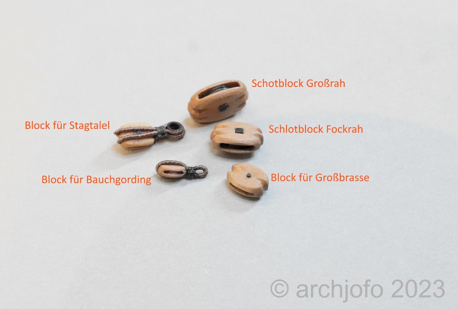
@BobG Hi Bob, Thanks for the positive affirmation. I would also like to thank you for the many LIKES. Continued: Equipment of the big yard - Blocks for buntlines and clewlines - Poulies de cargue fond et poulies de bouline According to the relevant table in the monograph, the blocks for the buntlines and clewlines are only 3.4 mm long and 1.3 mm thick at a scale of 1:48. With this block size, the sheaves with a thickness of d= 0.5 mm are not used separately, but worked out. In total I need 12 blocks for the main yard and fore yard. Before I start "series production", I made a "prototype" in the usual way and equipped it with a served strop. The eye is used to attach to the jackstay. In the following image I have shown different block types and sizes compared to a block for a buntlines. The next picture shows how these blocks are attached to the jackstay by means of tying. Sequel follows …

-
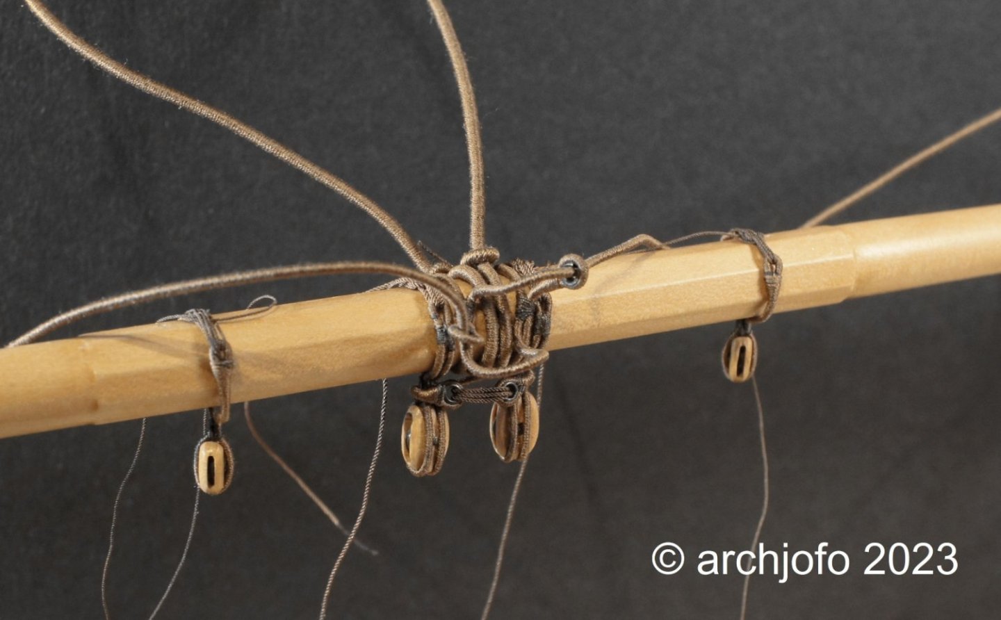
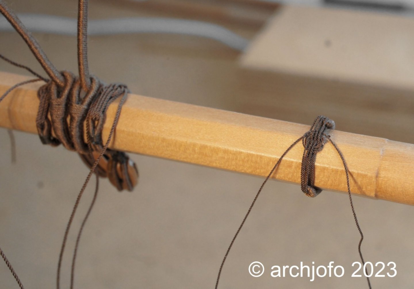
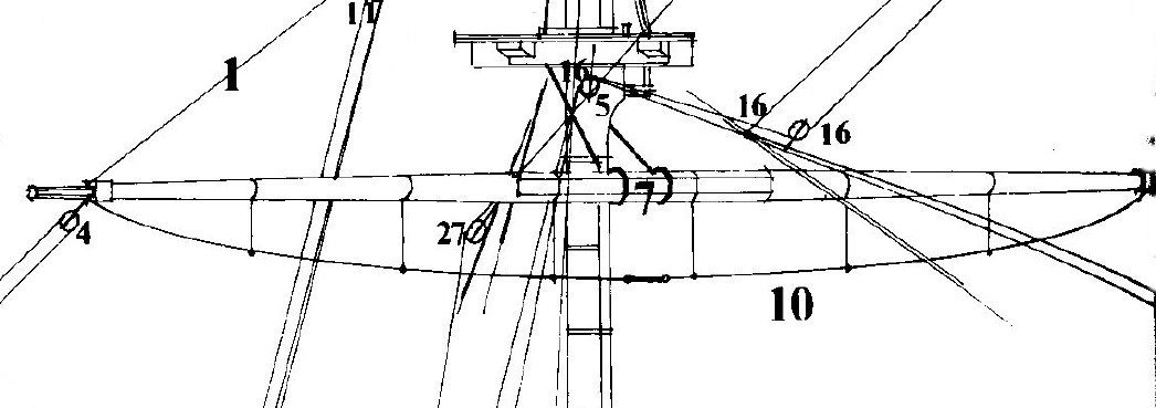
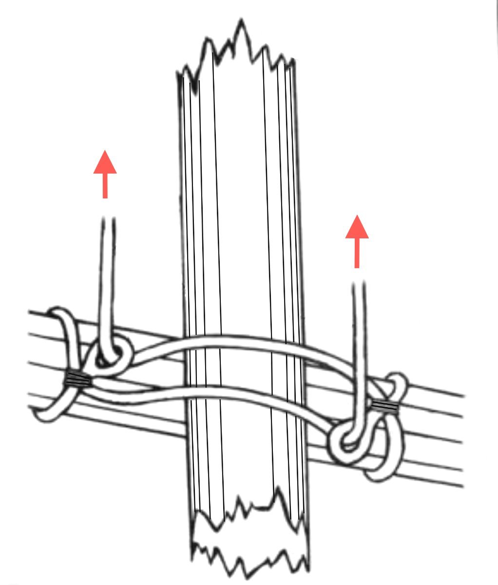
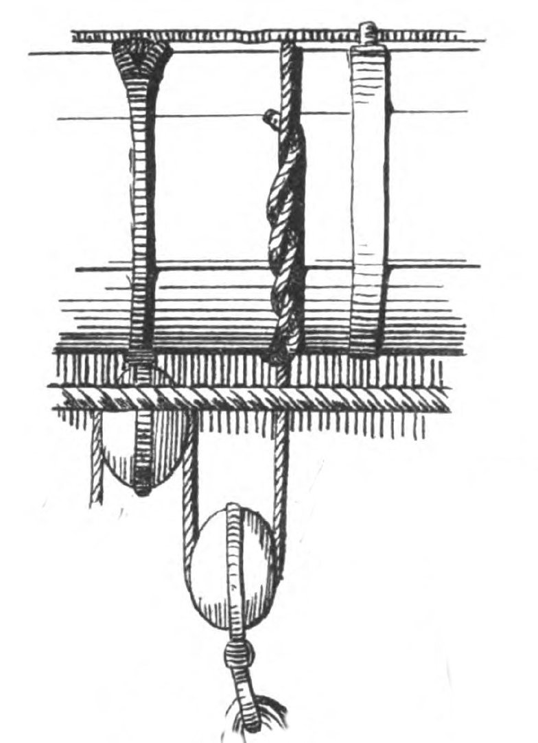
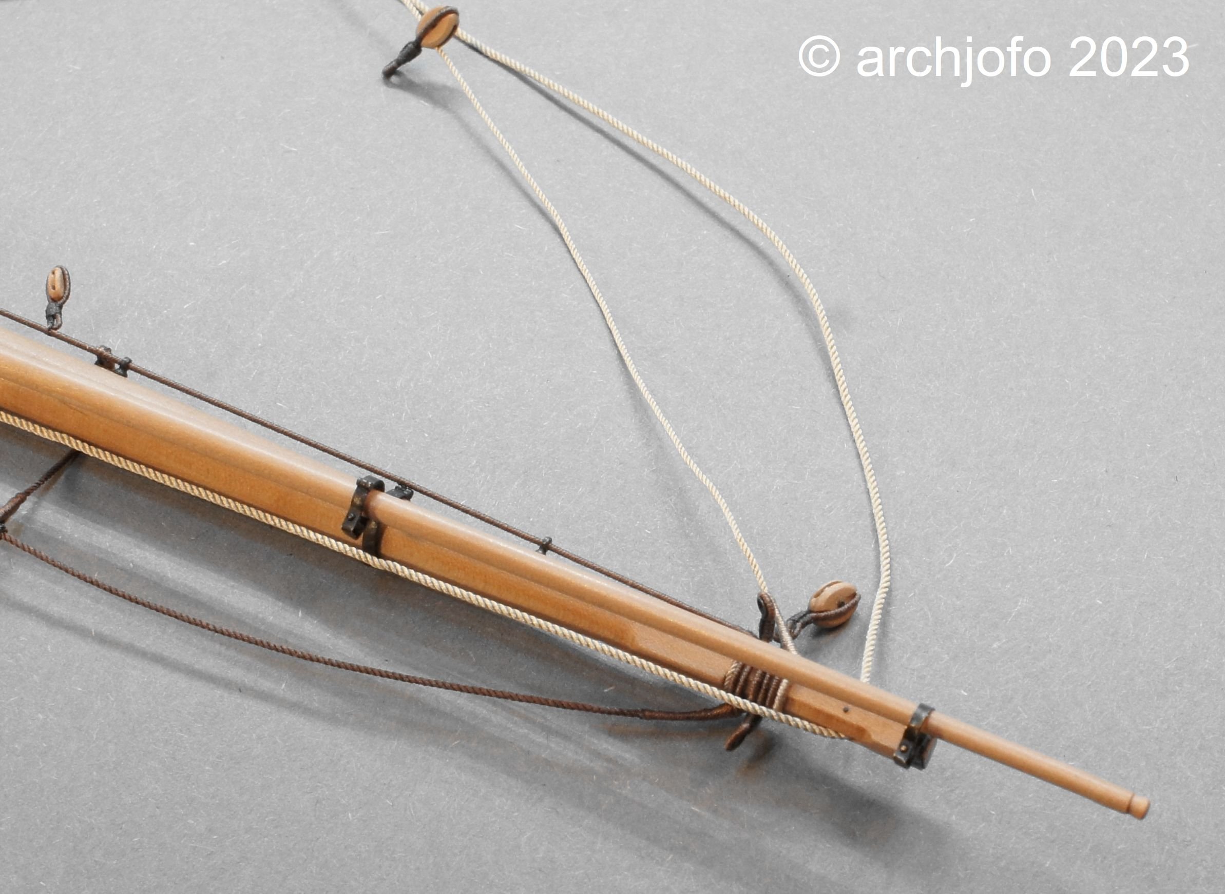
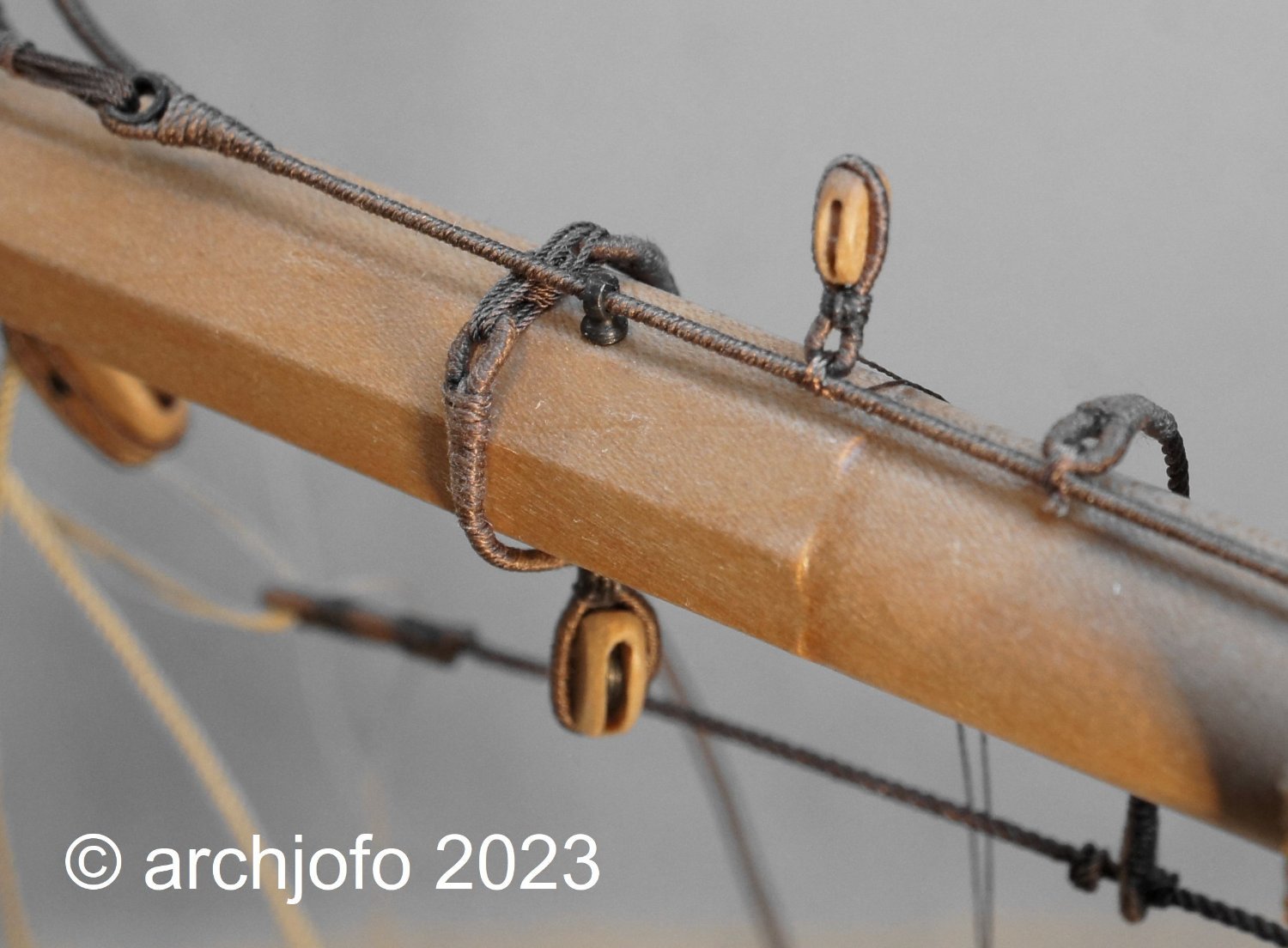
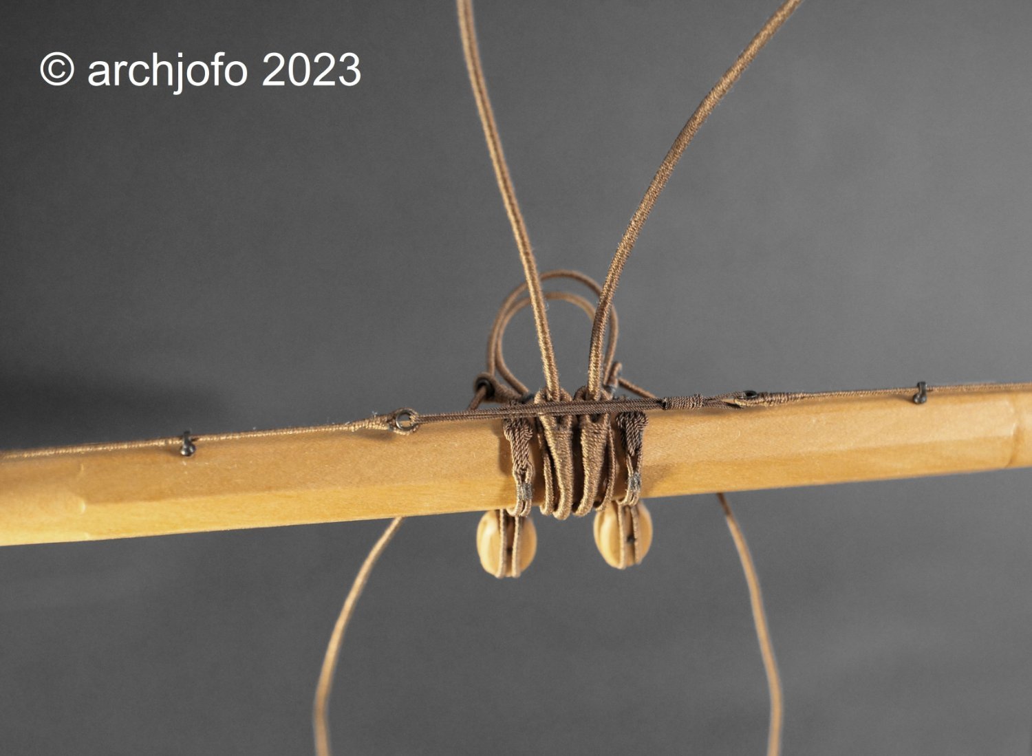
@Nunnehi (Don) Hello, Thank you for your positive comment. I would like to thank the others for the LIKES. Continued: Main yard equipment and others - Footropes and stirrups - Marchepieds et étriers - etc. The blocks for the La Créole's braces were attached directly to the yard arms by strop. The connection of the blocks for the braces with the thimble sling was called "Dog and Bitch". In addition to the strops for the braces, strops for the yard tackles also had to be considered, as can be seen in the following picture. The yard tackles were then only attached when needed. In connection with the stay tackles, e.g. B. the boats are loaded and unloaded. The next picture shows the main yard with the newly installed rigging elements. For the lower yards, this corvette had simple yard lifts with a diameter of 30 mm, which went over blocks hooked into the tops for belaying on deck. The yard arms are now fully occupied. The footropes and stirrups that have already been attached still have to be properly lashed down in the middle of the frame. I still have to clarify in detail to what extent these lanyards can still be lashed over the sling of the lower yard, as shown in the following drawing by Nares. Unfortunately I don't have a meaningful picture of the original model. Source: Traité de manoeuvre et de matelotage, George S. Nares, 1868 The attachment of a stirrup to the jackstay can be seen in the next detailed pictures. Finally a picture of the middle of the yard. Except for the blocks for the clewlines and buntlines and the professional attachment of the stunsail booms, the main yard should then be fully equipped. I would not have thought that so many rigging elements would have to be attached to a yard. I learned a lot from the research I did on the internet and relevant specialist literature. In the lower yards that follow, the production of the equipment should be all the faster. For the topsail, topgallant and royal yards, on the other hand, some detailed information is required that still needs to be obtained. Sequel follows …

-
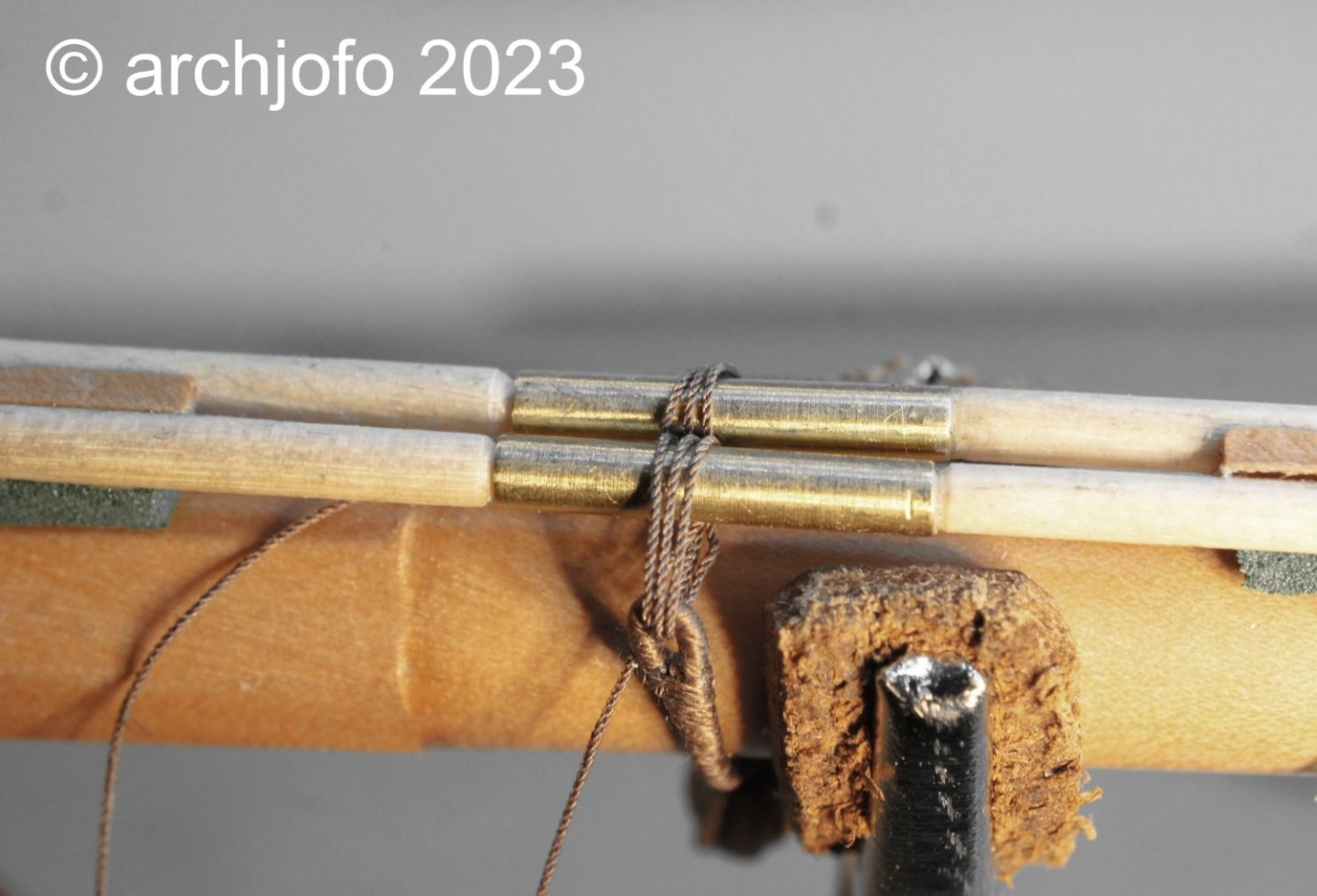
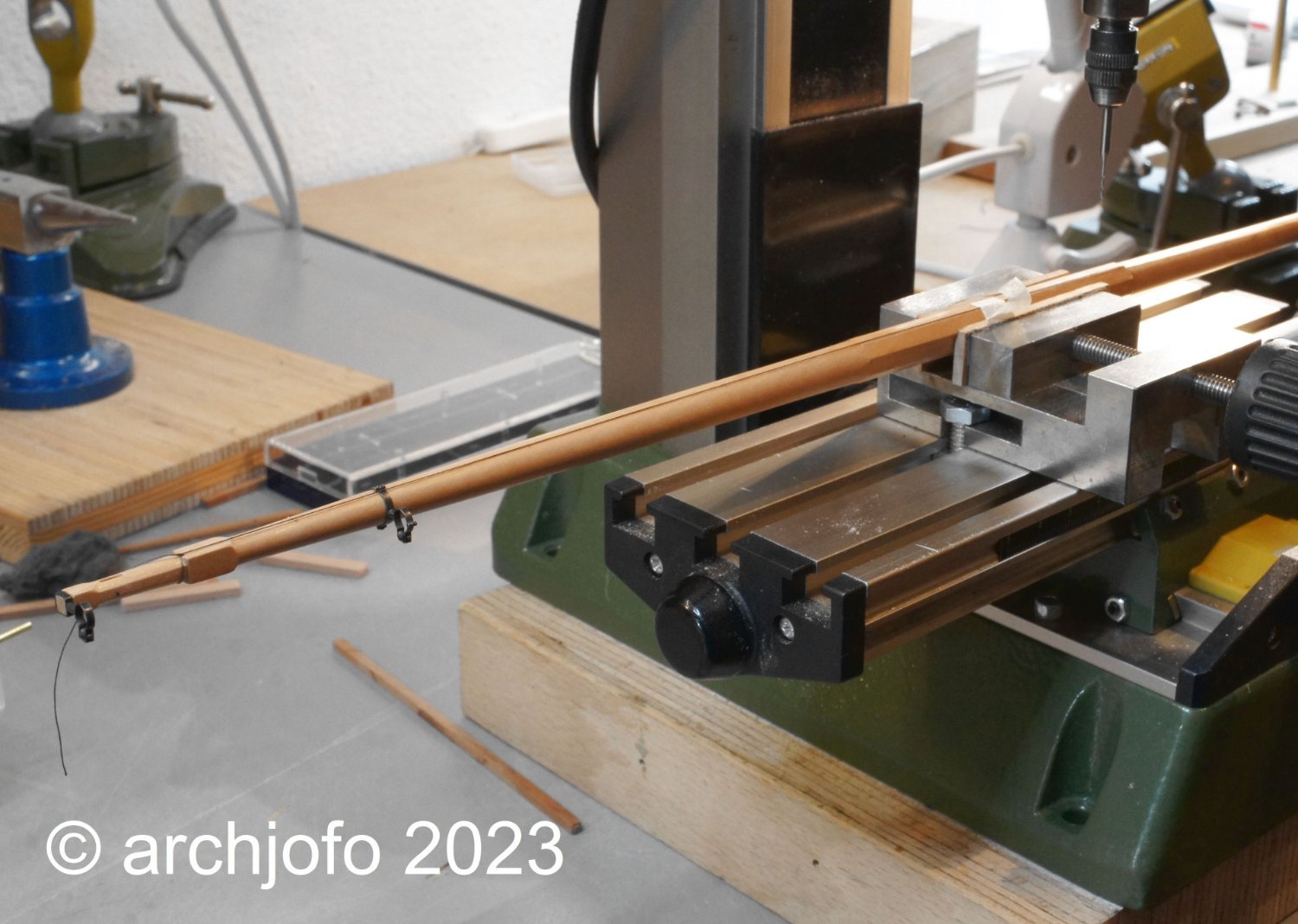
@Mic_Nao @druxey Thank you very much for the nice comments. Thanks also to everyone else for the LIKES. Continued: Equipment of the lower yards - footropes and stirrups - Marchepieds et étriers The arrangement of the footropes on the yards should be given as realistic an appearance as possible. In this respect, it is desirable to bring the stirrups vertically downwards and to let the drawn-through ropes of the footropes sag in their natural form. In order to achieve this on a model scale, of course, a little help has to be given. When making the yards, I initially made the main yard with incorrect yardarms. With this leftover yard I have already carried out tests on the arrangement for the jackstay. Now it serves me once more for experiments regarding the footropes. In this respect, I made provisional footropes and stirrups and installed them at the test yard. After the ropes, which have been coated with diluted white glue, have dried and draped accordingly, the footropes look like the following picture: In the right area of the yard it does not seem to be quite optimal and overall the sag is too big in my opinion, but I think that with this method I can achieve a good result for the model. Soon...

-
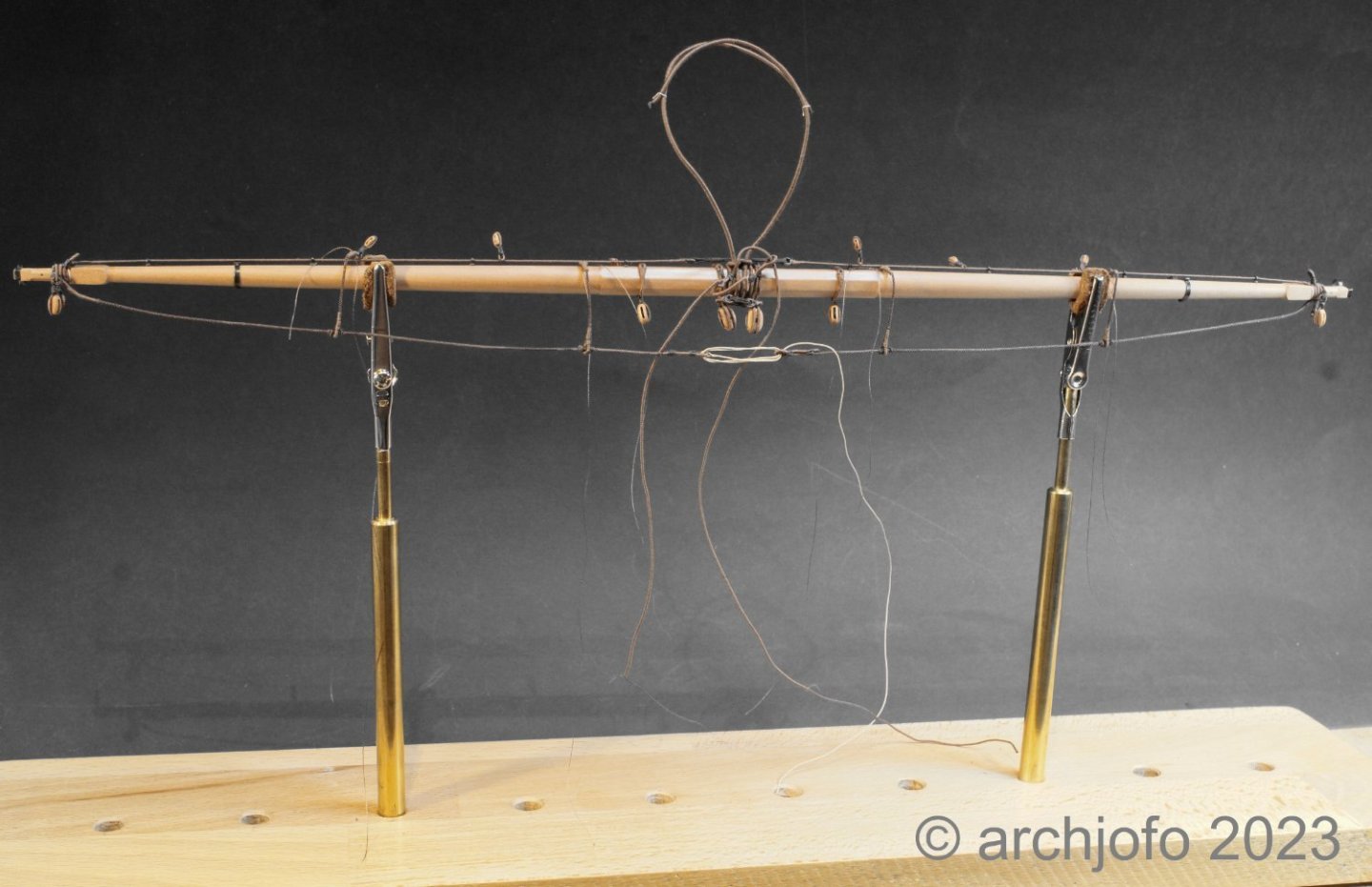
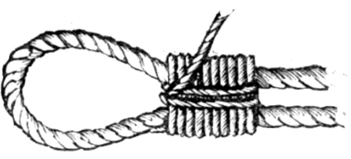
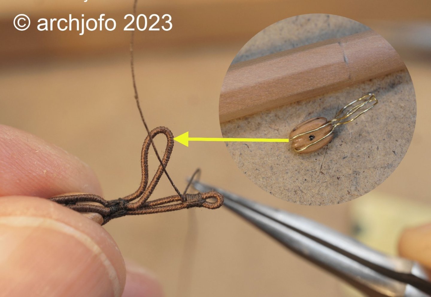
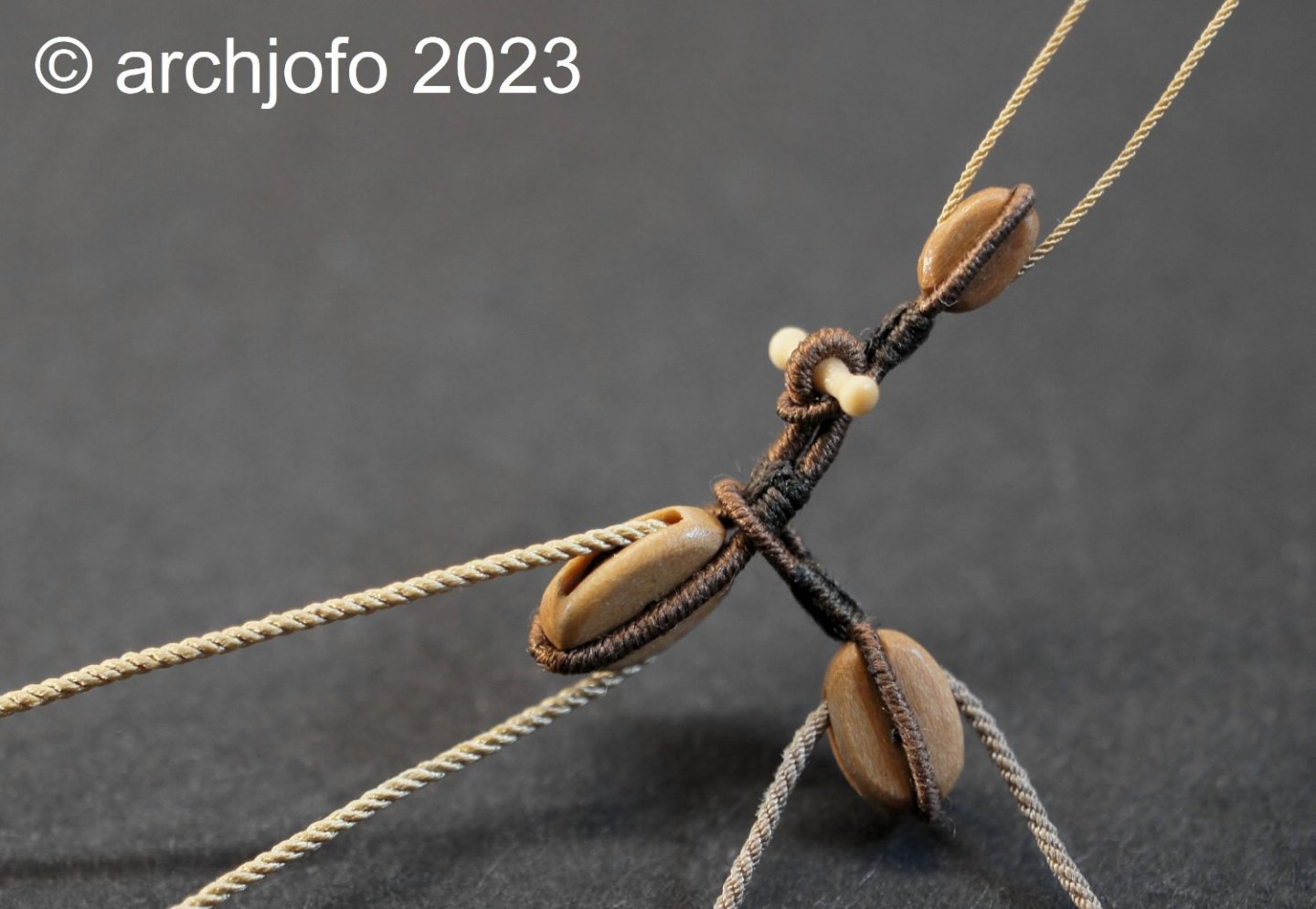
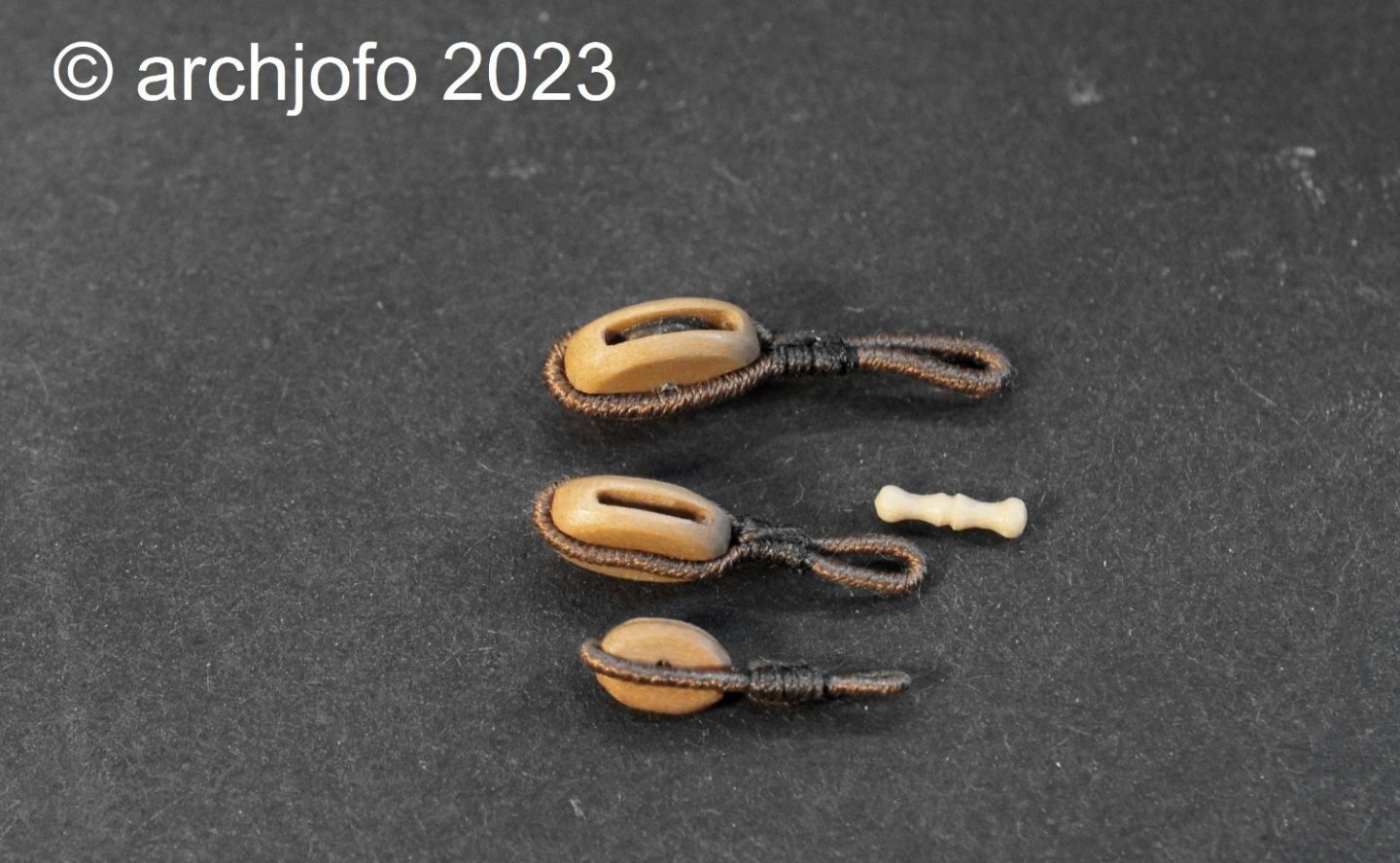
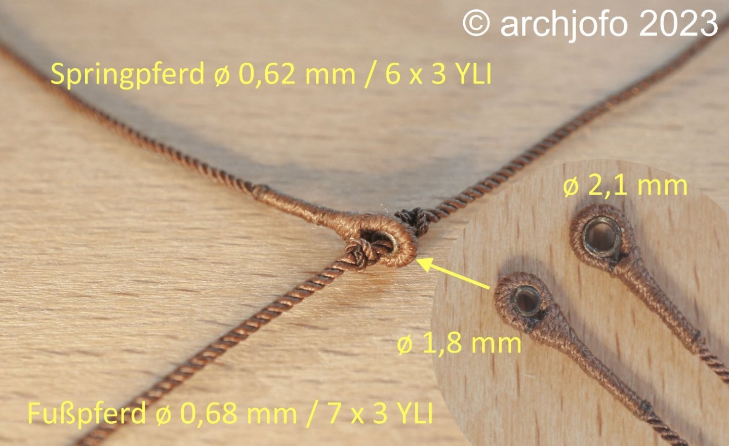
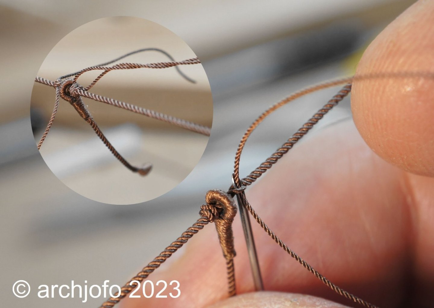
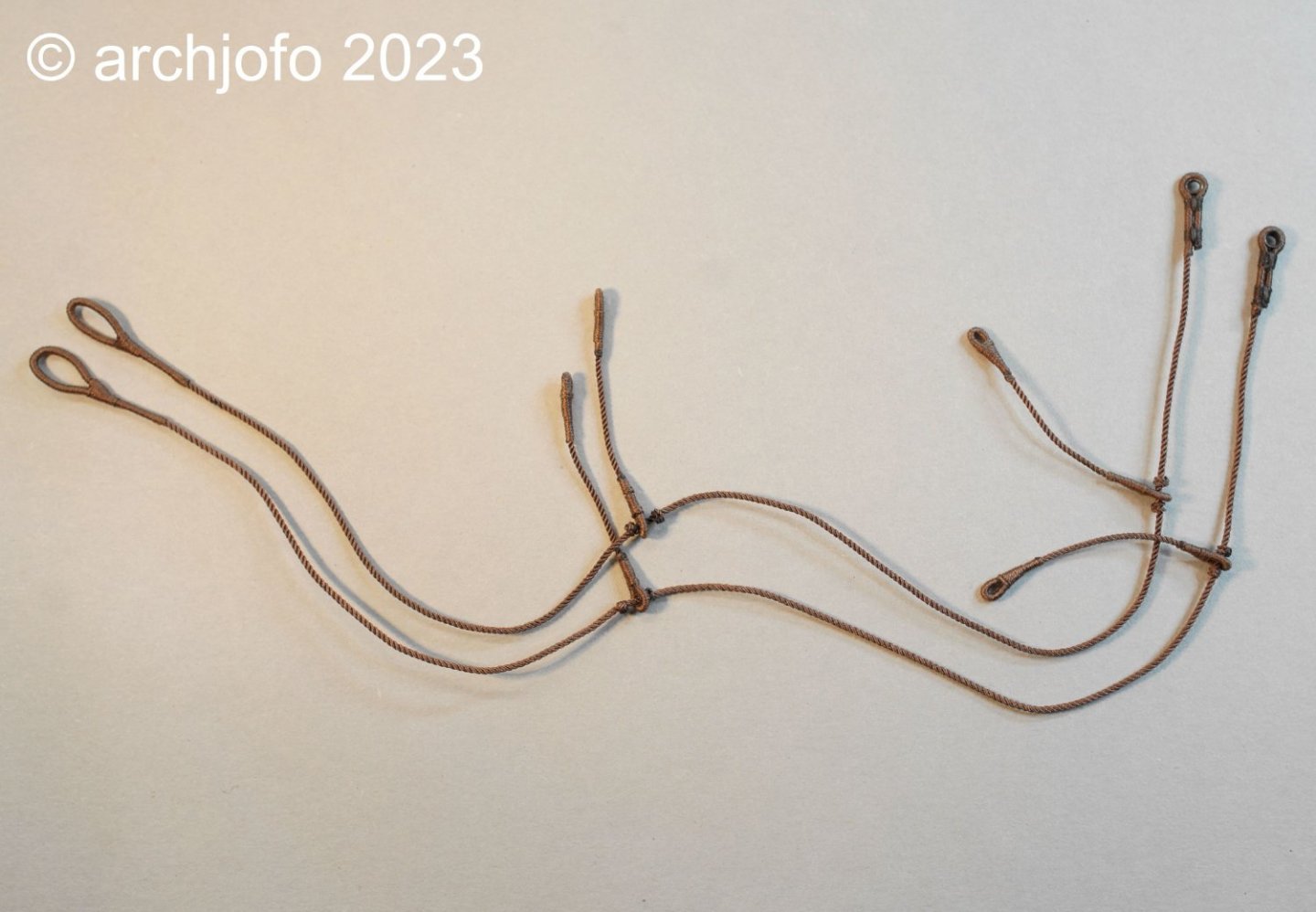
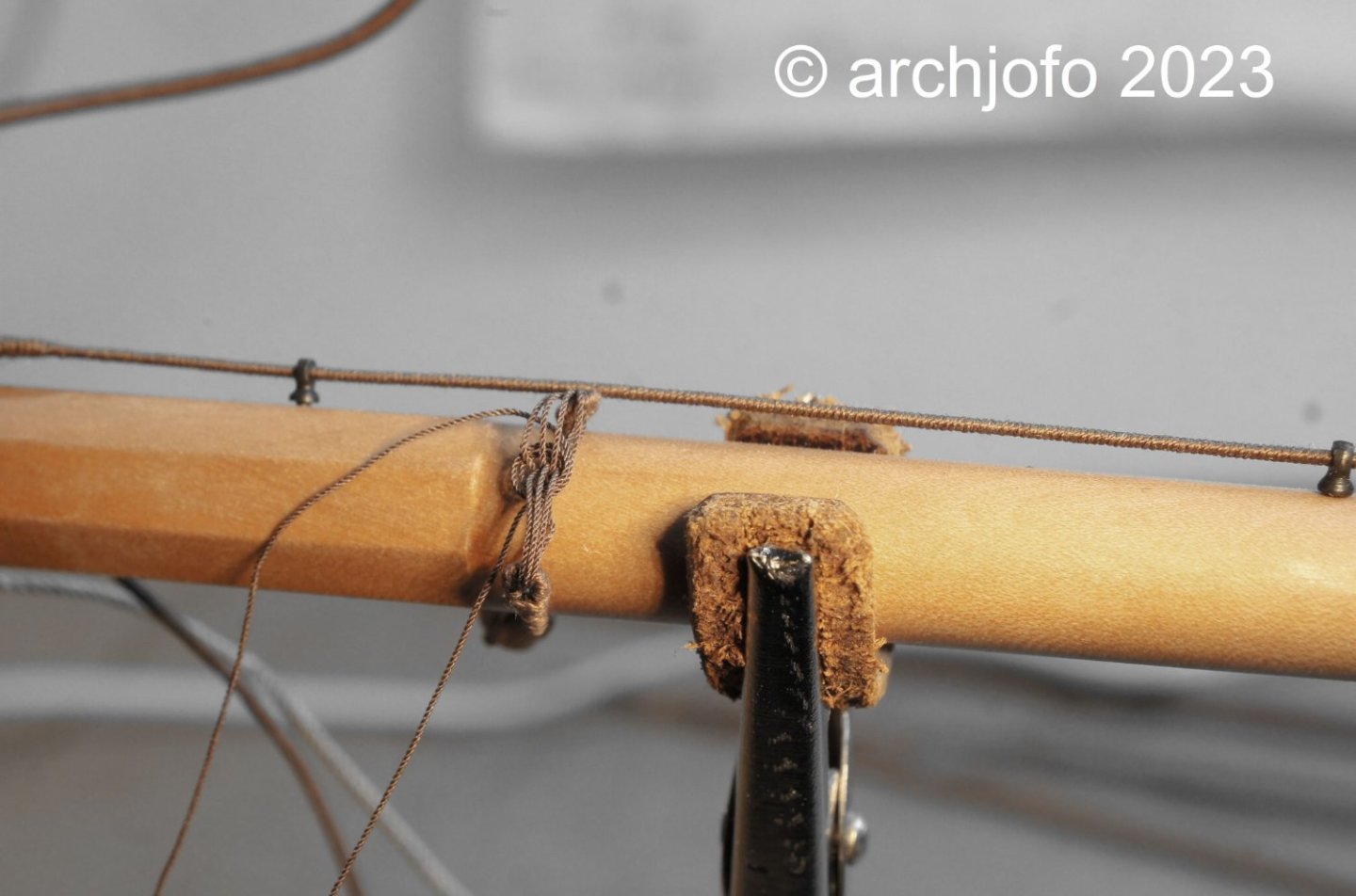
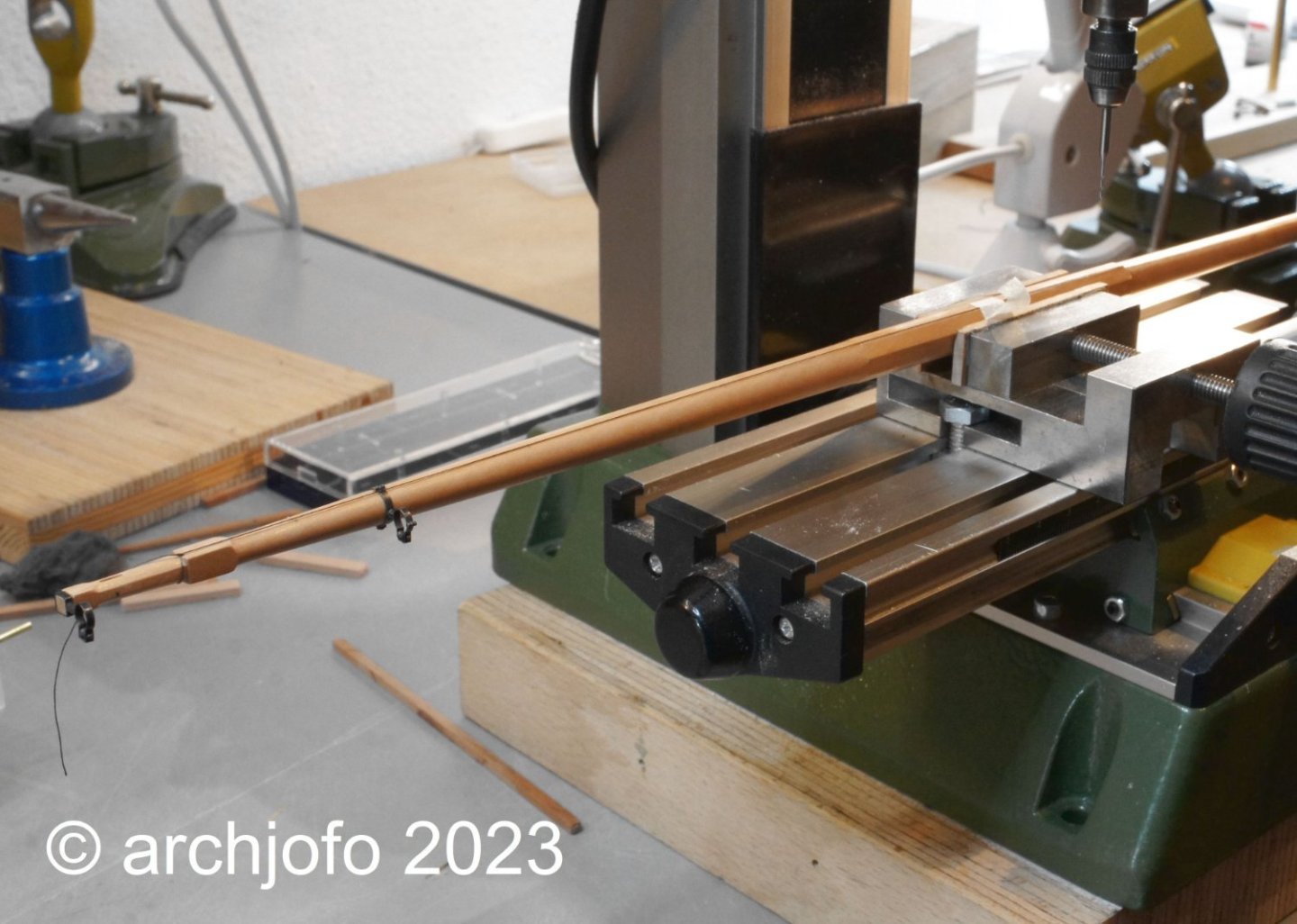
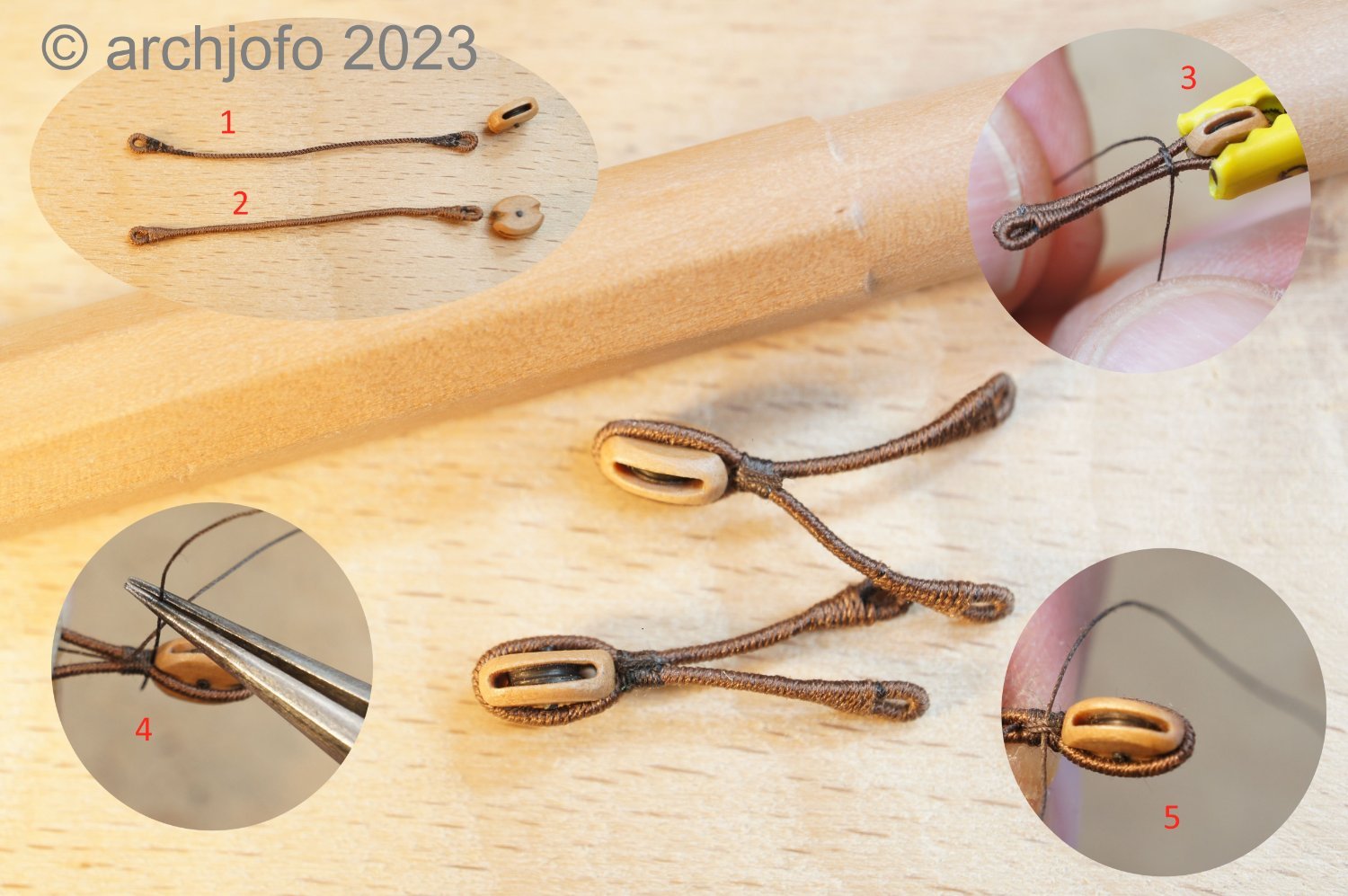
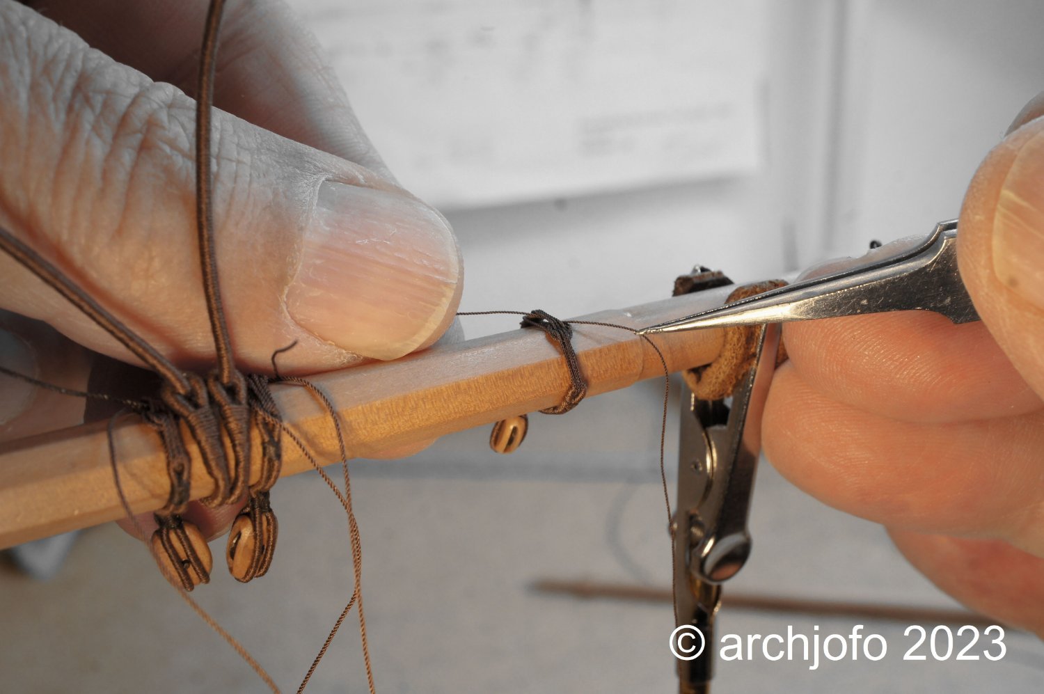
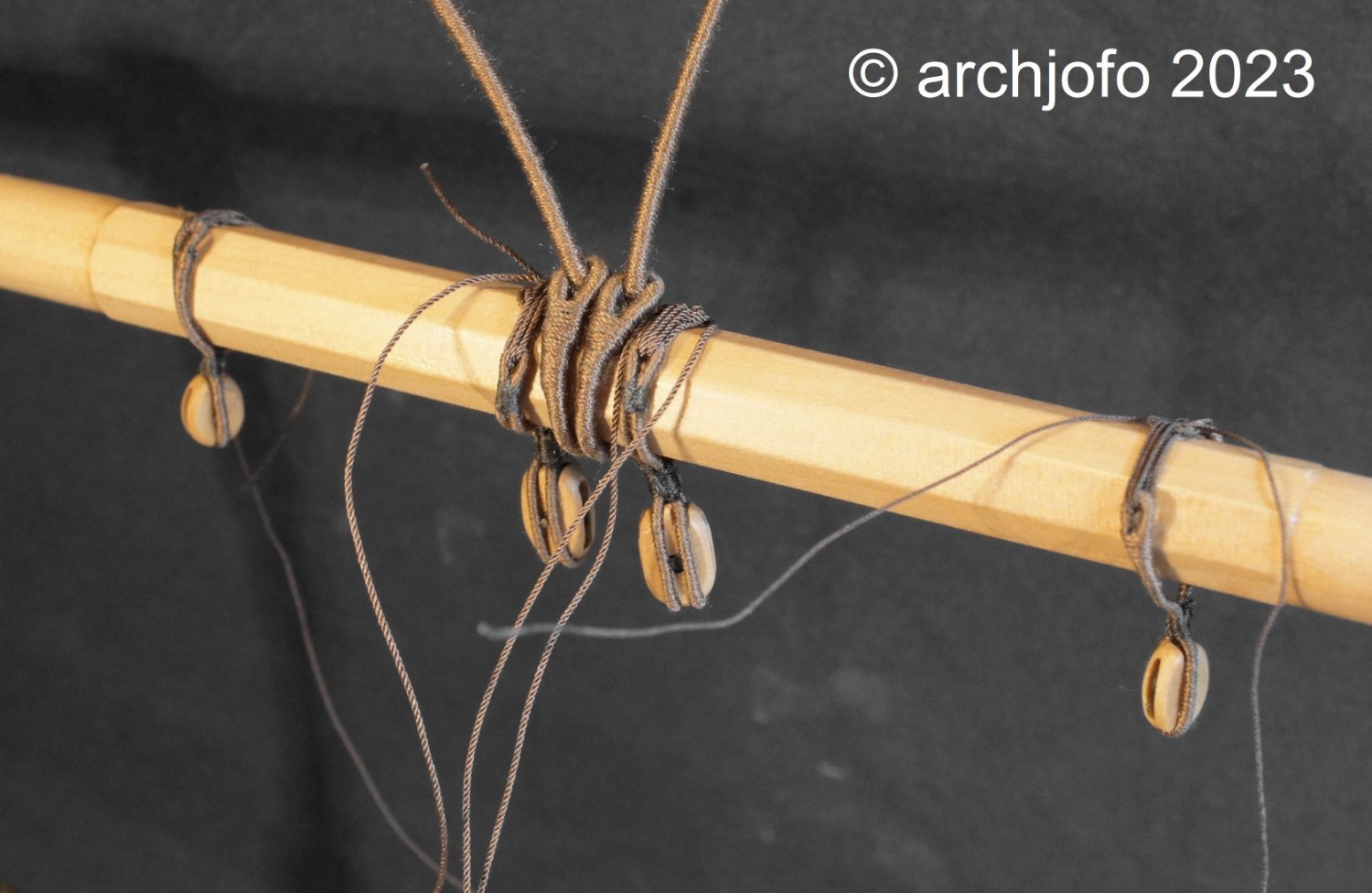
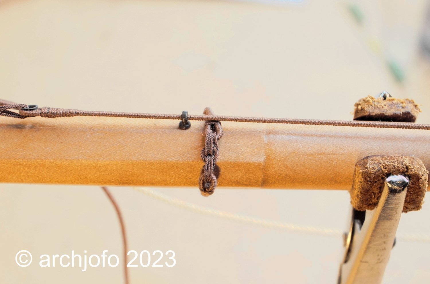
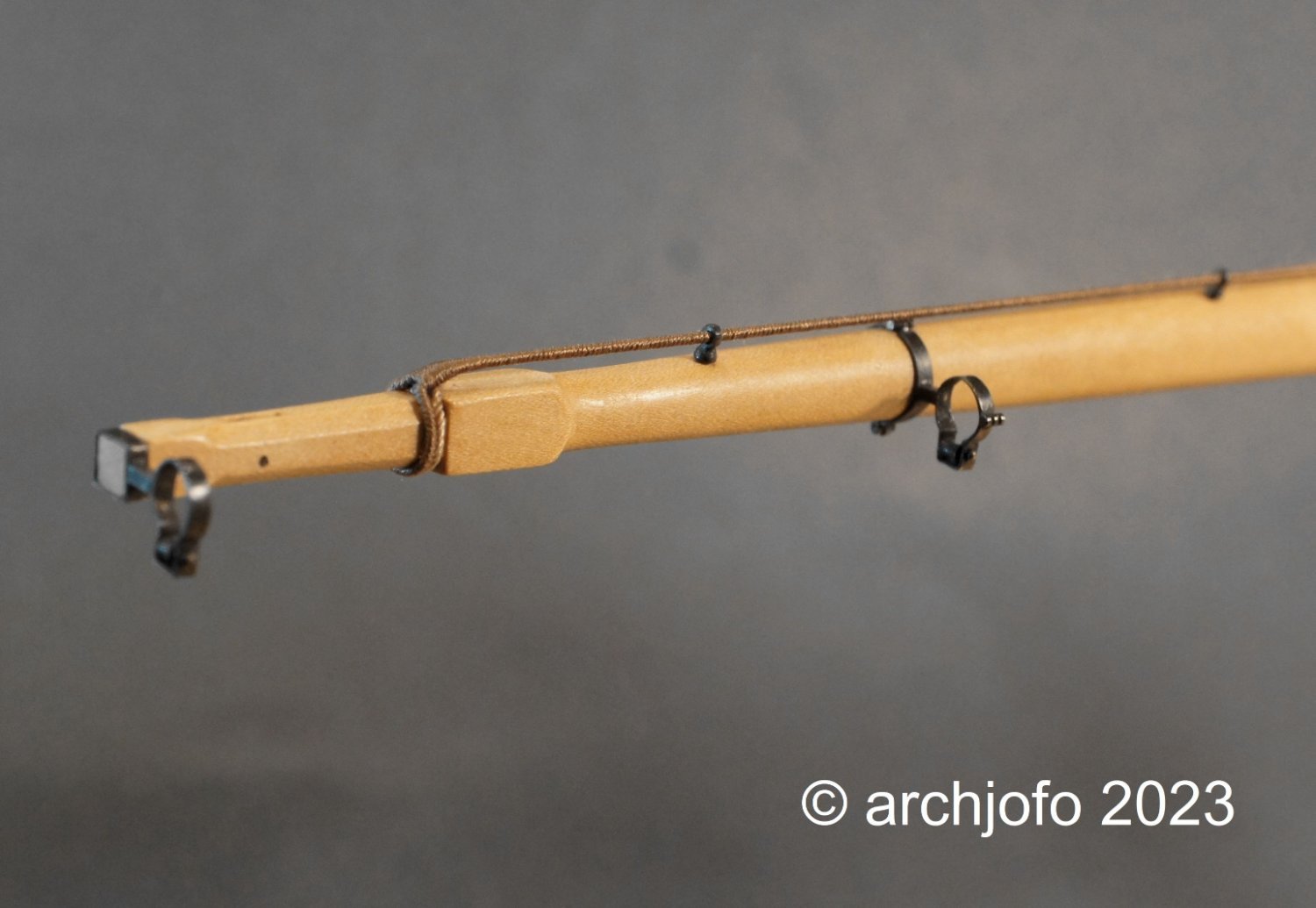
Thanks for the LIKES, I'm very glad you like it. Continuation: Equipment of the lower yards - footropes and stirrups - Marchepieds et étriers In the meantime the ordered brass tubes with various diameters arrived. In this respect, I found out that matching thimbles with ø1.8 mm for the jumpers can be made from brass tubes with ø1.1 mm. The stopper knots presented another challenge. To prevent the footropes from being pulled through the thimbles, for example, so-called "Turk's head knots" were woven in. How are these knots to be depicted reasonably realistically in 1:48 scale? Simple overhand knots do not look very good. After a number of attempts, I found a solution that looks reasonably acceptable in my eyes, as shown in the following picture. On the next picture the footropes and stirrups are ready for the next step. The stopper knots were now placed in the appropriate places as described before, and the stirrups were pulled in between. The original footrope was actually covered with leather between the stopper knots to prevent shame. Four stirrups were sufficient for the lower beam lengths of a corvette. Before I attach the footropes to the yard, I consider how to achieve the most realistic hang. From the top of the yard to the footrope a distance of about 1.05 - 1.10 m should be chosen. This way, the sailors could support themselves well with their feet and work hanging belly-down over the yard. To be continued ...


-
@Keith Black Hello, thank you for the praise. I would also like to thank the others for the many LIKES. With new motivation we continue with "little things": Continued: Equipment of the lower yards - Clew garnet blocks of the main yard - Poulies de cargue de point In the meantime I also lashed the second clew garnet block to the main yard until I can continue with the footropes. Adapted to the slings of the clew garnet blocks, the lashing lines had to be made much thinner than those of the quarter blocks. But even with this, the rose lashings managed tolerably well. Sequel follows …. PS: What is the correct name for these blocks? Clew line block or clew garnet block?

-
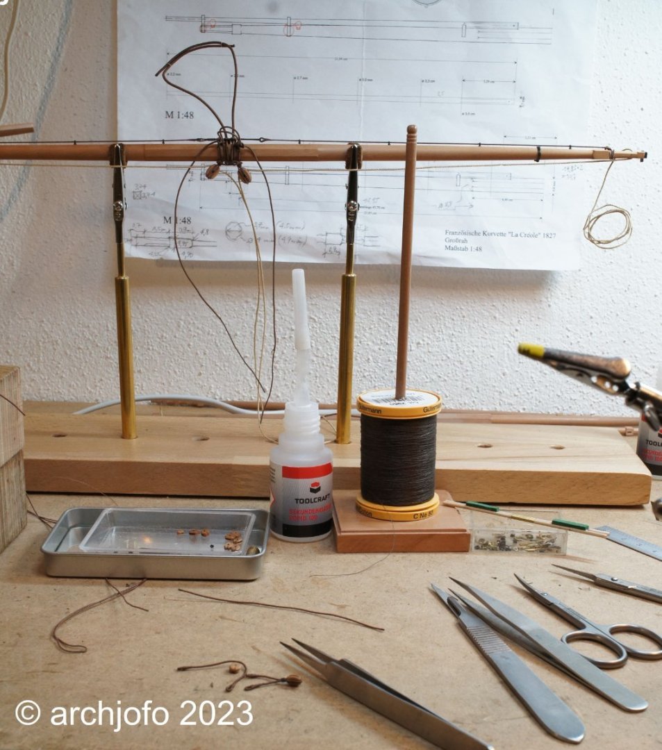
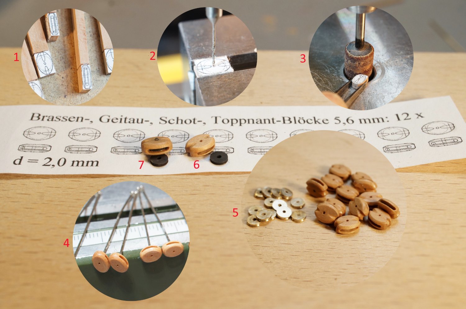
@Dziadeczek @noel_colledge Hello, thank you for the lovely comments. Continued: Equipment of the lower yards - more blocks - poulies As already described, I preferred to produce more blocks for the lower yards. These are blocks for the braces, clew lines and lifts of the main and fore yard and for the sheets of the mizzen yard. A total of 12 pieces with a length of 5.6 mm had to be made. The brass sheaves of the single blocks have a diameter of around 3.2 mm and are 0.6 mm thick. For the clew line blocks (Poulies de cargue de point - the main yard) I have already made the strops as you can see in the next picture. Here's a look at the workspace: Finally a picture from the middle of the main yard with a clew line block that has been lashed down in the meantime. Here, too, a rose lashing was used, which was not easy to accomplish with the necessarily somewhat thinner rigging yarn. The brass tubes have now been delivered. So I can continue with the thimbles for the foot ropes. I hope that the size will be appropriate. Up soon …

-
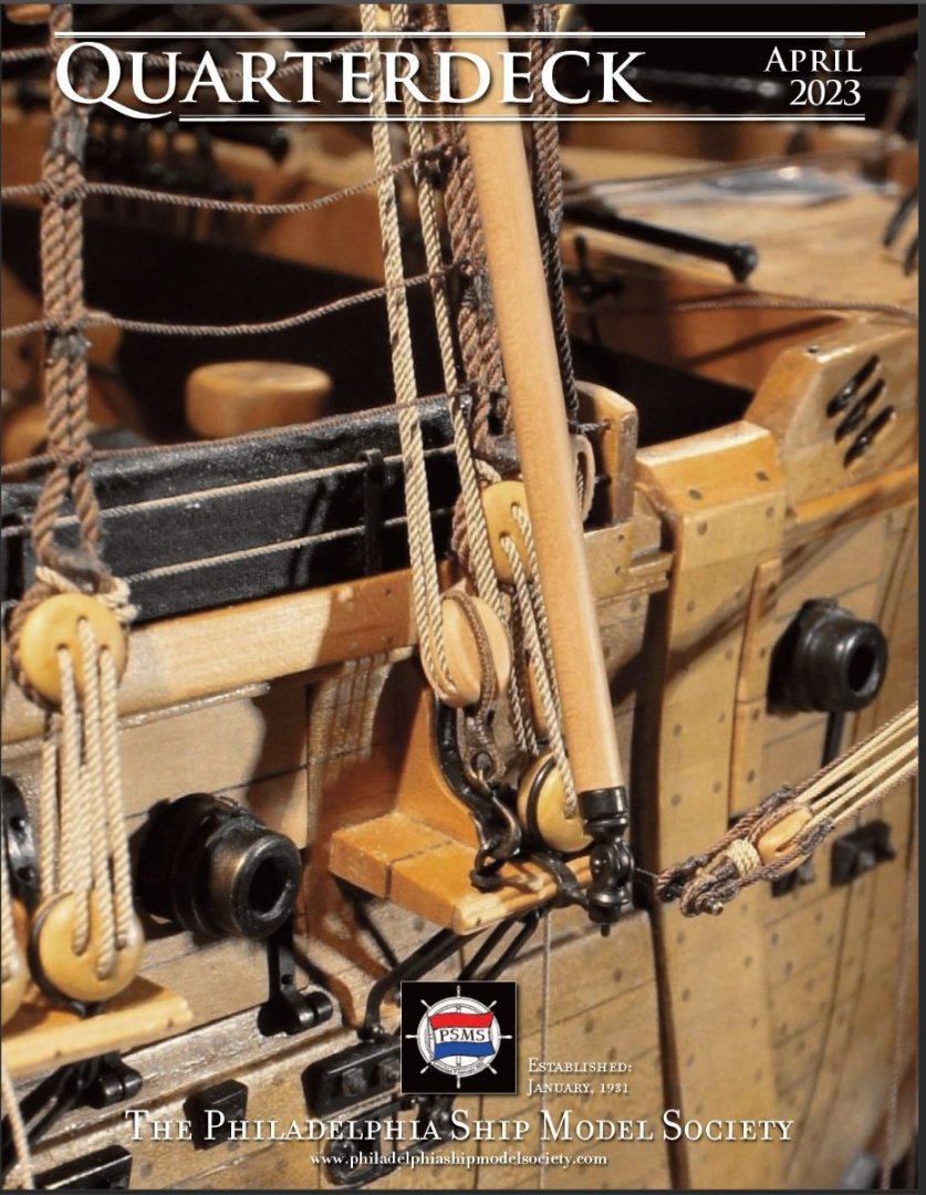
Something else in between...😀 Ron Neilson of the Philadelphia Ship Model Society asked me if they could use a detail photo of my La Créole as the cover photo for their next club newsletter "Quarterdeck" in April. Of course I was happy about the interest in my model and agreed. This is what the cover looks like: If interested: www.philadelphiashipmodelsociety.com
-
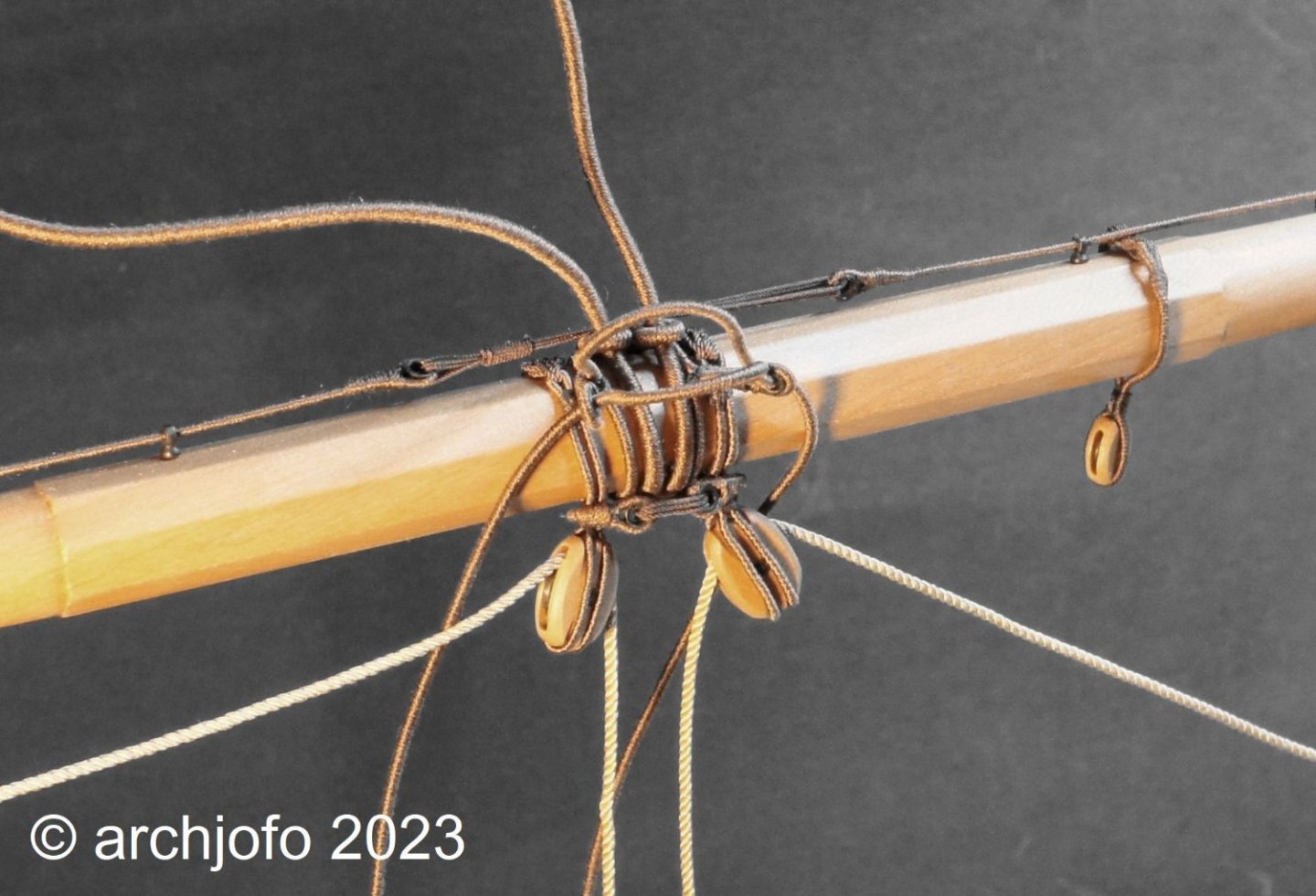
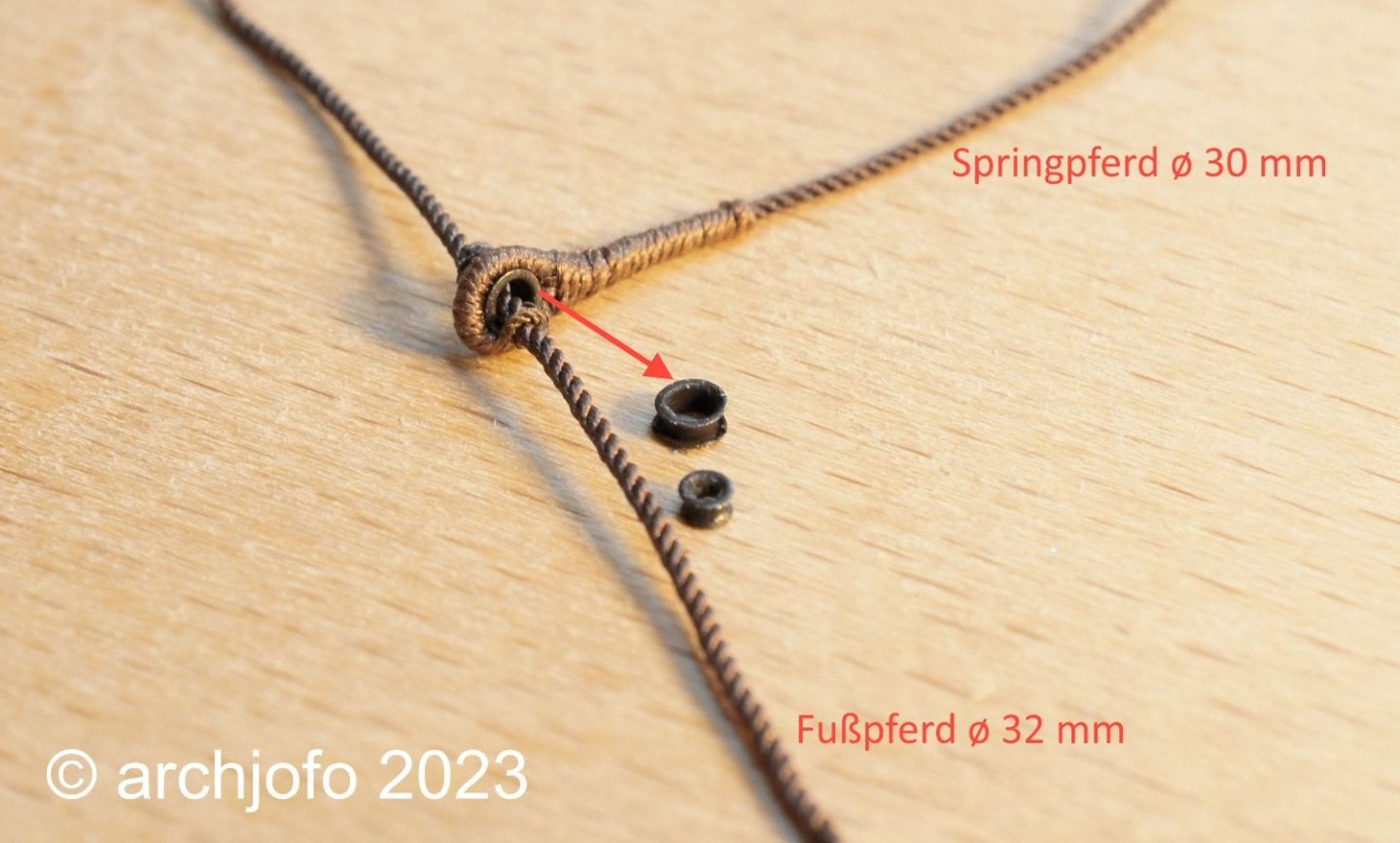
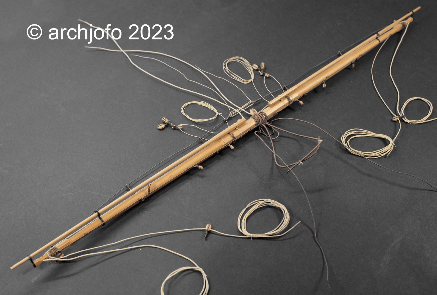
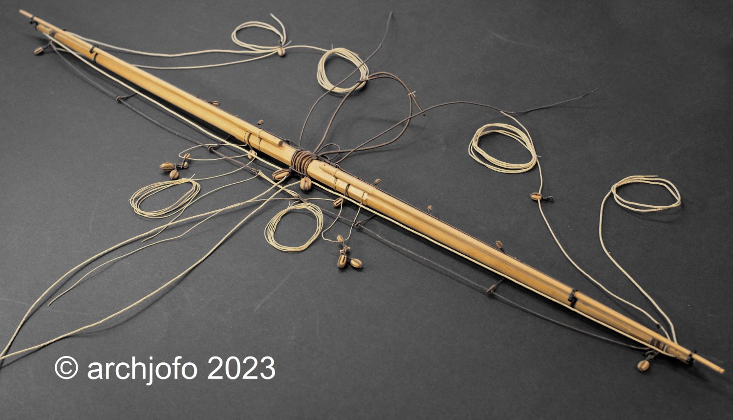
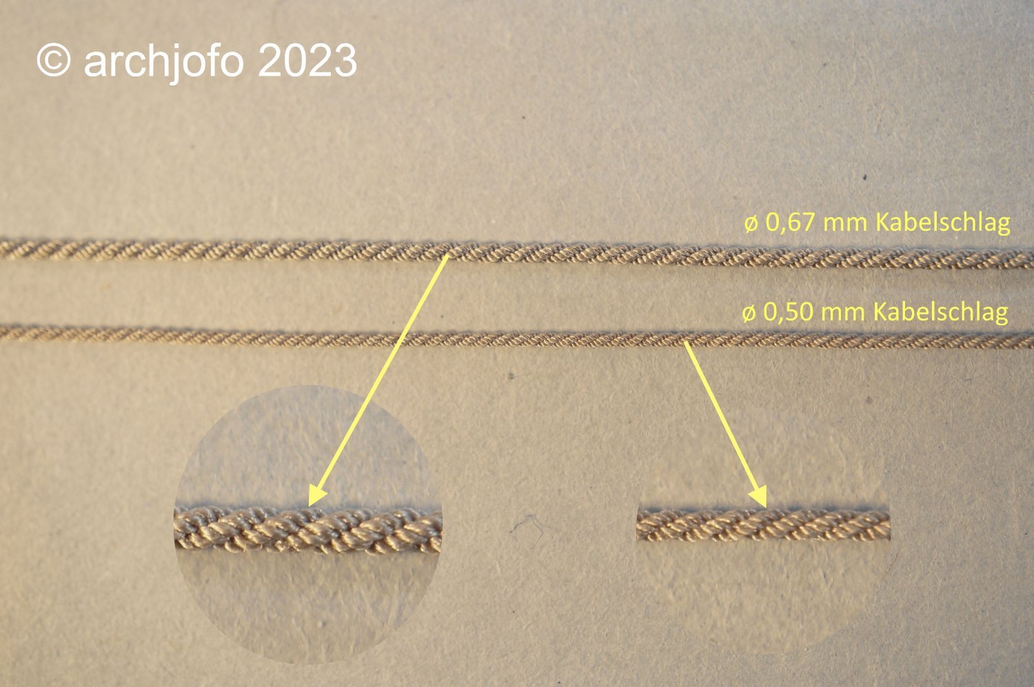
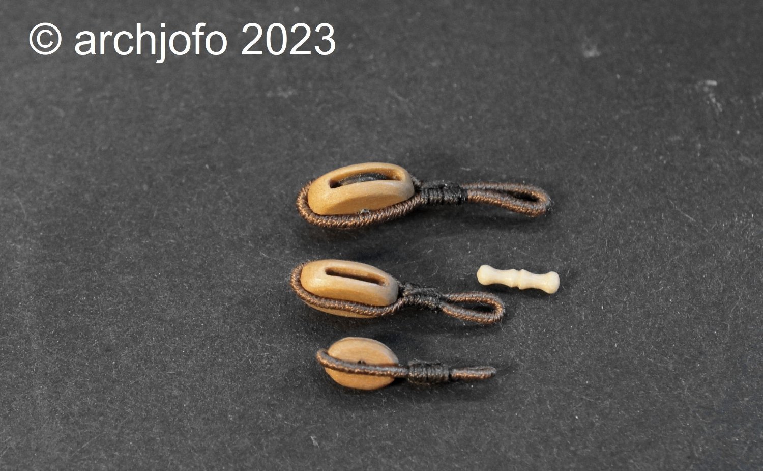
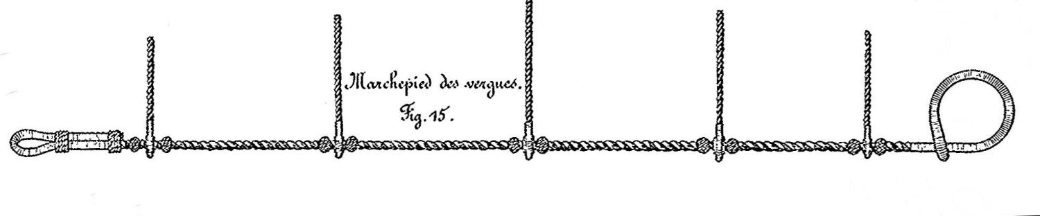
@dvm27 @Testudo @uss frolick @bdgiantman2 @druxey @jdbondy @hollowneck Hello, I am very pleased with the lively interest in my report. I also thank you for the positive feedback and the nice comments. Of course I am also grateful for the many LIKES. Continuation: Equipment of the lower yards - Footropes and stirrups - Marchepieds et étriers As often practiced, I also try to clarify the implementation of details for the foot and jumper horses by making a sample specimen. According to the specifications and the description from the monograph, the two-piece foot horses of La Créole consisted of tarred cordage, taken with spliced eyes over the yardarms. Thimbles were spliced into the inner ends and lashed to the center of the yard by means of lanyards. In the main yard, the rope for the footrope had a diameter of 32 mm according to the monograph. The ropes for the stirrups are given with a diameter of 30 mm. Source: Monograph on the La Créole by J. Boudriot For the execution of the foot horses on the model I orientate myself on a drawing from the atlas. I received corresponding information from G. Delacroix, for which I am very grateful. Source: Detail from Atlas du Génie maritime, annexe No. 1, Pl. 1 The first test piece shows that the used thimble with ø 2.1 mm appears much too dominant in the model scale. The smaller thimble with ø 1.5 mm, however, is too small for the rope thickness ø 0.67 mm. To be able to make a size in between, I am currently missing the appropriate brass tube, which I have already ordered in the meantime. So I will now bring forward the production of the other blocks for the main yard. To be continued ...

-
@jdbondy @druxey Hello, thank you for the encouragement, also I would like to thank the others for the many LIKES. Continuation: Equipment of the lower yards - Quarter blocks - Poulies d'ecoute Before I continue with the footropes according to my announcement, there was one small thing to add that I almost forgot. It is a strop with lashing that holds the quarter blocks in place. Due to the deflection of the sheets, these blocks would otherwise move towards the yardarm. See you soon ...

-
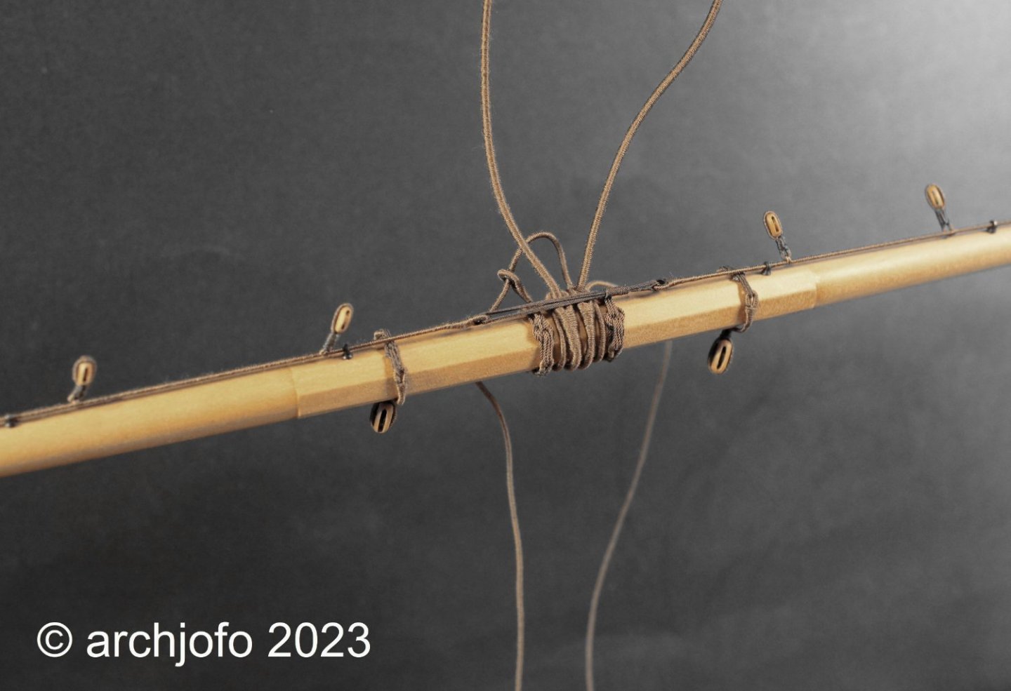
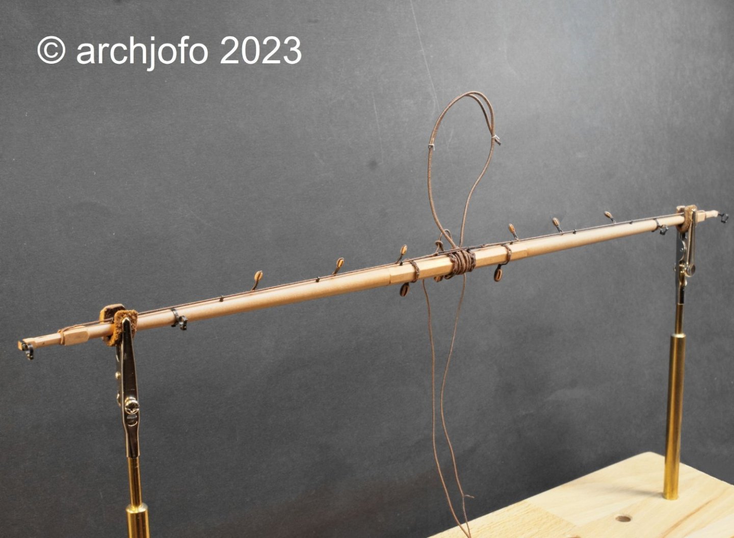
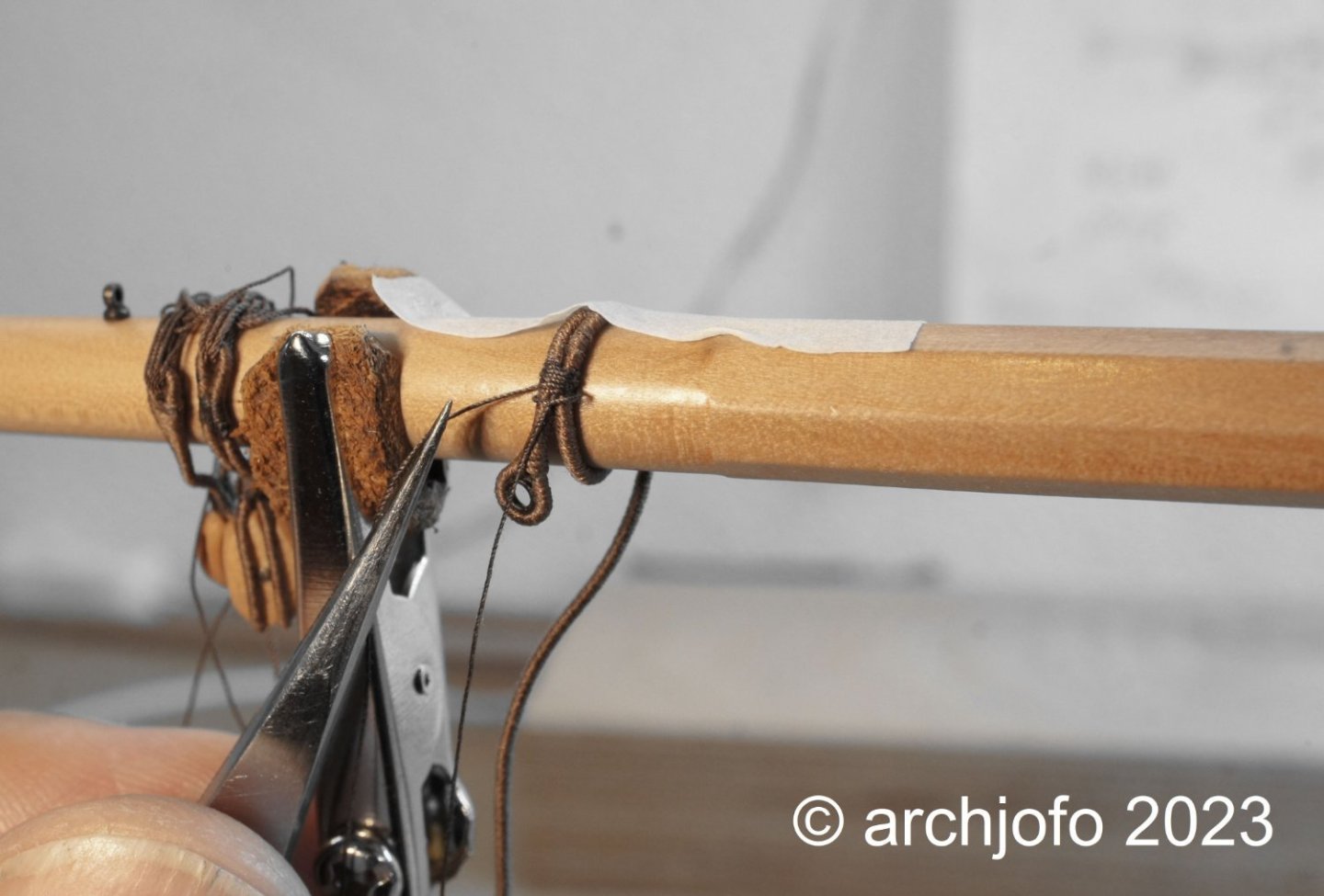
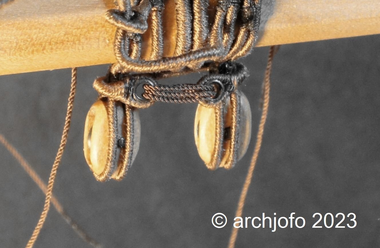
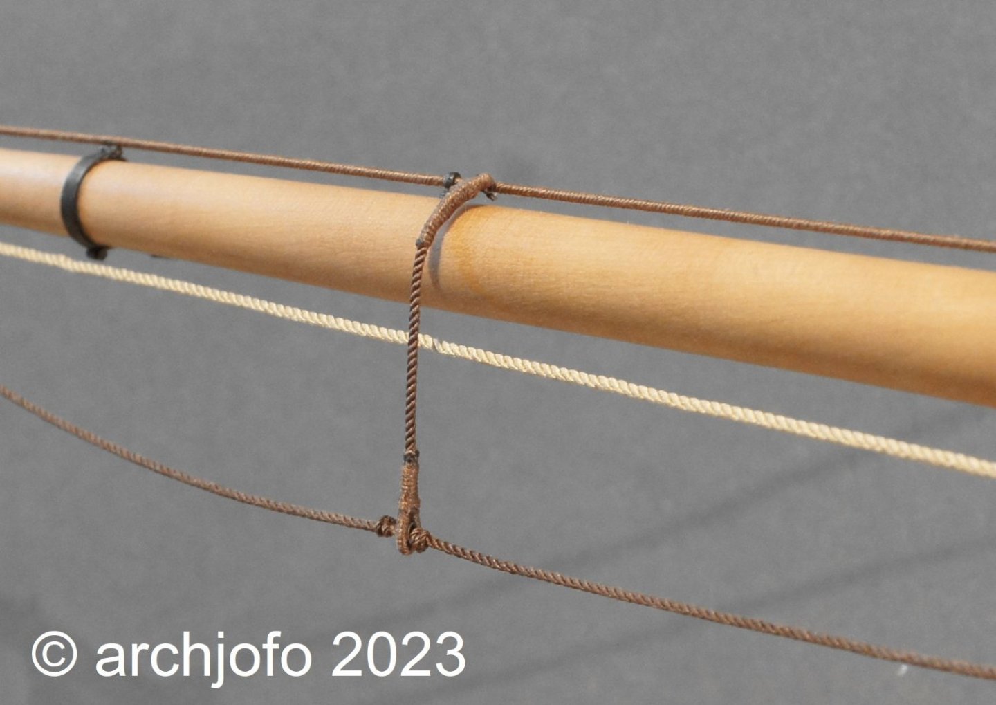
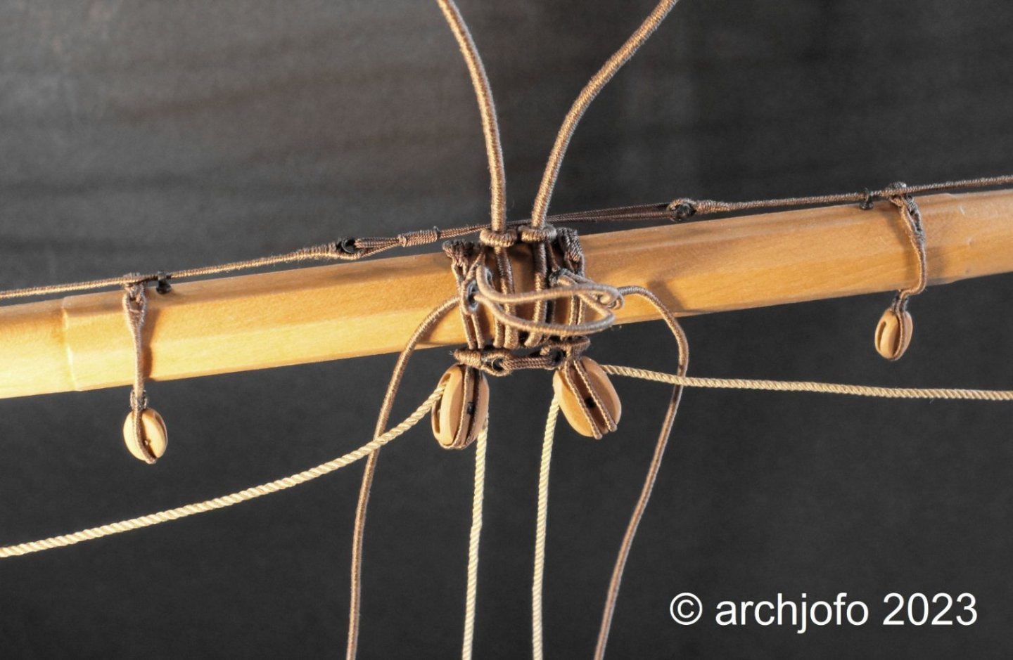
@dvm27 Hi Greg, I totally misunderstood that, sorry. For these eye splices, I outlined the process in connection with the production of the stays in my analogue notebook a long time ago. I hope this makes the process clear to you. @jdbondy Hi JD, at least I was able to fully answer your original question with the sketch. And here's a little update: Continuation: Equipment of the lower yards - truss pendants and jackstags - Drosse d´une basse vergue et filière d`envergure According to the announcement I made the truss pendants for the lower yards, especially for the main yard. The two-part truss pendant for the main yard consisted of two ropes, each with a diameter of 37 mm. Thimbles were spliced into the ends of the served ropes. As can be seen in the following picture, these ropes were placed around the main yard and secured with a lashing. The respective counterparts are then pulled through the thimbles later when assembling the yards on the model and further guided through the sheaves in the trestle trees in the direction of the mast cap and lashed there with a tackle. In order to pull in the jackstays, the eyebolts that had been made some time ago had to be attached in advance. To ensure correct alignment of the holes for these bolts on the yard, I stretched a thread. As with the Paris model, I also used served ropes for the jackstays. These were placed on the yard arm with the eye on grommet strop as abrasion protection. With the thimbles integrated into the inner ends of the jackstay, the two halves can be connected in the middle of the yard with a lanyard and stiffened Presently I am preparing making the footropes. Here, too, a few points of detail need to be clarified. To be continued soon...

.thumb.jpg.0e1f75c63e061c434e90472f2672725a.jpg)


.jpg.da3178f203fb76e997700b947e249a24.jpg)