HOLIDAY DONATION DRIVE - SUPPORT MSW - DO YOUR PART TO KEEP THIS GREAT FORUM GOING! (89 donations so far out of 49,000 members - C'mon guys!)
×

archjofo
-
Posts
1,498 -
Joined
-
Last visited
Content Type
Profiles
Forums
Gallery
Events
Everything posted by archjofo
-
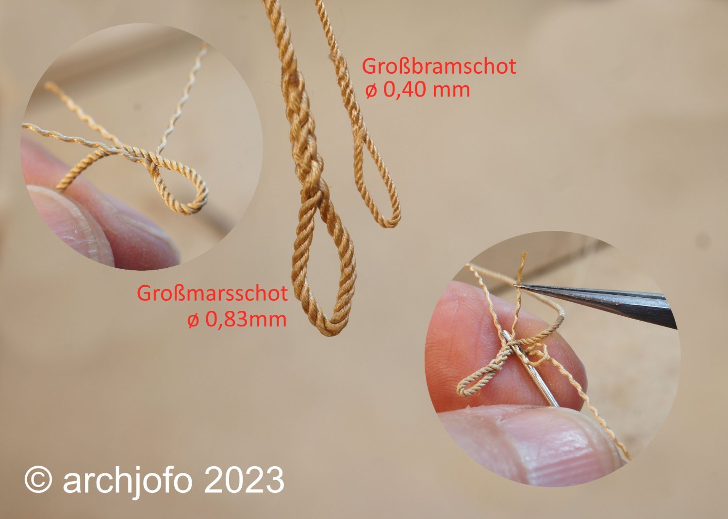
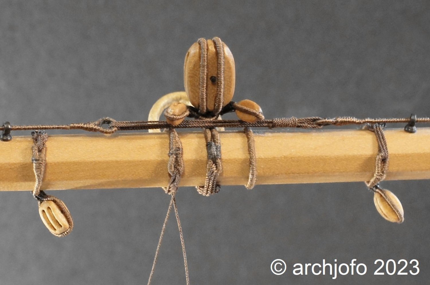
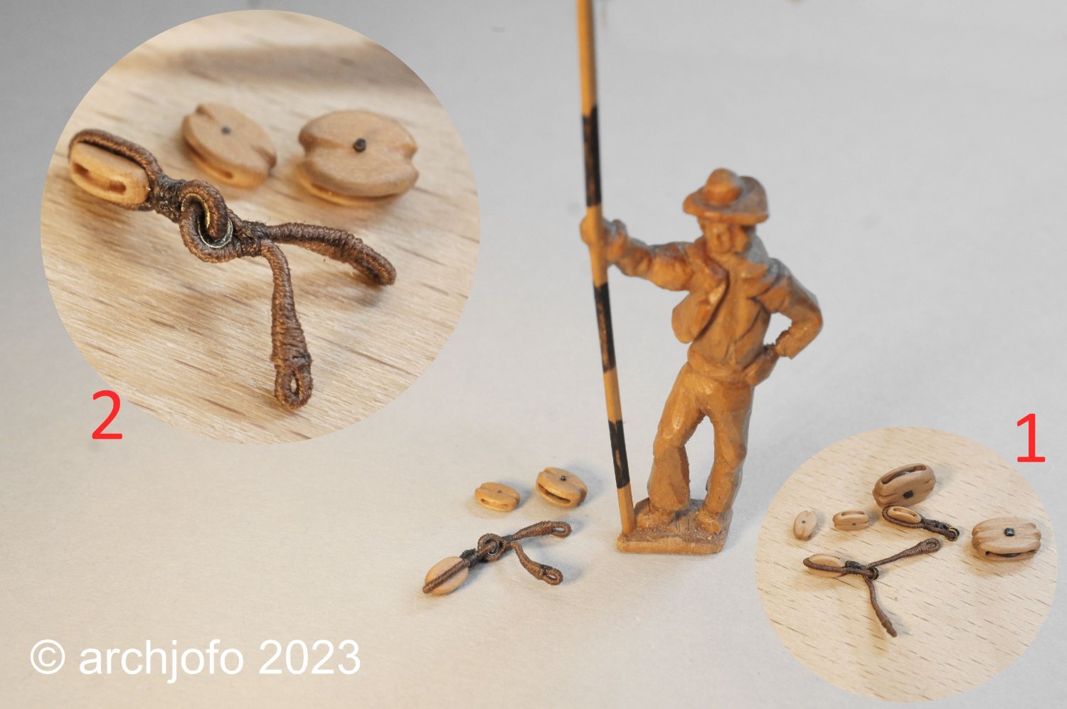
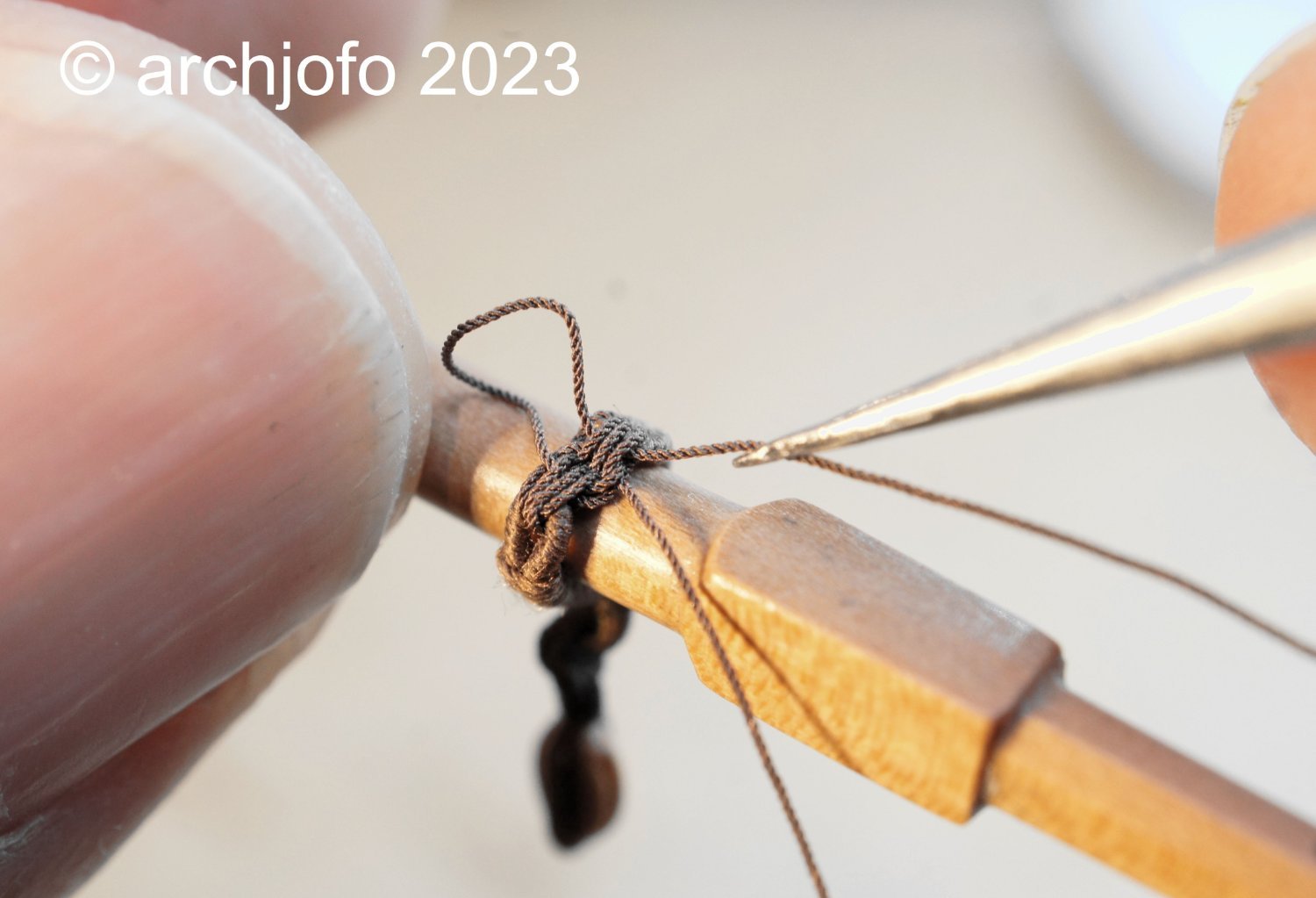
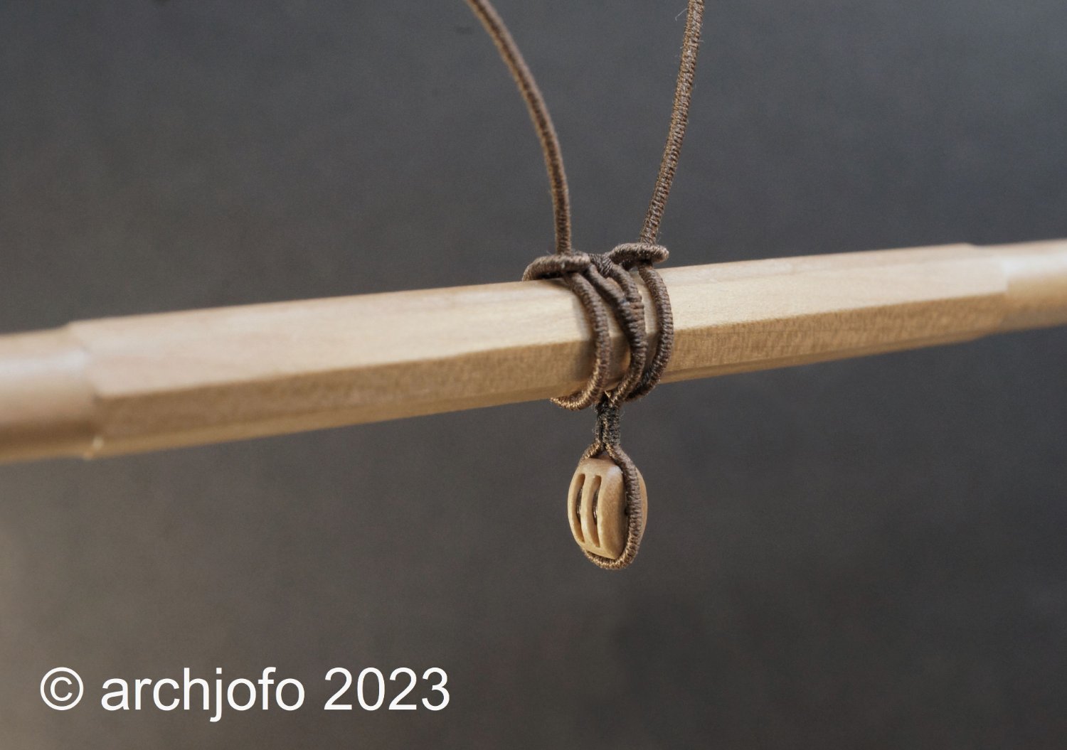
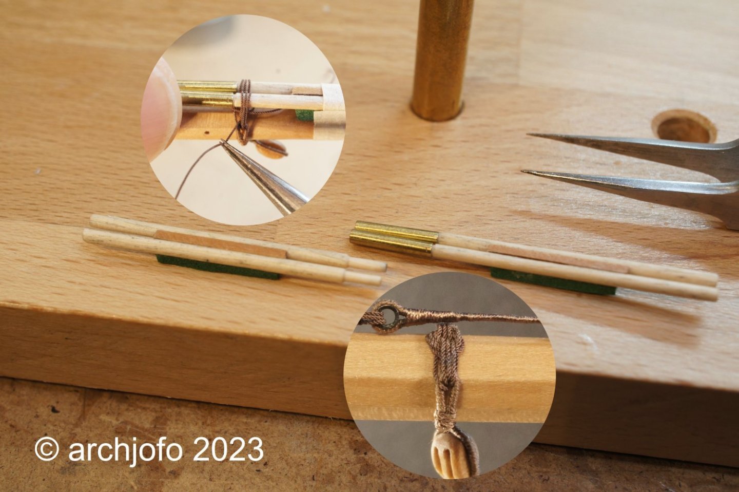
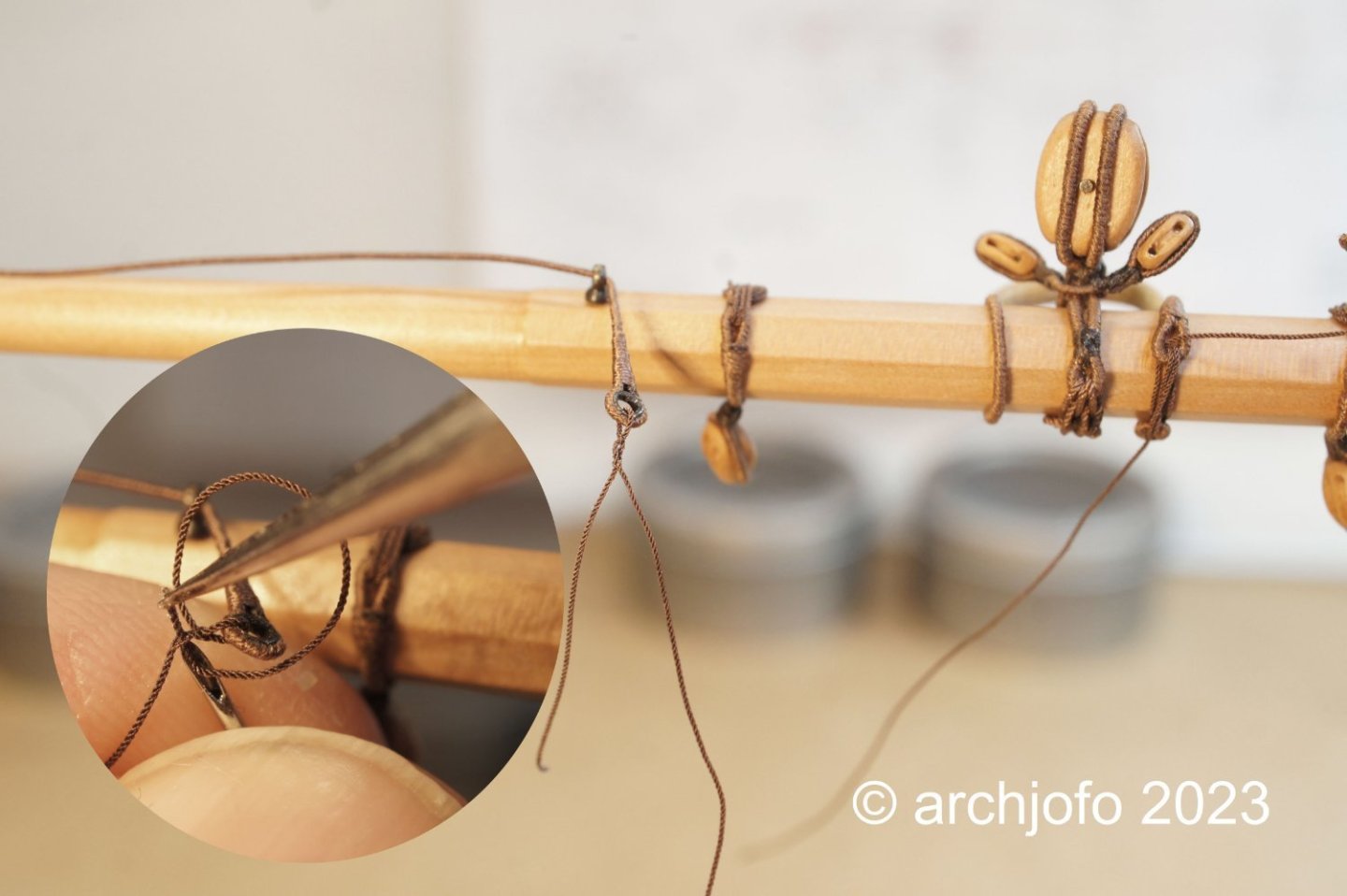
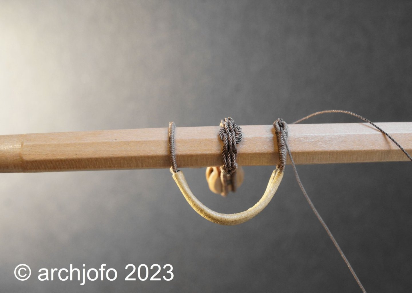
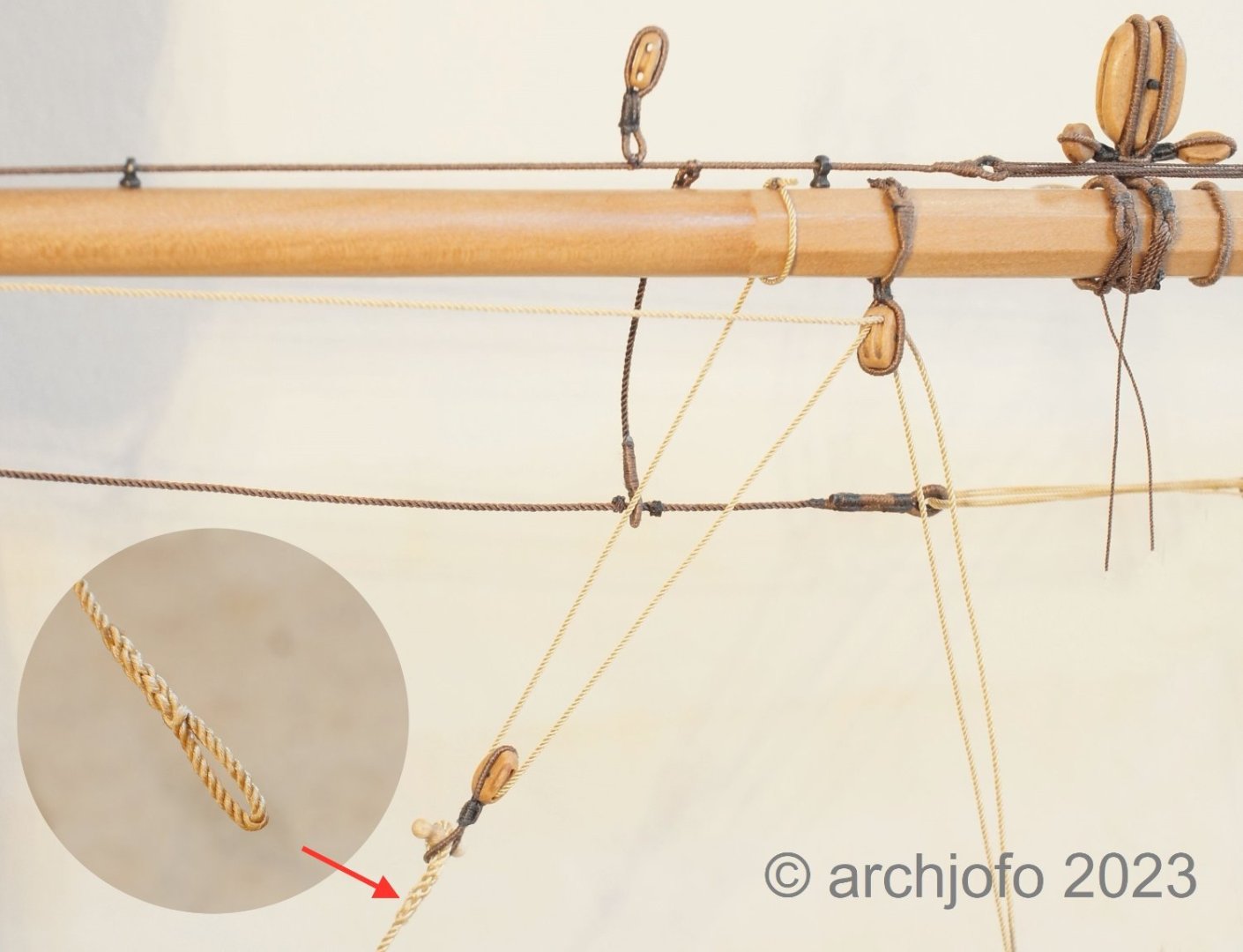
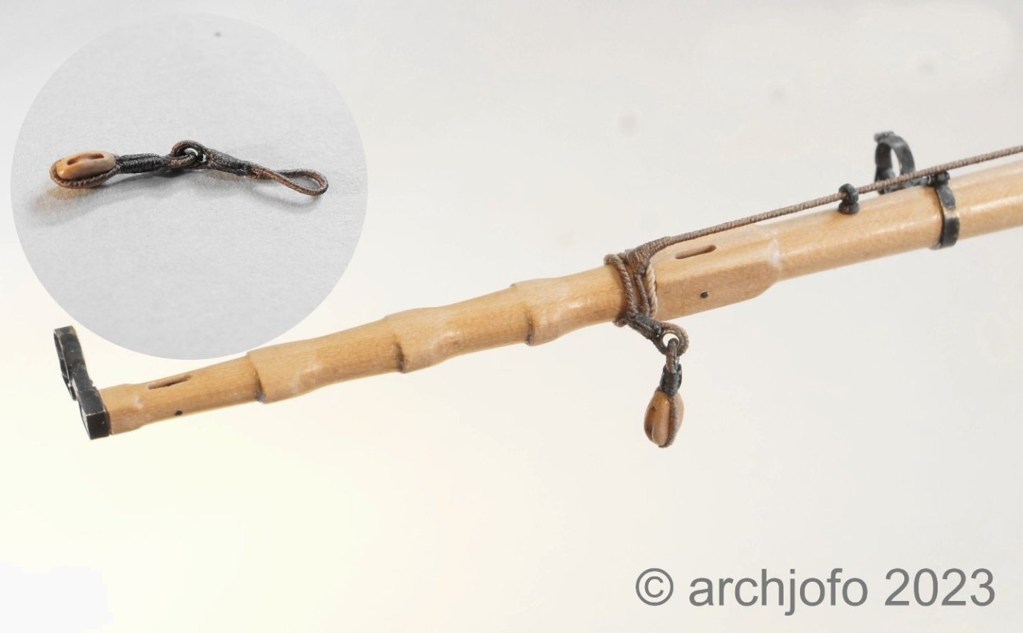
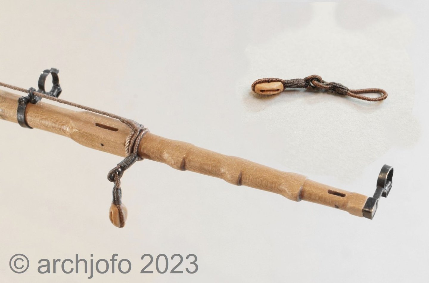
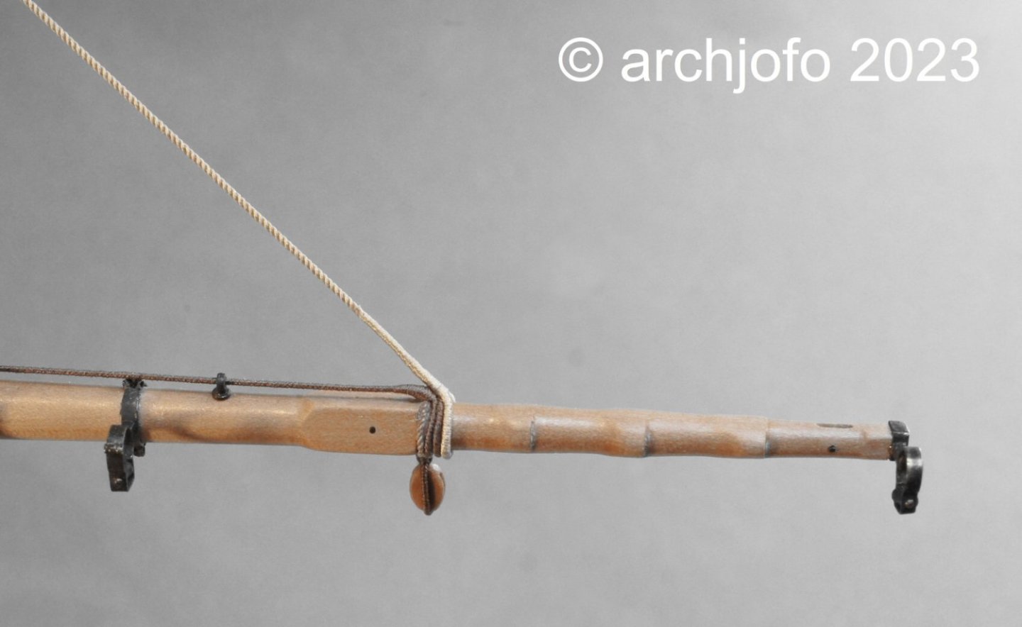
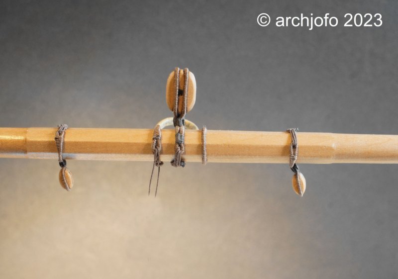
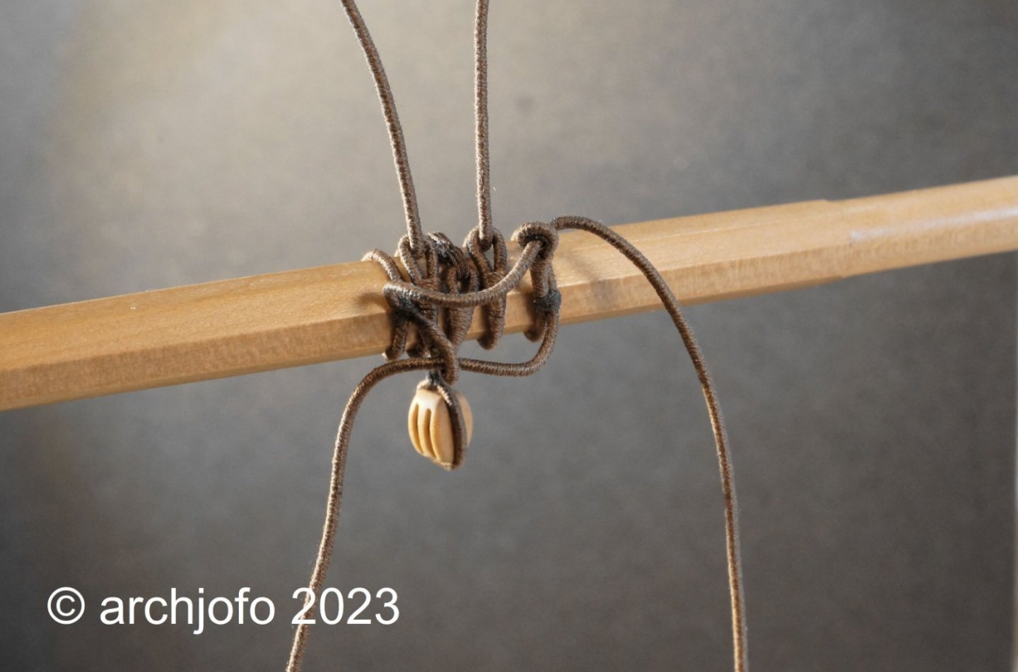
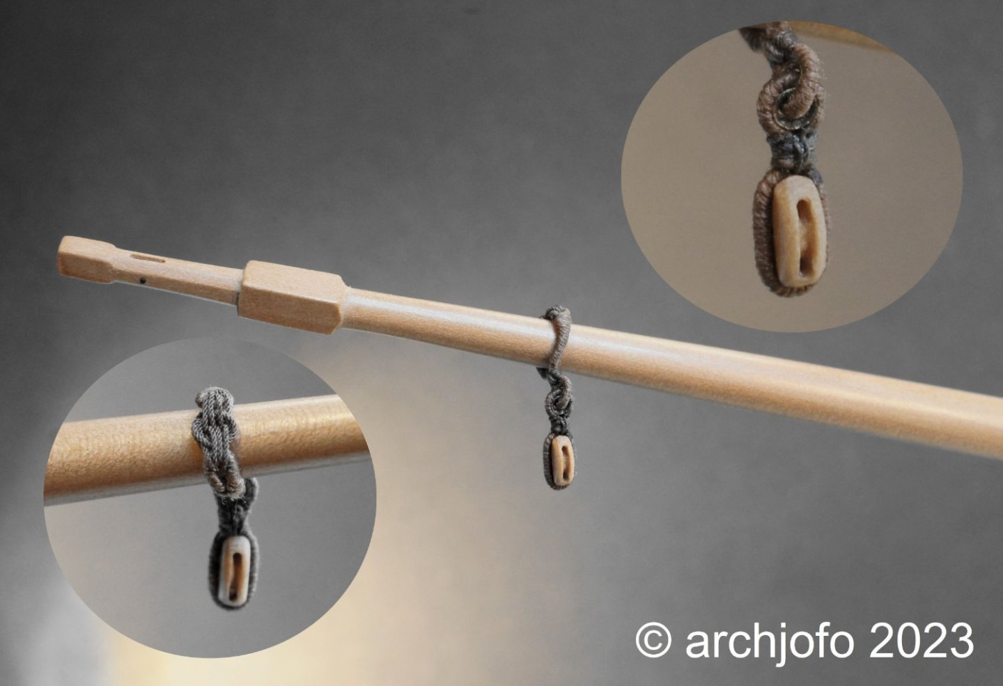
 @Vladimir_Wairoa Hi, thank you very much for your kind words. Continuation: Equipment of the Fore topsail yard – quarter blocks / Poulies d'ecoute et Poulies de cargue point As with the fore topsail yard, the clew lines and sheets each run over a double block, also known as a quarter block. Here too, I attached these double blocks using rose lashing. As I pointed out some time ago, I made a suitable tool that makes creating a rose lashing easier. I saw this and copied it from our model builder colleague. I don't want to adorn myself with other people's feathers here... Fastening the quarter blocks was followed by pulling in the rope at the jackstay, which was attached to a thimble using a simple eye splice, as can be seen in the following picture. And last but not least, the result of this work section. Sequel follows …
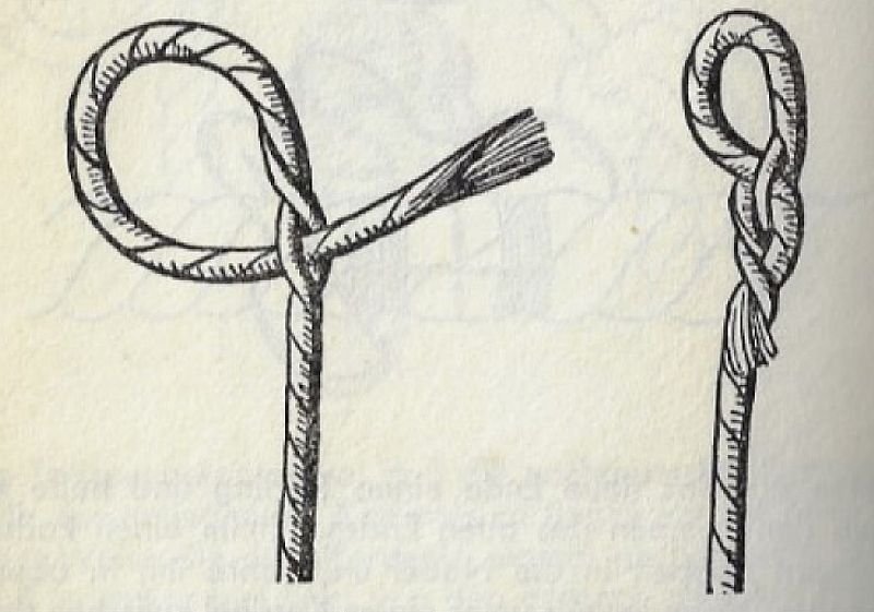

-
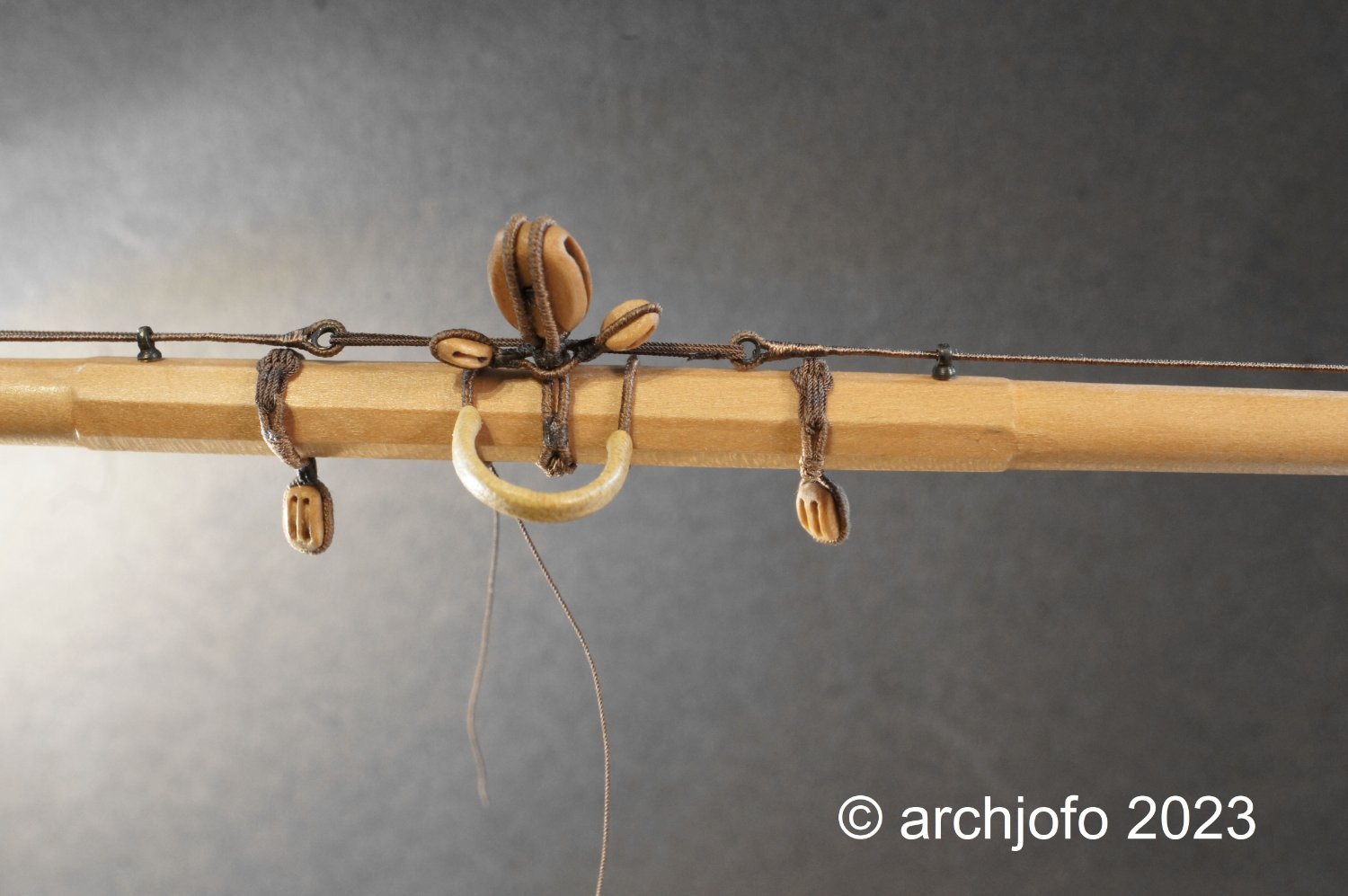
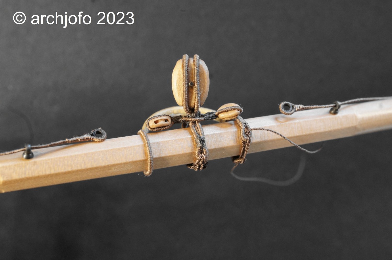
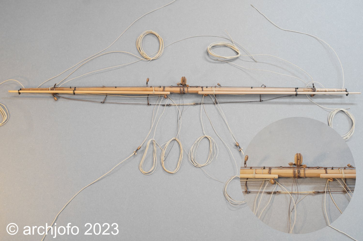
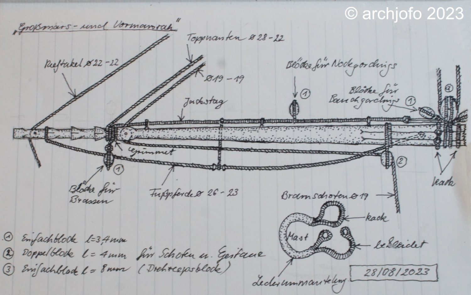
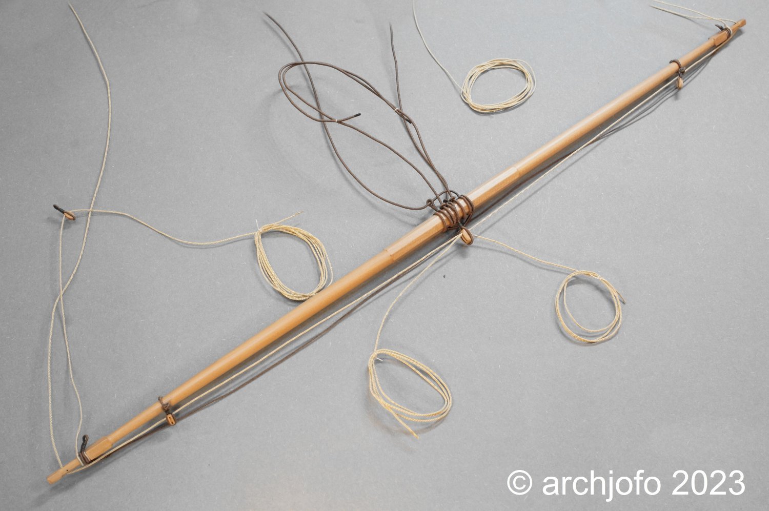
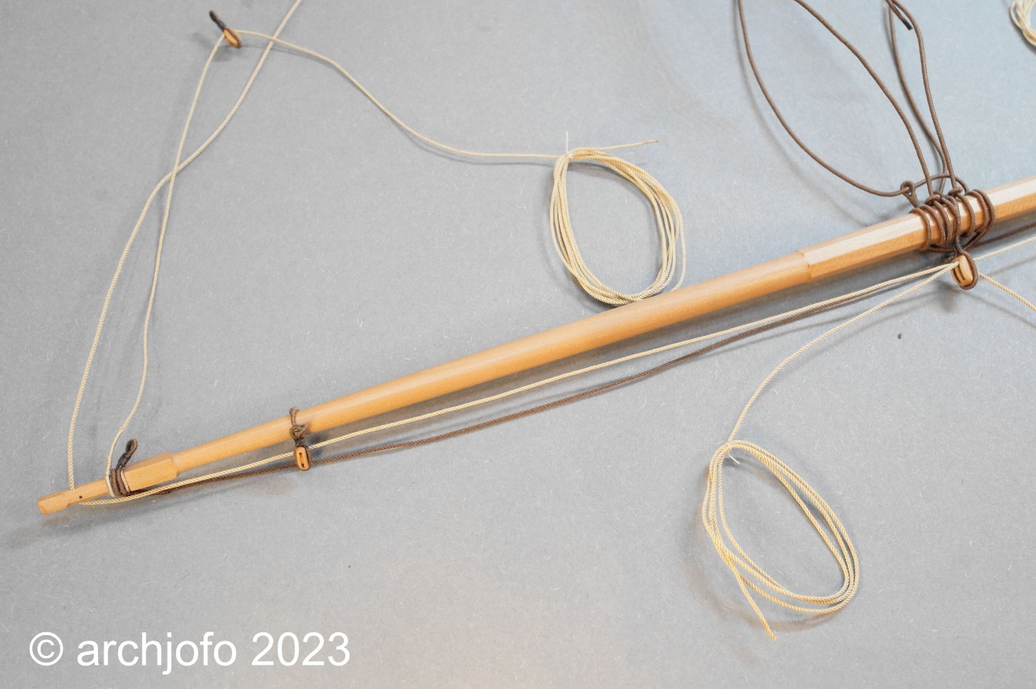
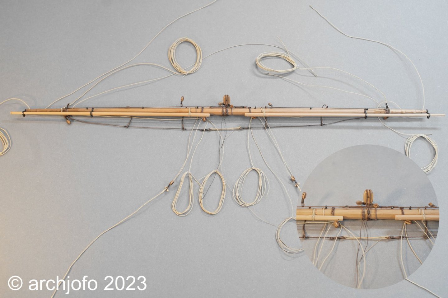
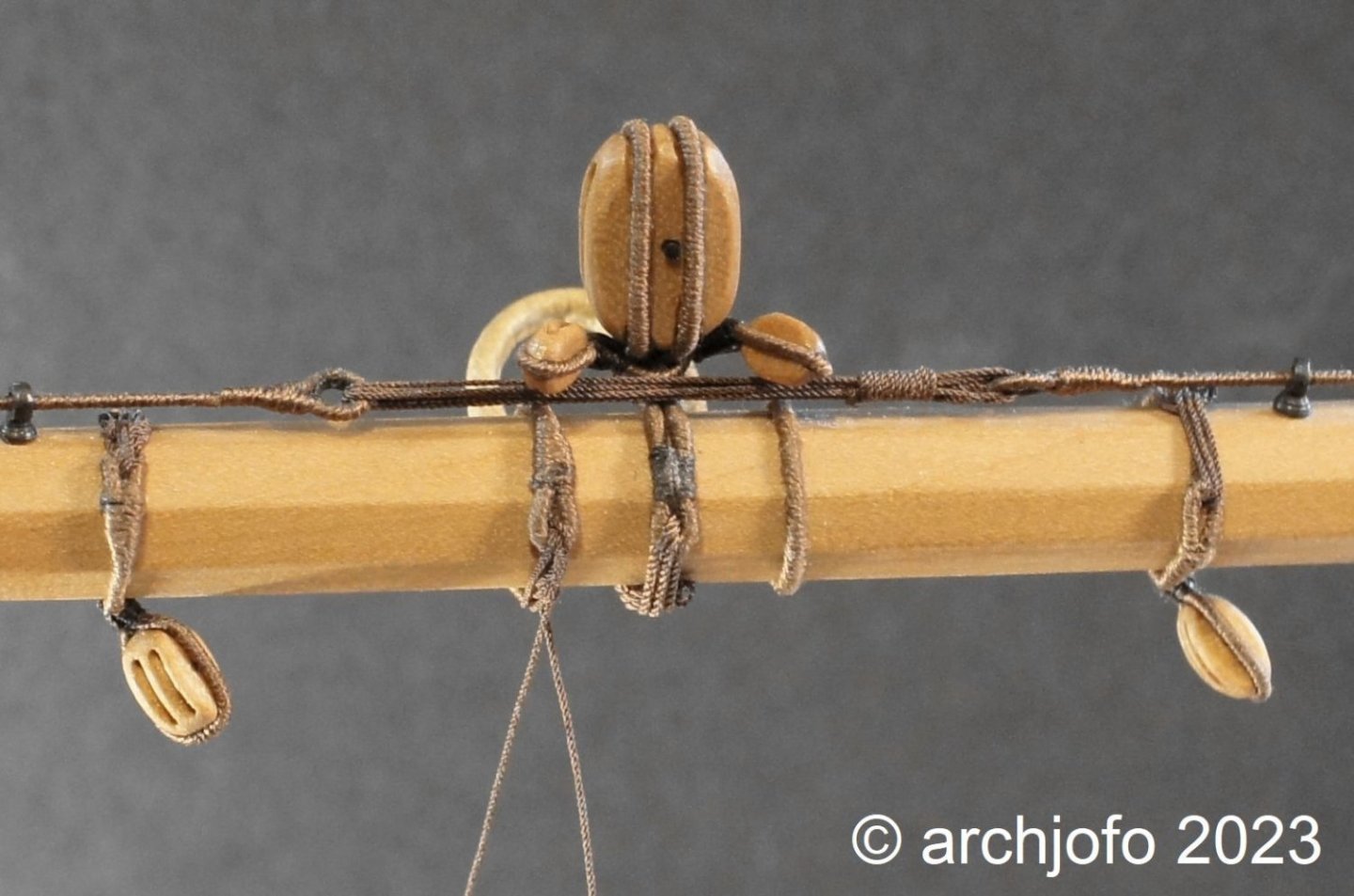
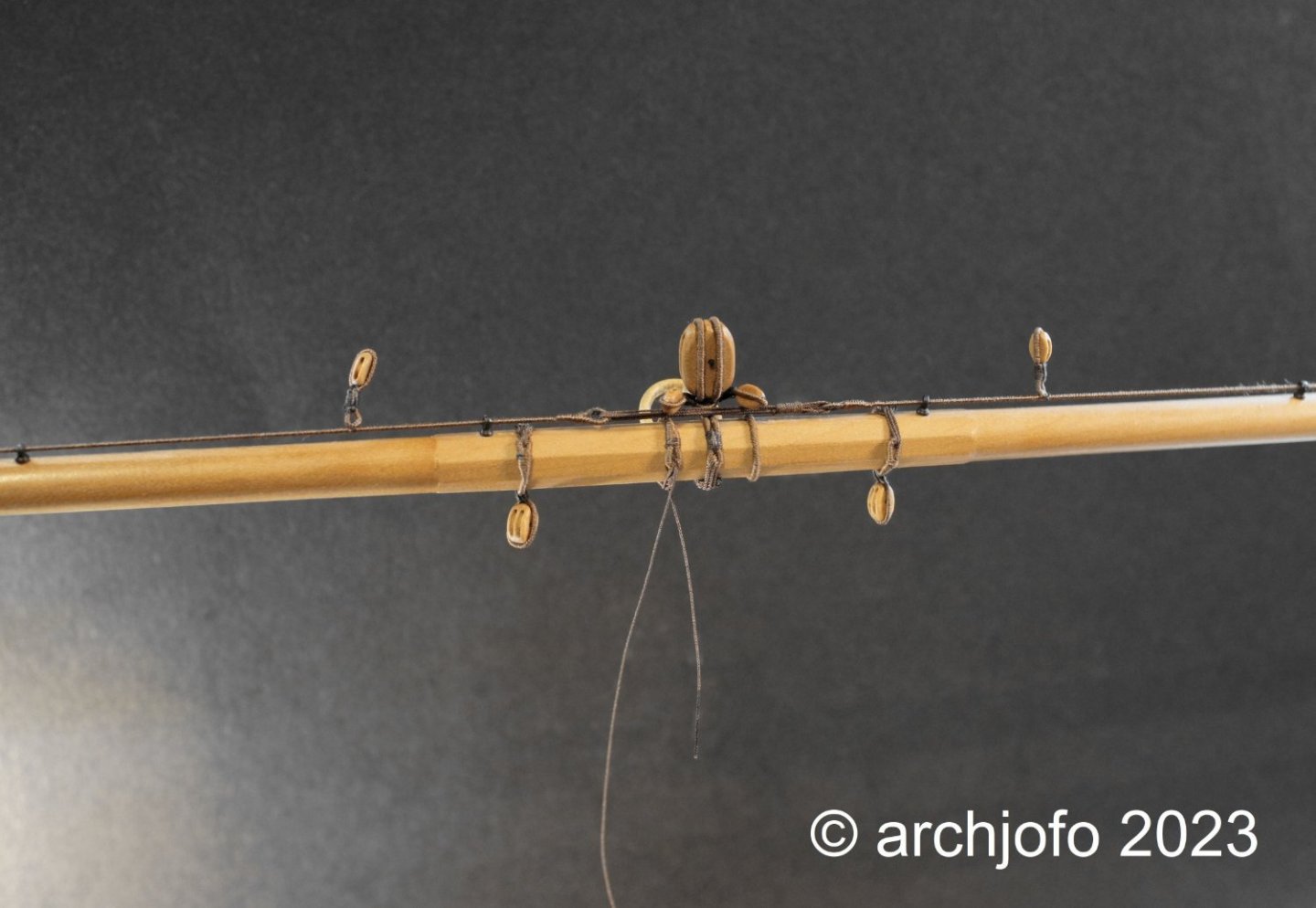
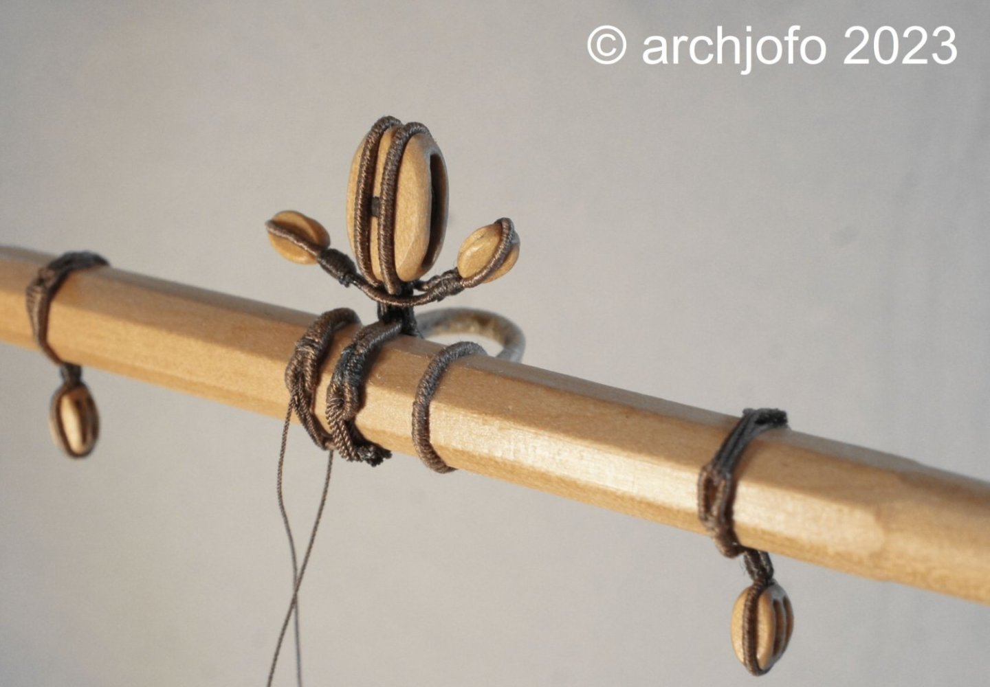
@jfhealey @CiscoH @jose_b Hello, I'm always happy to receive praise for what you do. Thank you very much for that. But of course I would also like to thank everyone for the many LIKES. Equipment of the fore topsail yard – fore topsail yard truss, fore topsail yard tye block, quarter blocks and blocks for buntlines, Jackstay/ Racage d'une vergue, poulie d'itague et poulies de cargue fond, filière d'envergure According to my announcement, I am currently working on the equipment of the fore topsail yard. As already mentioned, this is done in the same way as the equipment for the main topsail yard, but in an adjusted size. The following illustration is intended to show how the truss of the fore topsail truss is covered with leather and how the simple block strops are dressed. The tye block with the attached blocks for the buntlines (L=3.5 mm) is also shown, as is also the enlarged image in the next photo. The tye block (L = 7 mm) was temporarily attached to the fore topsail yard using rose lashing and the yard truss was temporarily lashed in place. And as you can see in the last picture, I have already made and attached the jackstays. Only the rope in the thimbles still needs to be pulled in, which of course only makes sense after the double blocks for the clewlines and sheets have been secured. But more about that soon…


-
Hello Greg, thank you very much for your consideration of my work and your kind words. I learned the splicing technique from a video on the internet. So I don't think I can show it better. But if anyone is interested, they can follow this LINK - Video eye splice. There are many other good videos for learning the splicing technique. I hope that I have given some inspiration.
-
Completion: Equipment of the main fore yard With the attachment of the studding sail booms, the equipment of the main fore yard was completed. This means that this yard can be placed on its side next to the others until it is finally installed on the model. Finally, a picture that shows the entire yard with a detailed section. Everything that seemed possible and sensible was attached to the yard, which will make the later rigging work on the model a lot easier. Next I will equip the fore topsail yard, similar to the main topsail yard. However, in an adapted form in terms of rope strengths and block sizes. Many rigging elements were already made with the parts for the main topsail yard. In this respect, I can assume that the new phase of work will progress a little more quickly. In addition, the research for the detailed training has also been completed. Sequel follows …
-
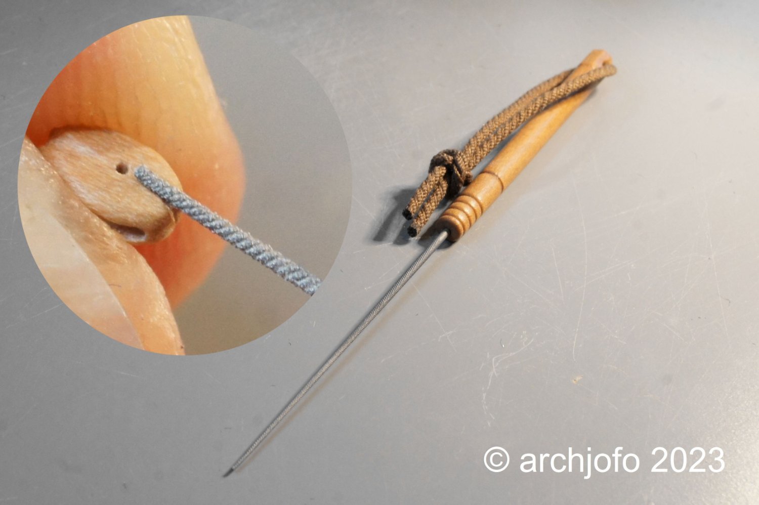
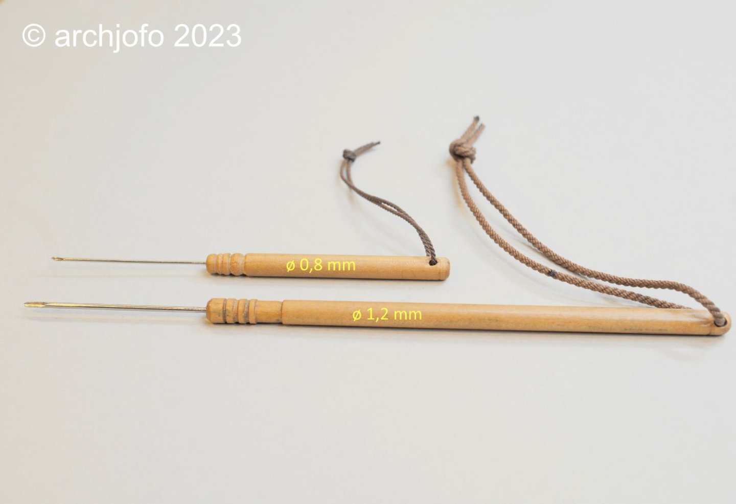
Hello colleagues, Thank you very much for your interest and the nice comments. A long time ago I made these hollow spikes from cannulas in two thicknesses. For example, I used the thinner hollow spike to make the brummel eye splices at the ends of the ratlines. With these “model spikes” it works quite well after some practice. It is recommended to make the sharp tips of the needles slightly rounded and blunt so that the thin ropes are not cut.
-
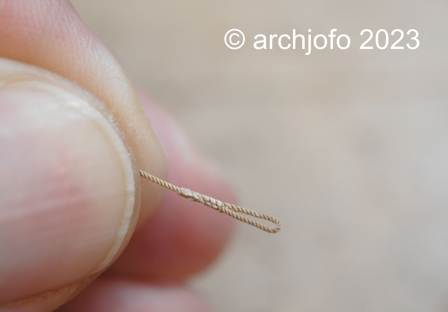
@giampieroricci Many thanks vor your nice comment, and also thanks to the others for the LIKES. Continuation: Equipment of the main topsail yard – eye splices for sheets If I remember correctly, some time ago a dear fellow model maker once described weaving linen as a “complementary meditation”. I discovered another passion by making eye splices... 😊. But seriously, making splices is really relaxing. The feeling of looking at the result also conveys a certain fulfillment, at least for me. After many attempts, I am now more or less able to make usable eye splices in almost any rope thickness. In the meantime I have formed the ends of the main topsail sheets and main topgallant sheets with eye splices so that I can later create the connection already described using a toggle on the clewline blocks or on the clewlines. Up soon …

-
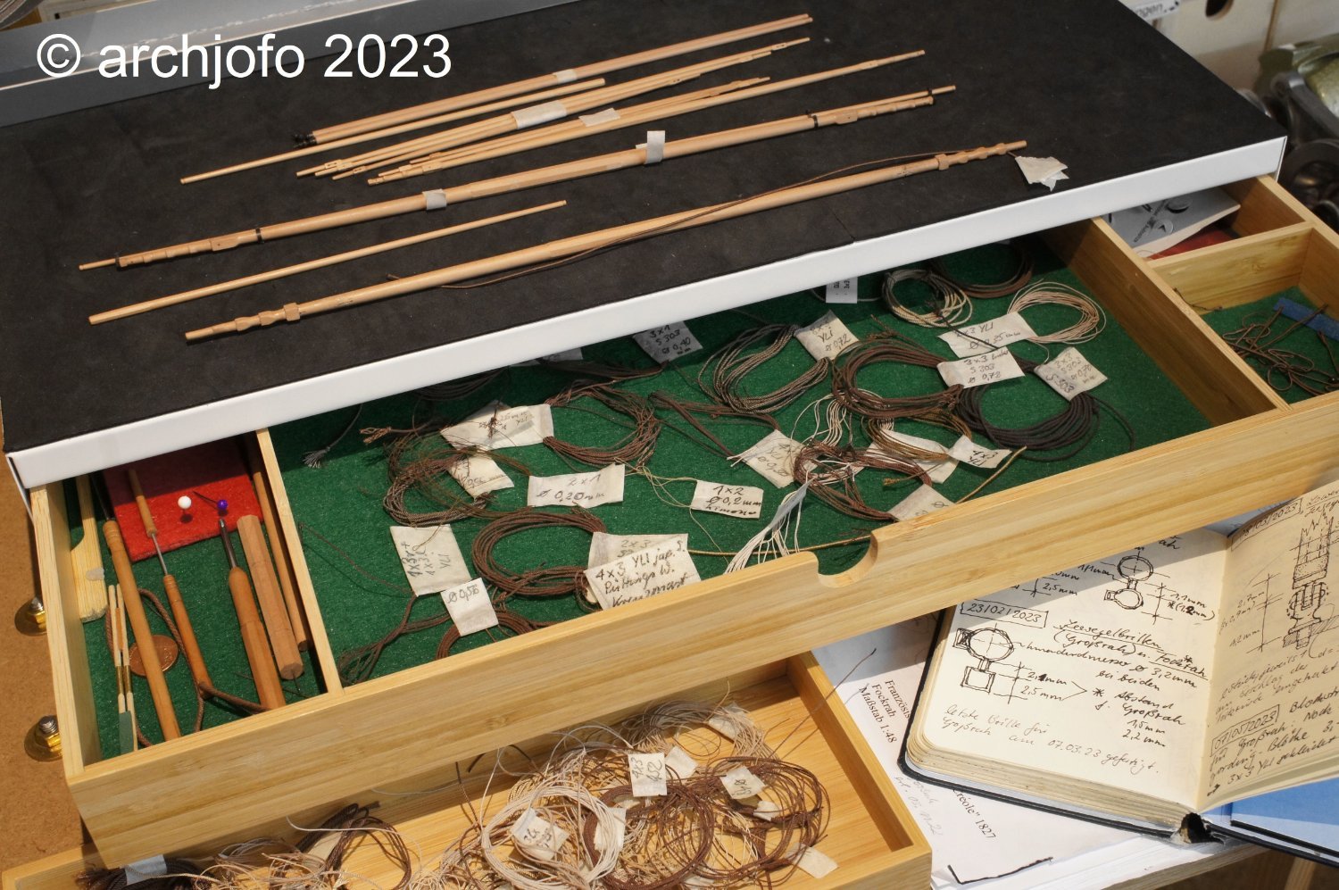
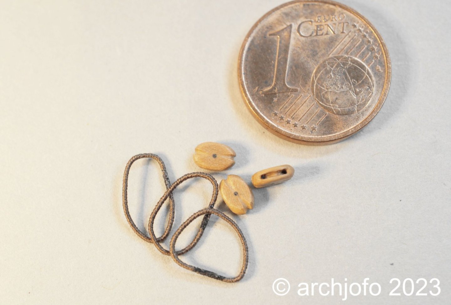
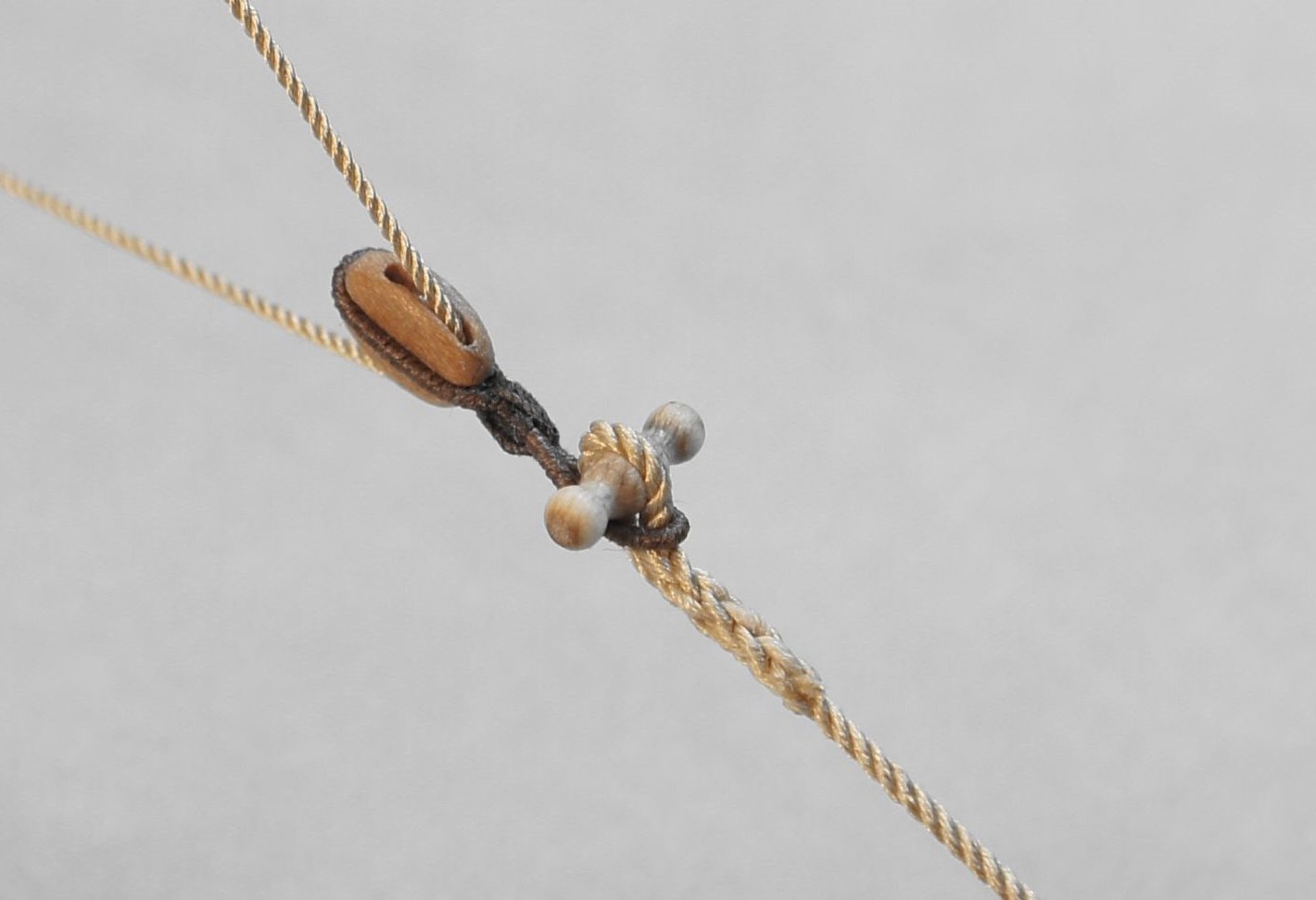
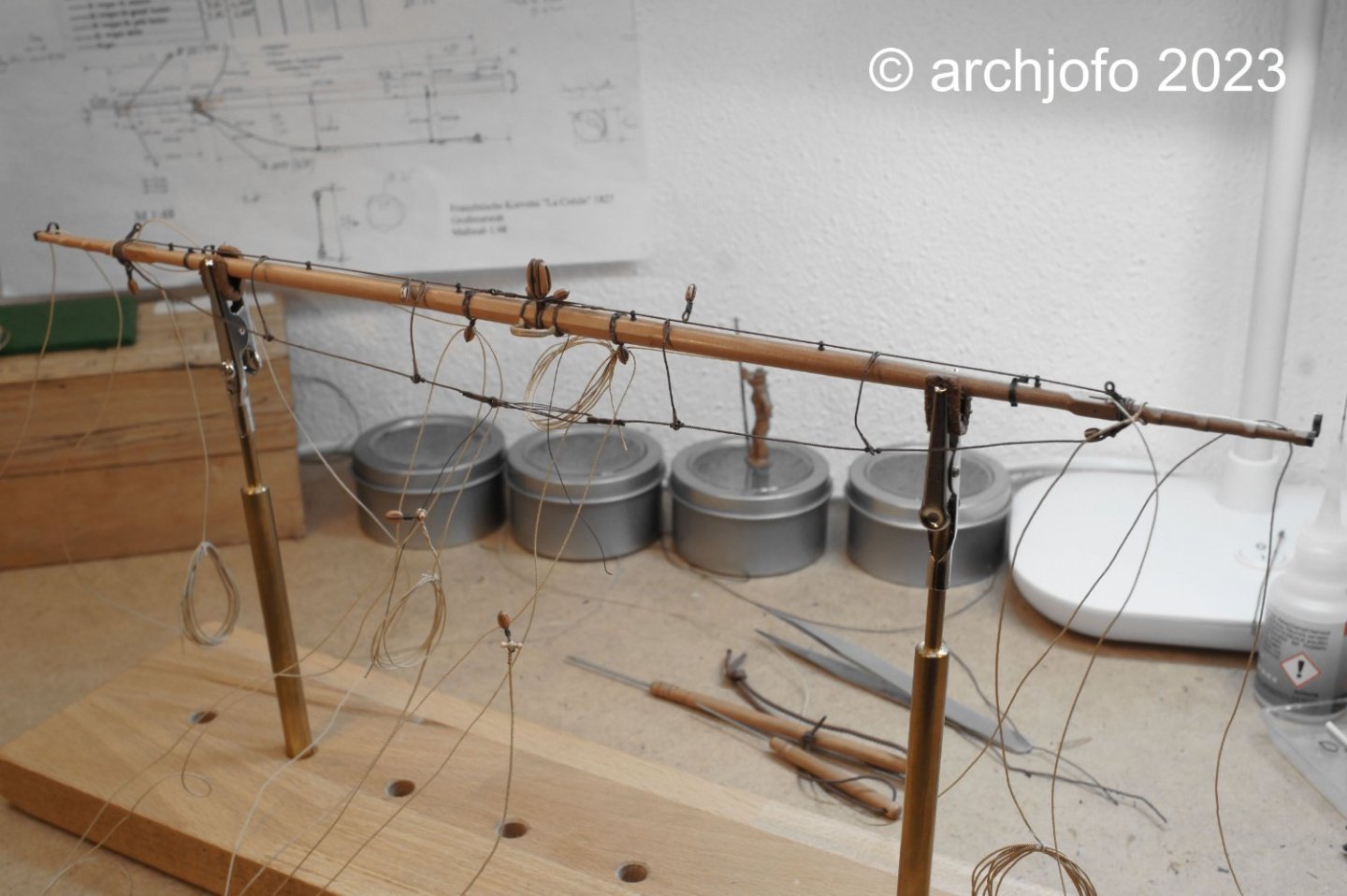
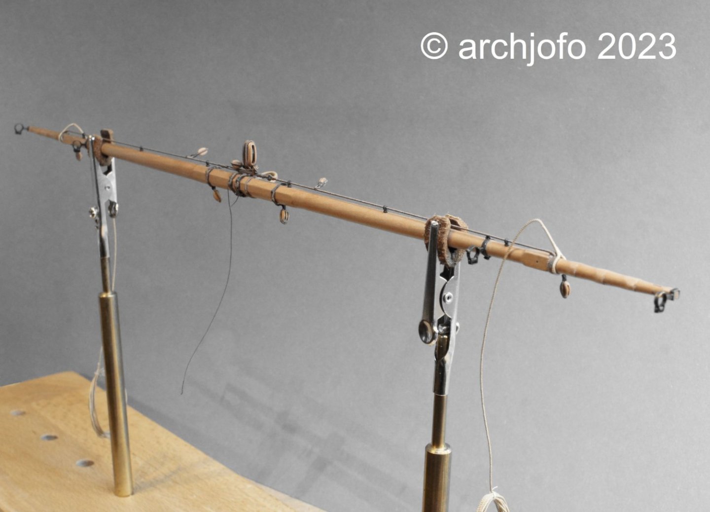
Continued: Equipping the main topsail yard - footropes and stirrups - Marchepieds et étriers etc. The garden has been "tidied up" and made ready for the winter. Everything has also been done in the house. The days have become shorter and motivation is at a high level again. So I'm continuing where I left off a good 2 months ago, with the footropes in the main topsail yard. In the meantime, I have carried out further research into the design of the footropes and stirrups for this yard and have therefore decided, contrary to my previous assumptions (see sketch in previous reports), to attach two stirrups to each half of the yard. I will therefore move the outer attachment points of the footropes further inwards. What seems important to me in this context is the fact that even with such inconspicuous details as the footropes, the following principle must be observed: the higher up in the rigging, the more delicate the rigging elements, such as ropes, thimbles and blocks, become. This is why the following picture shows the difference between the stirrups of the main yard (top left in the picture) and the main topsail yard, which is quite recognizable. On the next picture you can see the finished footropes with the stirrups of the main yard and one or the other detail in an enlargement. The footropes have a diameter of 0.54 mm for the model (original size ø 26 mm), the stirrups ø 0.48 mm (ø 23 mm). After attaching the footropes with the stirrups and the rest of the equipment, such as the brace blocks and the lifts, I also attached the sheets, clewlines and the ropes for the reef tackle. The length of the clewline blocks for the main topsail yard for the model is 4 mm, as can be seen in the next picture. The block strops are already lying next to it, ready to be tied in. Since I do not attach sails to my model, I connect the sheet ends (eye splices) to lower clewline blocks with toggle, as seen on the Paris model and various contemporary models. Apparently the French preferred to use toggles (cabillot d'armarrage) to connect the clews to the sheets. On the other hand, the stopper knot was obviously widespread among the English, at least that was my observation. Unfortunately I can't prove that. I made these little toggles from dogwood, one of the hardest native woods, which is very suitable for turning and polishing, so ideal for this purpose. The following illustration shows the eye splice of a sheet for the main topgallant sail (0.40 mm), which will later be connected to the clewlines of the main royal sail using a toggle. At the moment I'm still working on the main topsail yard, as you can see in the following picture. The last picture shows the back part of my “rigging workshop”. On the one hand, you can see the yards and spars that have not yet been equipped, and on the other hand, various rigging thread and a few rigging utensils, always ready to hand. By attaching the studding sail booms, the main topsail yard will ultimately be fully equipped. Sequel follows …


-
Fantastic work !
-
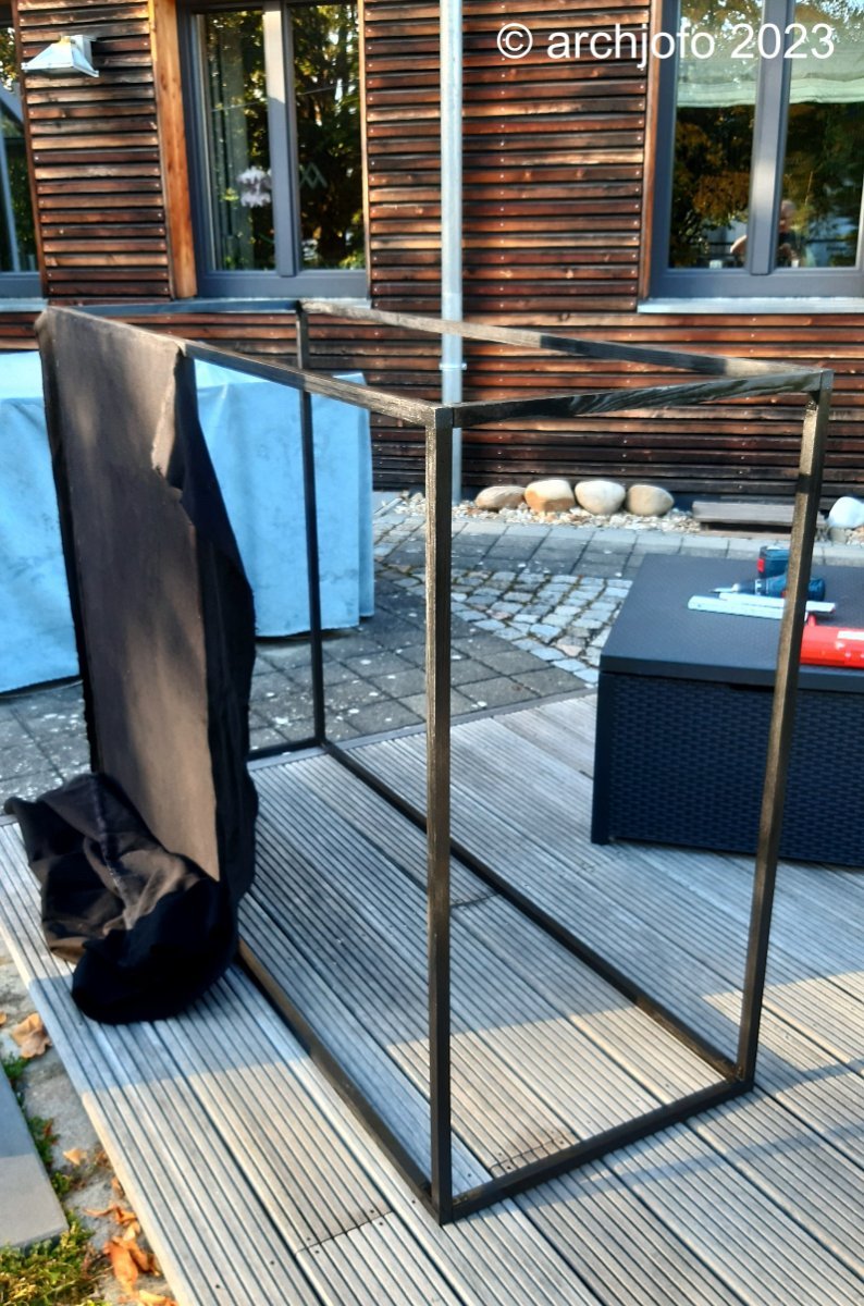
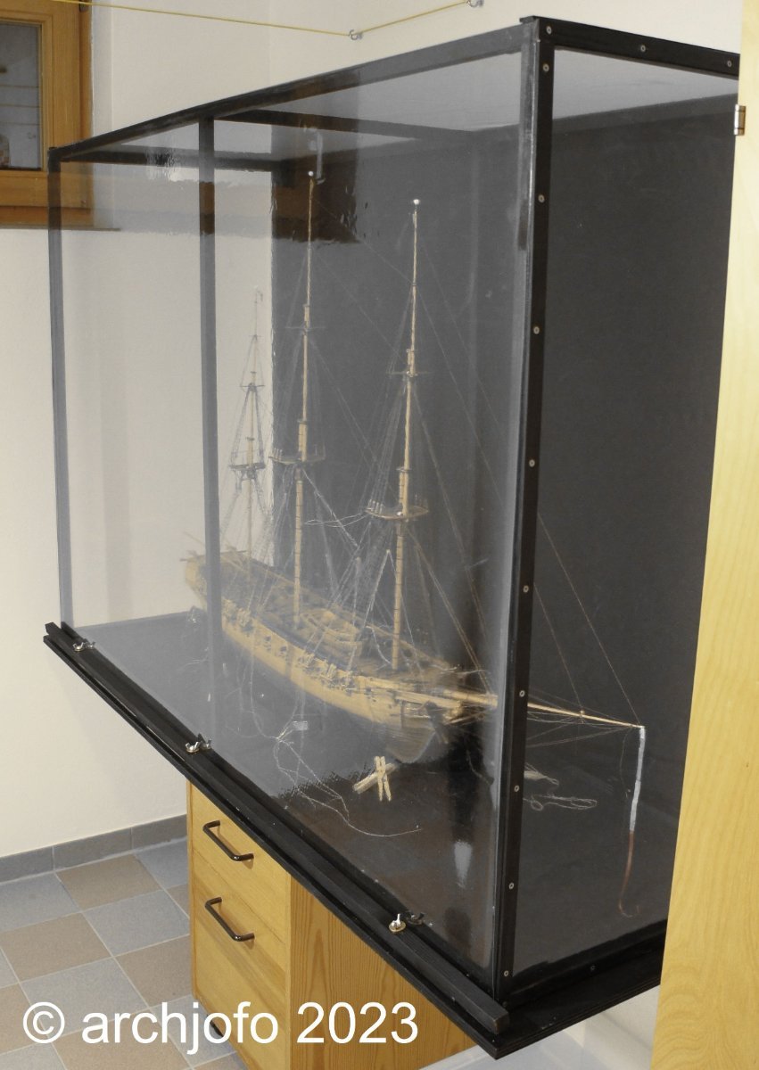
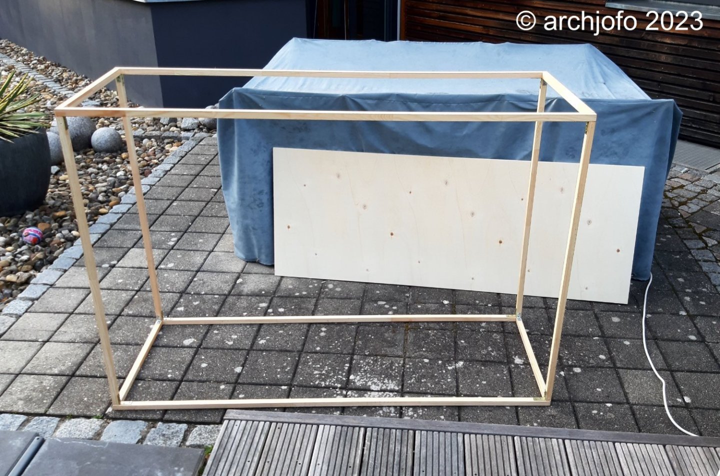
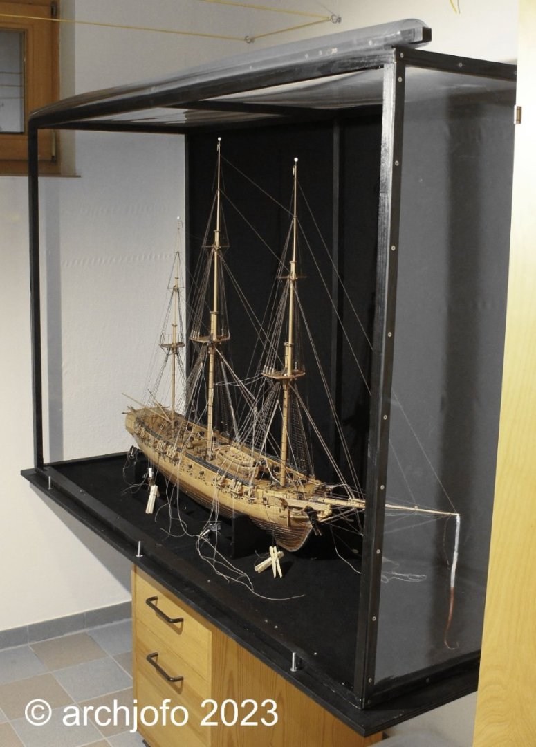
Making a dust cover Since the last post, very little has happened in my model building yard. If you are not working on the model, you don't have it in view all the time, so to speak, and therefore the first dust build-up cannot be counteracted, then it is advisable to place it under a protective cover. Since I will certainly be busy equipping the yards for some time, I have been thinking about protecting the model against dust for some time. A display case would be too impractical because you have to work on the model from time to time. In this respect, I thought about building a cheap dust cover that makes it possible to open the front in order to be able to remove the model or work on it. The frame was made with 20/20 mm spruce strips and metal angles and was covered with Molton fabric on the back. This ensures a neutral background and, if necessary, possible detailed shots. The remaining areas were covered with a crystal-clear PVC film. The front can be braced downwards using a longitudinal strip or rolled up at the top. Hopefully soon I will be able to pick up where I left off almost 2 months ago. So until then…


-
Hello, I am always deeply impressed by your clean and precise work. This results in fantastically beautiful details. I am a great admirer of your skills.
-
@giampieroricci @jose_b @druxey @jfhealey Hello, I am very pleased with your nice comments. That's an honor, but with a little patience and practice you can do it too. Of course I would also like to thank you for the many LIKES. Continuation: Equipment of the main topsail yard – brace blocks and lifts / Poulies de bras et balancines According to the table in the monograph, the blocks for the braces of the main topsail yard of the La Créole had a length of 190 mm in the original, which corresponds to a length of around 4 mm at a scale of 1:48. Like the brace blocks of the lower yards, these were attached to the yard ropes without rope swaps, but directly via thimbles (“Dog and Bitch” connection). The simple lifts were fitted over the yard arms with eye splices. Contrary to the arrangement of the footropes in the lower yards, in the topsail yards they are only placed further at the end of the yard arms. But more about that soon. I also have to clarify whether and how many stirrups were attached to the footropes of the topsail. There are no stirrups on the original Paris model, as far as I can tell from the images available to me. I still tend to be of the opinion that at least one stirrup per side wouldn't be wrong. Up soon …
-
@druxey Many thanks for the lovely comment and the reply. I would also like to thank everyone for the many LIKES. Continuation: Equipment of the main topsail yard - Jackstag, blocks for leech lines and bunt lines / Filière d`envergure, poulies de cargue de fond et poulies de boulin The topsail yards on the La Créole were also already equipped with jackstays. The two-piece and fully served jackstay for the main topsail yard was made in the same way as shown in the main yard and fore yard. The following picture shows part of the jackstay with the lanyard. On the next picture I show the blocks for the topsail yards again in size comparison (tye block of the main topsail yard, tye block of the fore topsail yard a bit smaller). Contrary to my sketch shown, the blocks for the braces are 4 mm long. In the meantime I have installed and lashed the jackstay on the main topsail yard and also lashed the blocks for the leech lines to it. So the lifts, the blocks for the braces and the footropes are still missing. I will also pull in the sheets and the clew lines as far as that. Sequel follows …
-
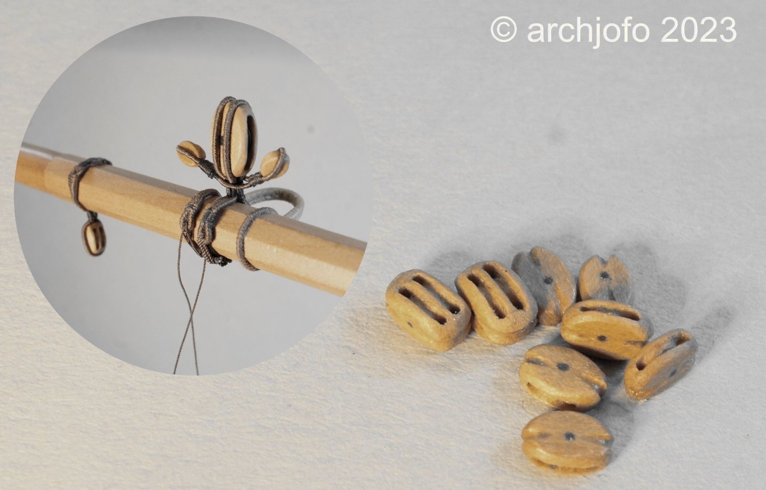
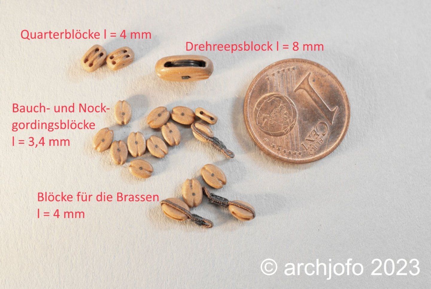
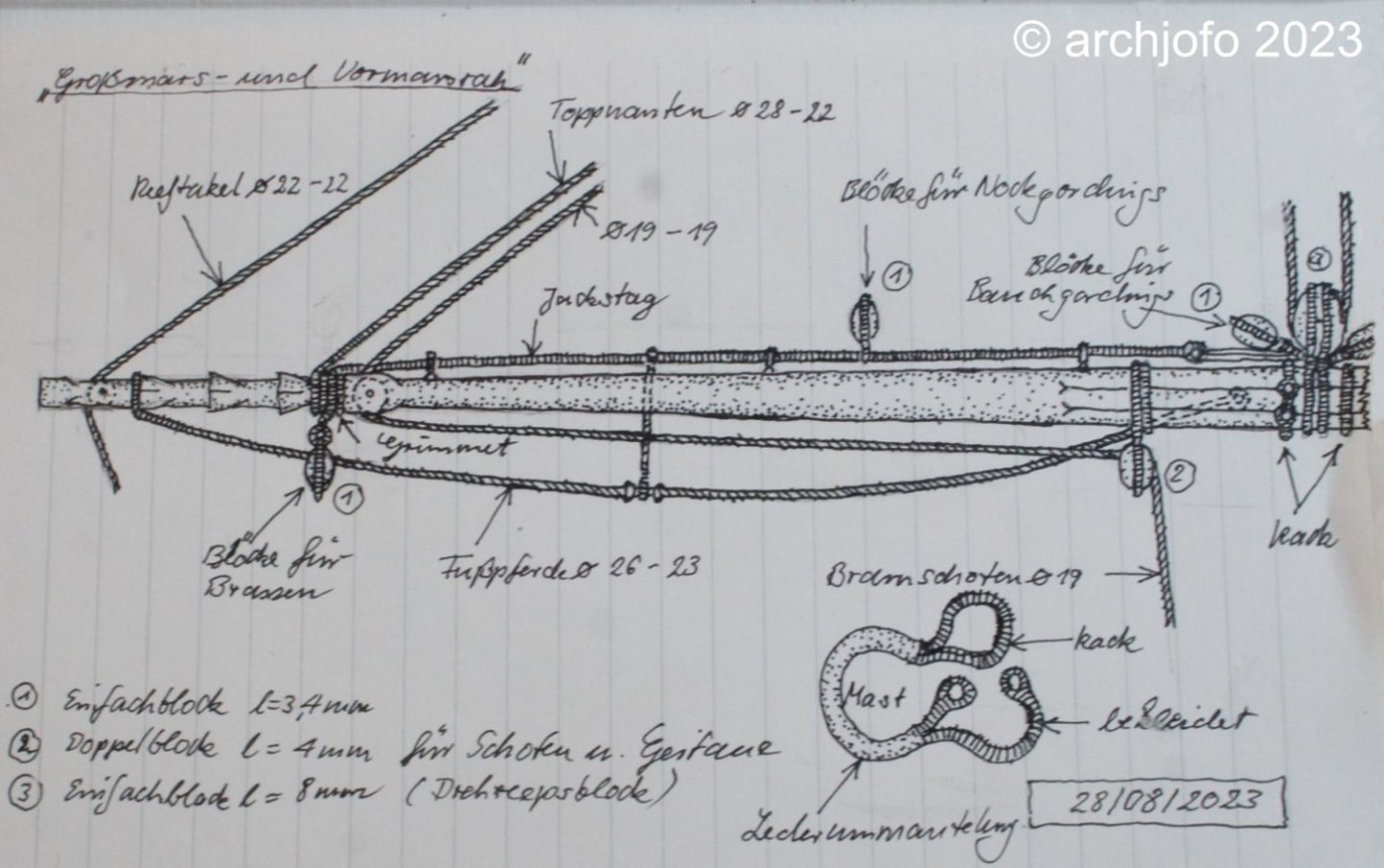
Continuation: Equipment of the topsail yards – blocks for bunt lines / poulies de cargue de fond Also mounted at the topsail yards were a number of blocks for the braces, leech lines and bunt lines. Due to the diameter of these ropes, the block sizes are 3,4 mm long. In order to be able to file the notches for the block strops better into the wood, I invested in a new needle file and equipped it with a nice handle made of service tree. Admittedly not exactly cheap, but this file has a diameter of only 1.0 mm at the top of the handle and tapers to 0.5 mm at the tip. Of course, there are other uses for this filigree tool. However, extremely careful handling of this filigree tool is required, as it can be damaged very easily. I equip the topsail yards according to the sketch below. In the meantime, further blocks for the topsail yards have been made. Among other things, the blocks for the bunt lines, which were already rigged to the main yard on the strop of the tye block, as can be seen in the next two pictures. Sequel follows …


-
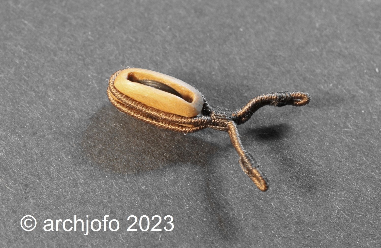
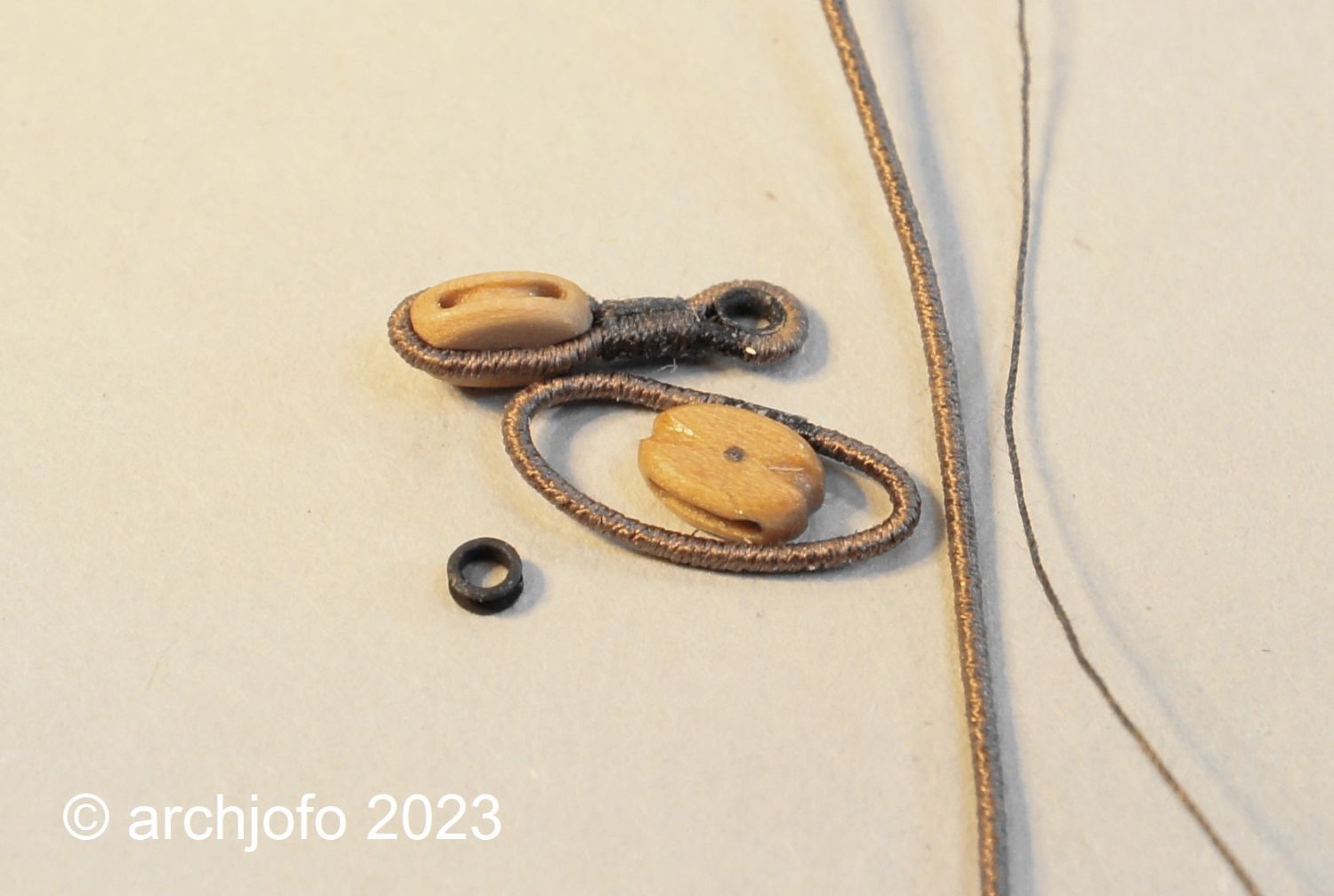
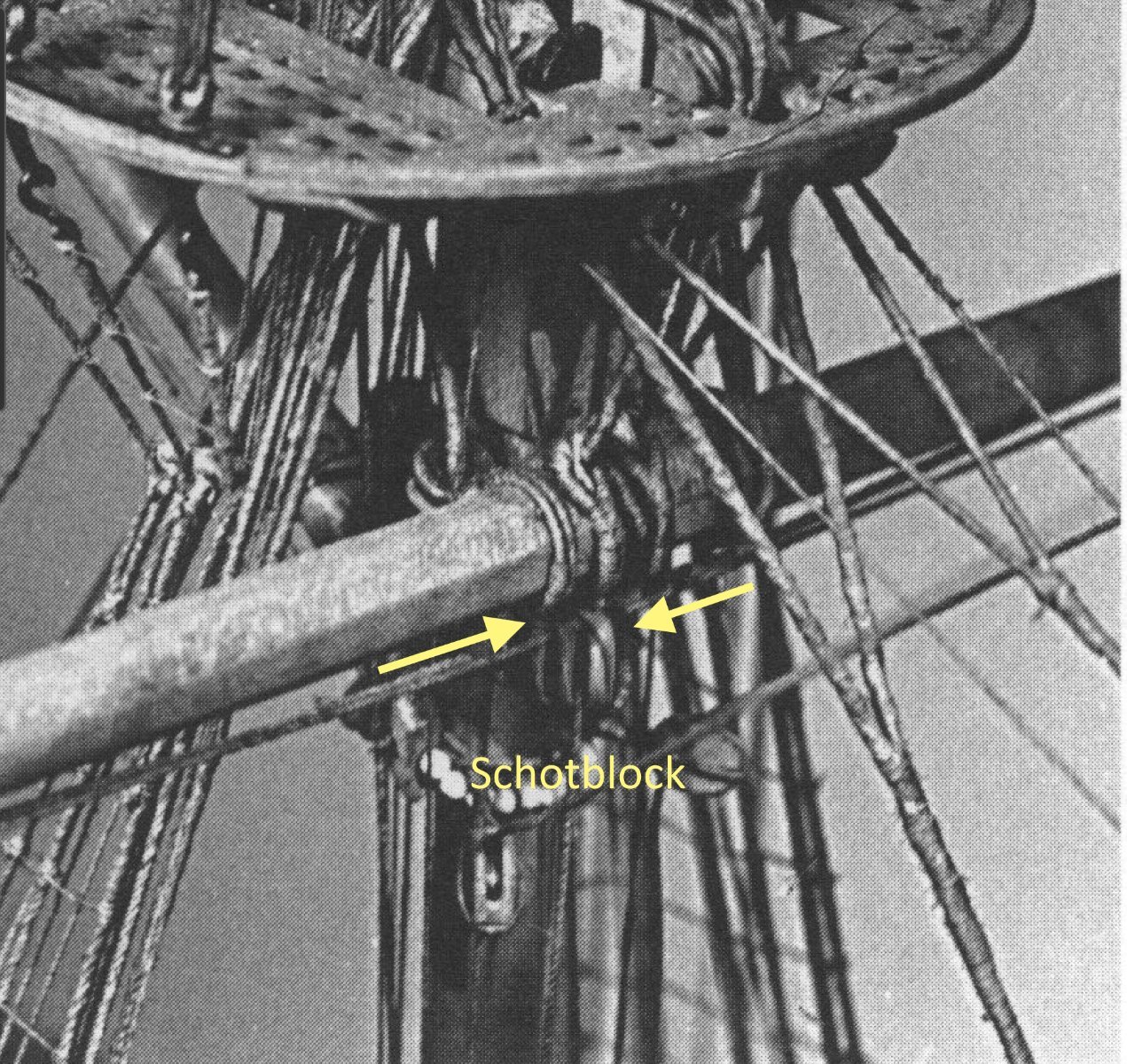
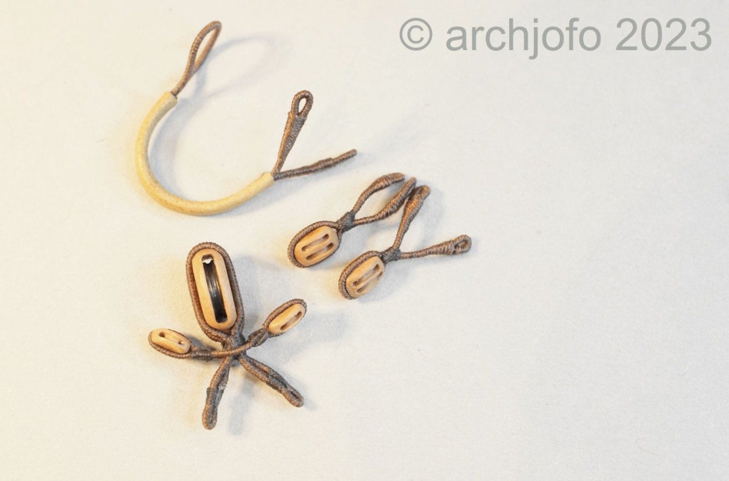
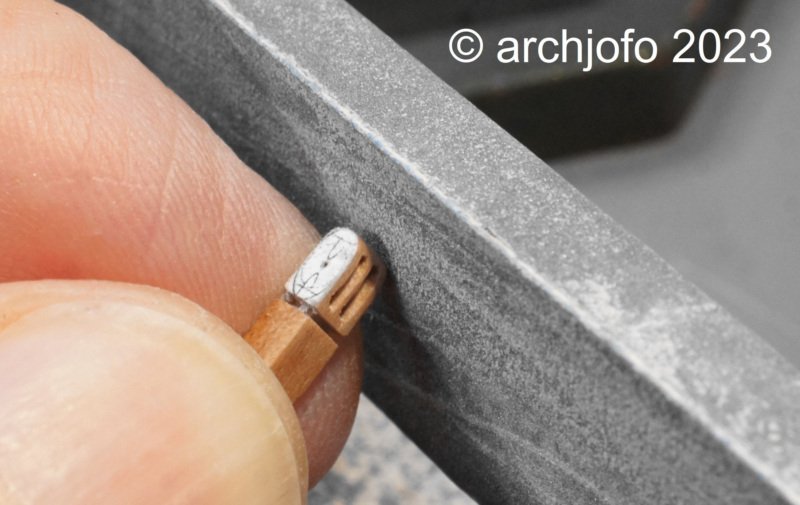
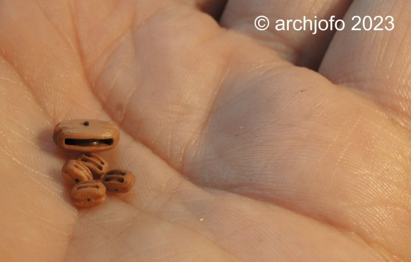
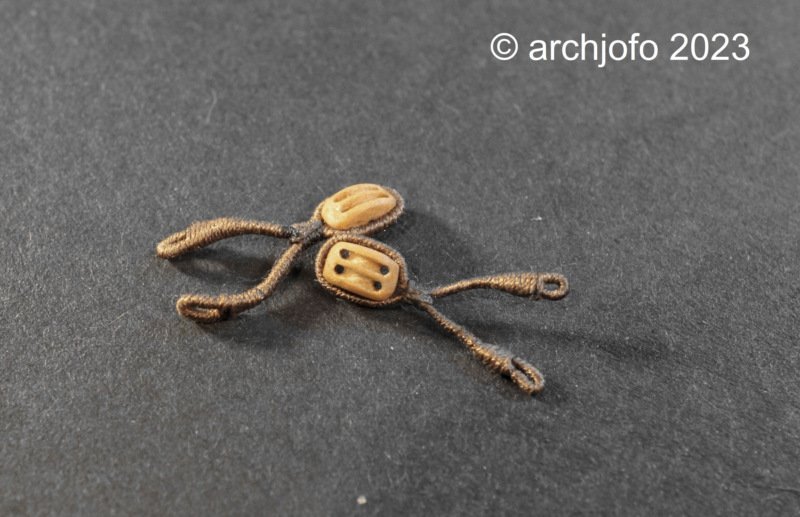
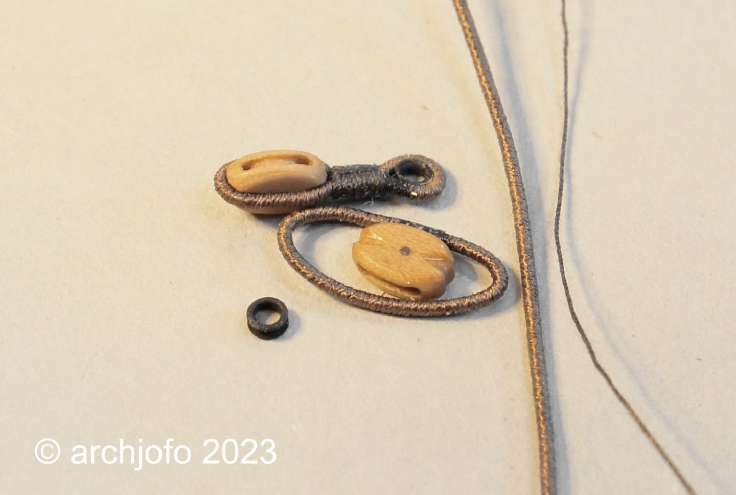
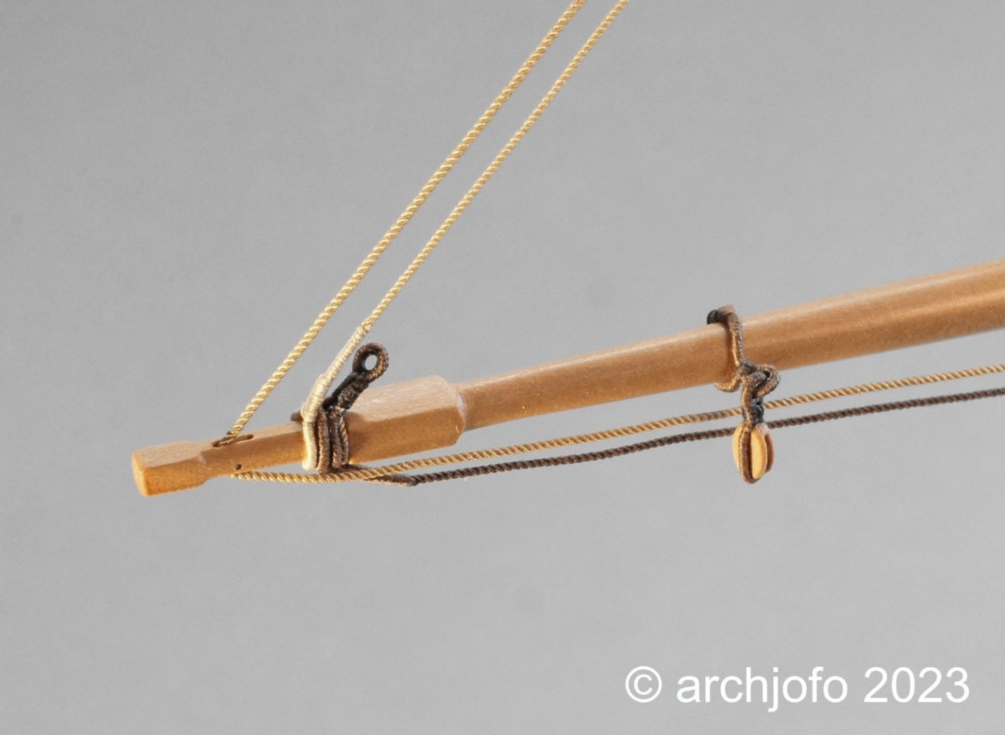
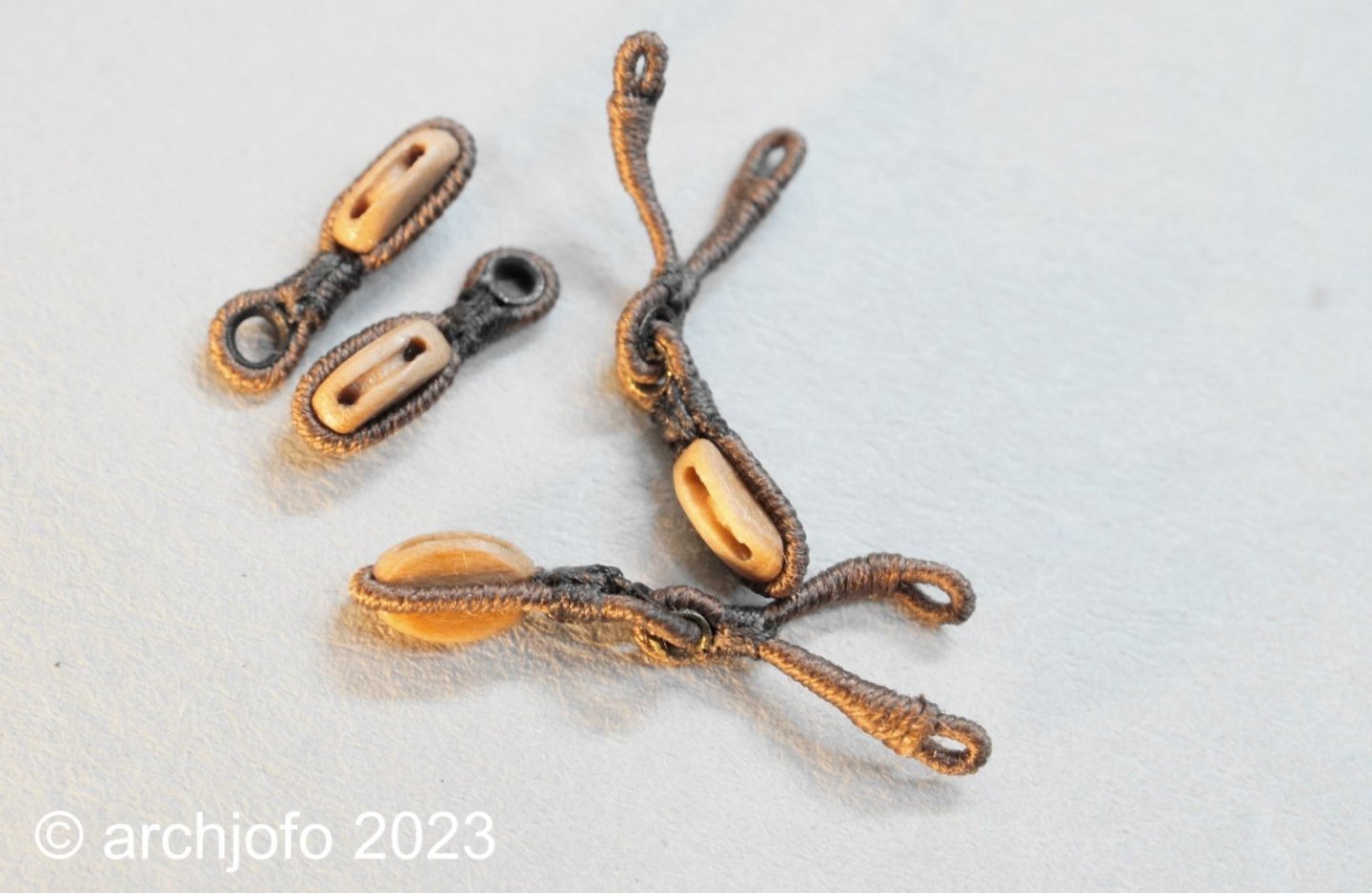
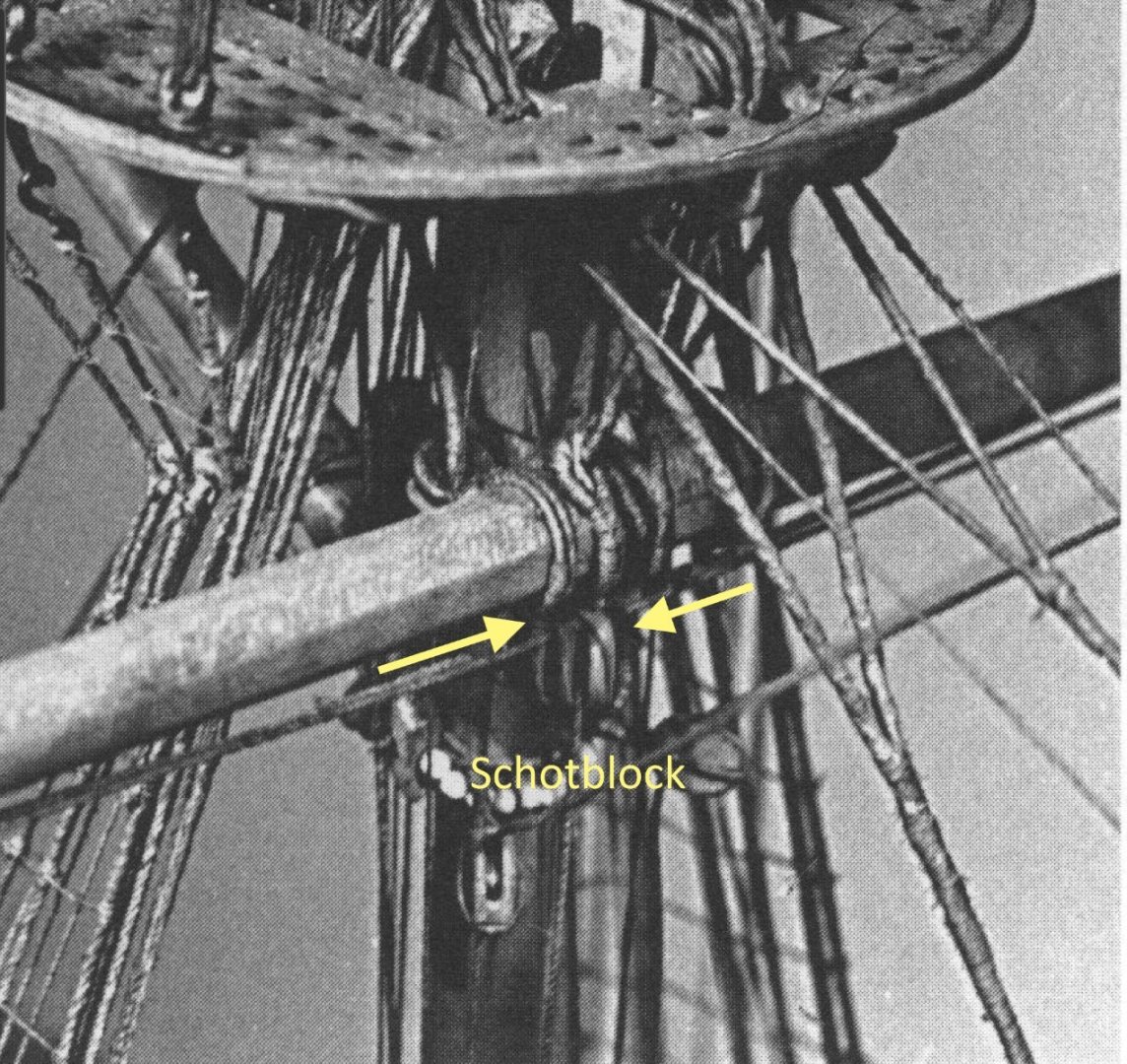
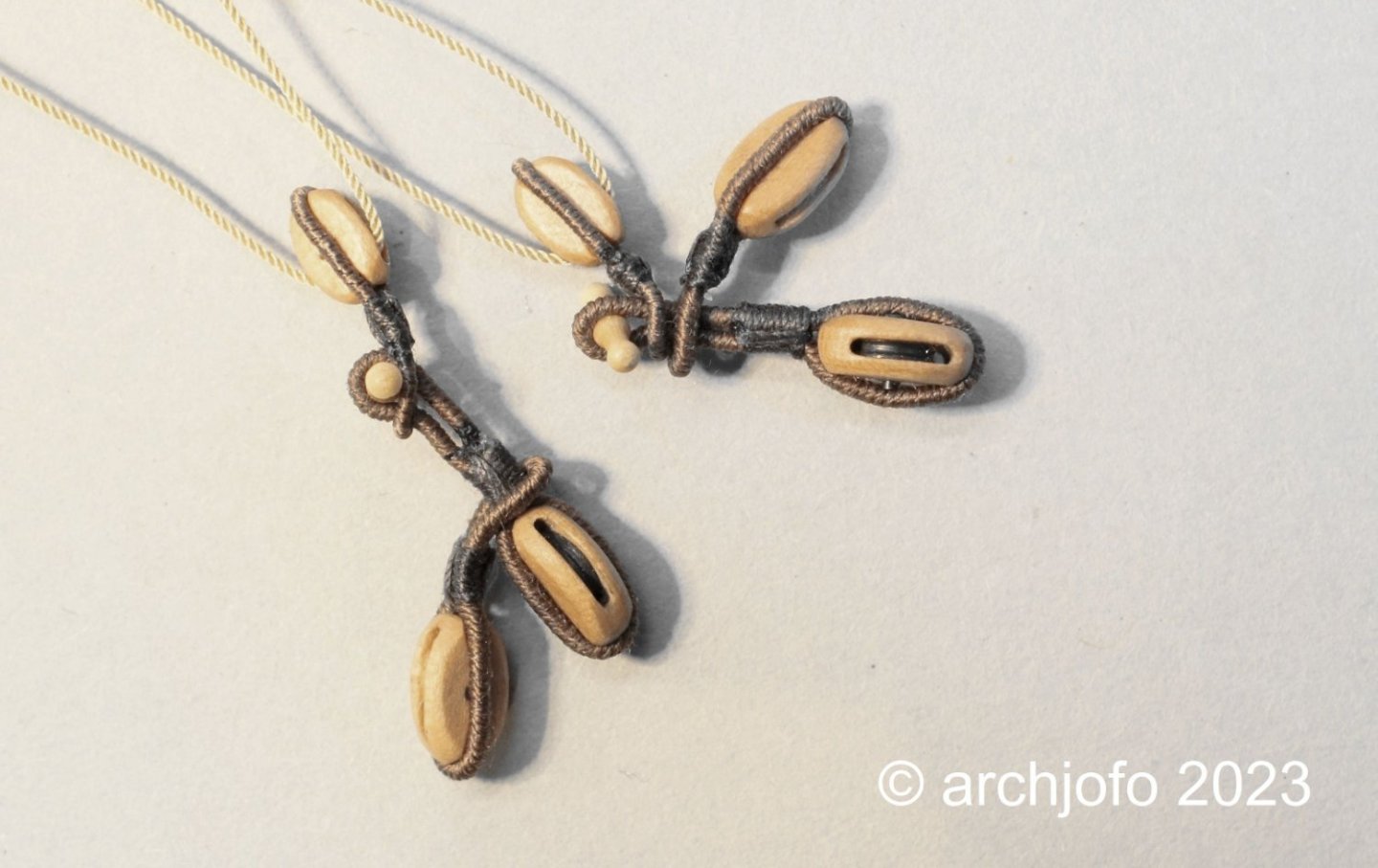
Continuation: Equipment of the topsail yards - quarter blocks / poulies d'ecoute et poulies de cargue de point The quarter blocks, usually two-disk blocks, were also referred to as thick-and-thin blocks by the English. The sheaves for the topgallant sheets were thicker and the clew lines ran over the thinner sheaves. The lower yards used separate single sheave blocks for the sheets and clew lines. For my model of the French corvette, I made the 4 mm long double blocks using the method already described several times. Since the main topgallant sheets and the fore topgallant sheets with ø 19 mm and ø 17 mm do not show a big difference, the difference in thickness of the block disks is only marginal. With the block strops, the first attempt seemed too out of scale (on the left in the picture). I found the second attempt with thinner strops much more appropriate. The last two images show the lashed quarter blocks in position. I haven't gotten any further with the research into the execution of the reef tackles. You may have information on what the French looked like. See you then …

-
Hello Greg, thanks for the tip.
-
@jdbondy Hello JD, yes, it is very thin goatskin. I split that myself with a simple jig to a thickness of about 0.2mm. Many parts of the rigging were formerly covered with leather. In my construction report I have already described parts of the rigging with leather at the appropriate places. If you are interested, you can read more here: LINK
-
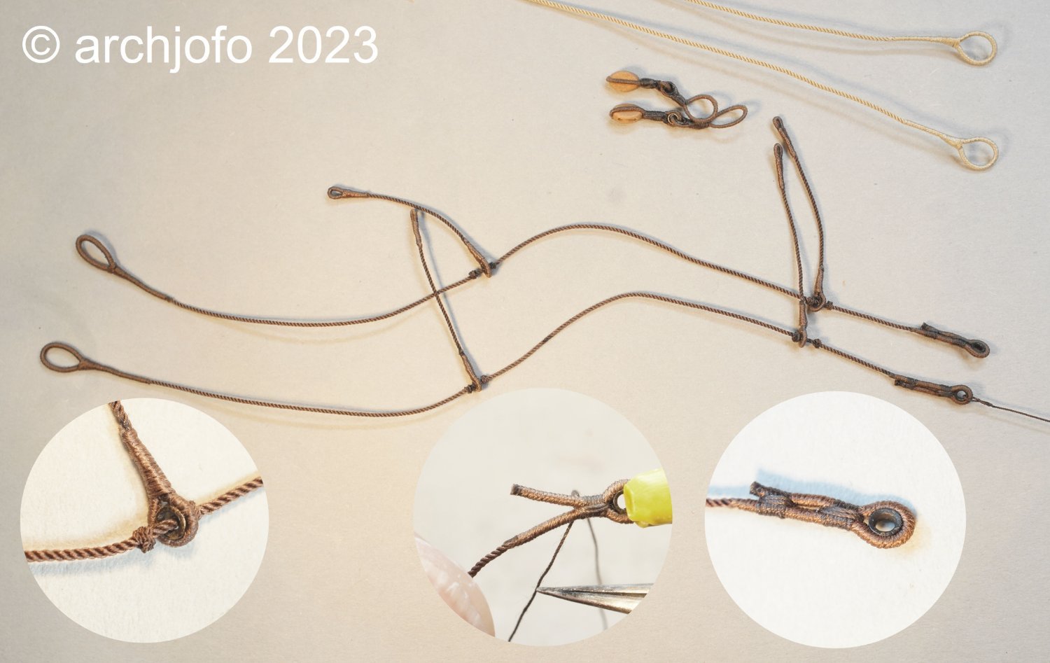
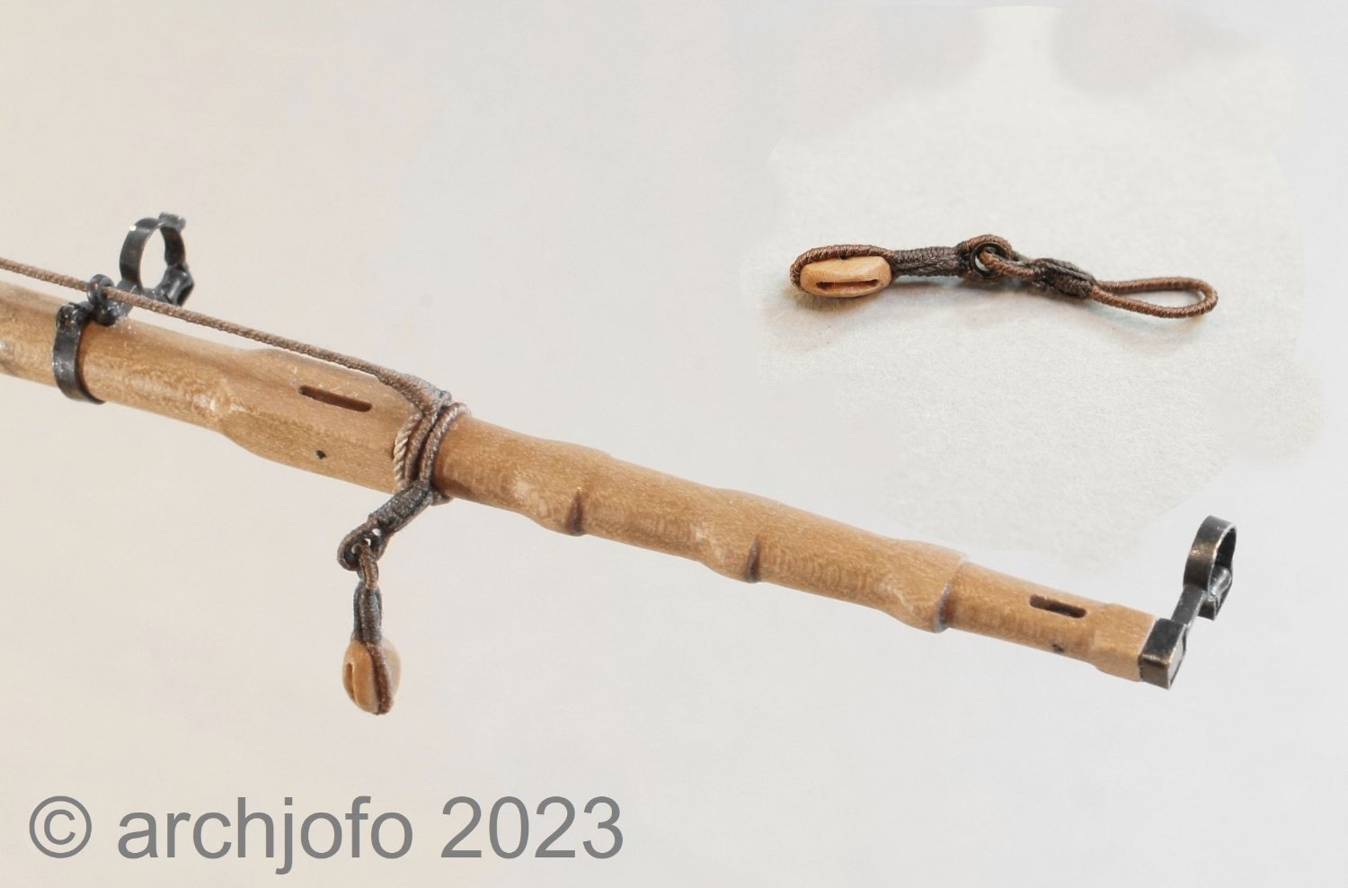
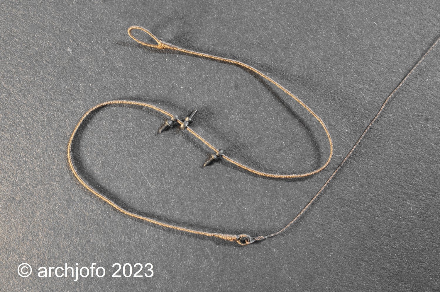
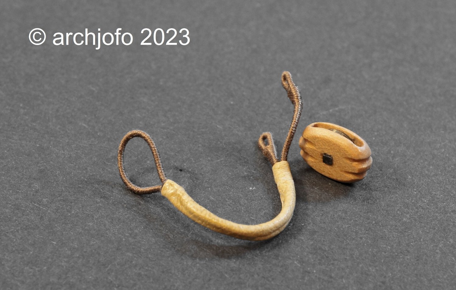
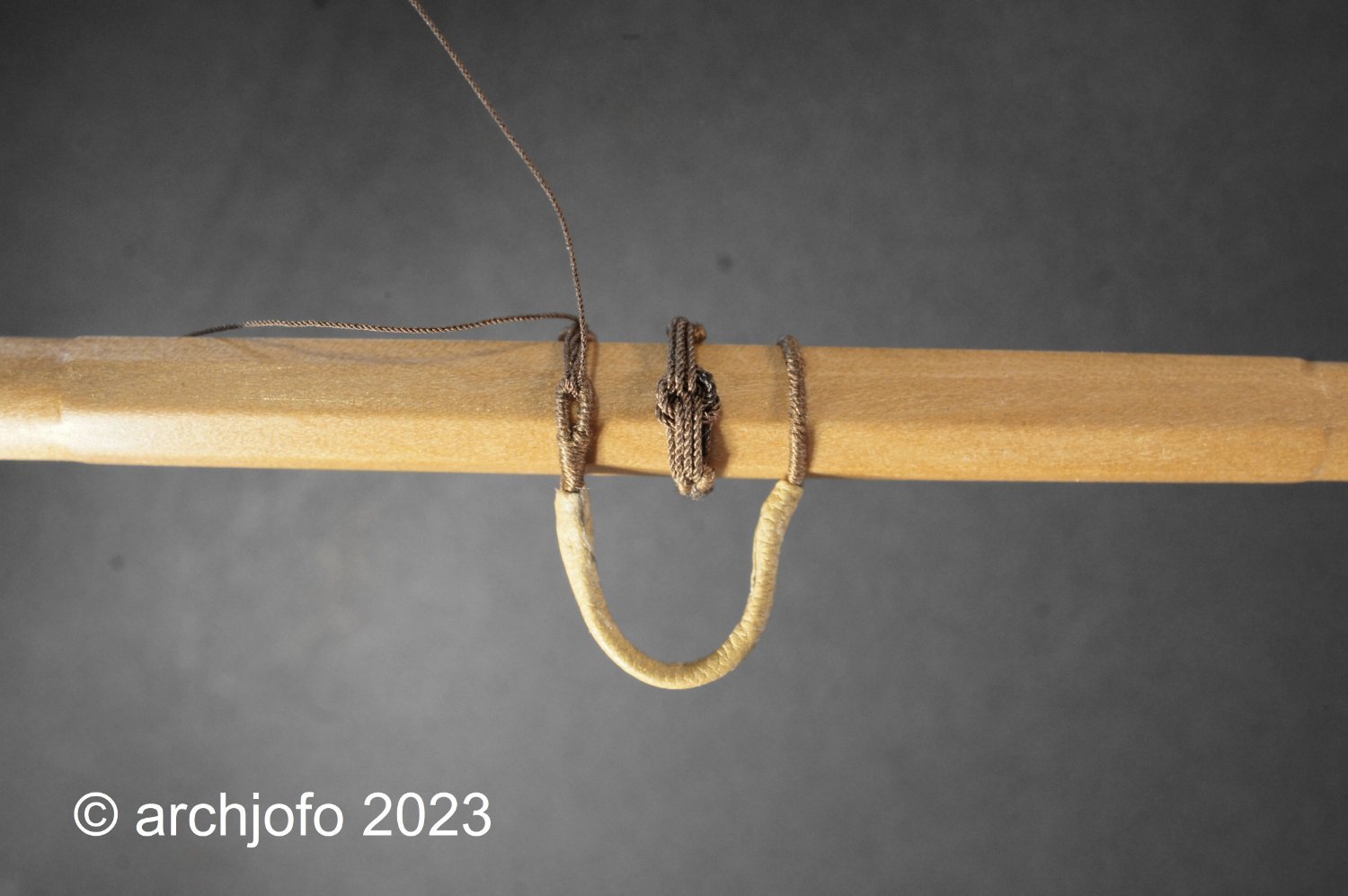
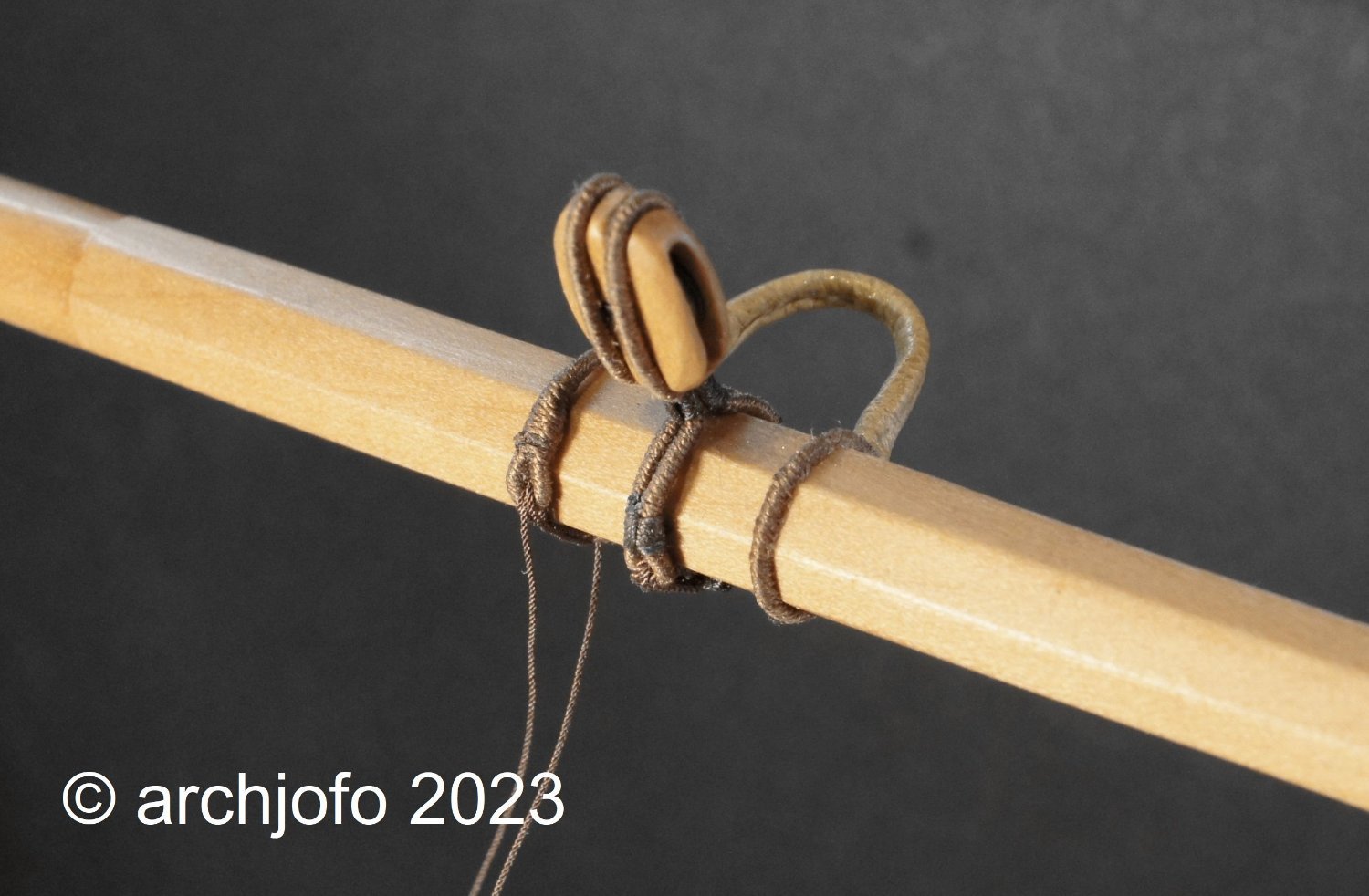
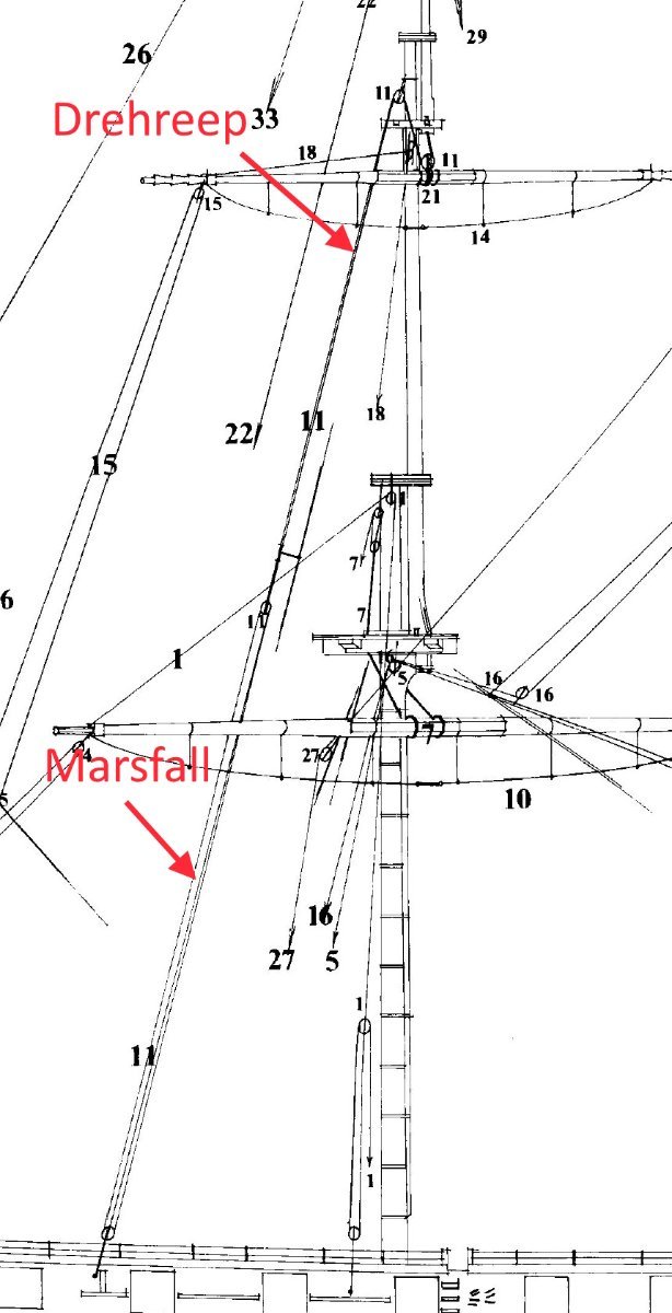
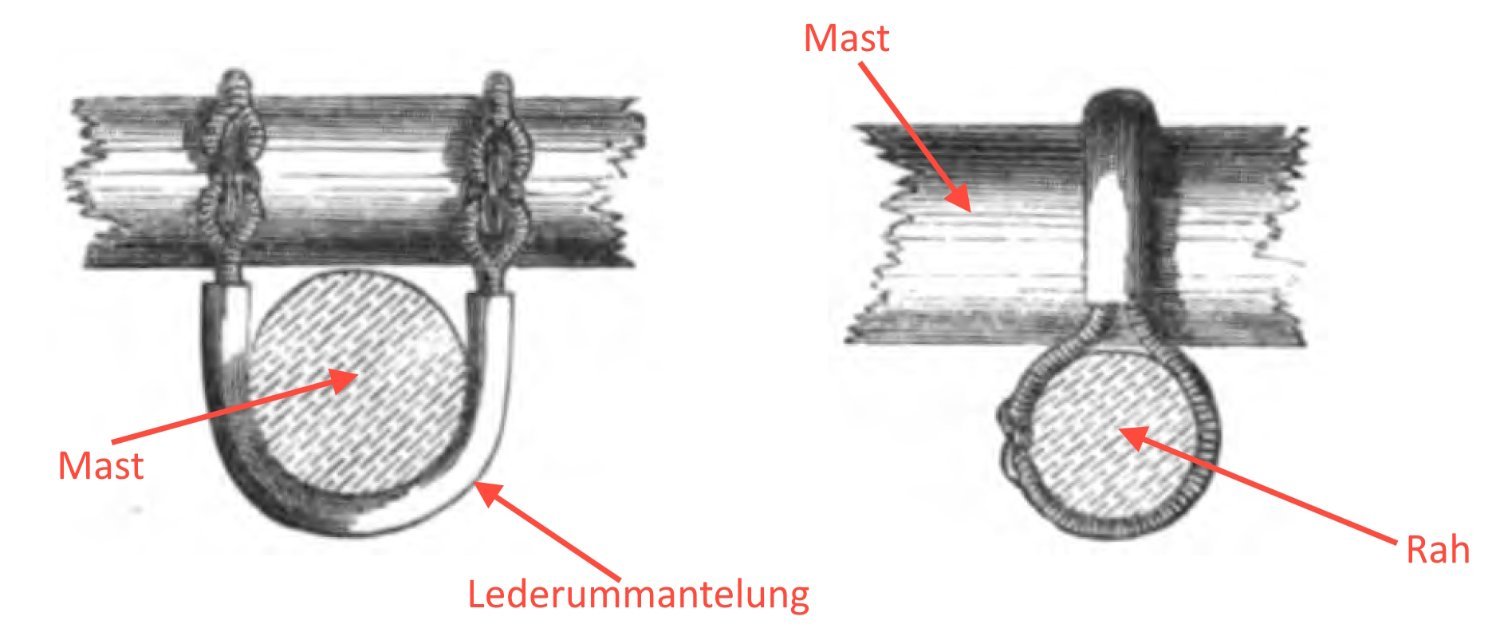
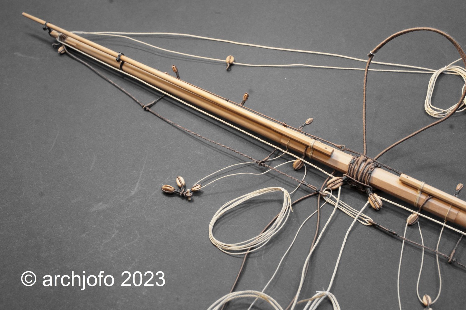
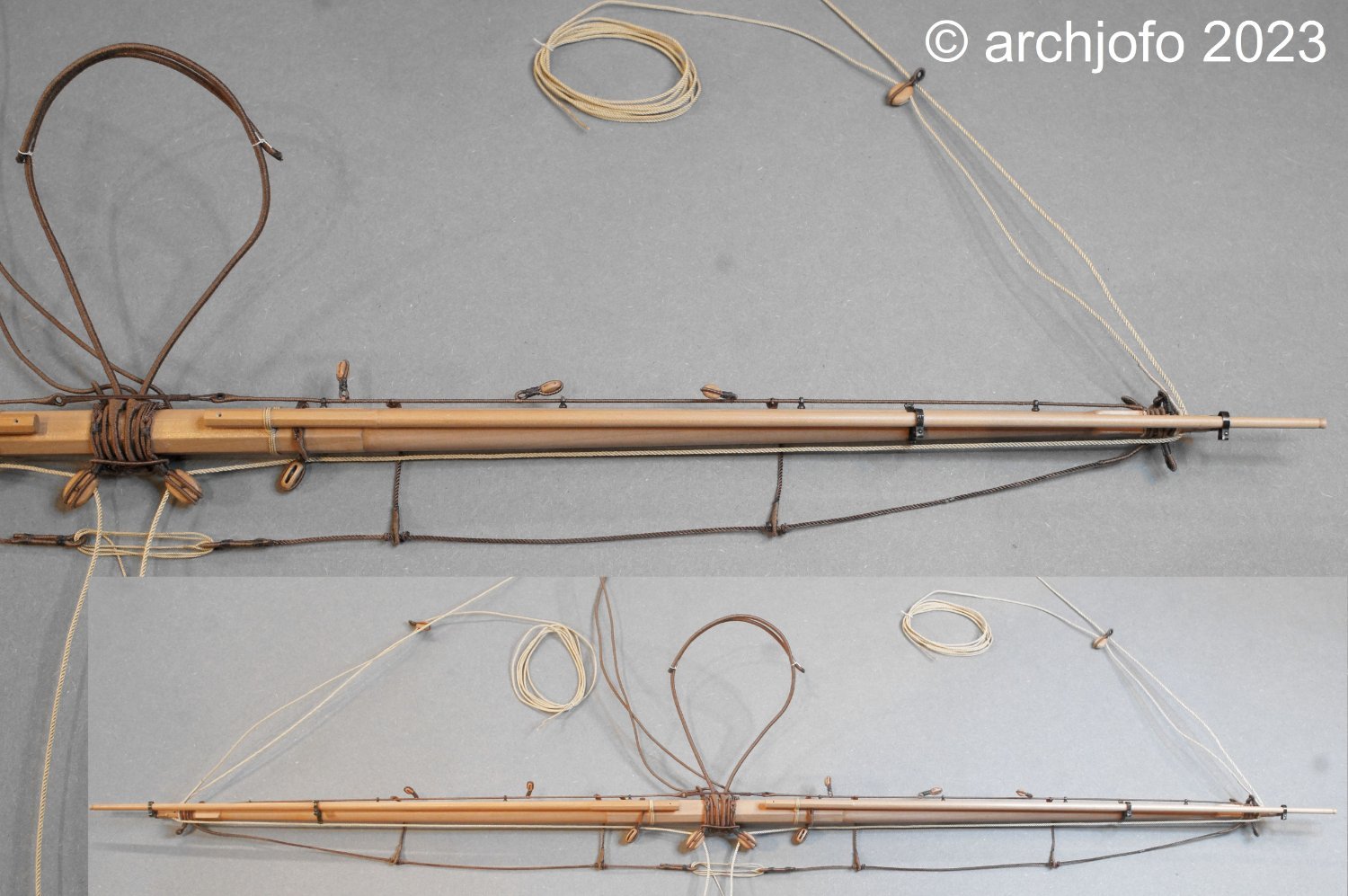
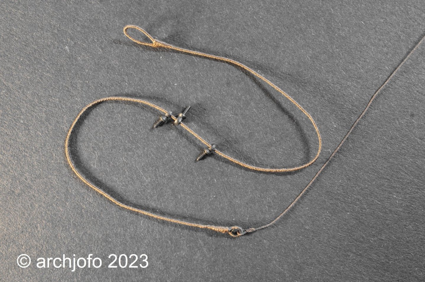
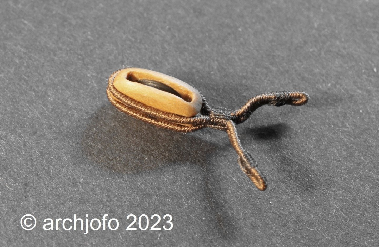
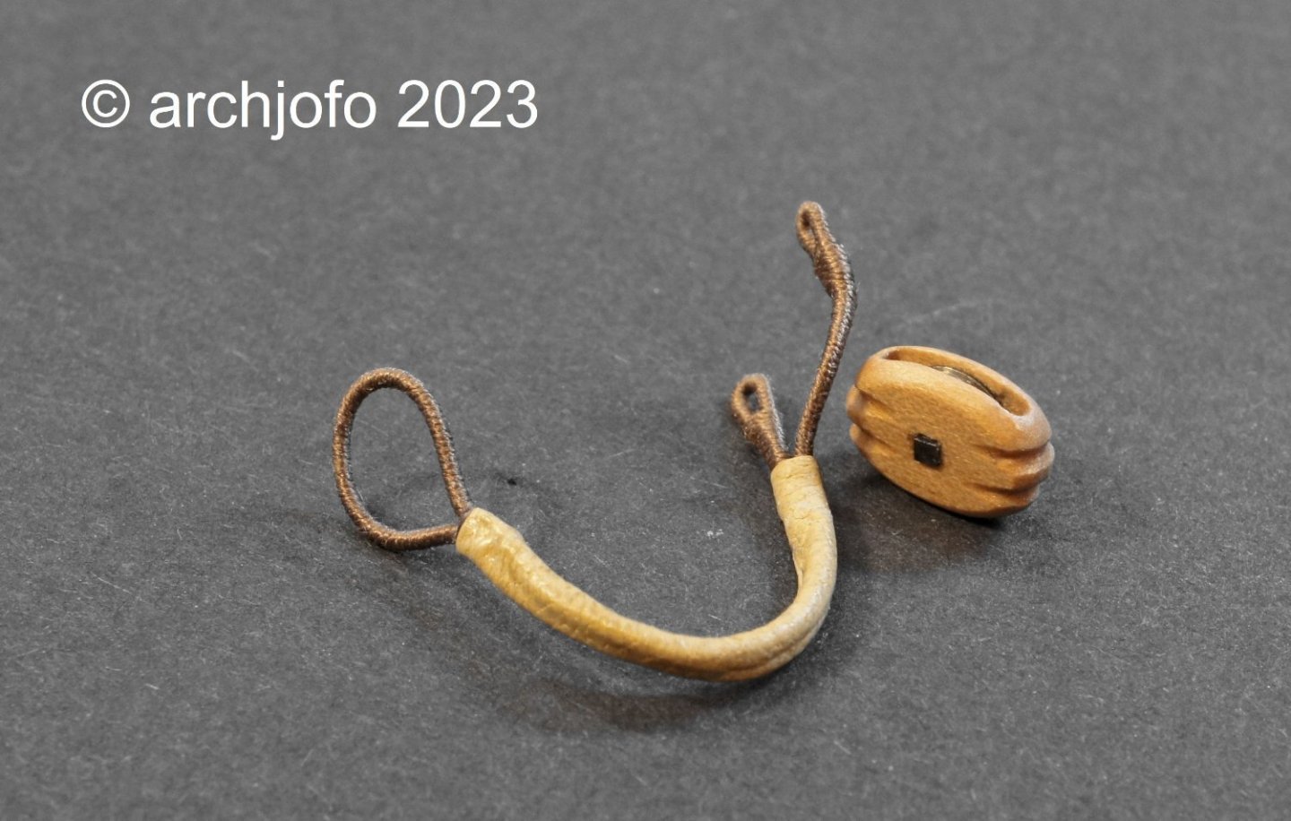
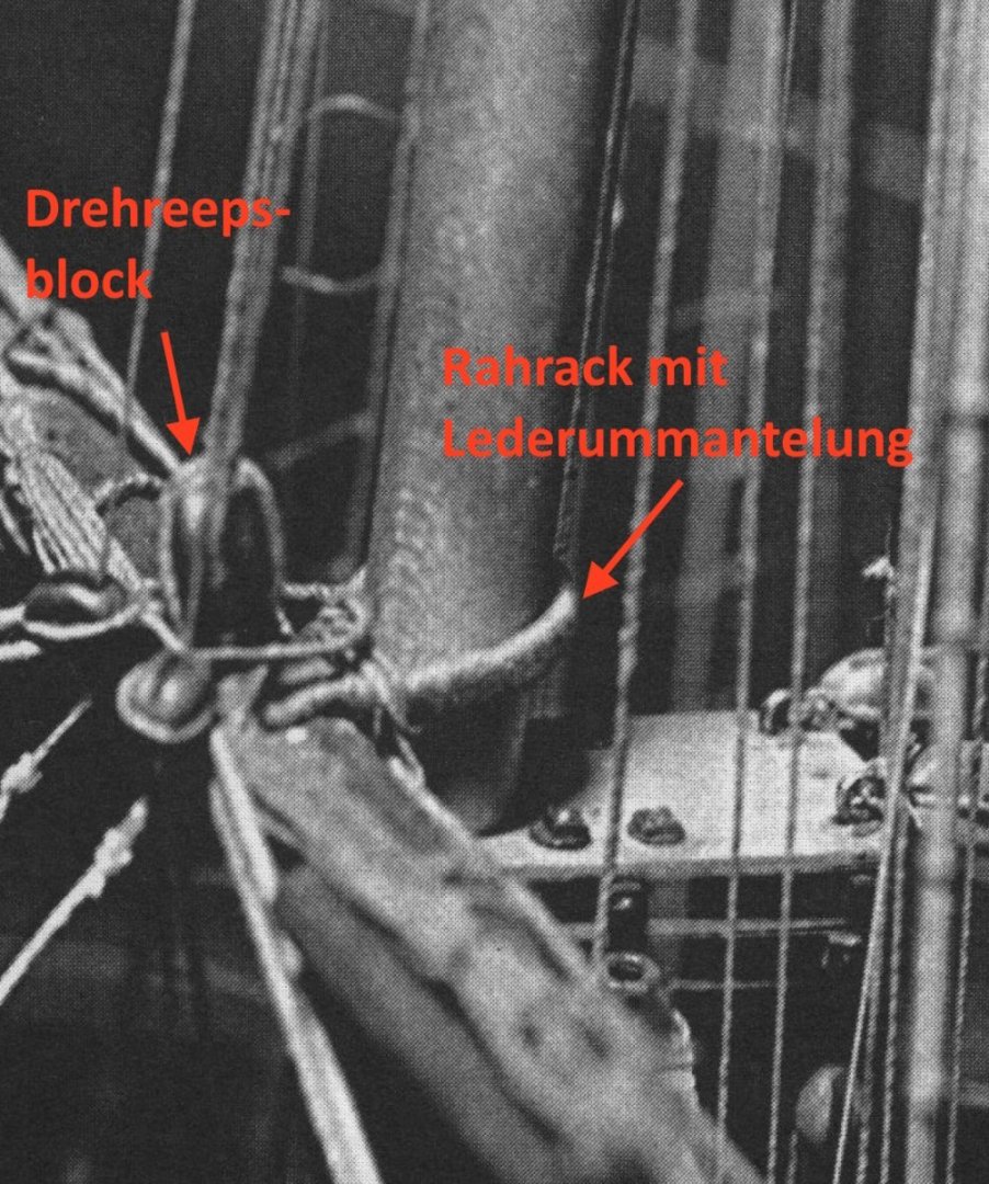
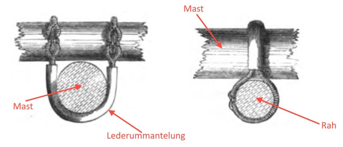
Equipment of the Topsail yards - topsail yard parral and topsail yard tye / Racage d´une vergue et poulie d´itague The rigging of the topsail yard differs from the lower yards in particular in the following peculiarities: Reef tackles, parrals and tyes with halyards. The parrels of the topsail yards had the task of holding the yard firmly to the topmast, but at the same time there had to be enough play to allow the yard to catch sharply. In addition, the parrel should ensure that the yard can slide up and down the spar. The parrals of the topsail yards were less complex than those of the lower yards and therefore not adjustable. When the La Créole was fitted out, parrals with ribs and trucks gradually went out of fashion. As already mentioned several times, this corvette already had many "modern" equipment elements, not only in the rigging. According to the description in the monograph by J. Boudriot in connection with the following image section from the original Paris model, it is clearly expressed that this was a pure parral, without ribs and trucks. The rear area around the topmast was protected against wear and tear with a leather cover. Source: Monograph La Créole by Jean Boudriot, page 169 I derived the further detailed design for my model as shown below from Seamanship by G. S. Nares, with the difference that a closed eye was formed on one side. This is evident from the description in the monograph. Source: Seamanship, G.S. Nares, 1868 This corvette passed double tyes for hoisting and easing topsail yards. The tye blocks at La Créole were three large blocks. The tye then goes through the one block in the middle of the yard and through each of the blocks placed under the cross trees of the topmast head. At the end of the tyes, the blocks of the halyards were integrated, which were fixed to the channels. Source: La Créole monograph by Jean Boudriot The following pictures show the implementation of this rigging element for the main topsail yard: For the further rigging of the main topsail yard I still have to clarify various details, such as B. reef tackles, jackstays, blocks for sheets, clew lines, bunt lines and leech lines. Sequel follows …


-
Fantastic work !
-
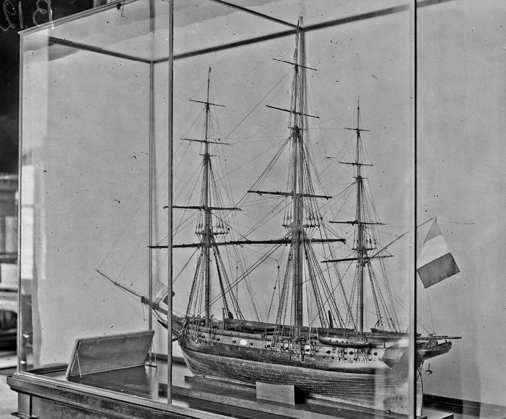
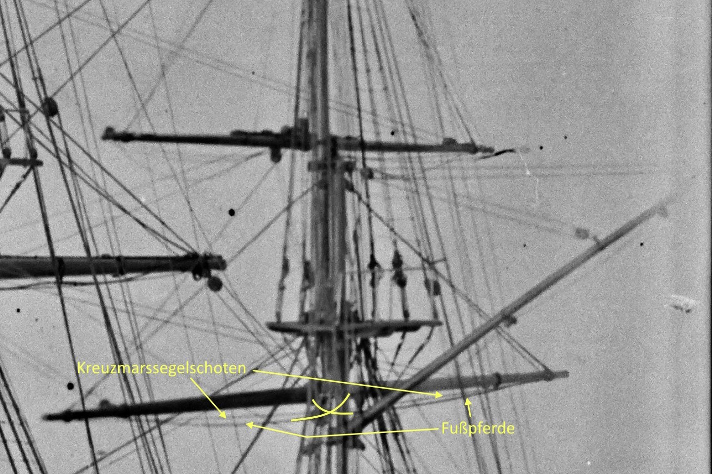
Completion: Equipment of the mizzen yard - footroopes, mizzen topsail sheets, lifts etc. / Marchepieds, ècoutes de perroquet de fougue, balancines etc. Based on an older photo of the Paris model of the La Créole, I was able to trace the execution of the footropes for the mizzen yard as far as possible (see picture detail). Source: Gallica, Bibliothèque nationale de France, Corvette La Créole [modèle réduit de bateau exposé au musée de la Marine, au Louvre] : [photographie de presse] / [Agence Rol] 1904-1908 Source: Gallica, Bibliothèque nationale de France, Corvette La Créole [modèle réduit de bateau exposé au musée de la Marine, au Louvre] : [photographie de presse] / [Agence Rol] 1904-1908 - detail of picture The corresponding size of the mizzen yard of a corvette obviously did not require stirrups in the footropes, as can be seen in the above image detail. In this respect, I based the execution of my model on this specification. In front of the footropes, the grommets, the strops with thimble and finally the lifts were attached to the yardarms of the mizzen yard of the model. The next picture shows details of the 4 mm long blocks of the lifts, which will later be attached to the top of the mizzen mast on corresponding eyebolts. The next picture shows a yardarm with the previously mentioned rigging elements and the already retracted mizzen topsail sheets. And finally two more pictures of the finished rigged mizzen yard: See you soon ...


-
Brig Le FAVORI 1806 by KORTES - 1:55
archjofo replied to KORTES's topic in - Build logs for subjects built 1801 - 1850
This is absolutely admirable clean work. This will be a fantastically beautiful model. -
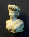
Equipment of the mizzen yard– truss pendant and brace blocks/ Drosse d´une basse vergue et poulies du bras de artimon The mizzen yard is also attached to the mast with a truss pendant, analogous to the fore yard and main yard. The diameter of the ropes are of course much smaller. Of course, the braces for the mizzen yard can only be moved forward. The standing parts were fixed to the aft shrouds of the main mast. Through another block, which was also attached to the shrouds, they ran down to the docking stations on deck. Because of the backstays of the mainmast, the blocks of the braces on the mizzen yard had to be placed closer to the middle of the yard. On the following picture collage, picture 1 shows the blocks of the braces (l = 4.0 mm), partially strapped, for the mizzen yard. To do this, I placed two sheet blocks of the main yard to enable a size comparison. Image 2 shows a fully strapped block of the braces and another unstraped one compared to a brace block of the fore yard. My little sailor, which I've been neglecting a bit lately, is supposed to give you a feeling for the scale of the block sizes. The next picture shows the finished blocks for the braces. On the one hand, which are installed directly on the yard, and on the other hand the deflection blocks, which are attached to the rear shrouds of the mainmast. As I read in C. Burney's The Boy's Manual of Seamanship and Gunnery, 1867, rose lashing was the standard connection of strops around yards and masts. Therefore, a rose lashing makes sense to me here. Finally, there is a picture with a brace block already installed. Soon we will continue with the foot ropes for this yard. Or were foot ropes necessary in this case? Sequel follows …


-
@Blacky Hello, Greg @dvm27 has already answered it so far, for which I'm grateful. I look up a lot in the Ashley Book of Knots, which Bob @Bob Cleek also pointed out. In some you have to simplify things in order to be able to implement them at model scale. I only partially know the other sources mentioned by Bob. Thanks for that too.
-
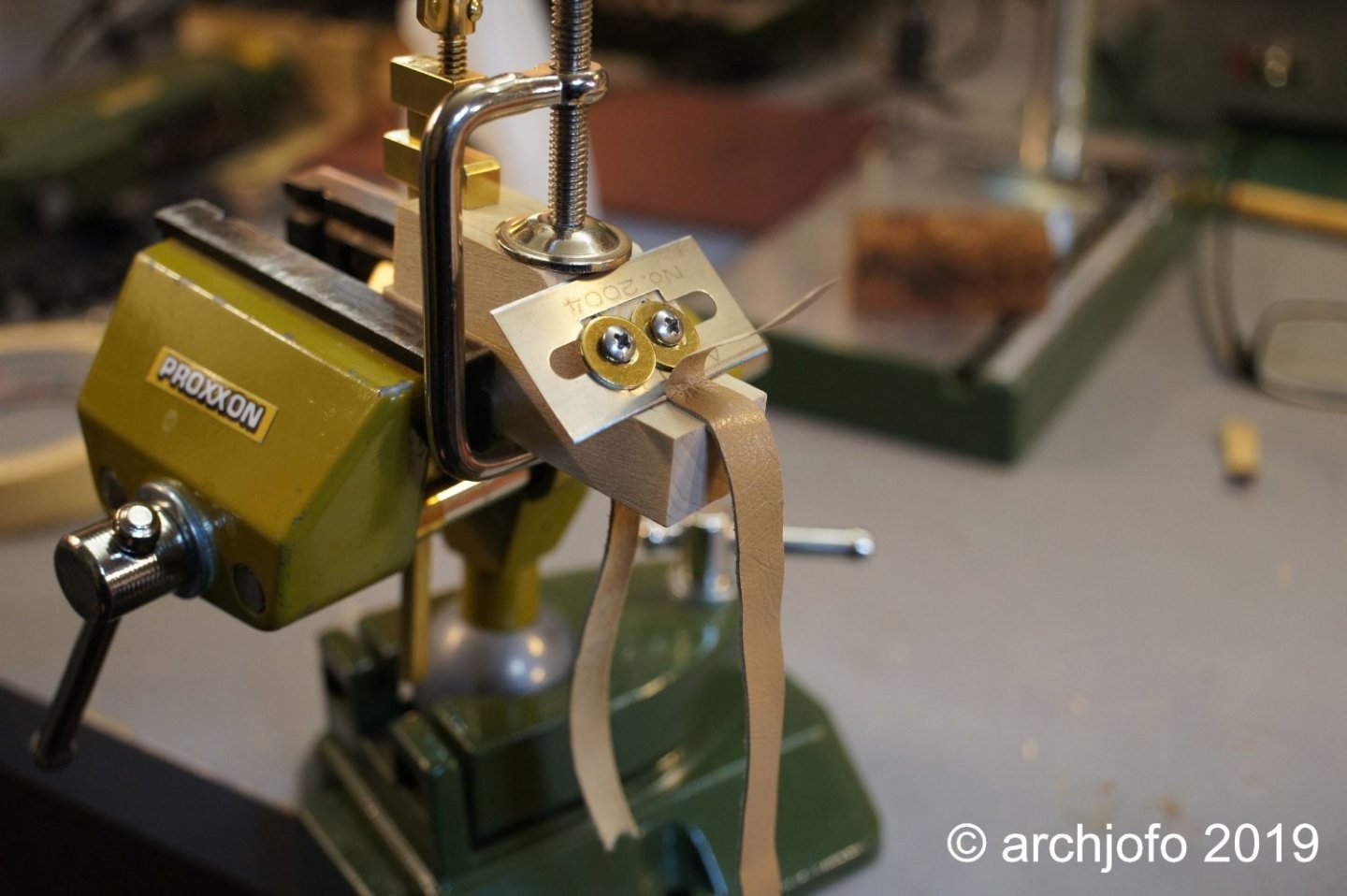
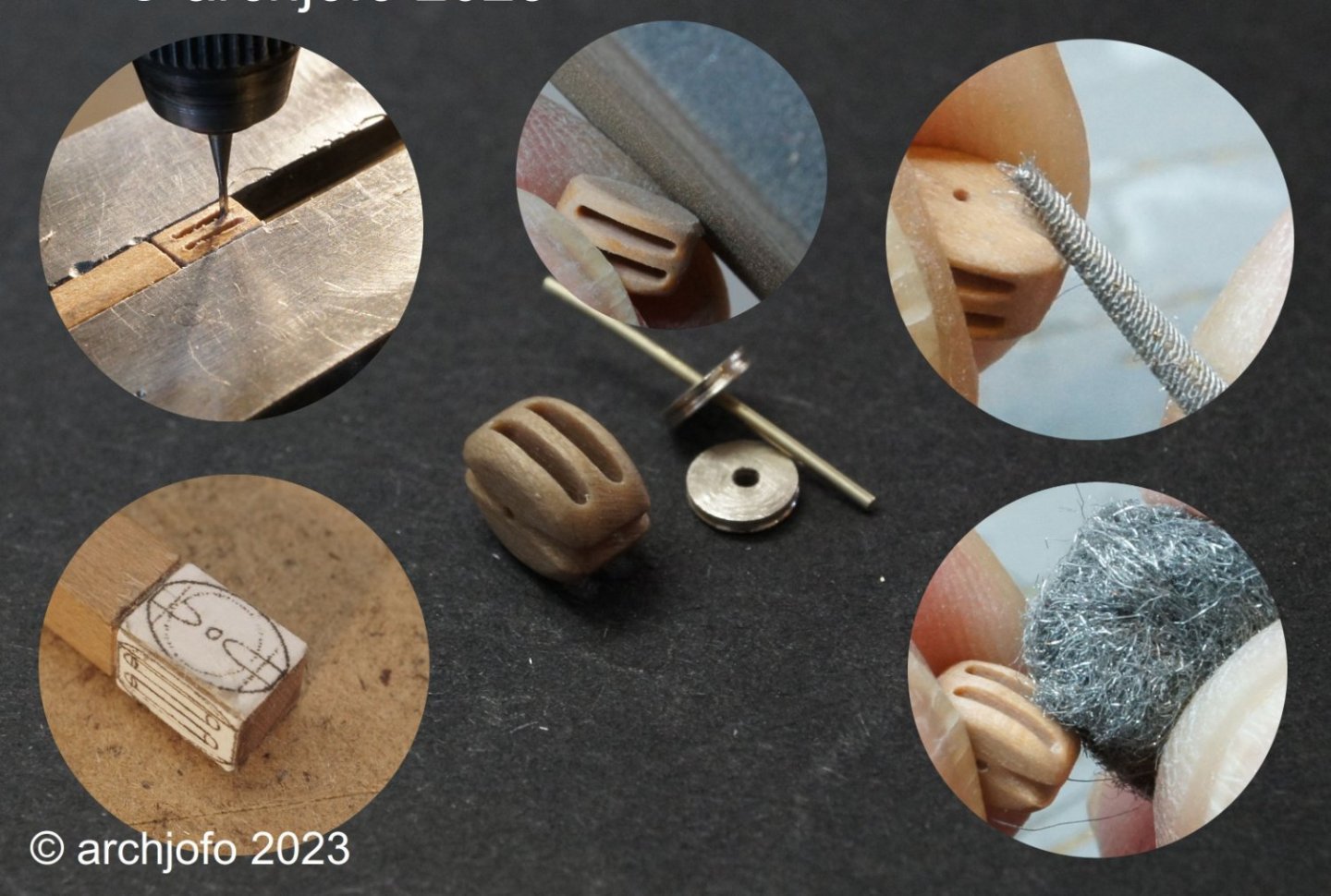
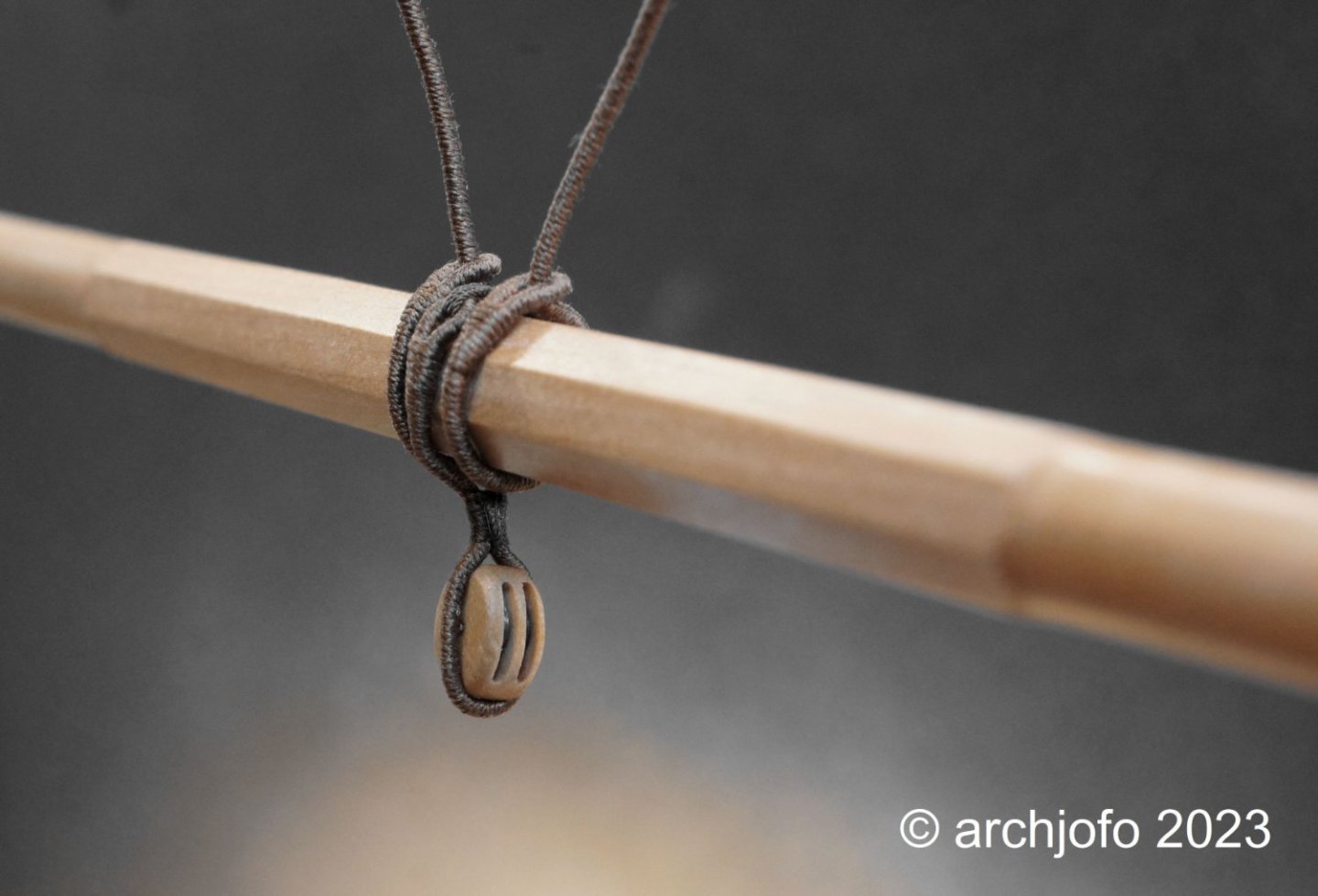
Equipment of the mizzen yard - Slings and Quarterblock / Suspentes et poulie d'ecoute The mizzen yard of the La Créole had no jackstay and only a quarter block for deflecting the sheets in the middle of the yard. This block was therefore designed as a double block, as can be seen in the following detailed photo of the Paris model. Source: La Créole monograph by J. Boudriot, page 168 Based on these double blocks with a length of 5.6 mm in model size, I would like to explain my method of block production in more detail. I scale the drawing of a double block from the Atlas du génie maritime to the required size and glue the printout to a strip of pear wood with the appropriate dimensions. Since I use separate discs for this block size, the disc gates are milled in the next step. In this case with a width of 0.6 mm. After shaping with an emery file, the grooves for the strops are made with a round file. The fine sanding is done with a fine steel wool and the final finish is done with a ball matting. As can be seen in the next picture, I have meanwhile attached the fully served slings and in between the double block for the mizzen topsail sheets using rose lashings. The next step will be the production of the truss pendants. Sequel follows …

-
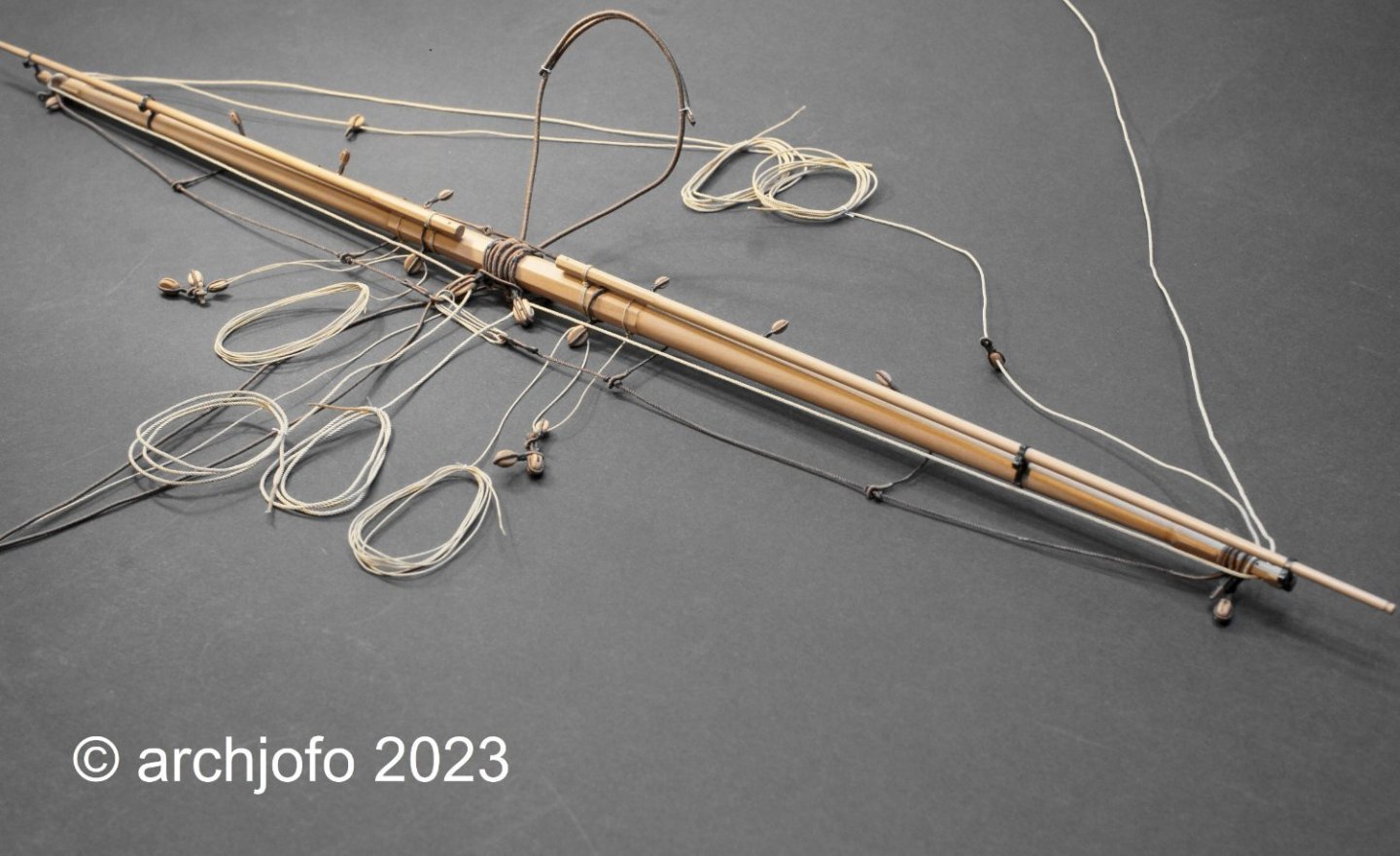
Completion: Equipment of the fore yard With the production and arrangement of the blocks for the clewlines, sheets and tacks, the fore yard is fully equipped and is set aside until assembly on the model. At the end of this work on the fore yard, here are a few more pictures: The last of the lower yards that still needs to be equipped is the mizzen yard. Sequel follows …

-
@JerryTodd Thank you for your praise. Nice to hear. Continued: Equipment of the fore yard - topsail sheets, lifts and studding sail booms In the meantime, the topsail sheets, the lifts and the studding sail booms were attached to the fore yard for my little French girl. I almost forgot an important detail to complete the equipment of the fore yard, namely the arrangement of the blocks for the clewlines, the sheets and the tacks. I'll do that again and report back soon. So see you soon...