HOLIDAY DONATION DRIVE - SUPPORT MSW - DO YOUR PART TO KEEP THIS GREAT FORUM GOING! (89 donations so far out of 49,000 members - C'mon guys!)
×

archjofo
-
Posts
1,498 -
Joined
-
Last visited
Content Type
Profiles
Forums
Gallery
Events
Everything posted by archjofo
-
 @shipman @SaltyScot Hello, Thank you very much for the nice comments. I'm very happy. Thanks also to everyone else for the many likes. Continuation: Fore yard – Bowlines / Boulines I've also since read up on the arrangement of the bowline bridles in the contemporary specialist literature "Manuel de Greement" by F. A. Coste from 1829, starting on page 167, and it fits. The only thing is that it refers to thimbles through which the individual rope limbs are threaded. I also looked again in Marquardt, which also covers the rigging of French ships, although again only up to the end of the 18th century. If I now incorporate the aforementioned contemporary illustrations from the early 19th century and models from the Paris Museum into my considerations, I come to the conclusion that the bowline bridles on my corvette could well have looked the way I have since attached them to the fore yard. I can't clearly verify the attachment of the bowlines without sails for the French, as shown in the K. Schrage's book – Rundhölzer, Tauwerk und Segel – . But I think it's quite realistic that the French did it the same way as the British. I'm currently building a jig to make rope coils for the belaying pins. I imagine it might look like this: More on that soon...
-
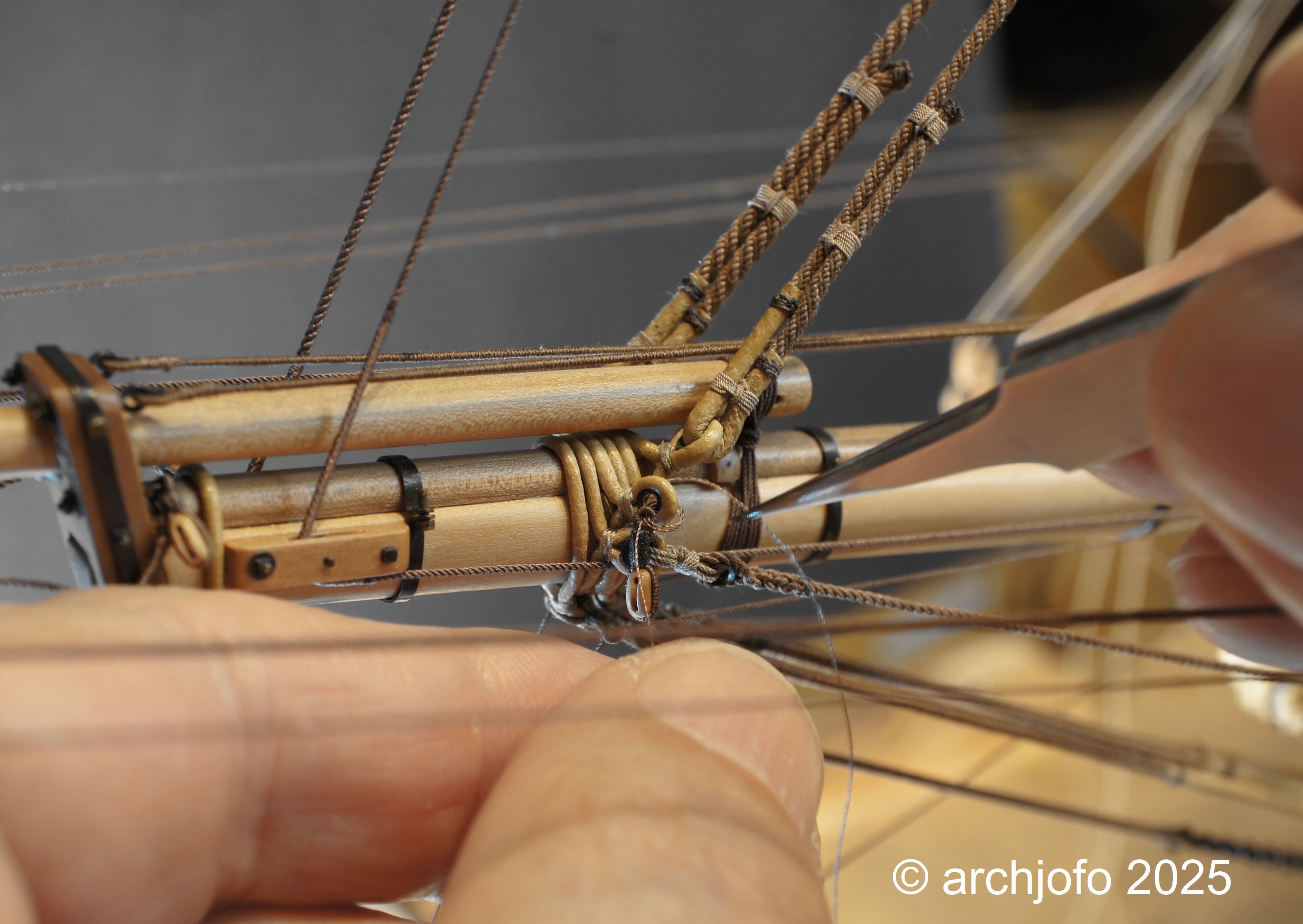
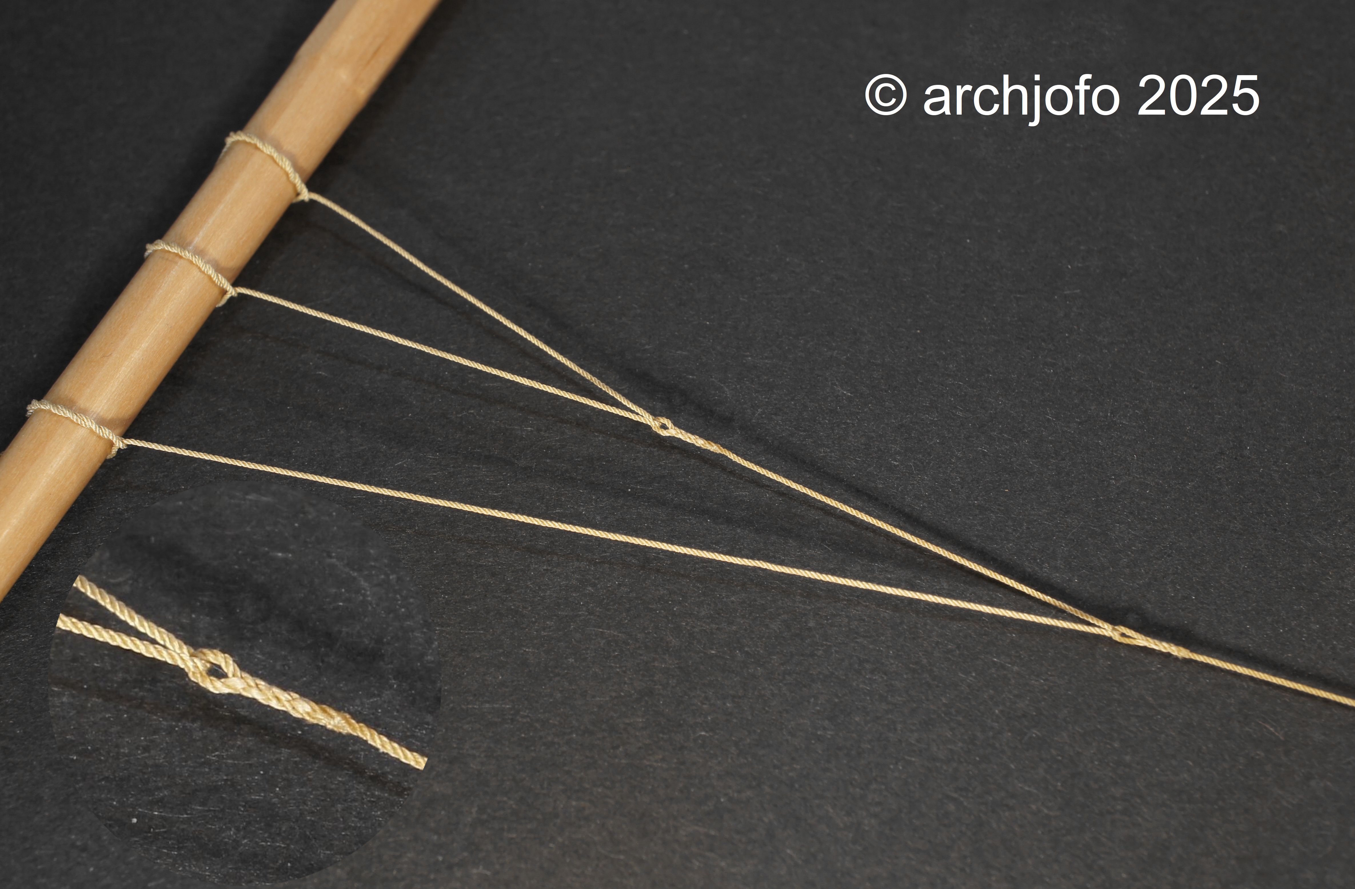
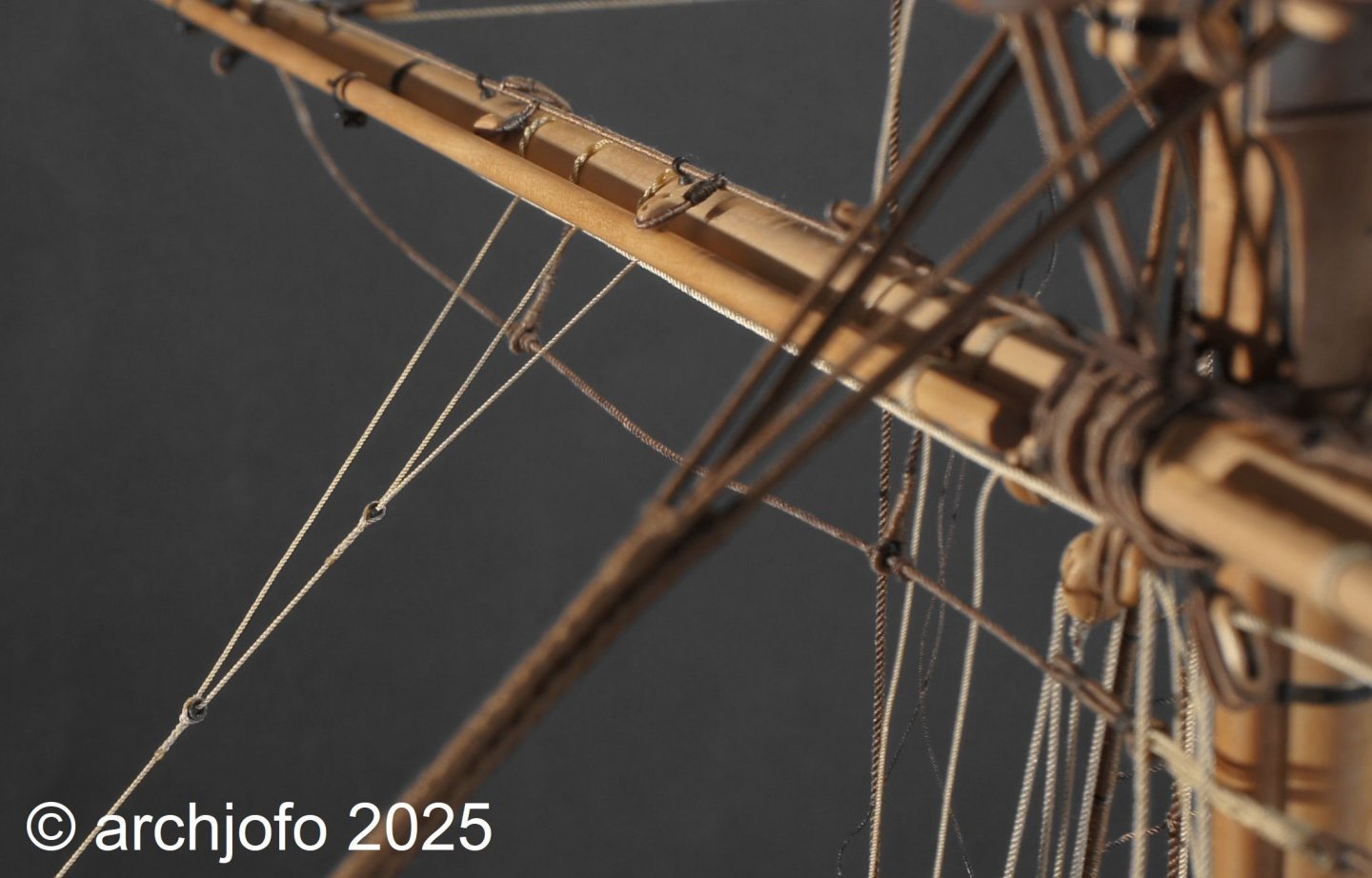
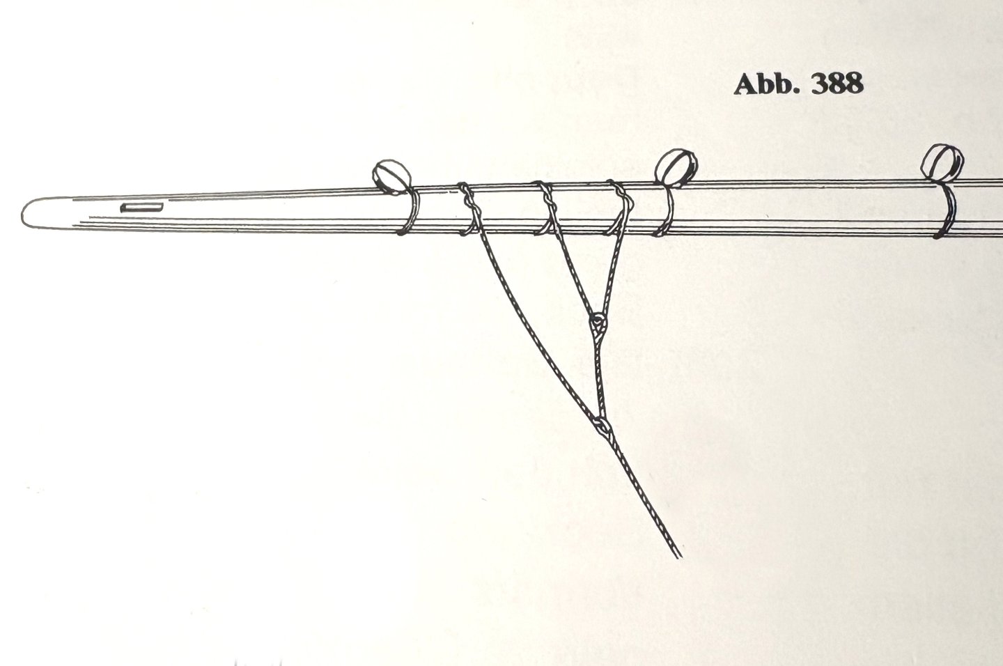
@jdbondy Yes, the Paasch is really very helpful for translating old nautical terms. I can therefore recommend it. Continued: Fore yard – Bowlines / Boulines Since I don't equip my corvette with sails, the question inevitably arose as to how the bowlines are attached. Originally, I intended to simply tie the bowlines around the yard, like on the original Paris model, without bridles. Since I was naturally interested in how bridles work, the next question arose: What happens to the bowline bridles when the sails are taken down? I found the answer to this question in K. Schrage's book – Rundhölzer, Tauwerk und Segel – on page 144. There, you can see an illustration of how the bridle legs are attached to the yard with timber hitches when the sails are taken down. Source: K. Schrage – Rundhölzer, Tauwerk und Segel – p. 144 Since I find this arrangement very logical, I decided to show it this way for my model. Regarding the number of bridle shanks, I'm guided by the monograph, as diverse variations can be found in relevant contemporary illustrations. I intend to implement the bowline bridles as in the original, using real eye splices. The bowline bridles in the foreyard had a diameter of 19 mm (1:48: ø 0.35 mm – 2 x 3 Kimono Japanese silk yarn). Splicing the thin ropes is now very easy. In order to finally attach the bowline, I still had to tie the guide blocks to the bowsprit, as shown in the next picture. I'm also currently working on the correct mooring of the running rigging. But more on that soon. To be continued...


-
@SaltyScot @ccoyle @wefalck Hello, Since I can't be held responsible for my dear colleagues getting headaches ...😁... , I've tried to translate the terms. I hope it's more understandable now.👍
-
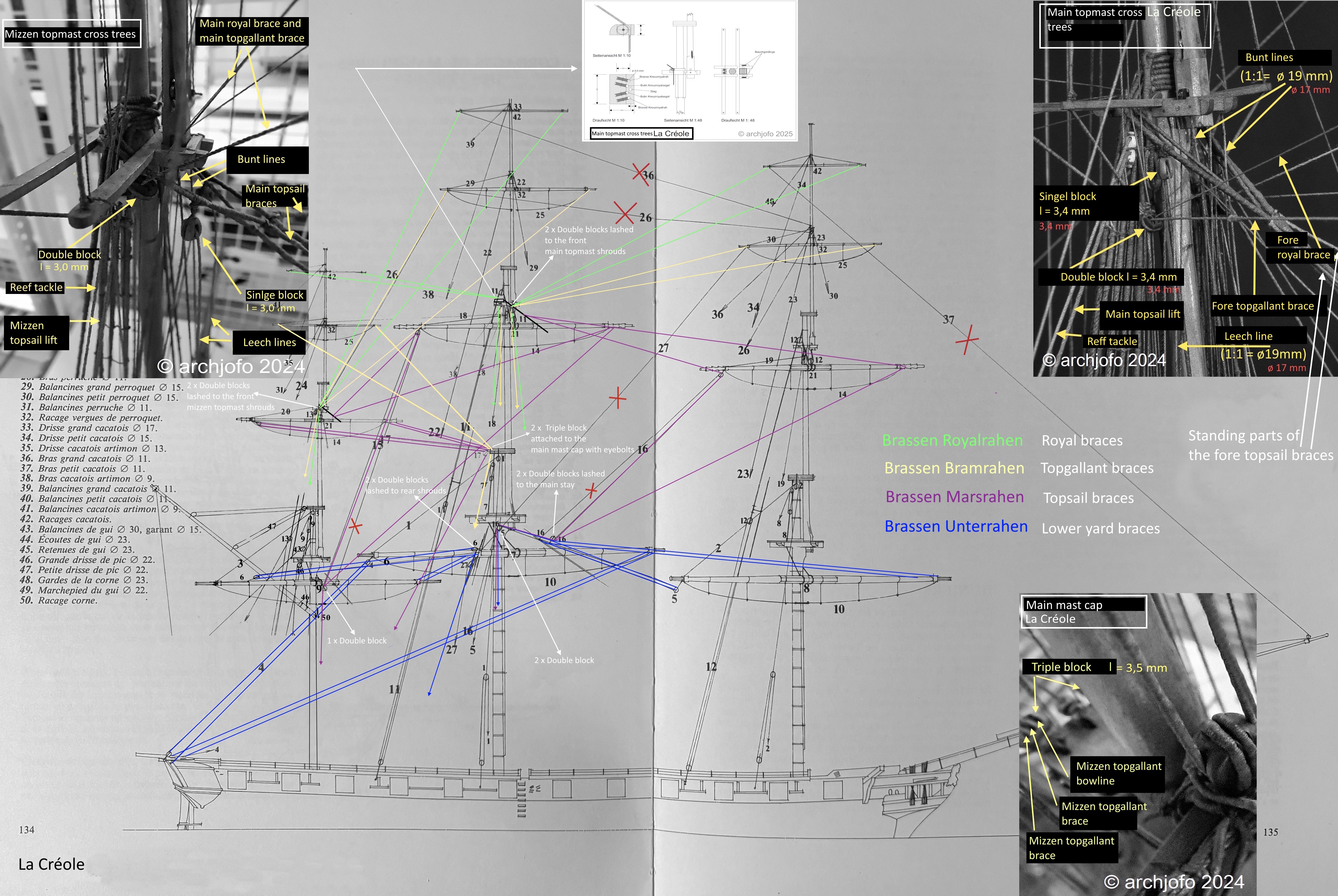
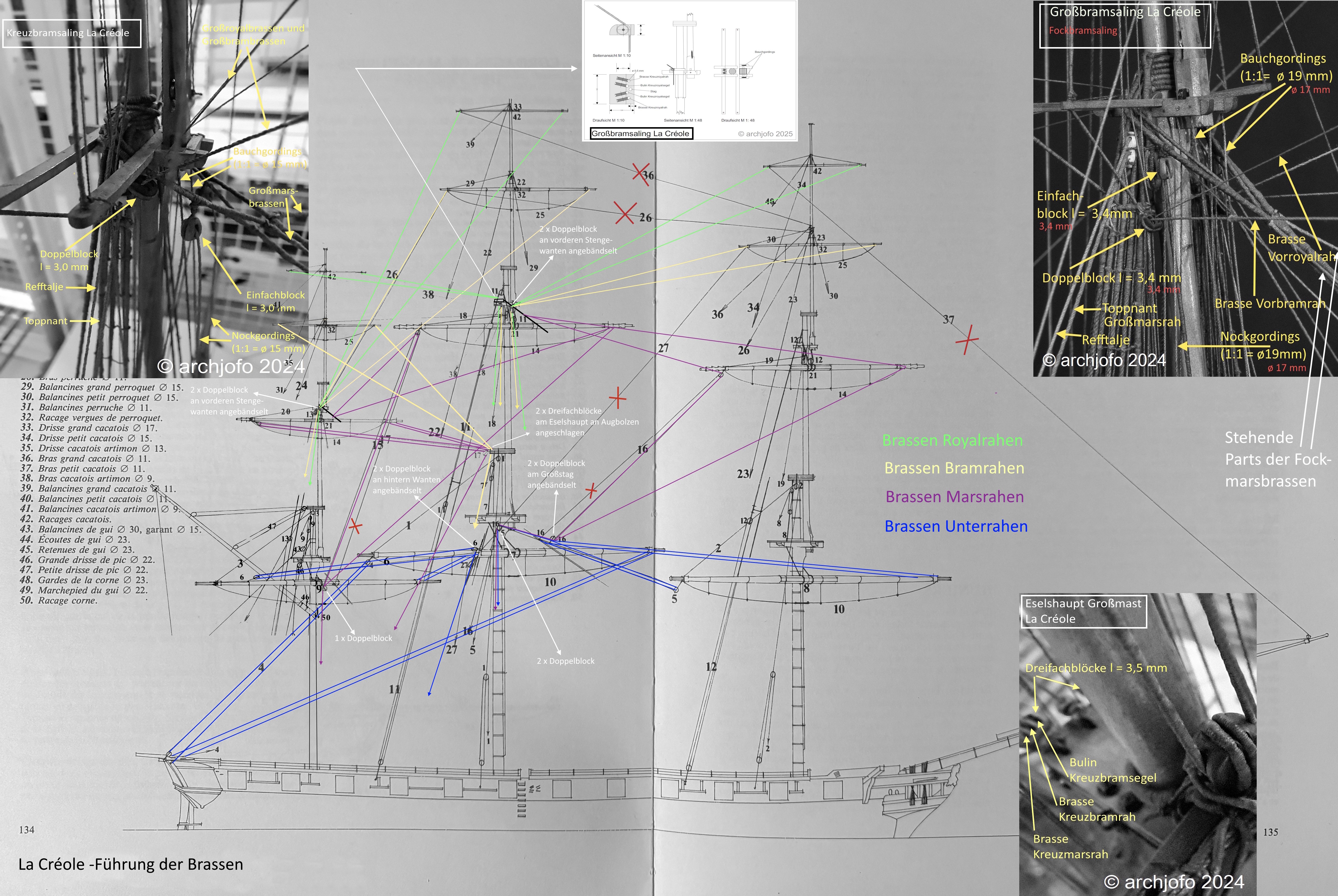
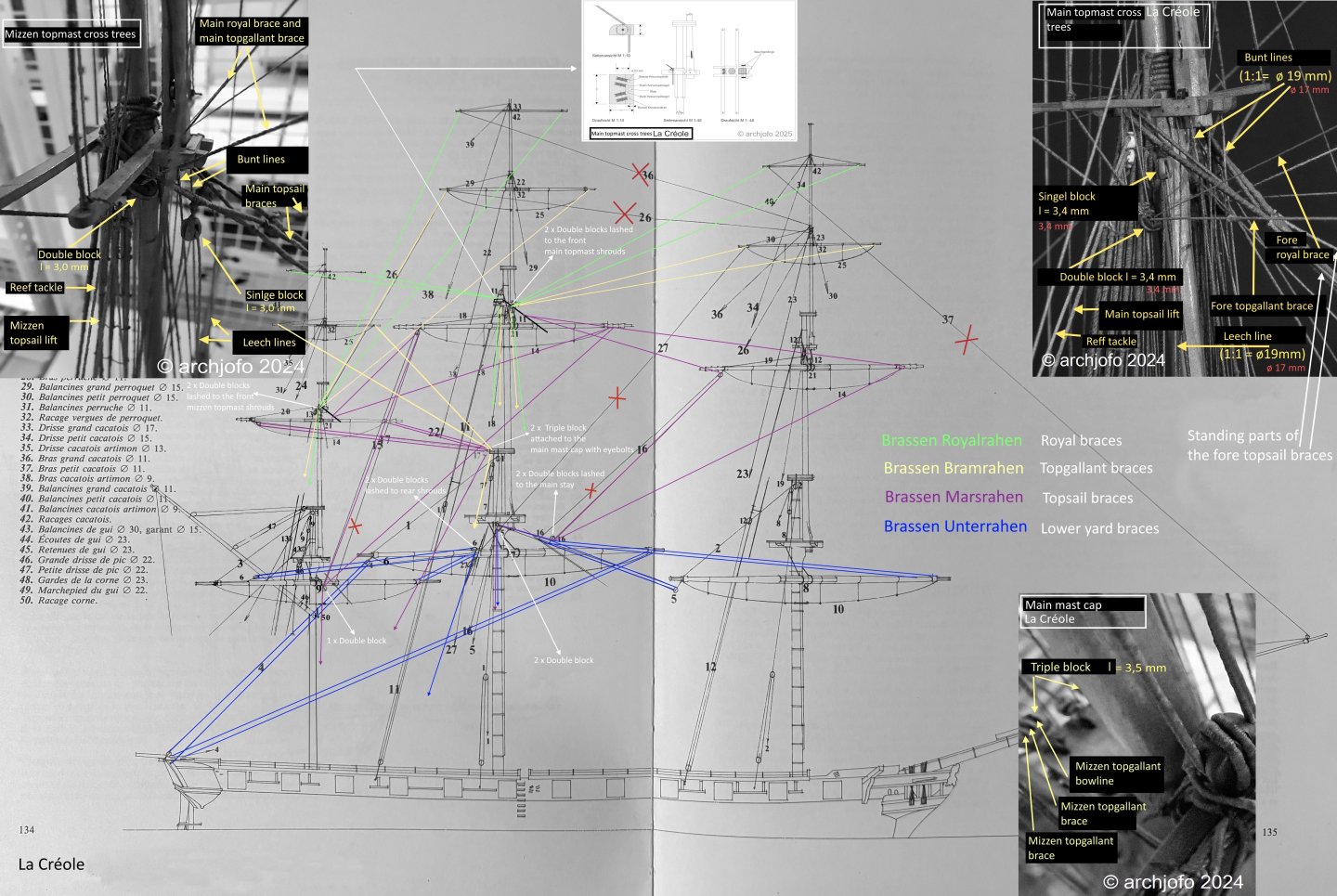
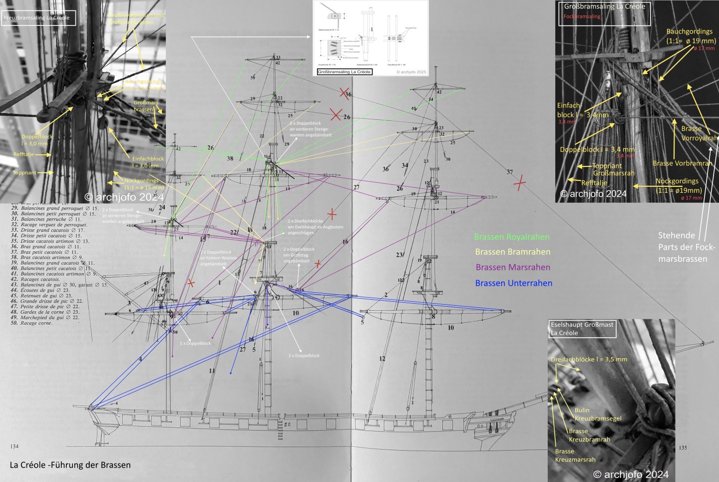
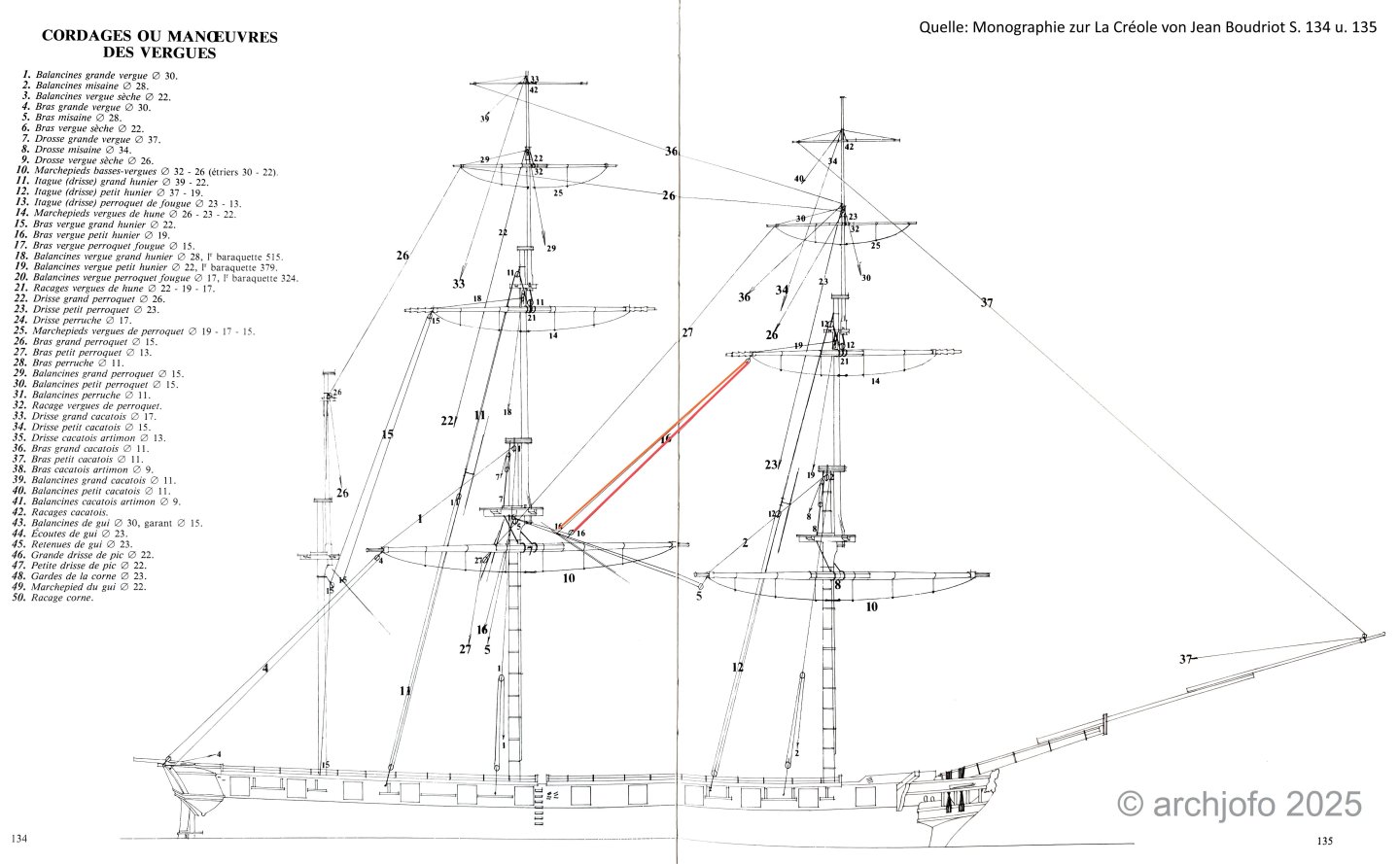
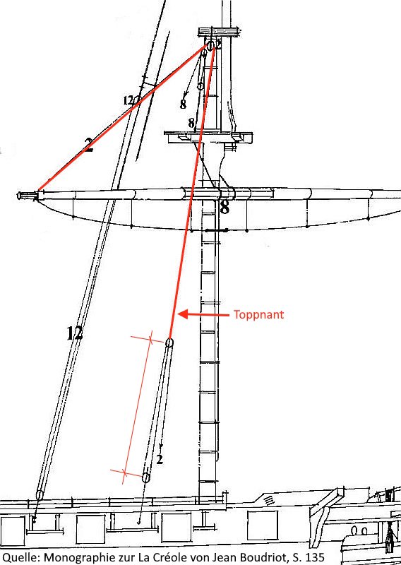
@wefalck @JerryTodd @giampieroricci Hello, I would like to thank you very much for your interest and contributions. And of course, many thanks to everyone else for the likes. Hello colleagues, I've tried to summarize the information I gathered some time ago about the brace routing for my French corvette in a diagram for further rigging work. If you're interested, please zoom in! I hope you'll forgive me for only labeling it in German. But the pictures will explain it to some extent.
-
Hello, I will not follow the monograph regarding the braces, but will instead follow the original Paris model.
-
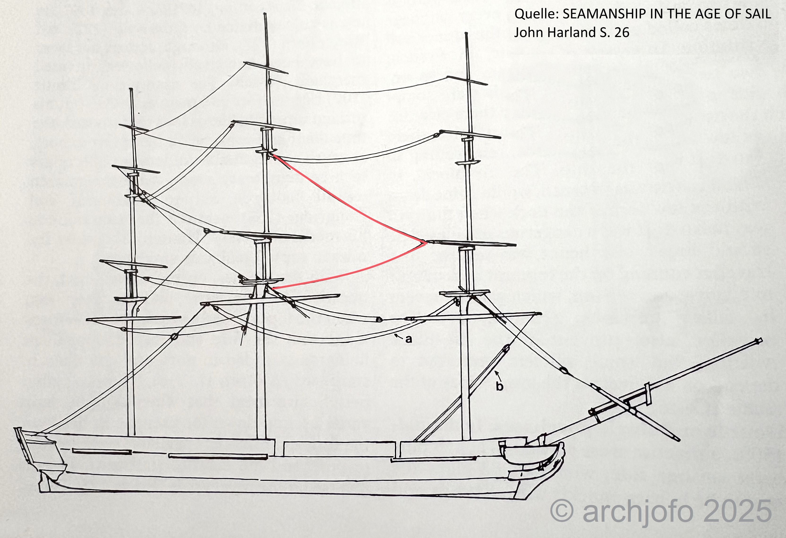
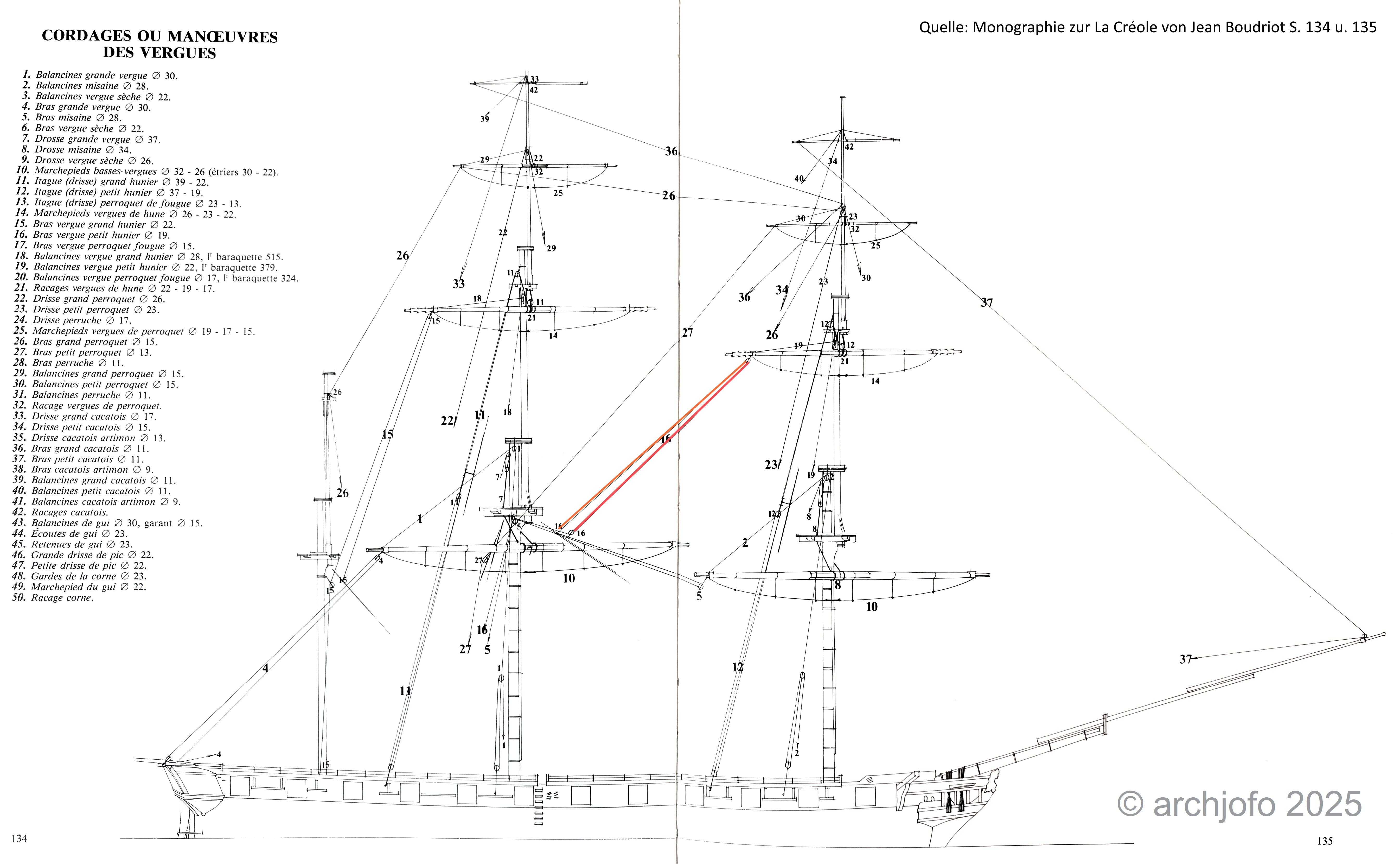
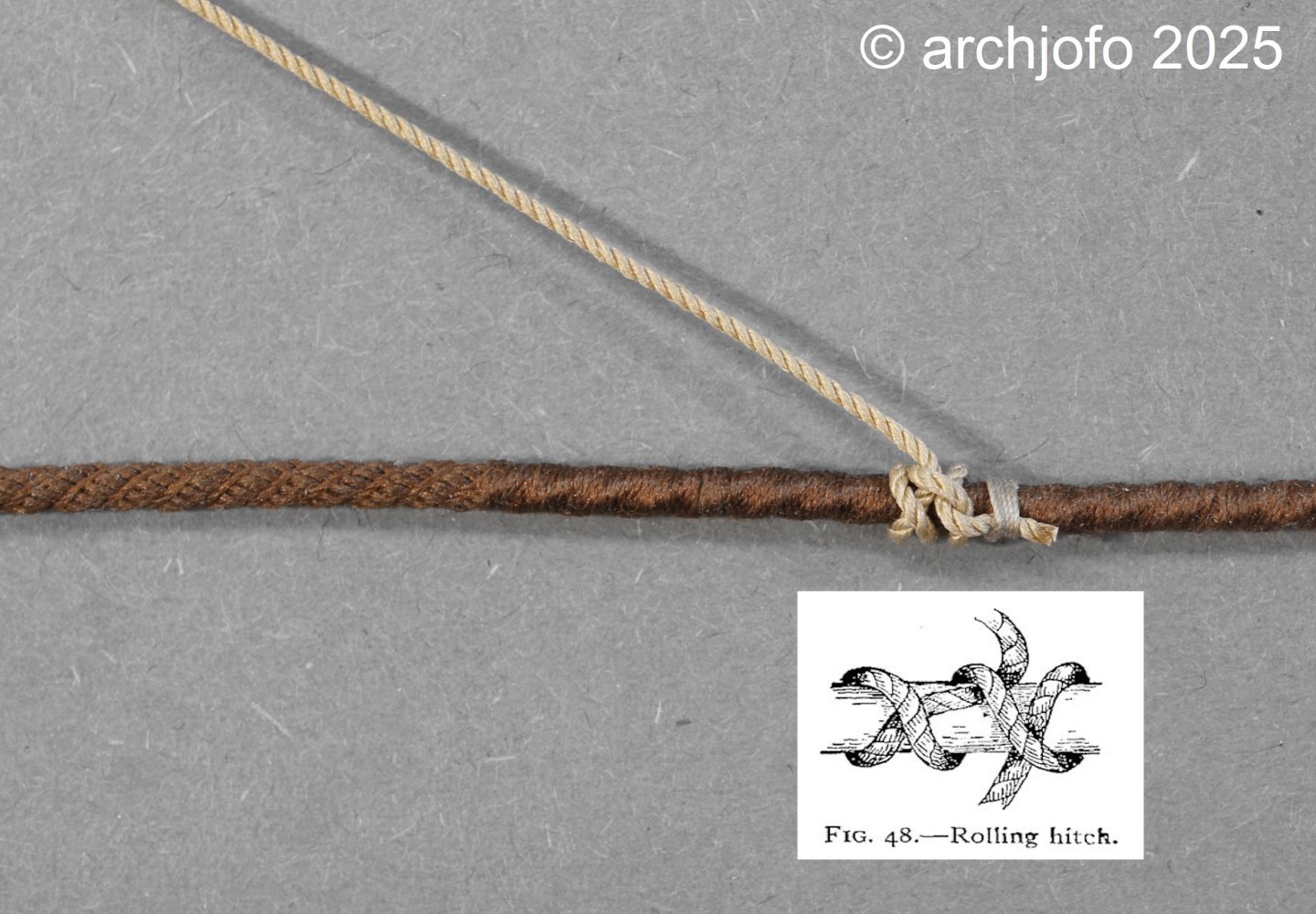
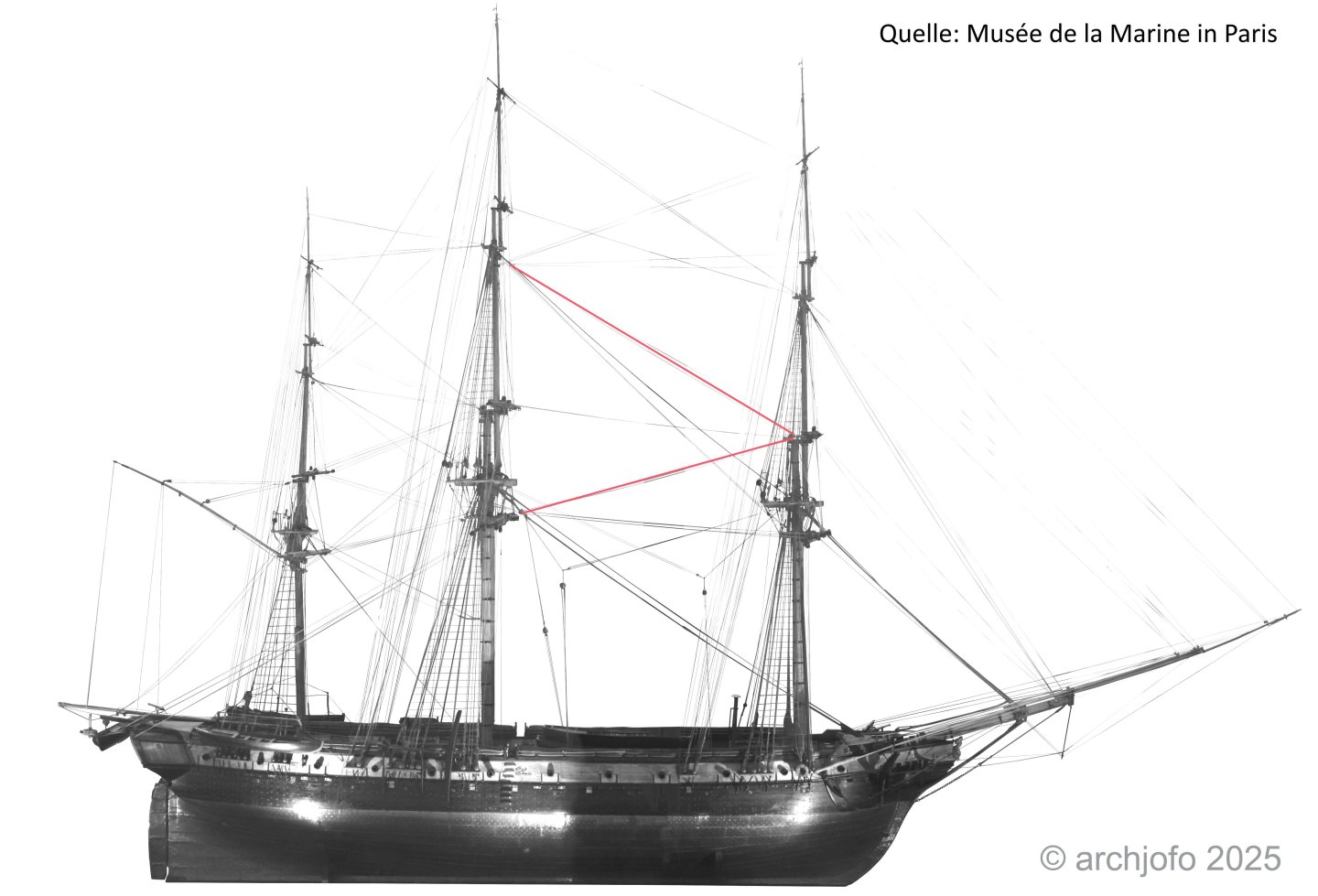
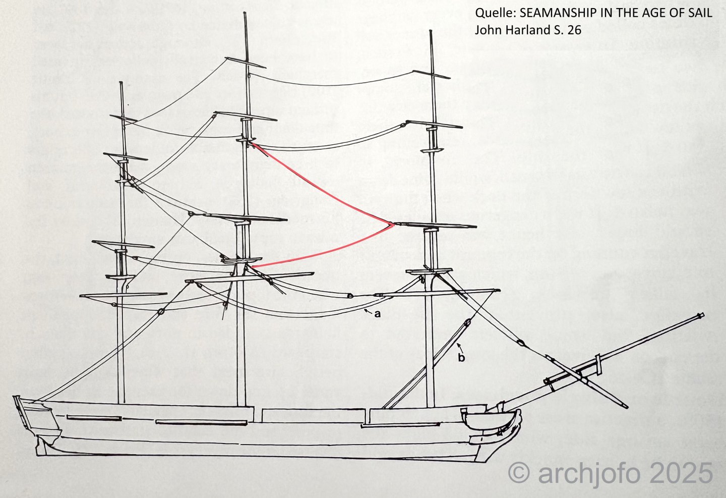
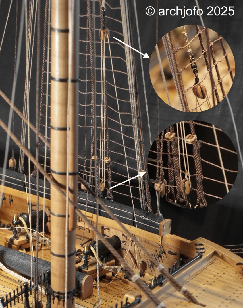
@albert @SaltyScot @Keith Black Hello, It's nice to see that there's still interest in my model after so long. Thank you and everyone for the likes. Continuation: Fore braces / Bras de misaine Before installing the fore braces, I revisited my question regarding the attachment of the standing parts to the stays and tried to gather further information on this topic. Ultimately, based on advice from colleagues in relevant forums, I came to the conclusion that a rolling hitch seems quite appropriate here. In French, this is called an amarrage à fouet. Before attempting the model, I tried tying a knot on a piece of rope. The loose line was secured to the stay using seizing. I find this solution plausible and will therefore implement it accordingly on the model. In this context, there was still a need for clarification regarding the routing of the fore topsail braces, since, according to the monograph, their standing parts should also be attached to the mainstay, where the fore braces are also attached. However, the original Paris model shows the routing of the fore topsail braces differently than in the monograph. The standing parts run upwards to the main topmast stay where they are tied, as shown in the following illustration. The aforementioned routing of the topsail braces was obviously quite common at that time. It should also be noted that the ship models from around 1800 in the Musée de la Marine have split foremast braces, i.e., the running parts run downwards via blocks on the mainstay for mooring, and the standing parts are attached to the main topmast stay. This is also how it is shown and described in the Harland. Therefore, I am once again following the Paris model and not the monograph. To be continued...
-
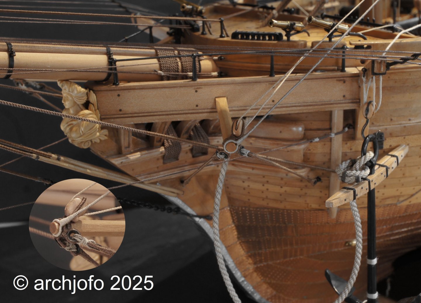
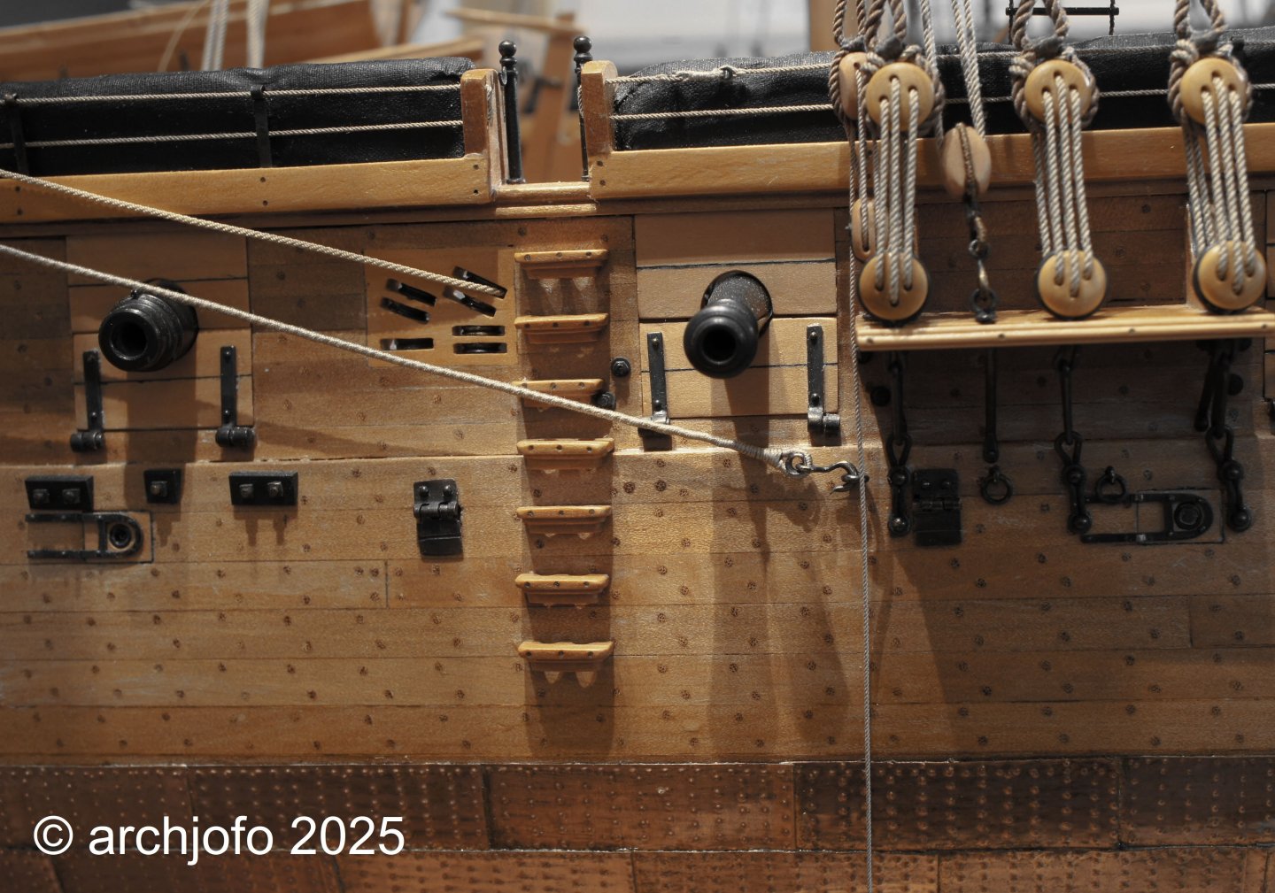
@jdbondy @SaltyScot Thank you so much for your kind comments. I'm very happy about that, and also about the likes from others. JD, yes, that's the silk yarn I use. I also use a silk yarn from KIMONO. Continuation: Fore yard – Sheets and Tacks / Écoutes et amures After some back and forth, I finally decided on the cable version and have now attached the sheets and tacks on the starboard side. For the model cable version, I tried to lay the required ropes as loosely as possible. This resulted in a cable that wasn't too stiff. The first picture shows the arrangement of the sheet, tack, and clew line blocks, which are connected by toggles, as I won't be attaching any sails. The next picture shows the route of the port fore tack on the boomkin with shoulder block. The standing part is protected against chafing in the front area. The standing part of the fore sheet, as can be seen in the last picture, is also protected against chafing in the rear area. The fore sheet runs over a sheave in the ship's side for securing to a cleat. To be continued...

-
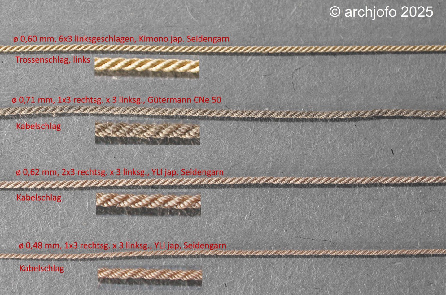
Continuation: Foresail – Sheets and Tacks Before I began attaching the sheets and tacks for the fore sail, I made a few more attempts at making the corresponding ropes, as shown in the following picture. As already described several times, the sheets and tacks for the foresail and mainsail of this corvette were made of so-called grelins (cable less than 12 French inches thick). According to Boudriot's monograph, the diameters of the sheets for the foresail are 30 mm (1:48: ø 0.63 mm) and for the tacks are 23 mm (1:48: ø 0.48 mm). Due to the yarn used, the diameters for the model can only be approximated as closely as possible, for example, 2 x 3 r x 3 l with YLI Japanese silk yarn, which results in a diameter of 0.62 mm. This isn't always as accurate as in the example given here. In this context, I noticed in the monograph that the topsail sheets are thicker than those of the lower sails. The fore topsail sheet therefore has a diameter of 34 mm. After clarifying this matter, which I initially suspected was a mix-up, Gerard Delacroix kindly explained to me that this deviation is quite normal. He referred to "Manuel de gréement par F.-A. Costé, Paris 1829." According to this, these ropes are calculated according to a specific ratio based on the ship's dimensions. The ratio of the sheets for the topsail to the fore topsail is 0.065/0.075. From a purely visual perspective, I believe the left-handed rope would be the better result for the model, as the structure is clearly visible from a normal viewing distance, which isn't as noticeable with the cable-laid rope. But knowing that the cable-laid ropes are closer to the original doesn't make this decision any easier. To be continued...
-
@matiz The hull of the La Creole has wonderful lines. Your execution is simply fantastic. Model building at the highest level! I'm really excited to see what happens next.
-
Continuation: Fore yard - Lifts / Balancine I have already reported in detail on the design and attachment of the La Créole's lower yard lifts in a few previous posts. For their final installation, the only remaining question was how long the lift tackles should be to enable the required maneuvers of these yards. Despite intensive research, I was unable to find any decisive information on this. Accordingly, I based my work on the description in Jean Boudriot's monograph on La Créole. For the tackles I had already prepared some time ago, all I had to do was pull the ropes through the swivel hooks and attach the seizings. The tackles were then attached to the channels using eyebolts. I secured the lanyards, which were routed over redirect blocks, to the inside of the bulwark, as shown in the following photo. Next comes the attachment of the sheets and tacks for the fore yard, which I still have to make as so-called Grelins (in English, cablet: left-handed). Whether I make them only as left-handed hawsers or actually as a cablet is still open. With a diameter of approximately 0.6 mm for the model, the rope would probably be too stiff as a cablet, which I discovered in my initial tests. But more on that soon...
-
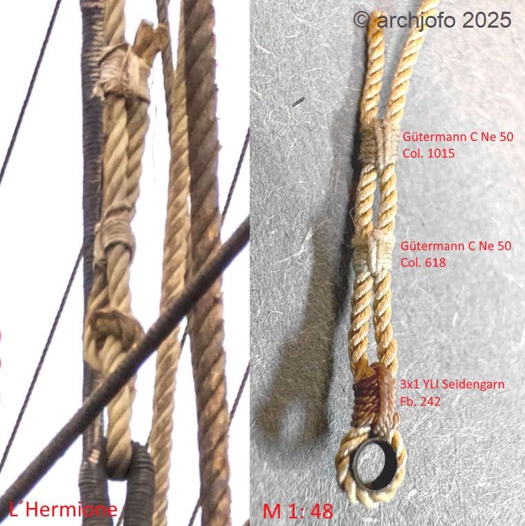
@albert Hello, First of all, I would like to thank you for your interest in my model building. Let's continue with a small detail: Continued: Running Rigging - Seizings Before I continued rigging my French corvette, here the lifts of the fore yard, I asked myself the fundamental question of how and with what I should perform the required seizing of the running rigging. In my search for an example of original rigging, I found what I was looking for in the replica of the L'Hermione. This appears to be the fore topsail halyard, a similar situation to the one used to attach the tackles for the lifts. As discussed several times in another forum, the running rigging was also lightly tarred, as was the spun yarn for the seizing. In the following picture, I have compared three possible seizings for my model with the example from the L'Hermione. Accordingly, I'll opt for the top option, as I believe it's closest to the original. As already mentioned with the standing rigging, the need for thimbles for a sailing ship model is enormous. This, of course, also applies to the running rigging. Therefore, I'll have to make some more thimbles. To be continued...
-
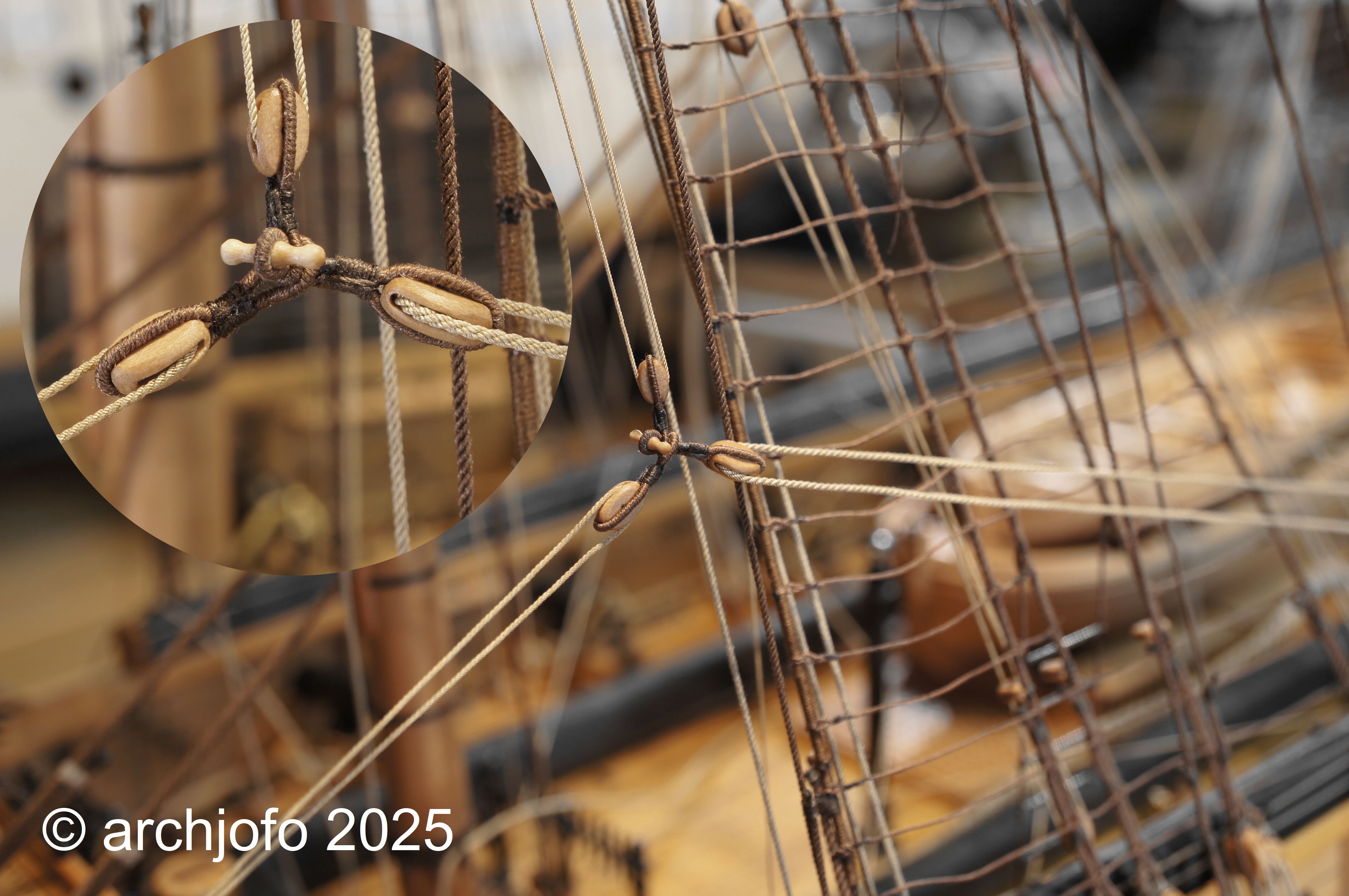
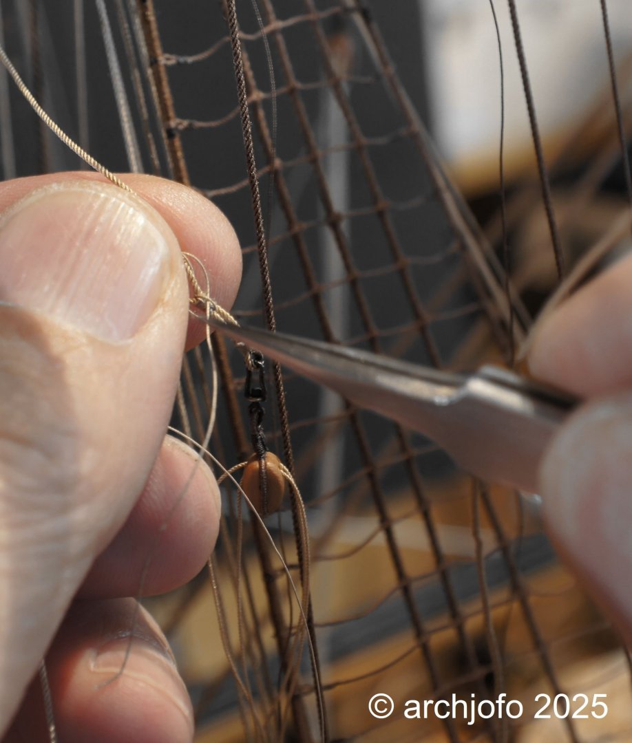
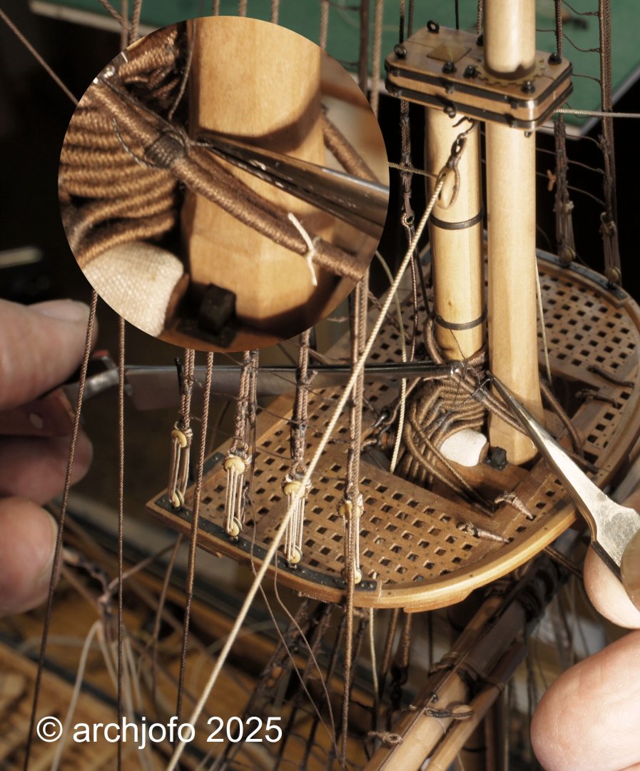
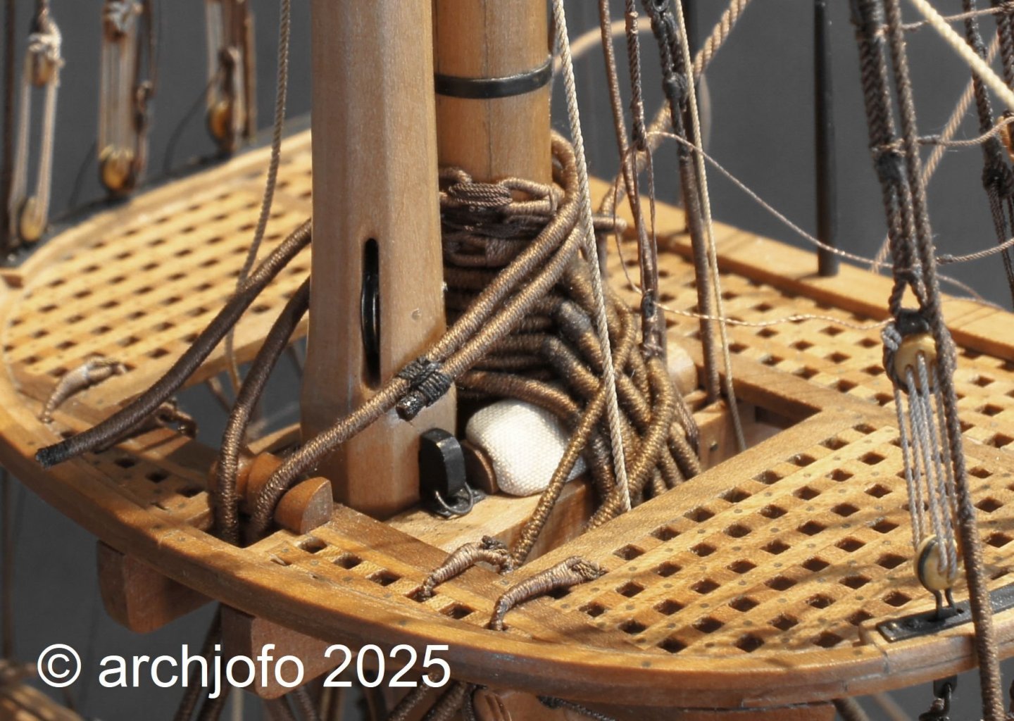
Continuation: Attaching the fore yard - Vergue de misaine - with running rigging Following up to my previous post, here are two more pictures and a brief explanation of how to make a seizing for the sling directly on the model. The first picture shows me holding and securing the two sling ropes together with tweezers on the left. Using the tweezers on the right, I then wrapped the yarn (spun yarn) around the two ropes. I then pulled the yarn through twice between the ropes, perpendicular to the winding. Finally, the end was tucked under one of the two yarns and pulled tight in the middle. I only soaked the free end of the yarn with a tiny amount of superglue. Thin superglue penetrates the yarn well, so that even after trimming off the excess yarn, it is still sufficiently secured. The goal is to make the superglue completely unnoticeable, which doesn't always work perfectly. It's very important not to get the superglue on the seizing itself. Otherwise, the superglue will negatively affect the appearance of the seizing. The result can be seen in the second picture: I hope I made that clear. To be continued ...
-
It's always nice to see new progress in your work. As always, you do a fantastic job. Absolutely clean and precise work. I'm looking forward to seeing the further progress.
-
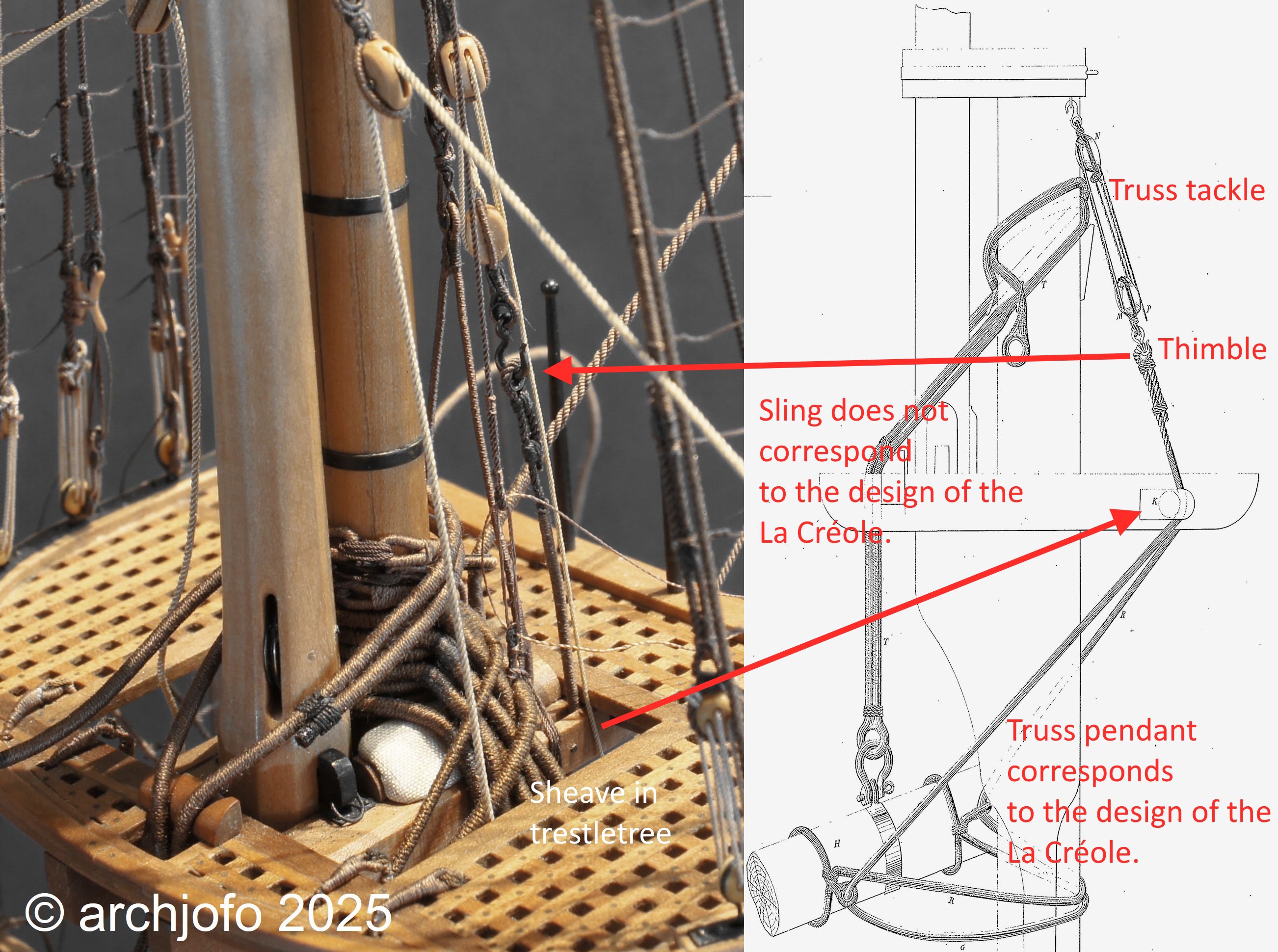
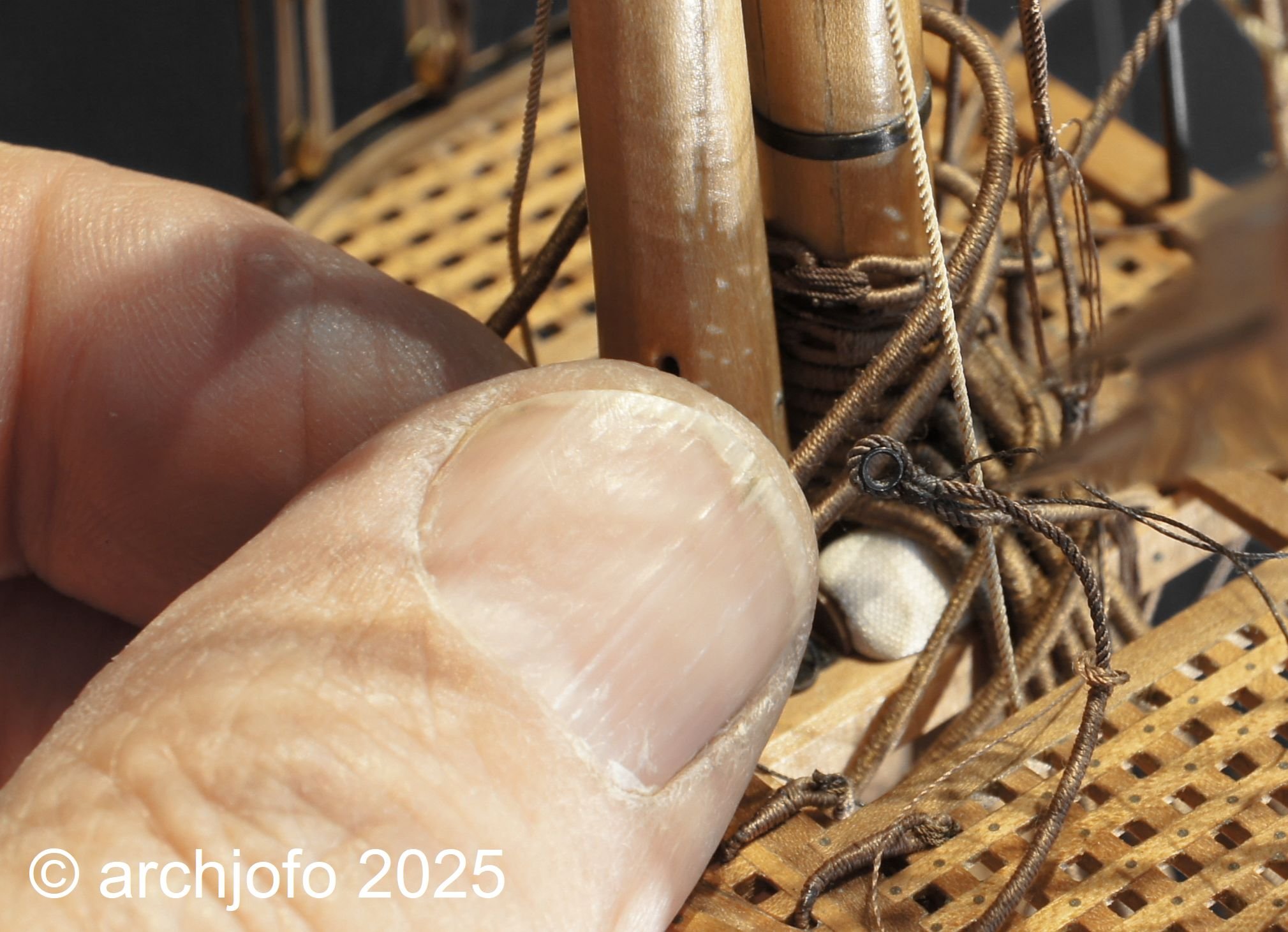
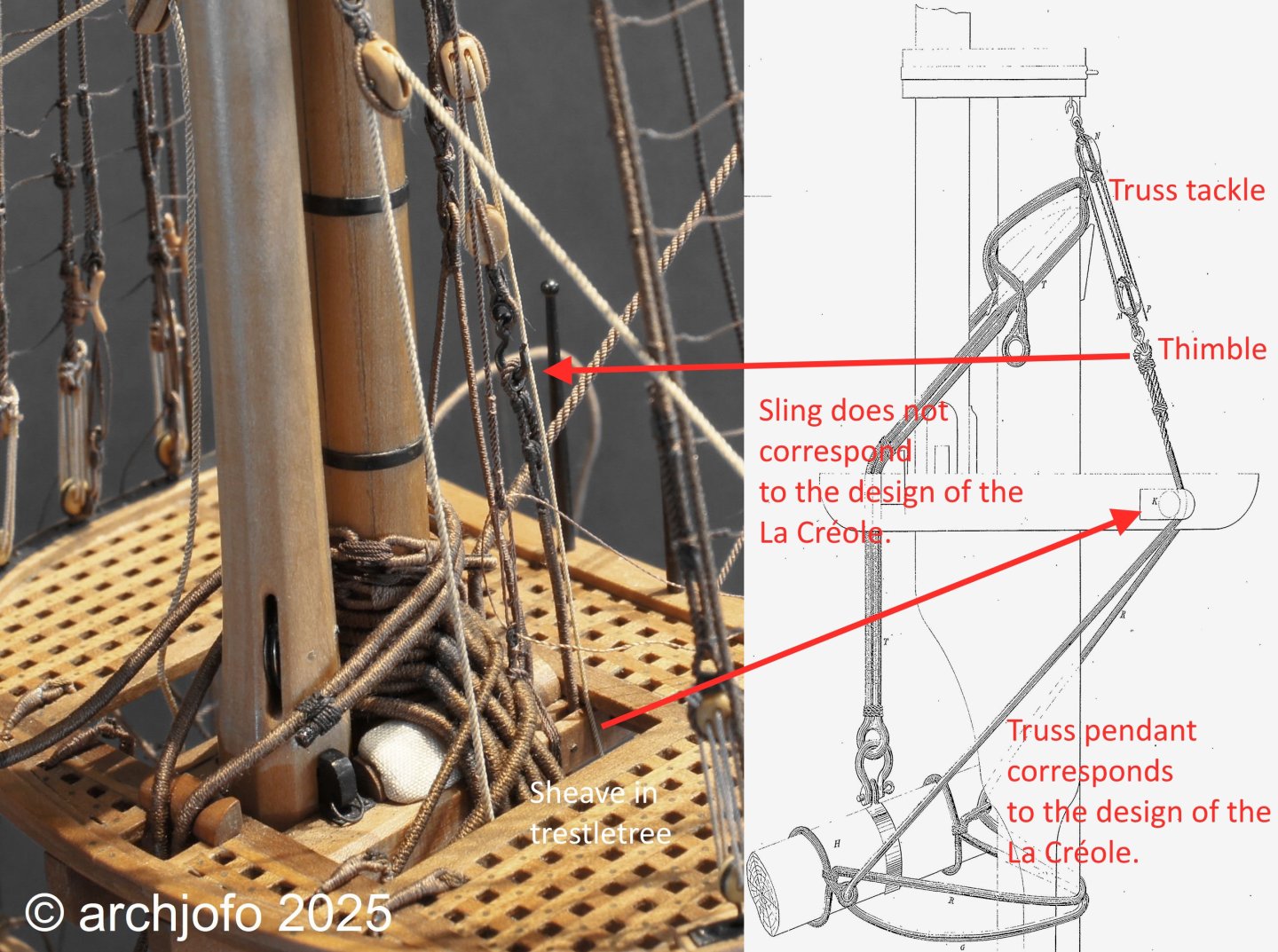
@dvm27 Hello Greg, Thanks for your interest, and I'm genuinely happy if I can give a master model maker some inspiration. Obviously, my translation is a little misleading, so I apologize for that. But I tried to explain that the ends of the truss pendants with the integrated thimbles don't go through the sheaves in the trestle trees. Therefore, the thimbles can only be inserted after the ends of the truss pendants have been pulled through, as in the original. For a better understanding, I've illustrated this situation with a picture. I think this type of truss pendant is probably very specific to French rigging in the early 19th century.
-
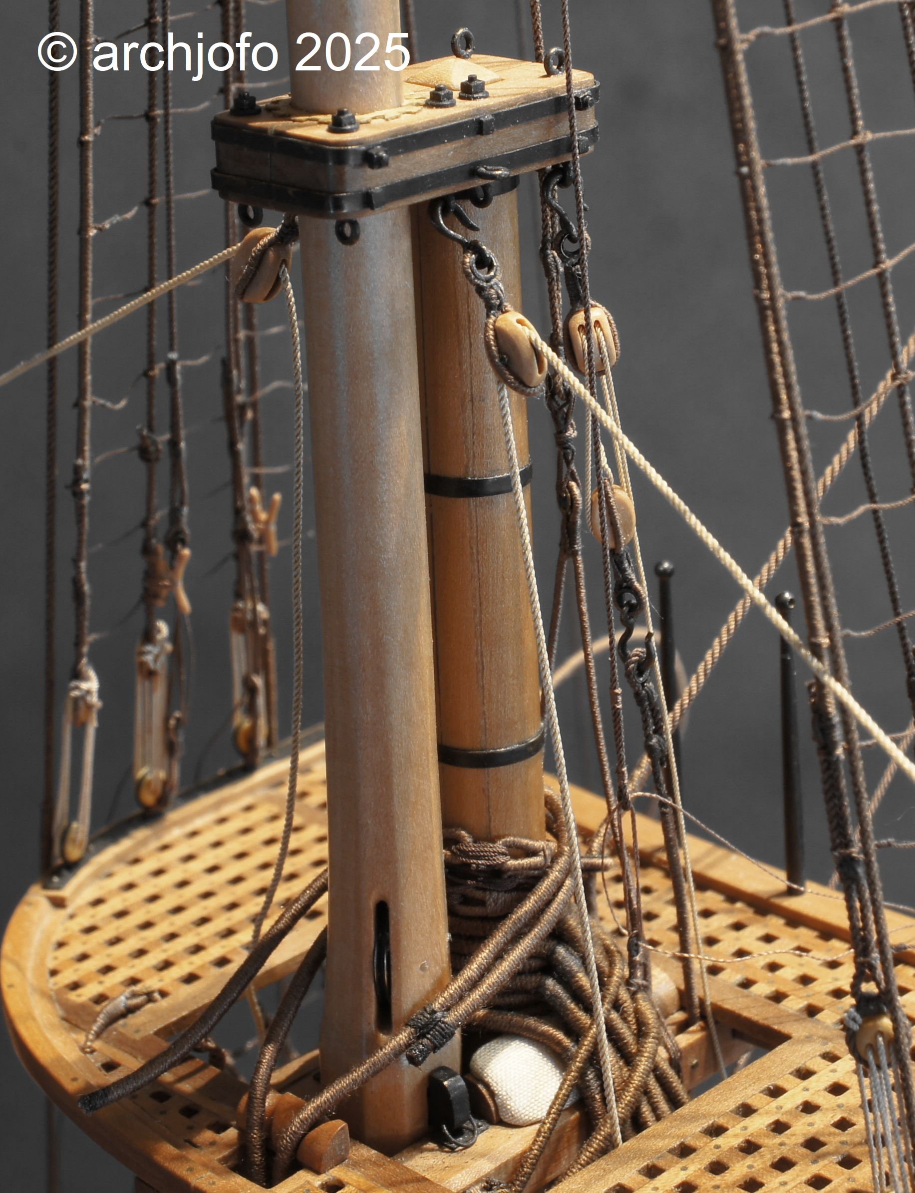
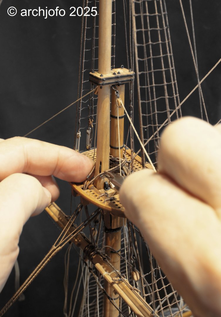
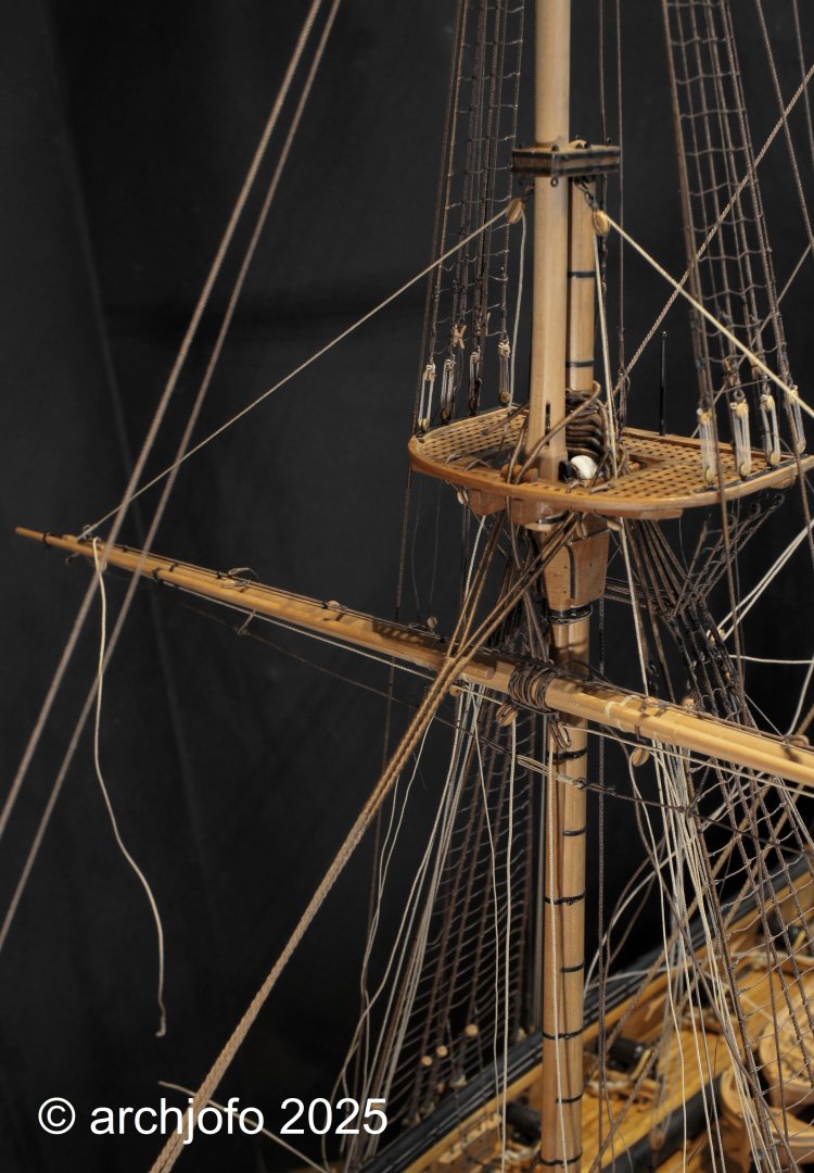
@wefalck @jdbondy @matiz @albert Thank you very much for your encouragement. It's very motivating, especially when it comes to the very tricky work in the rigging. You always have to be extremely careful not to get caught on something. Also, many thanks to everyone for the likes. Continuation: Attaching the fore yard - Vergue de misaine - with the running rigging Attaching the seizings to the slings was child's play compared to tying thimbles to the ends of the truss pendants. The prepared truss tackles will then be hooked into these thimbles. Therefore, the thimbles could only be tied in afterward. Before doing so, a section of the serving at the rope ends had to be removed. As already mentioned, I then hooked the prepared truss tackles into these thimbles and the corresponding eyebolts on the cap and led the running ropes down over redirection blocks to the fife rail behind the foremast for belaying. More on this soon...


-
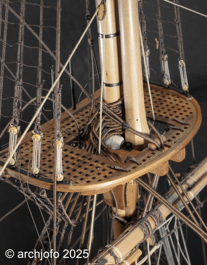
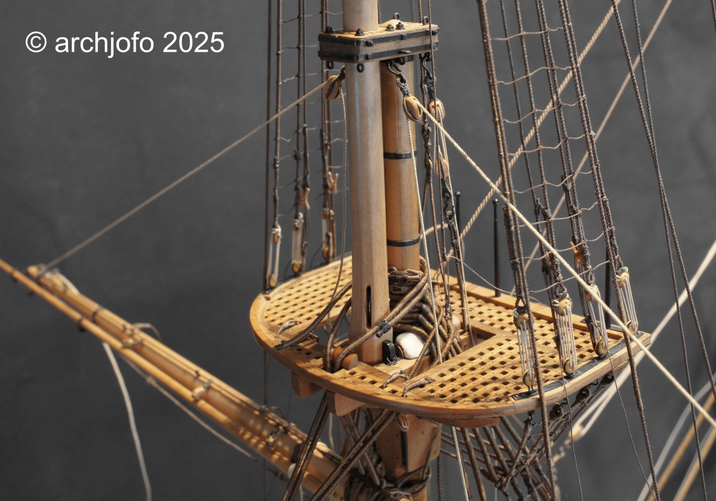
@jdbondy @Knocklouder Thank you for your interest and the nice comments. Also, thank you all for the likes. Attaching the Yards with Running Rigging: Foreyard - Vergue de misaine The final rigging of the model of La Créole began with the attachment of the fore yard and running rigging. The first step is to suspend the yard using the slings. These consisted of strong ropes with a diameter of 43 mm (0.90 mm in 1:48), fully served. While jeer blocks were probably a permanent part of the rigging in the past, towards the end of the 18th century the French began removing the jeer blocks after hoisting the lower yards, as they realized they were not absolutely necessary for holding the yards. Thus, the slings carry the weight of the yard. This was certainly a relief and an advantage when sailing sharply. For the model, I first provisionally positioned the foreyard using the lifts, so that I could then place the slings around the mast and connect them using seizing. The required seizing must be applied directly to the model. Getting this done cleanly and correctly will certainly not be easy. But more on that soon...
-
Hello, This will be an interesting model ship, with lots of insight. Sorry, I may have missed it in your post. What plan are you using to build it from scratch?
-
Brig Le FAVORI 1806 by KORTES - 1:55
archjofo replied to KORTES's topic in - Build logs for subjects built 1801 - 1850
Wonderful cleats ! -
Brig Le FAVORI 1806 by KORTES - 1:55
archjofo replied to KORTES's topic in - Build logs for subjects built 1801 - 1850
Very smart and clever the way you made the carriage wheels and the trunnion caps. But aren't the carriage wheels a bit too small? I think the drawing shows different proportions. -
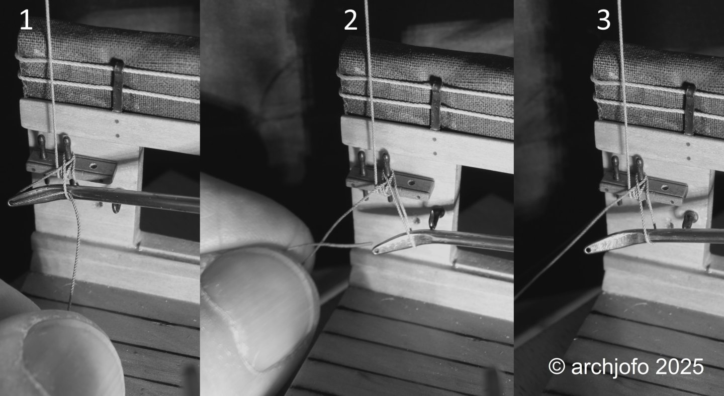
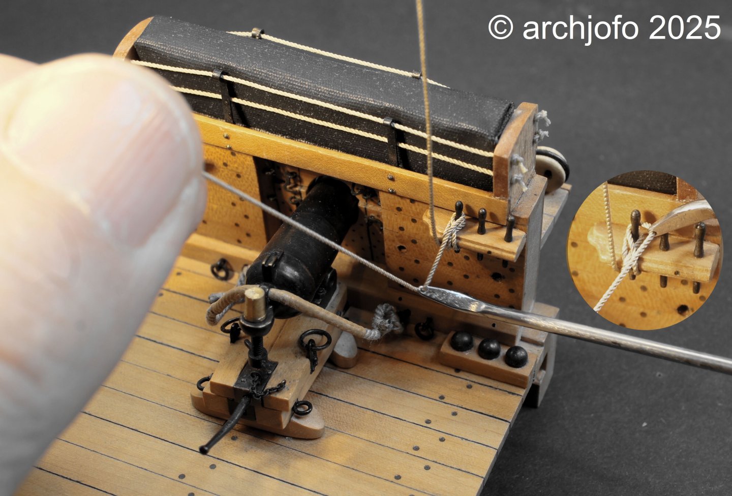
@Keith Black @druxey @Thukydides @Dr PR I am very grateful for your interest and the nice comments. I would also like to thank everyone else for the LIKES. Hello Phil, I'm very pleased if my reports are of any use to you. I also benefit from other colleagues. My understanding of a forum of this kind is give and take, to help us all become better model builders. Hopefully the belaying needle can be a solution to your rigging problems. Addition: Securing the ropes of the running rigging with a belaying needle It is obvious to me how the last loop is to be guided when securing the ropes of the running rigging with a belaying needle. However, this is not clear from my previous illustration on this subject. A model maker colleague asked a question on this. In this respect, I would also like to explain this step here with this additional explanation: As can be seen in Fig. 1, the rope can be guided under the last loop with the belaying needle. In the second step, the rope is then unthreaded by pulling it back, if necessary with the help of tweezers in hard-to-reach places. Fig. 3 shows that the belaying needle can simply be pulled out of the loop by tightening the rope. I hope I have explained it clearly enough. For me, these processes are easy to carry out, as I have already done them many times.
-
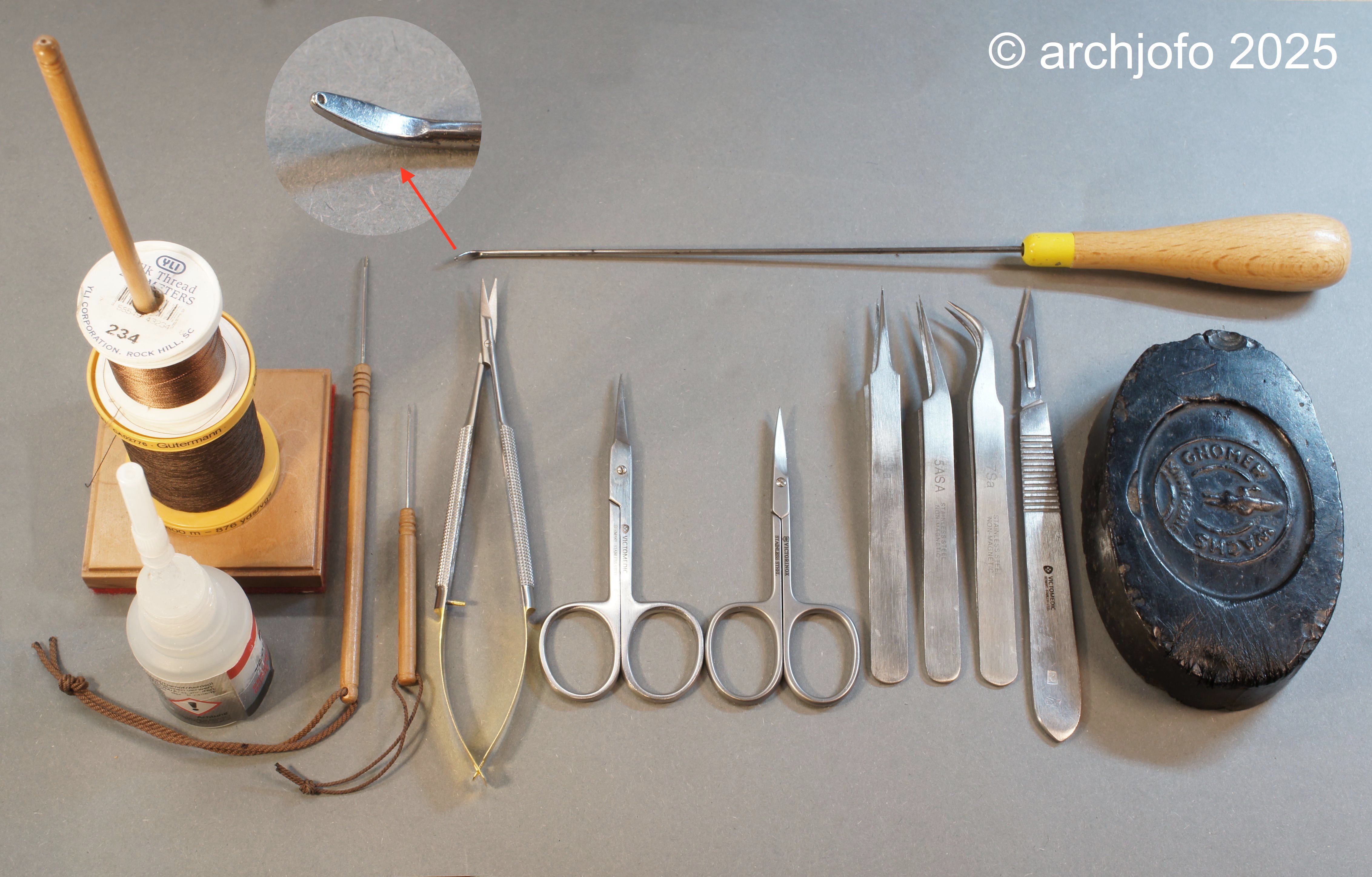
Preparing the final rigging I cleaned up my small basement shipyard as much as I could and took the little French girl out of her "exile" (dust cover). She was then positioned on my height-adjustable platform so that she could be accessed from two sides for rigging, as far as space allowed. It has been a long time since I did the final rigging of a model ship (over three decades). So I tried to refresh my modest knowledge of rigging work for the running rigging of sailing ship models, to acquire new knowledge about it and to think about the further process. I had already raised the question in various forums about which direction and order the model should preferably be rigged in? There was a mixed opinion about when to start rigging, whether at the front or the back. However, everyone agreed that rigging should be done from the bottom up. Contemporary works note that the usual rigging process began with the bowsprit. In order to have fewer disruptions caused by ropes that have already been set, I follow the philosophy of starting from the beginning and then working yard by yard from bottom to top and from belaying point to belaying point. For belaying pins and cleats, I use a belaying needle that I had used as a boy when building the "Adler von Lübeck". I made this according to Graupner's instructions from a steel knitting needle that is around 27 cm long and has a handle and is slightly bent at the other end over a length of around 10 mm. I forged out the front end of the bent part and shaped it accordingly with a file. Close to the filed front edge, I drilled a hole with a diameter of 0.5 mm, similar to the eye of a needle. Many people will certainly know that Karl Heinz Marquardt was responsible for the plan processing for Graupner's "Adler von Lübeck" and was involved in the development of the kit. In this respect, I assume that the description for making this belaying needle also comes from him or was suggested by him. He was also an excellent model maker. What I often see is that many model makers mainly use hooks or tweezers for belaying. However, I have managed very well with my homemade belaying needle so far, as the rope can be guided safely and tightly even in hard-to-reach areas. Therefore, I will continue to use it, including for this model. With the next picture, I want to illustrate how this belaying needle is basically used. Following the recommendations of fellow model makers, I also got myself a pair of Castroviejo micro scissors in order to sensibly expand my rigging equipment. In the following picture I show a compilation of my most important tools for rigging: -Belaying needle -Stand for thread rolls -Superglue with cannula (ø 0.3 mm) -Hollow spike, ø 1.2 mm and ø 0.8 mm for splicing -Micro scissors according to Castroviejo -Thread scissors, straight and curved -Tweezers, straight, curved and offset -Scalpel -Shoemaker's wax for "sailor's thread" This article heralds the last chapter of the model building of the French corvette "La Creole" on the long road to the goal. Once again I would like to thank my many companions, with the hope that they will get through the final stretch with me. So, see you soon...

-
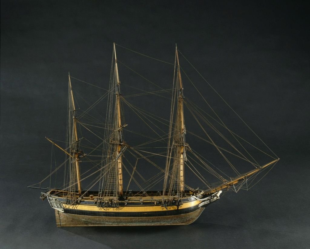
Hello Bob, In my opinion, your model is definitely the L'Astrolabe from 1812. There is a contemporary model of this French corvette in the Musée national de la Marine in Paris. Here is a picture of it:
-
The Astrolabe, a French corvette, an interesting project.
-
This is a good learning project for rigging a model ship.
- 80 replies
-
- 1
-

-
- rigging/masts
- NRG
- (and 2 more)
-
Brig Le FAVORI 1806 by KORTES - 1:55
archjofo replied to KORTES's topic in - Build logs for subjects built 1801 - 1850
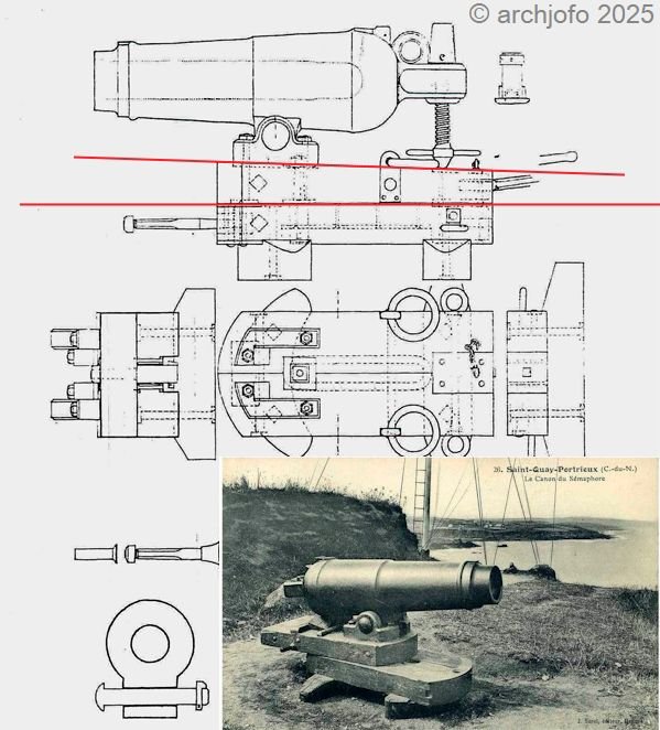
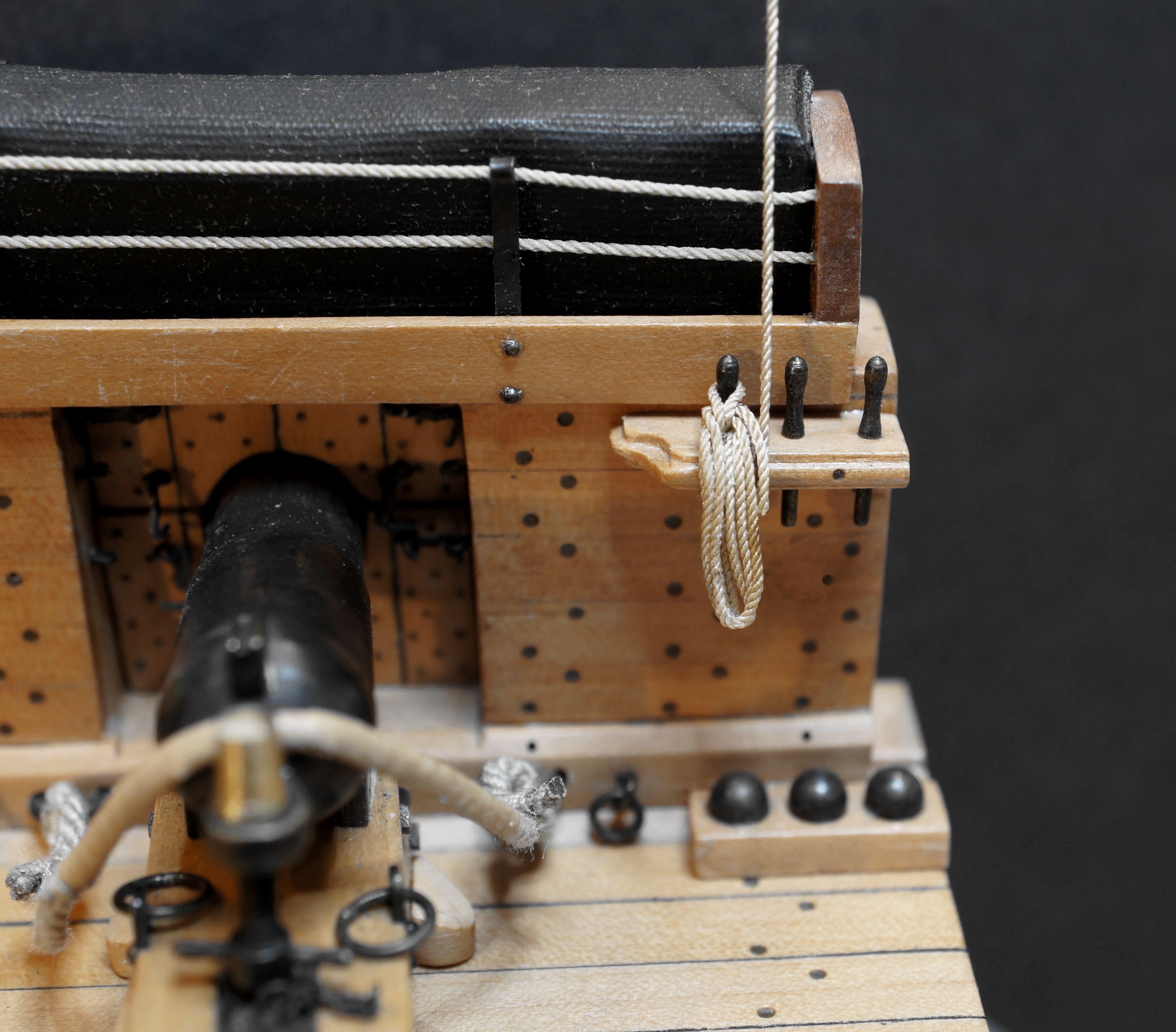
Hello Kortes, I am an admirer of your model-making skills. You have made these carronades with great finesse and precision, like all of your wonderful models. As I have now seen, the upper parts of your carriages are equally strong at the front and rear. As you also value historical accuracy, I did not want to withhold the following information from you. I studied the carronades for the La Créole intensively during construction. Accordingly, I noticed that the upper part of the carriage tapers slightly towards the rear. I have marked this with red lines on the drawing section of the monograph. This taper is also clearly visible on the historical black and white photo of a French carronade.