HOLIDAY DONATION DRIVE - SUPPORT MSW - DO YOUR PART TO KEEP THIS GREAT FORUM GOING! (89 donations so far out of 49,000 members - C'mon guys!)
×


archjofo
-
Posts
1,498 -
Joined
-
Last visited
Content Type
Profiles
Forums
Gallery
Events
Everything posted by archjofo
-
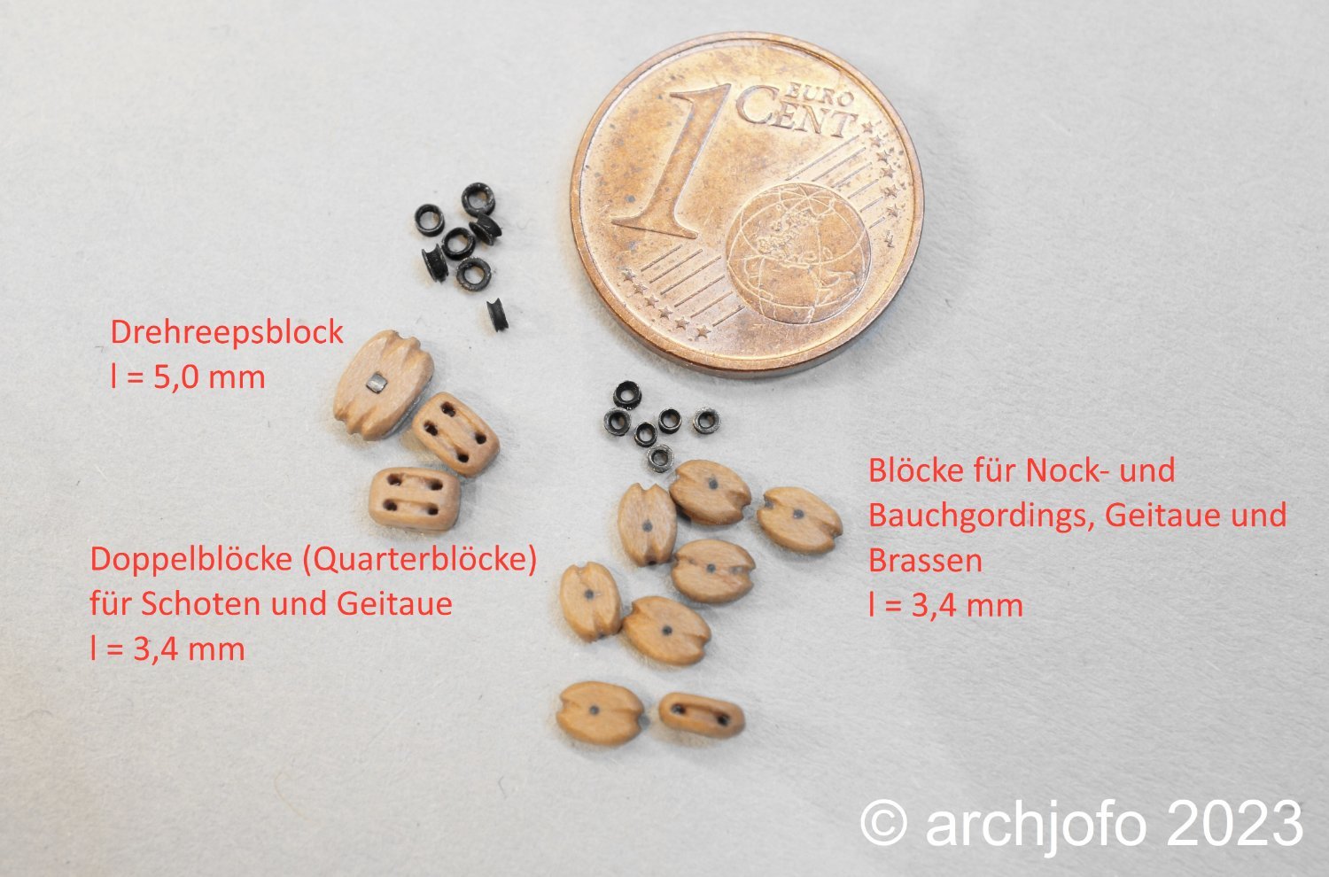
 Perhaps I might add, basically there are quarter blocks with one disc, so-called single blocks, and with two discs, so-called double blocks. In the lower yards, the quarter blocks were large single blocks to guide the sheets. The clew lines were managed in separate blocks. In the topsail and topgallant yards, quarter blocks were arranged as double blocks to guide the clewlines and sheets together approximately in the middle of the yard. Since the clew lines are usually thinner than the sheets, these double blocks usually also have different disc gates. Therefore, these blocks are also called thick-and-thin blocks.
 -
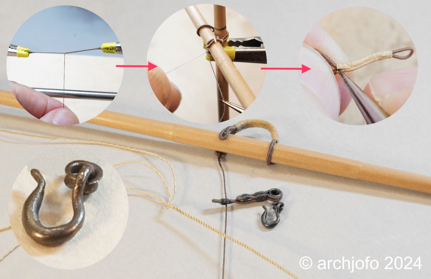
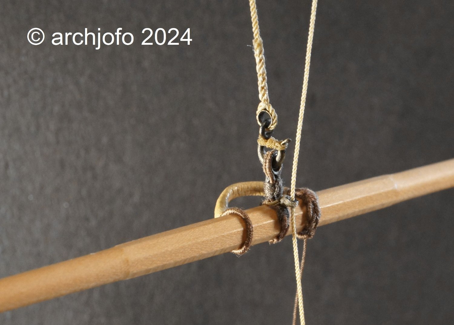
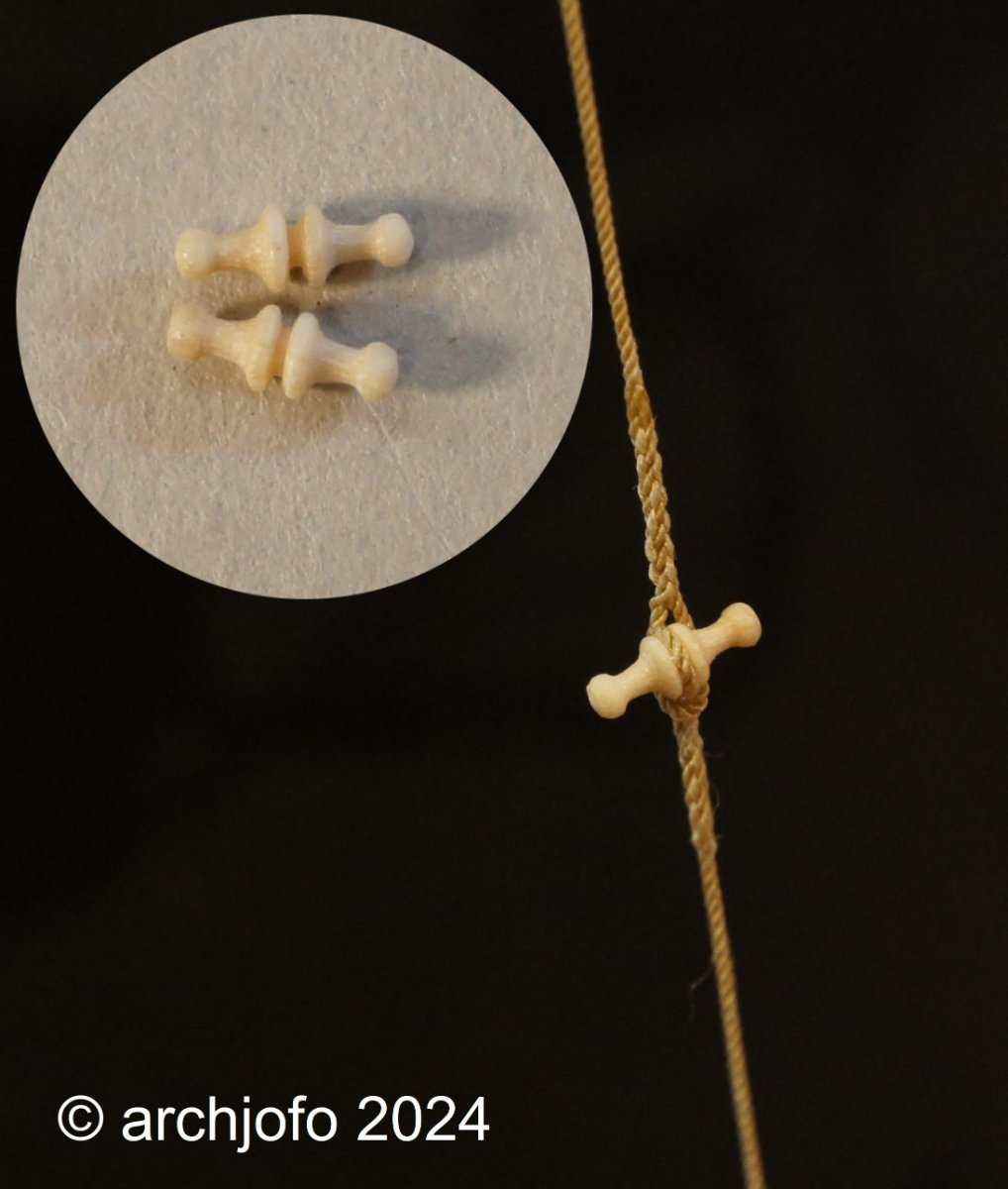
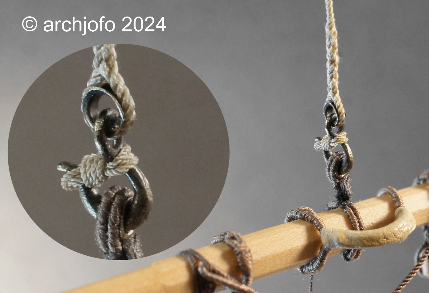
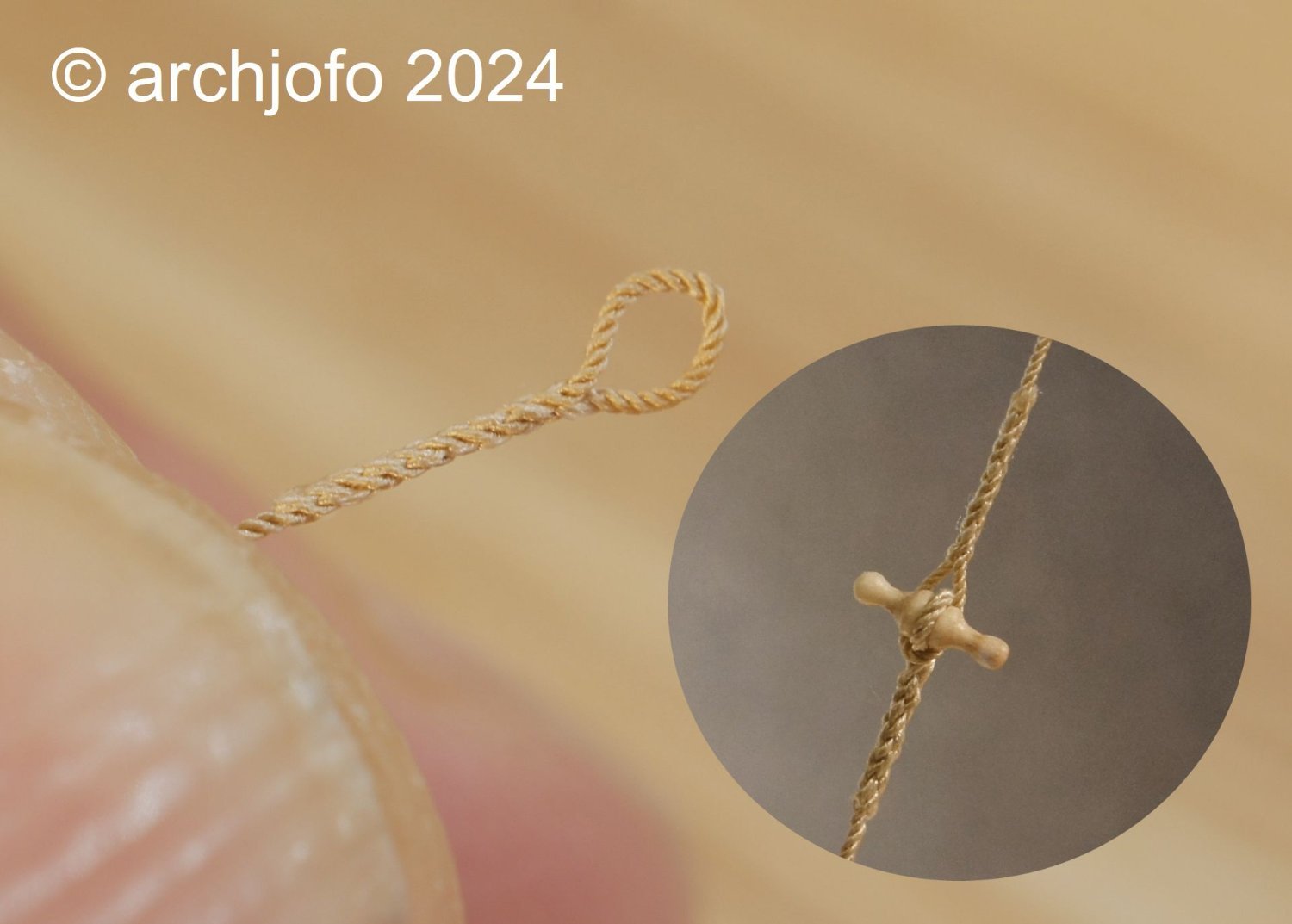
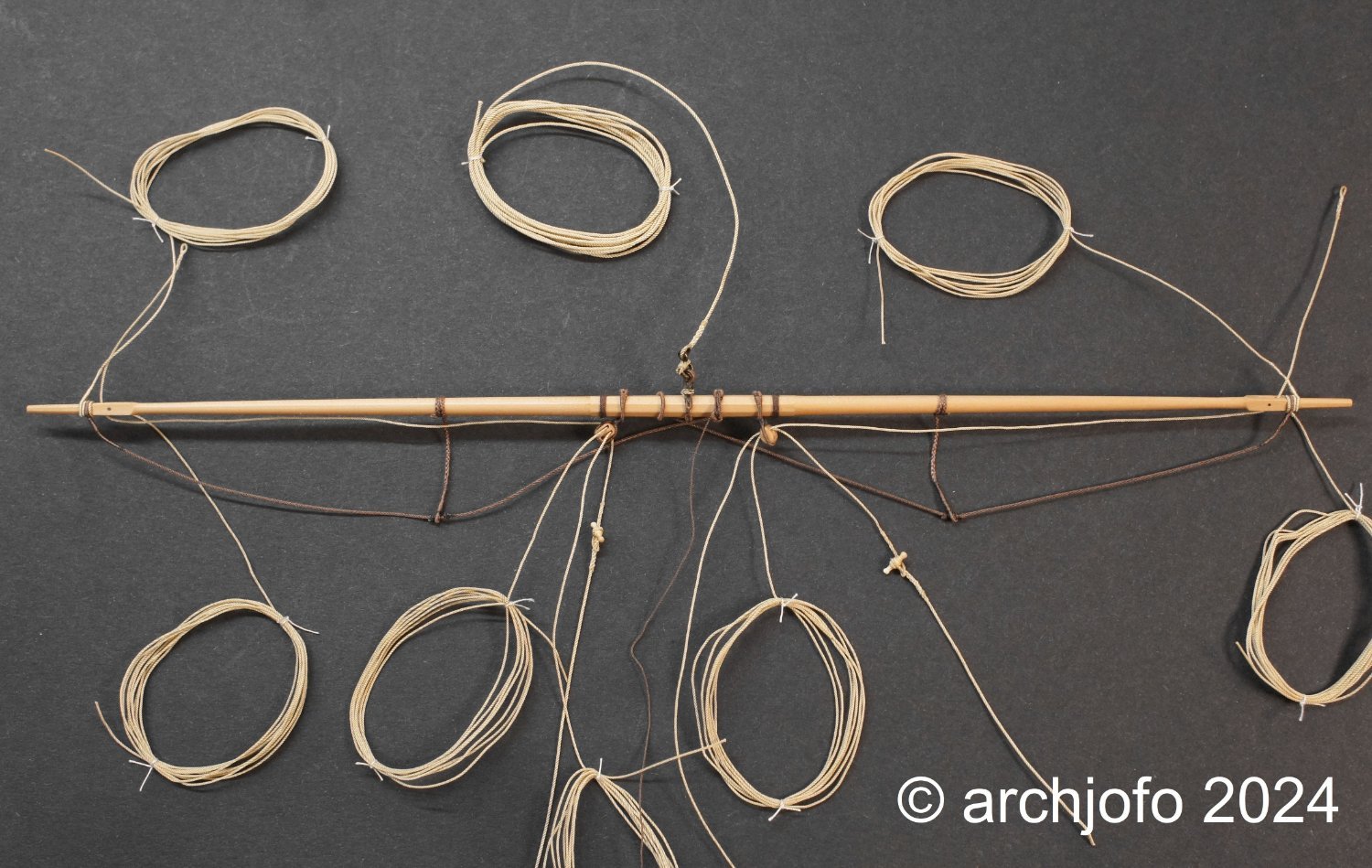
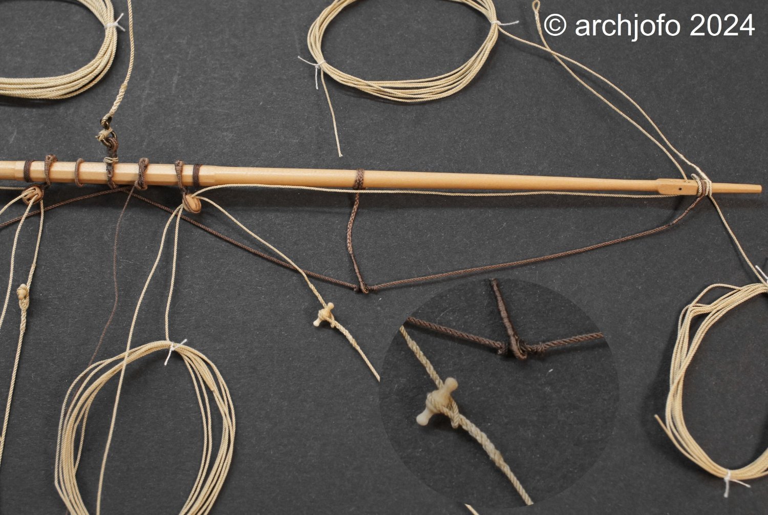
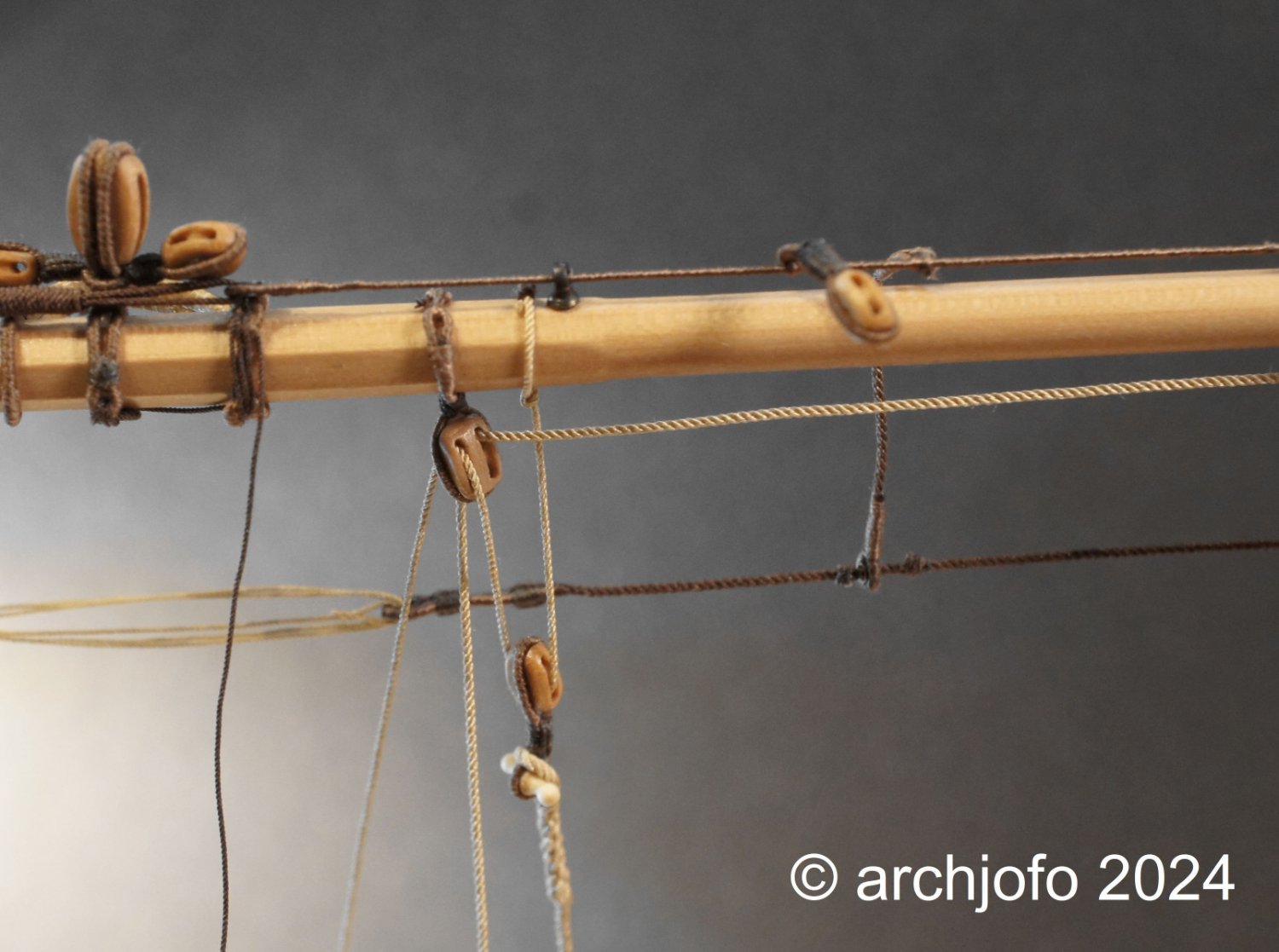
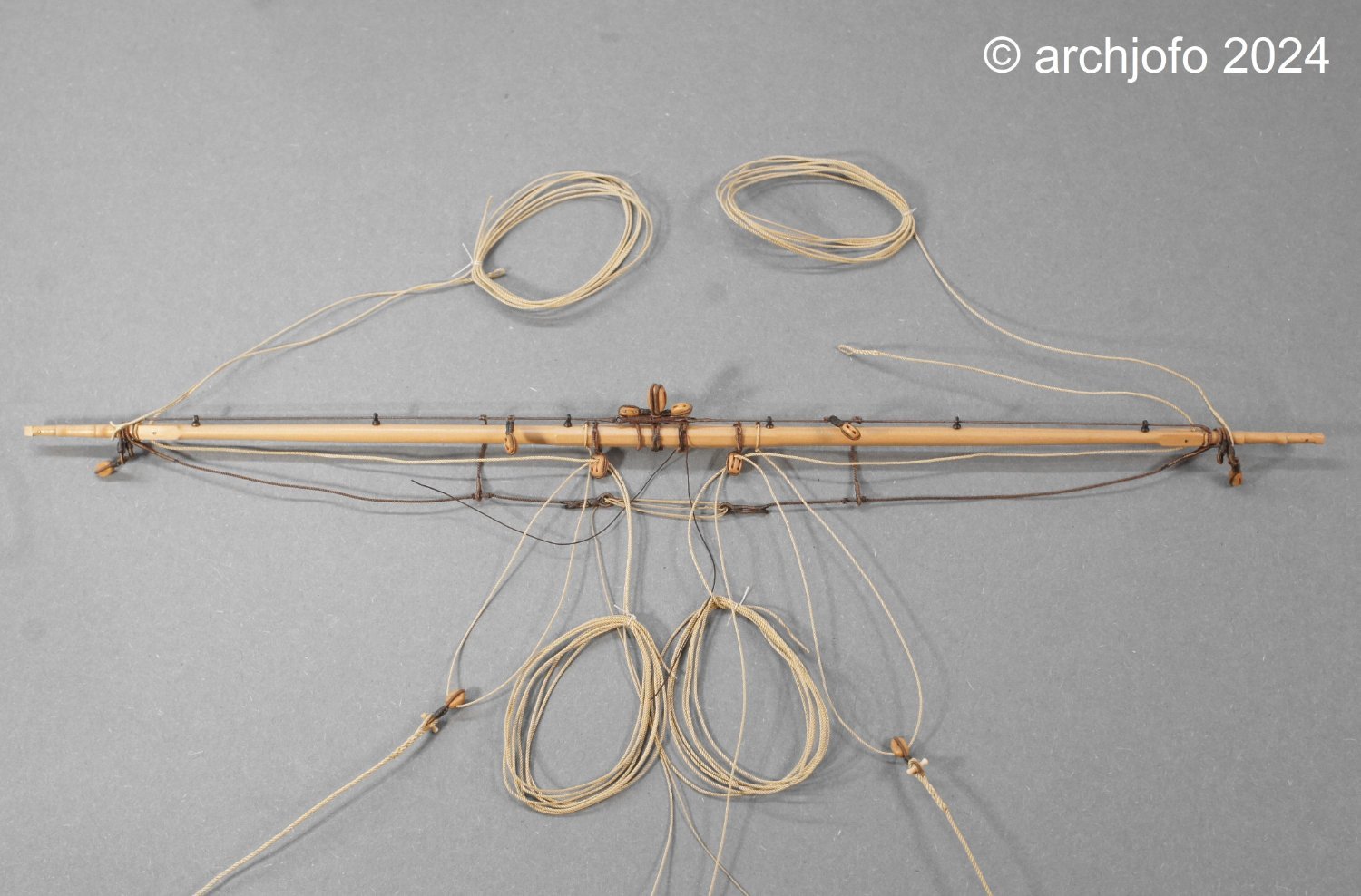
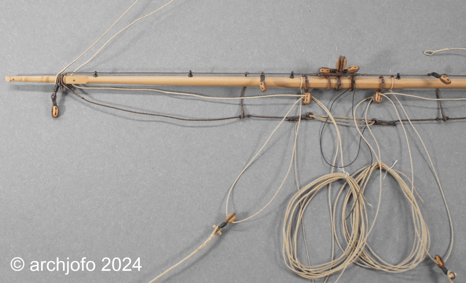
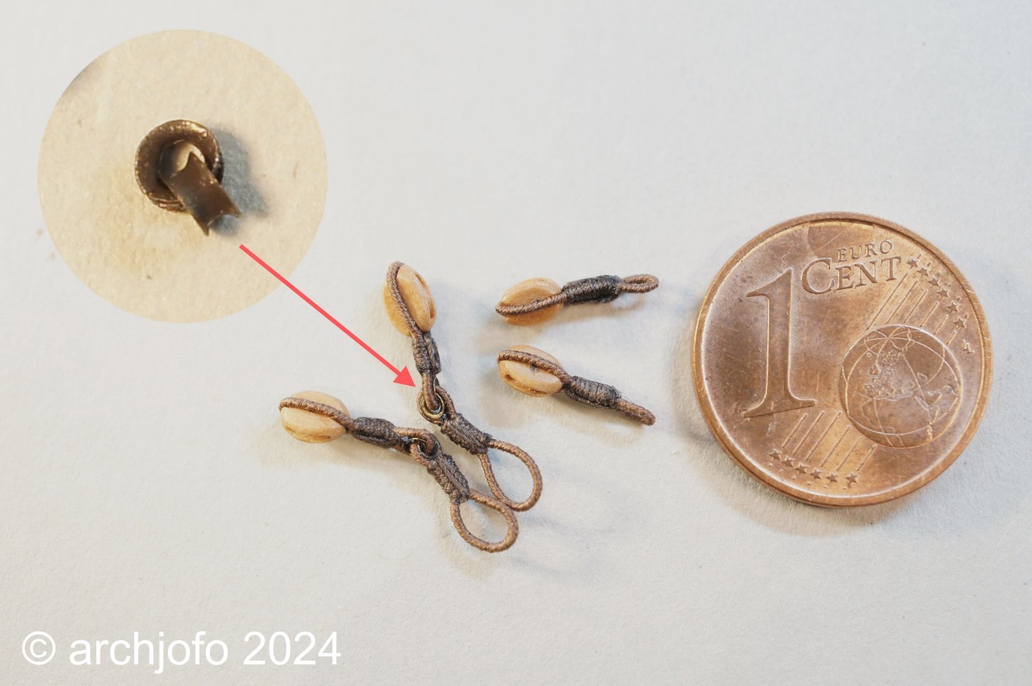
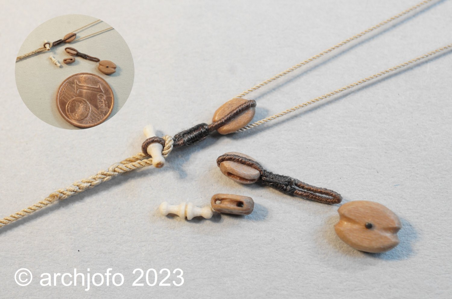
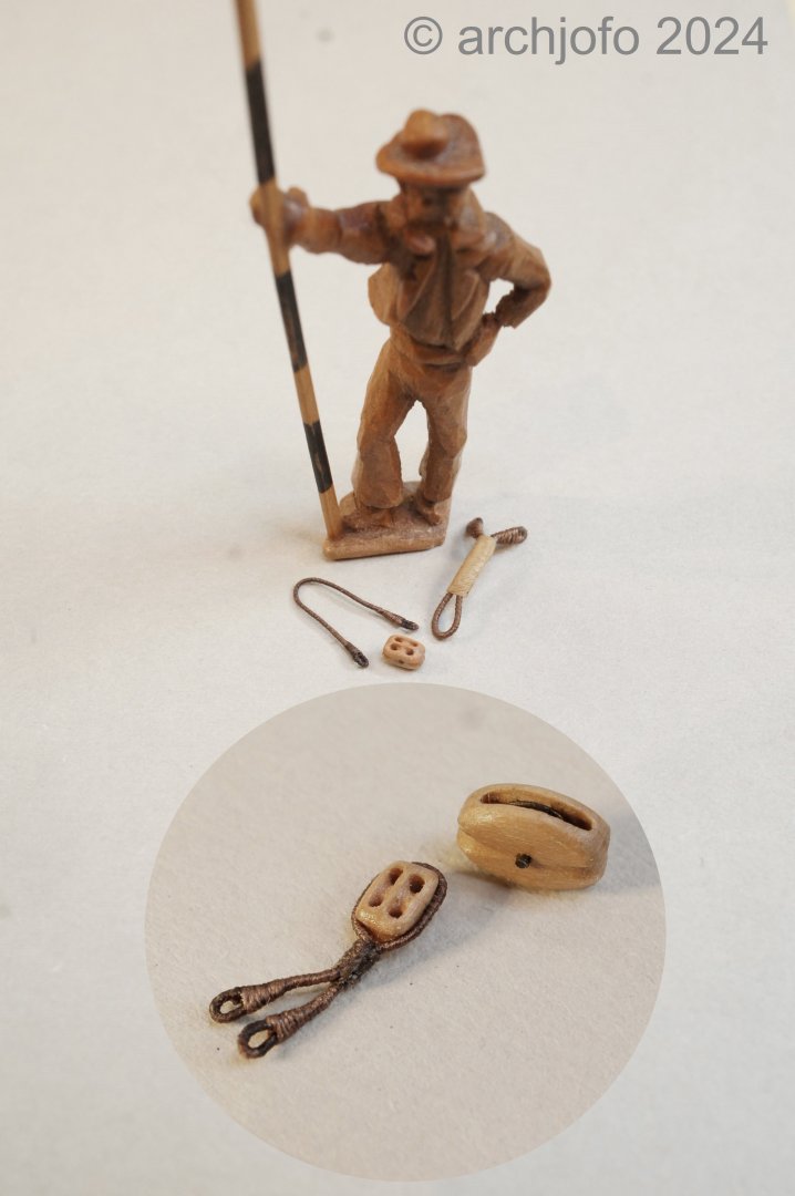
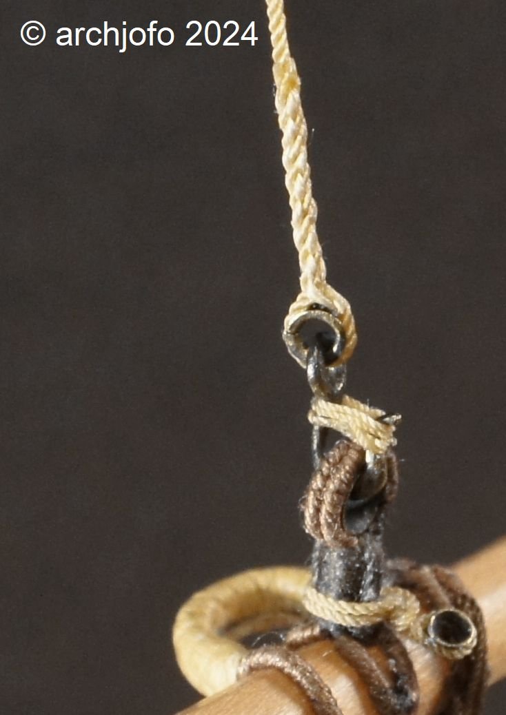
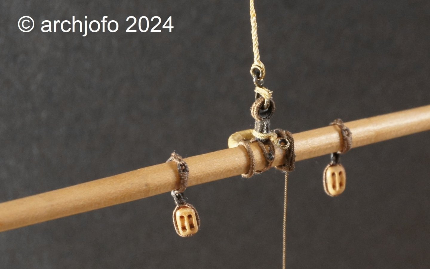
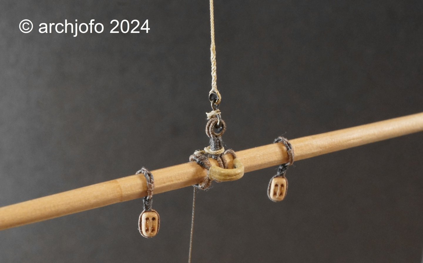
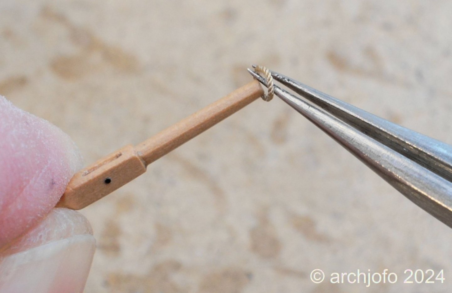
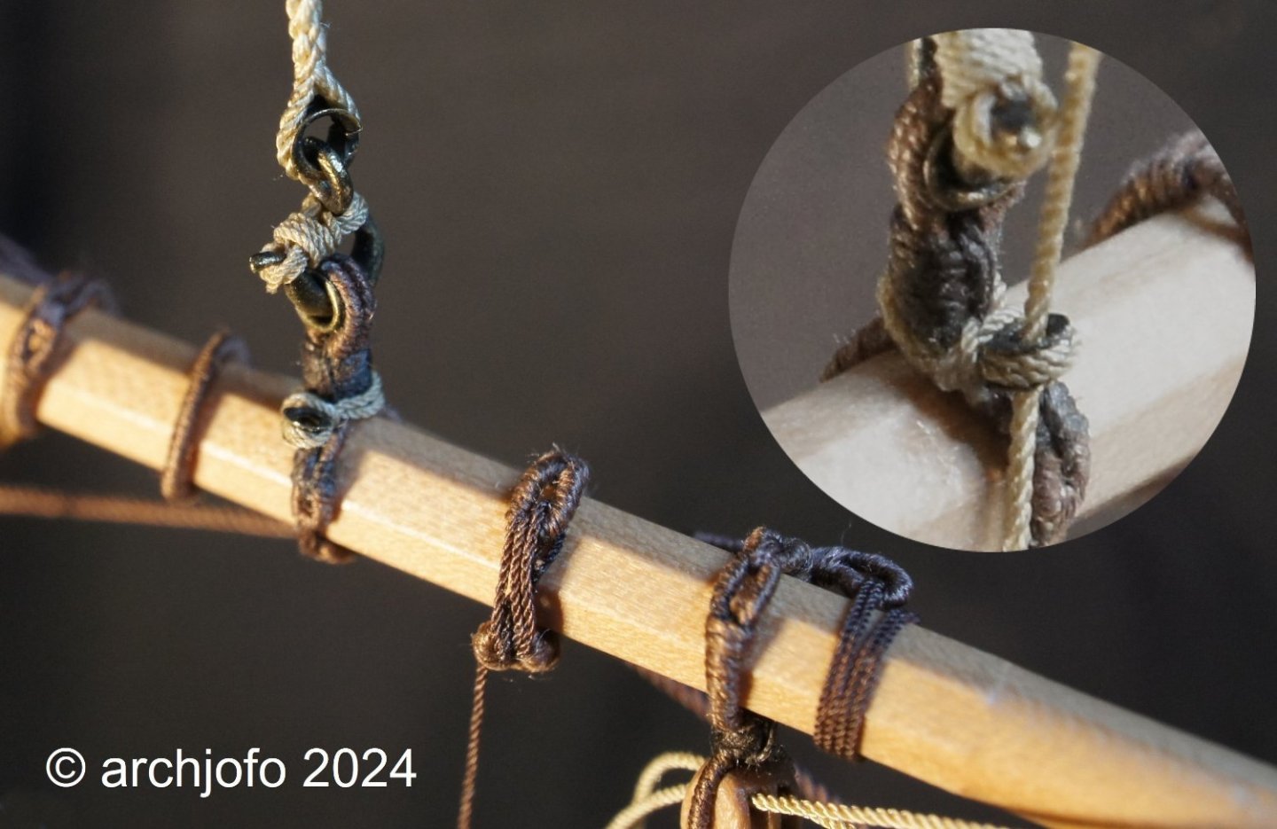
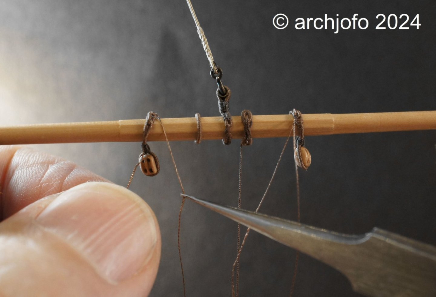
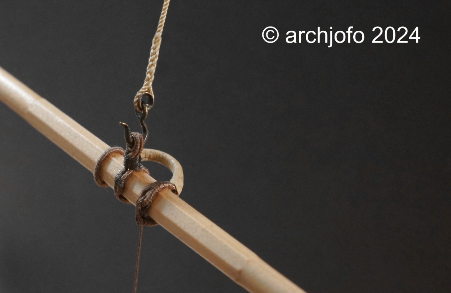
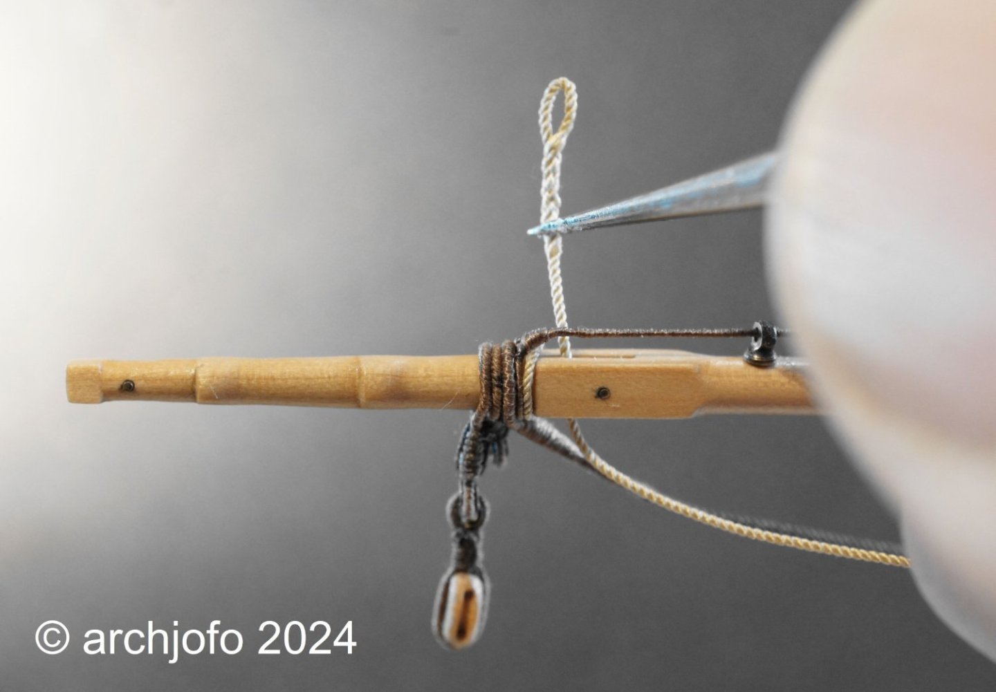
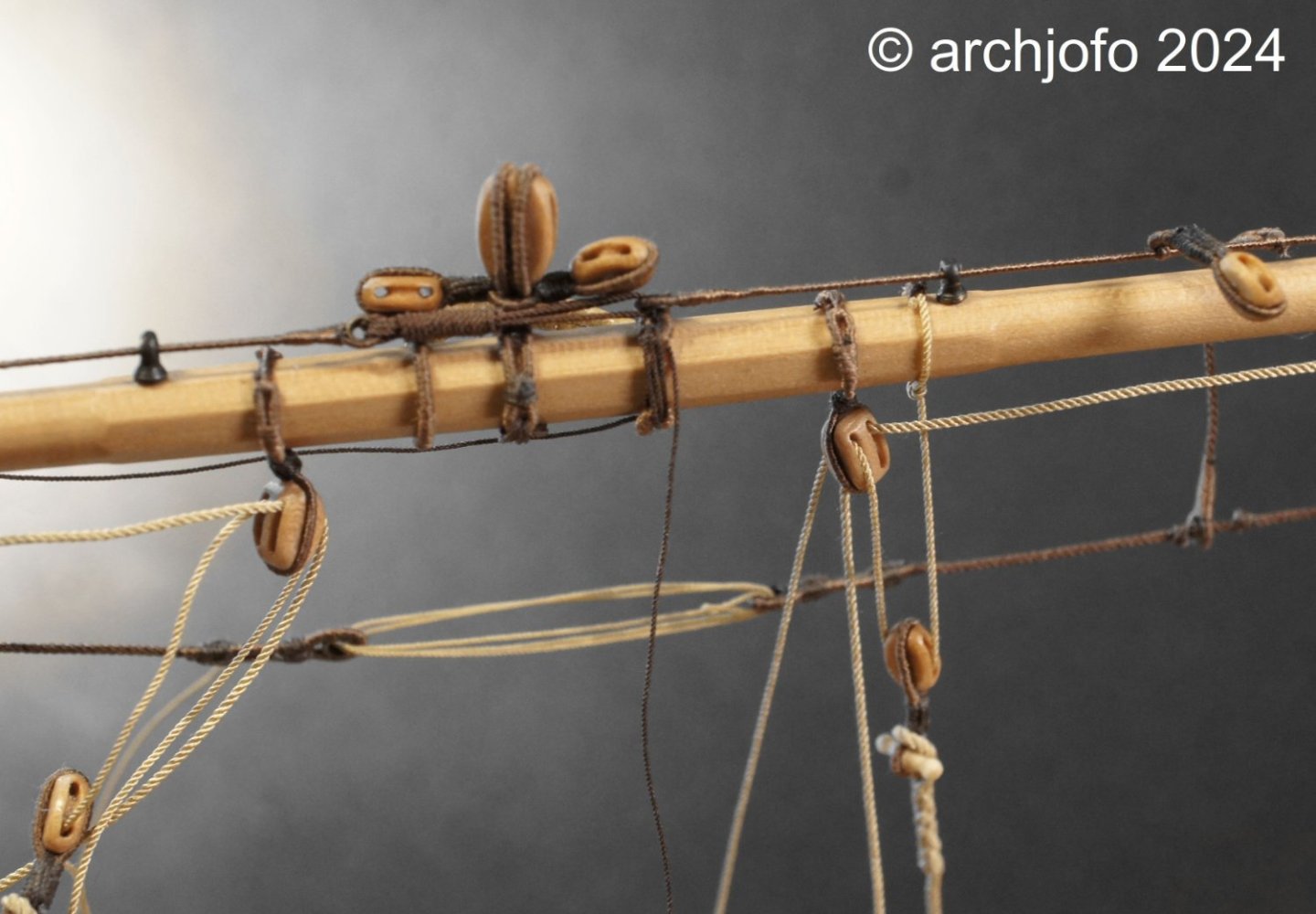
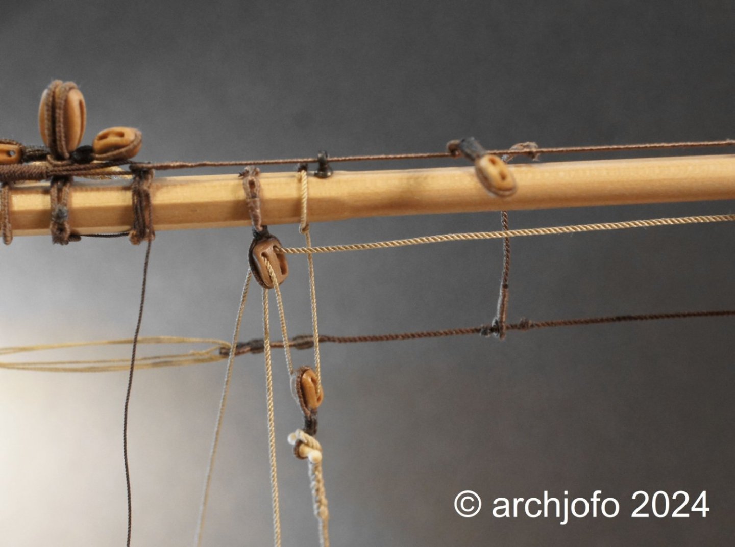
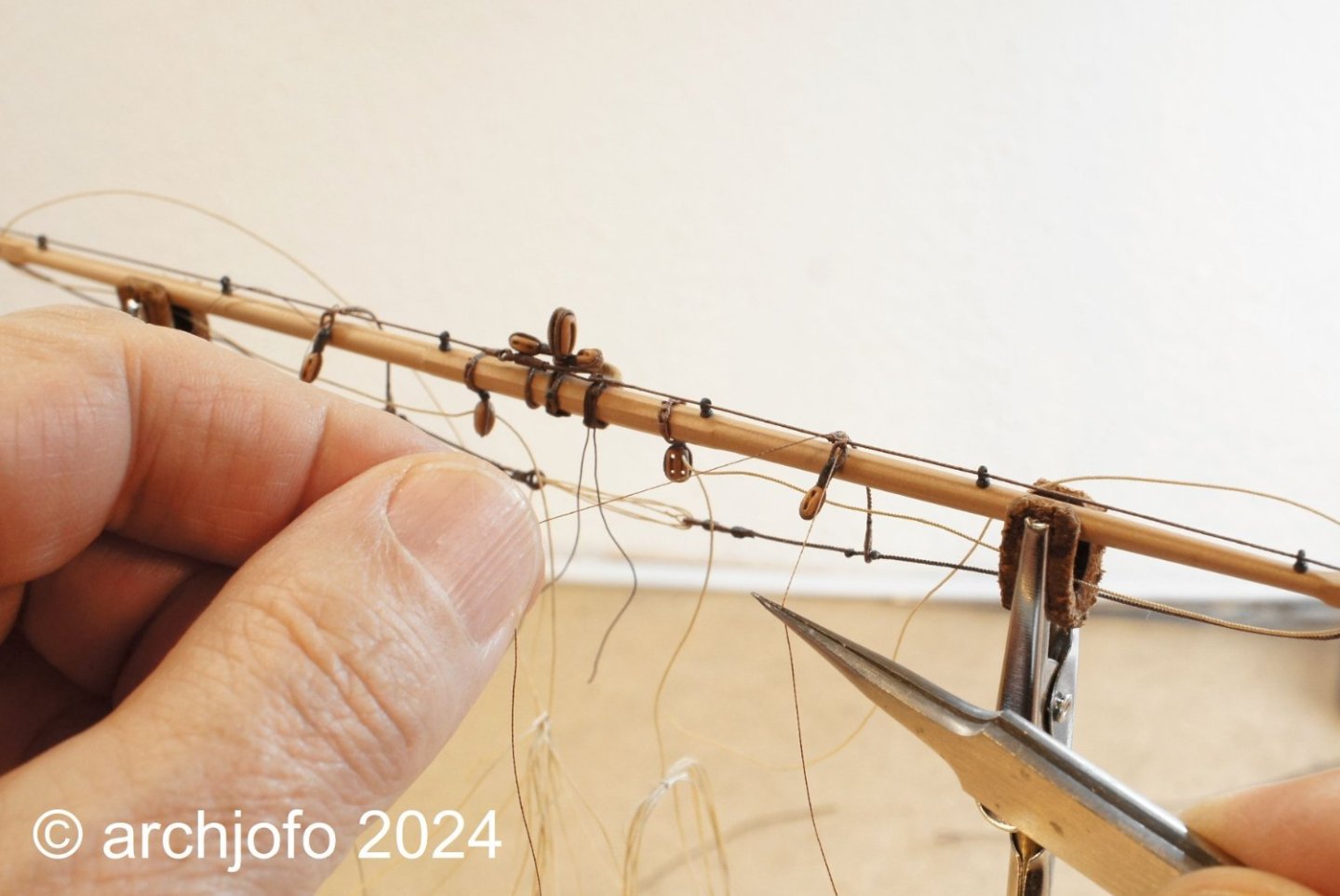
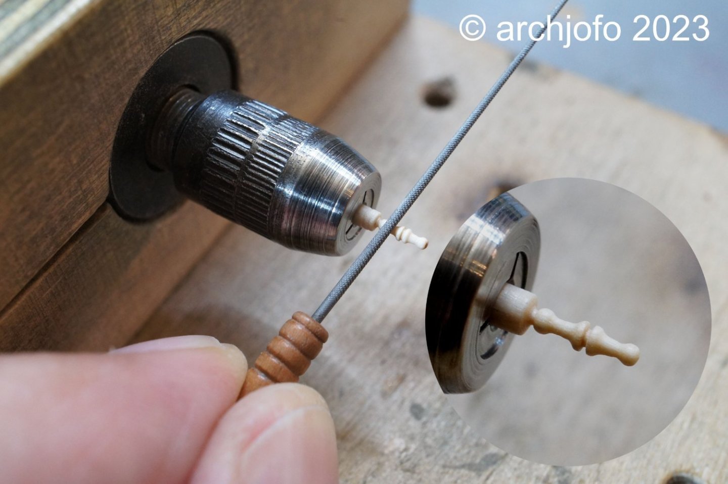
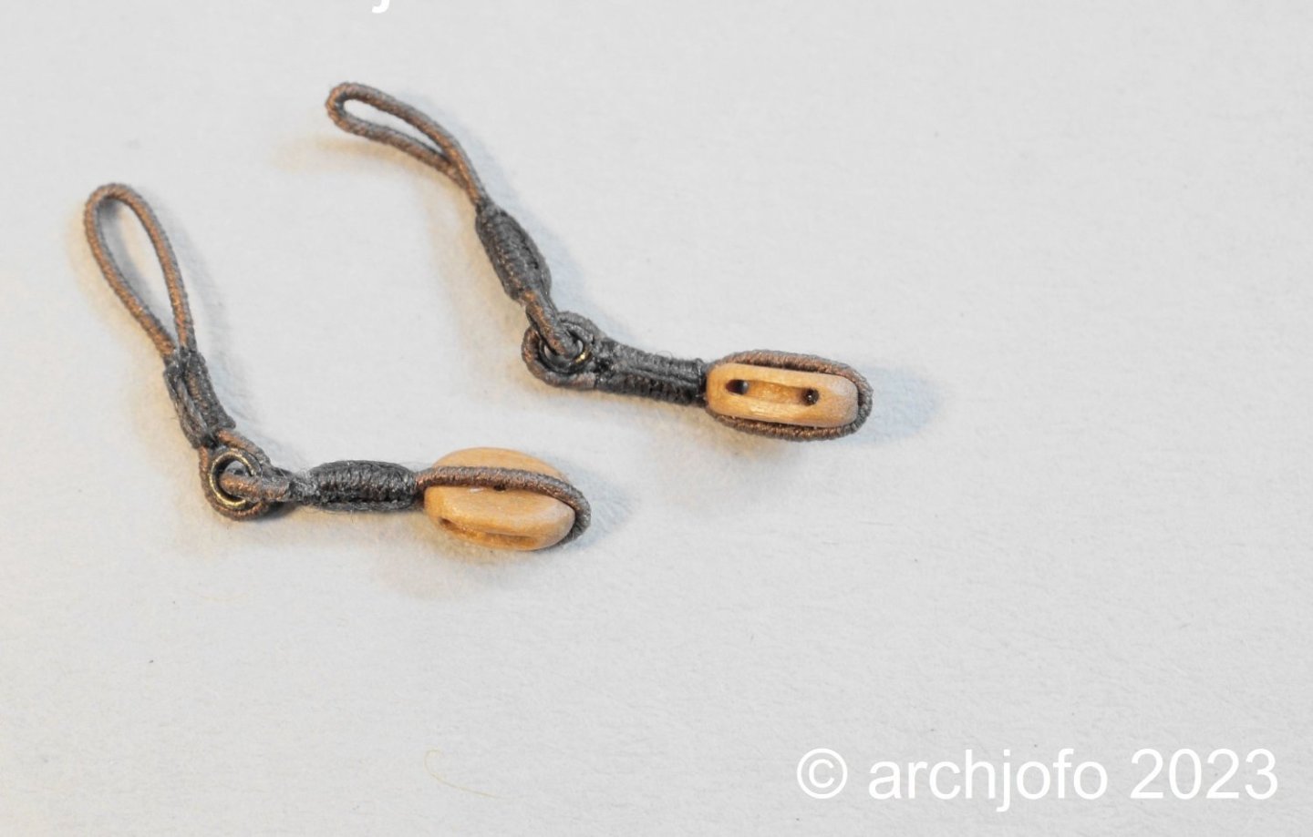
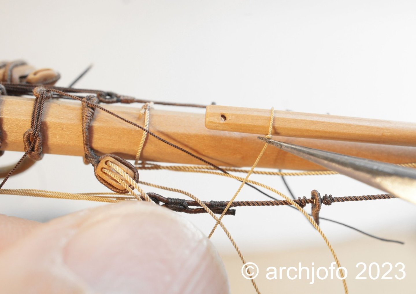
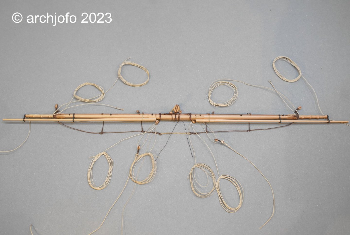
@druxey Hello, I'm glad you like it. Thanks ! I would also like to thank everyone else for the LIKES. Continuation: Equipment of the mizzen topgallant yard – Vergue de perruche After a suggestion from model building colleagues, I secured the mousing of the hook for the tye with a thinner three strand rope with a diameter of 0.15 mm that was specially made for this purpose. We then continued with the quarter blocks (clew lines and sheets), which are among the smallest double blocks on the model. For the block ropes I used ropes with a diameter of 0.25 mm, which were served with silk yarn. The last two pictures show the arrangement of the quarter blocks with the truss already attached. Up soon …
-
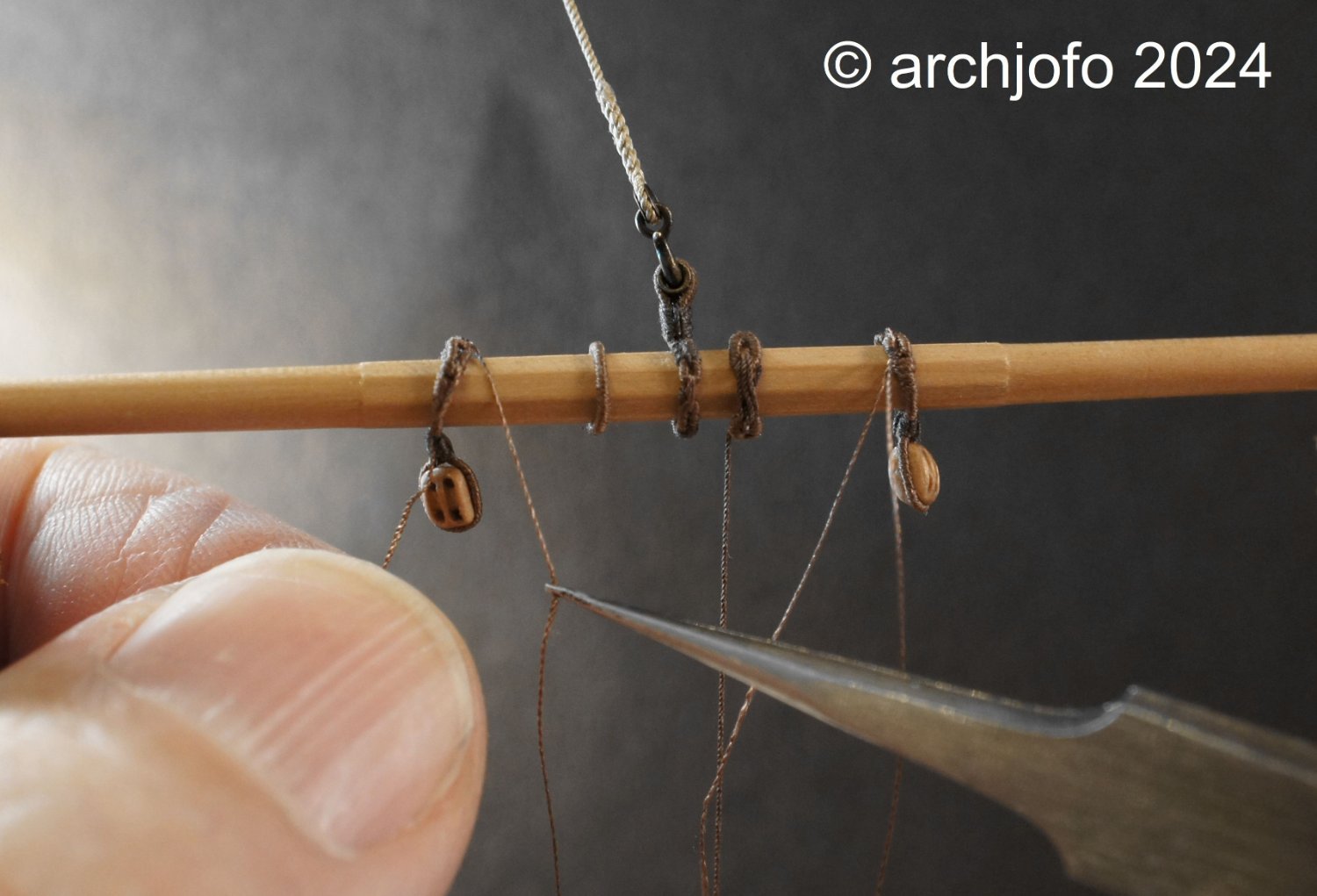
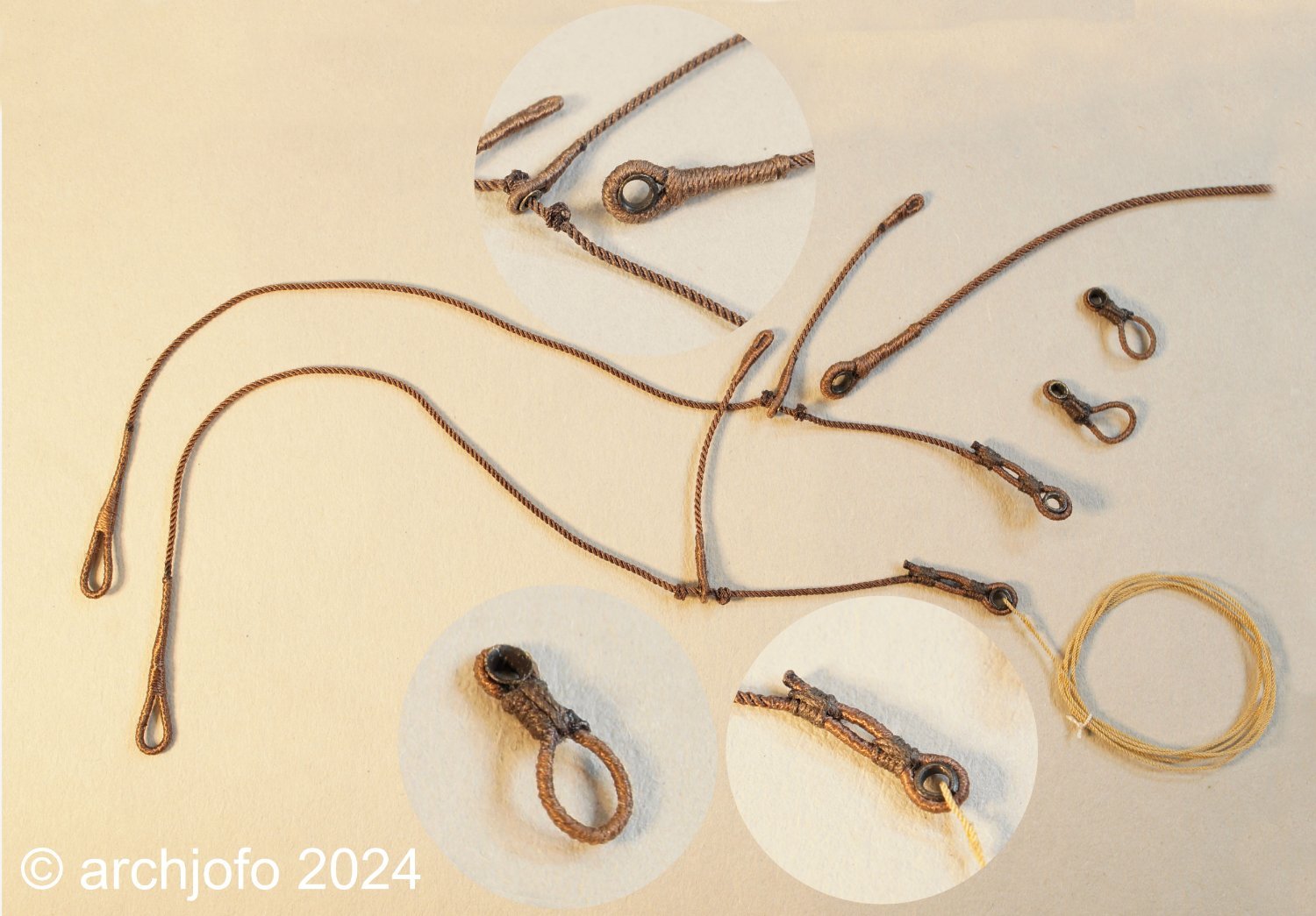
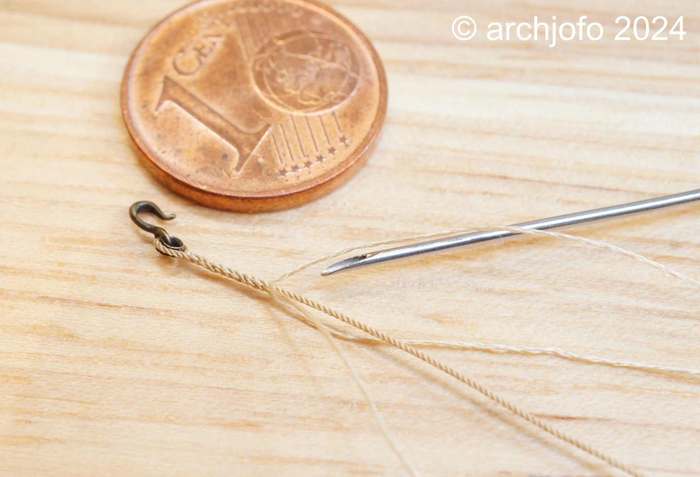
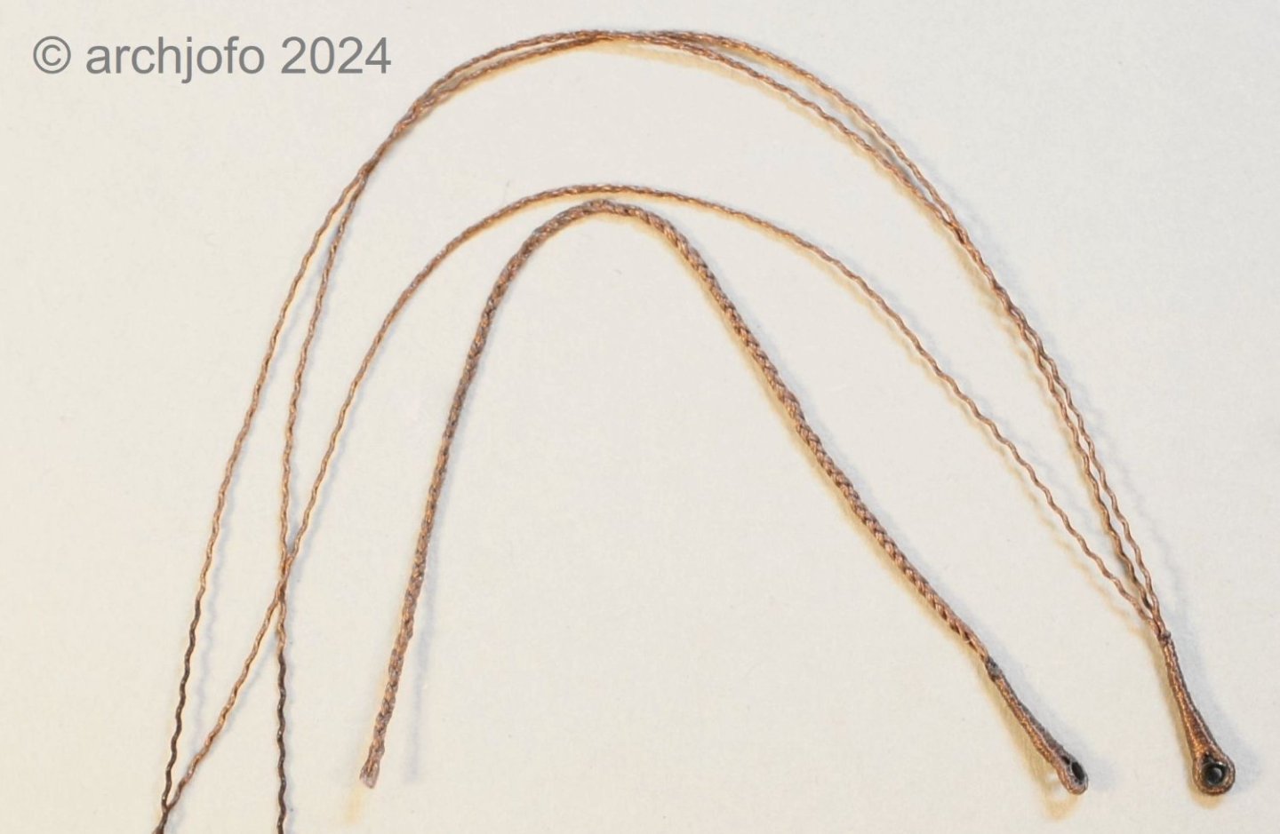
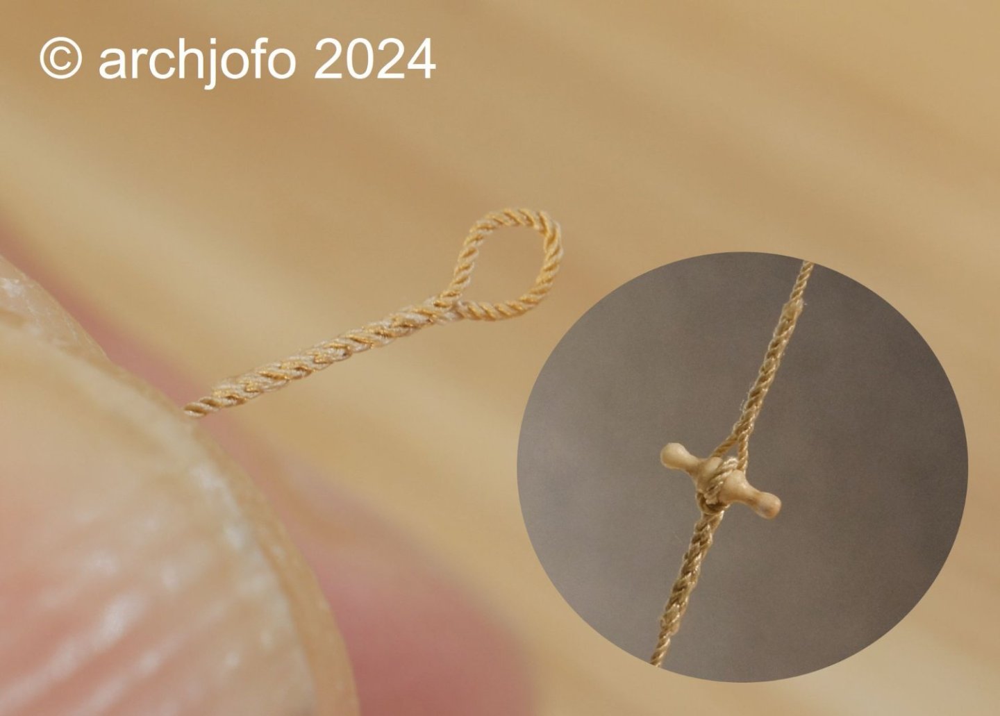
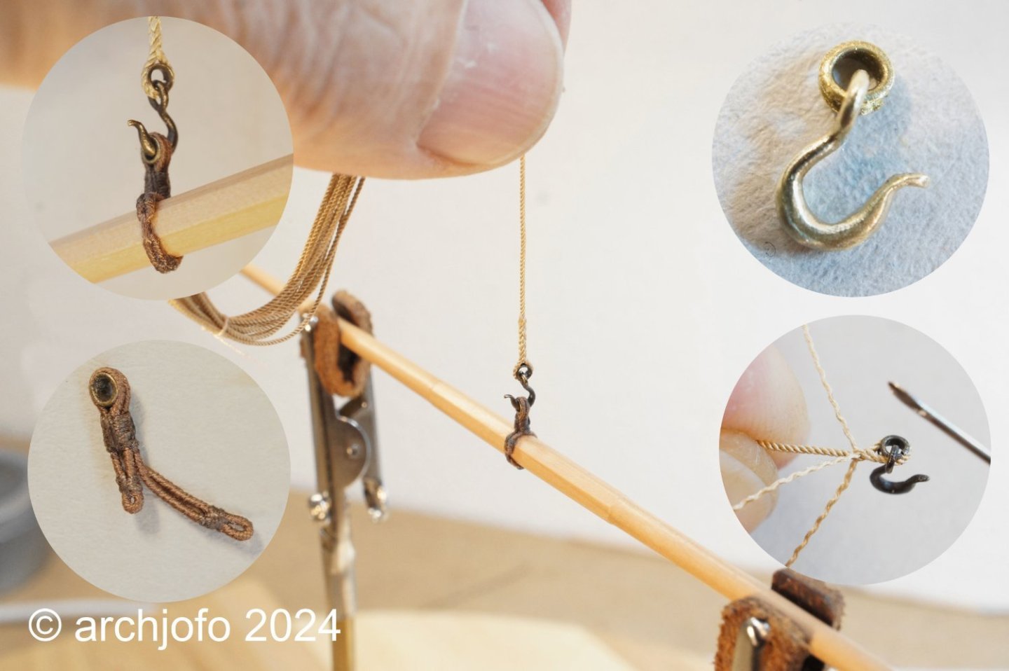
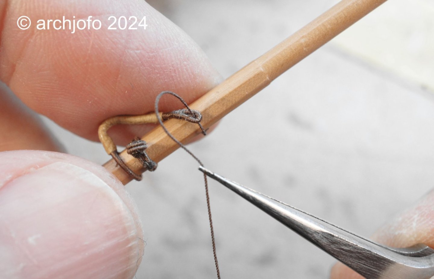
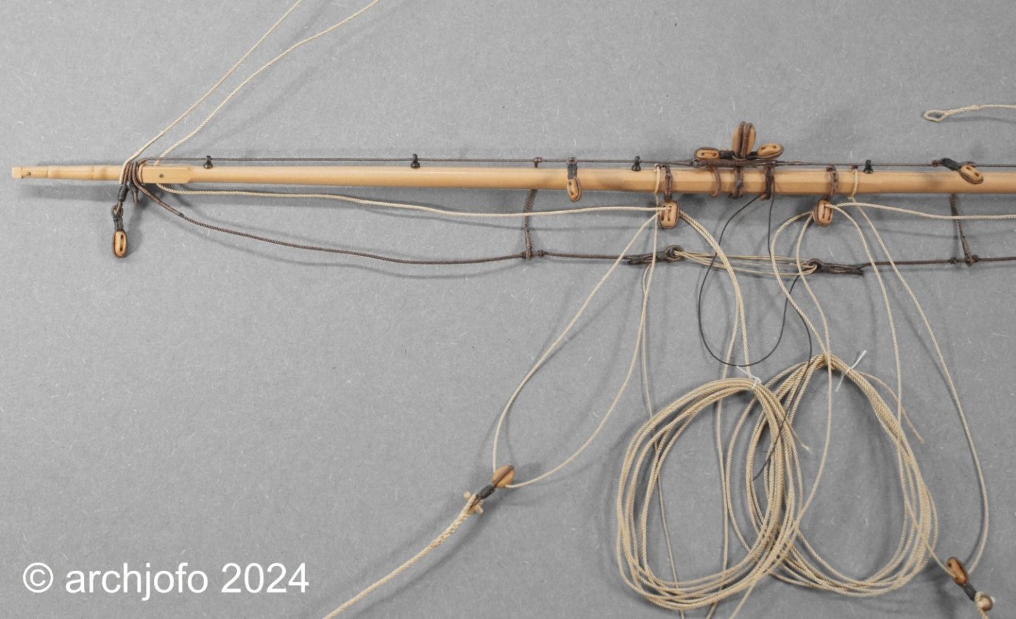
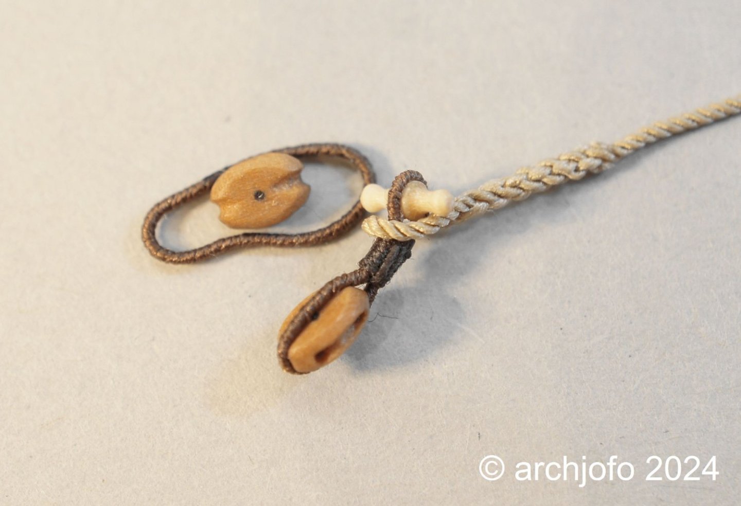
Continuation: Equipment of the mizzen topgallant yard – Vergue de perruche After a short creative break, we continue with the equipment of the mizzen topgallant yard. The equipment and rigging elements basically correspond to those of the fore topgallant yard, but again with correspondingly smaller dimensions. The mizzen topgallant tye is also equipped with a hook. At around 4 mm long, this is even smaller than the hook for the tye of the fore topgallant yard. Of course, the eye splice couldn't be missing either. With a rope with a diameter of 0.35 mm (2x3 Japanese silk thread - rope in the original ø 17 mm) this is a difficult matter, but after some practice it is definitely doable. It just looks better and corresponds to the original design. As already described several times, I use an injection needle as a hollow spike for splicing, with a diameter of 0.8 mm for the thin ropes. In the next picture you can see the mizzen topgallant tye with the double strop and the thimble already tied on to guide the simple clueline. Sequel follows …
-
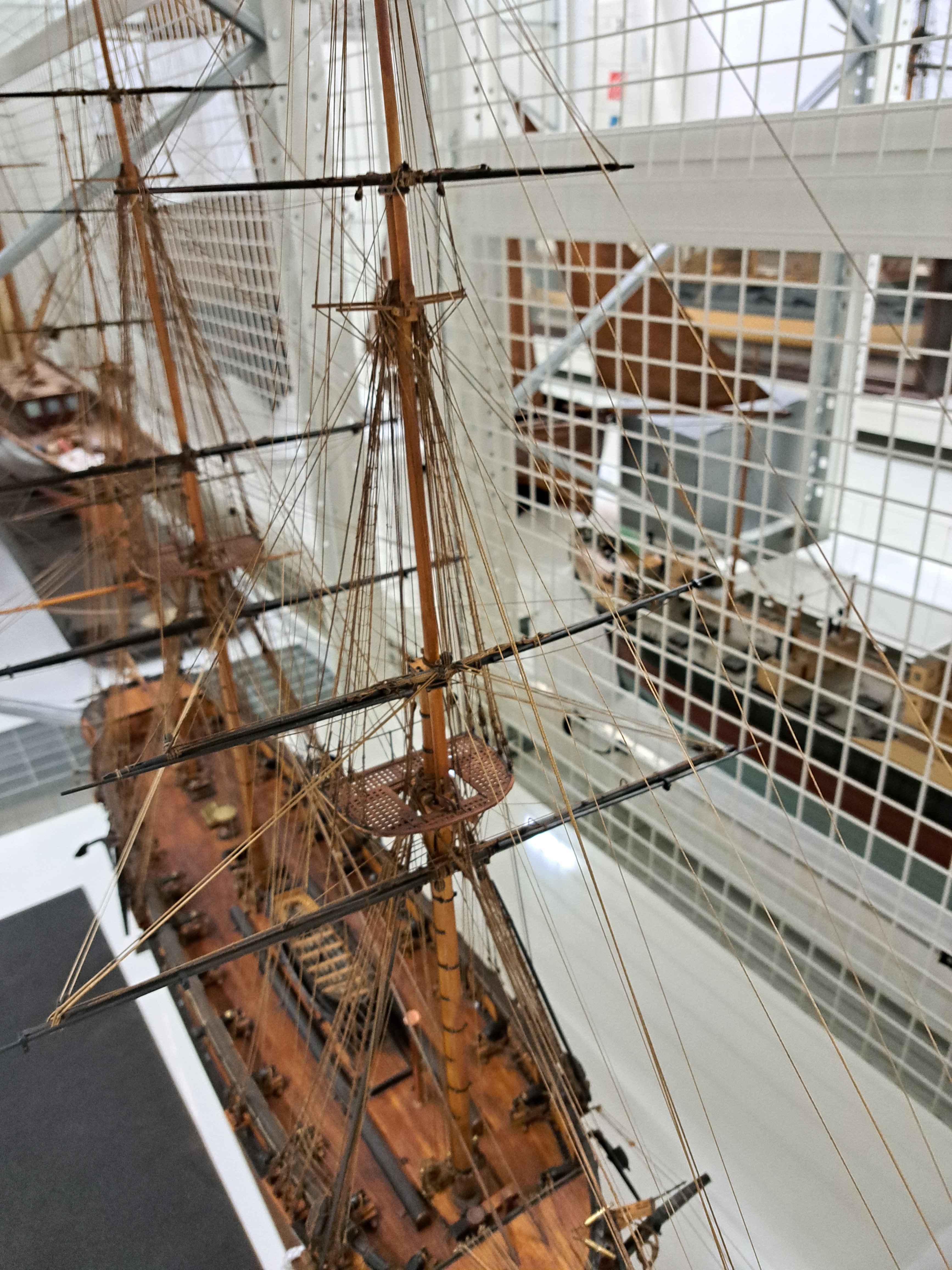
@Gregory @Keith Black Hello, thank you very much for your kind words. Musée national de la Marine in Paris Today I have to get the following off my chest. As you all know, the Musée national de la Marine in Paris reopened its doors some time ago after many years of renovation and modernization. Our forum colleague Eberhard @wefalck reported on this with impressive photos. I actually planned to visit the reopened museum later this year and in particular to view and photograph my "object of desire", the original model of "La Créole", in order to, among other things, to explore unclear details of the upper rigging. After his first visit, Eberhard indicated that he was not sure whether “La Créole” could still be seen in the permanent exhibition. After contacting the museum, I was informed that this was indeed the case and that the "La Créole" had ended up in storage, like many other models. When I asked if it would be possible to take a few photos of the upper rigging (topgallant yards and royal yards), I was referred to the restorers. A very friendly restorer then went to the depot especially for me and took a whole series of pictures of the rigging. Regardless of the fact that these recordings are very valuable for my project, I am shocked by the fact that this beautiful model has now become the victim of a new museum education. Apparently the aim is to reach a wider audience. The German Museum is also apparently following this trend. As I found out, for example, the beautiful 74 model after Boudriot by our forum colleague Robert @tarjack can no longer be seen in the permanent exhibition. Is this the future of cultural-historical and artistic creation? Here is a picture from the depot of the Paris museum, where the "La Créole" will now eke out its future existence alongside many other models. It almost looks like a prison, which makes me a little sad. Previously proudly presented in the permanent exhibition, published with glossy photos, among other things, by J. Boudriot and now in the depot without protection. Hopefully the air in the depot is dust-free. I'm still hoping that one of the restorers will remember the model and fix the already partially dilapidated rigging.

-
@Thukydides Hello, Certainly I can state this with absolute certainty for the French. I found this in Contemporary Technical Literature from 1829 by F.A. Coste. As far as I know, it wasn't just the French, the English also had this type of stirrup.
-
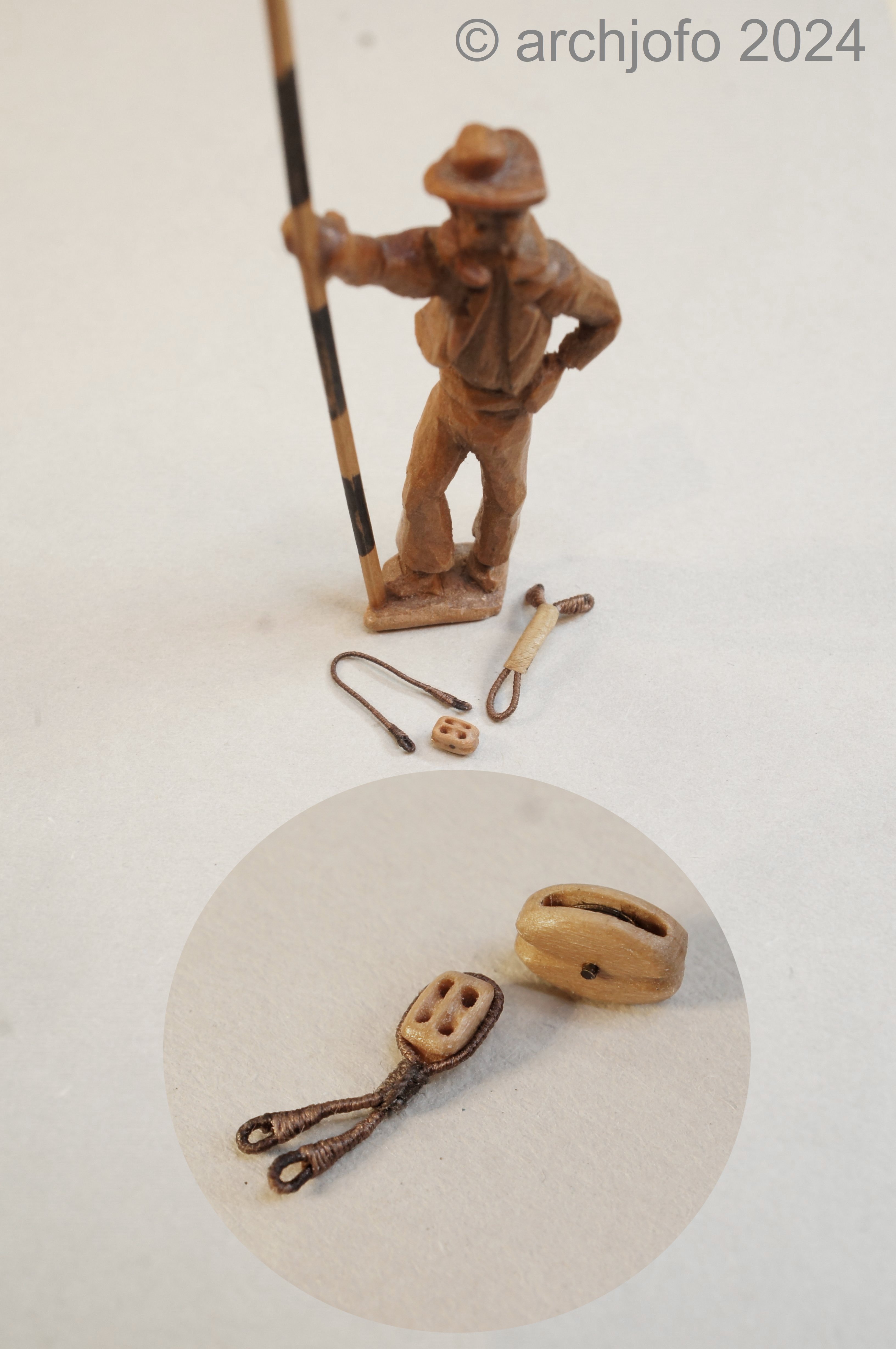
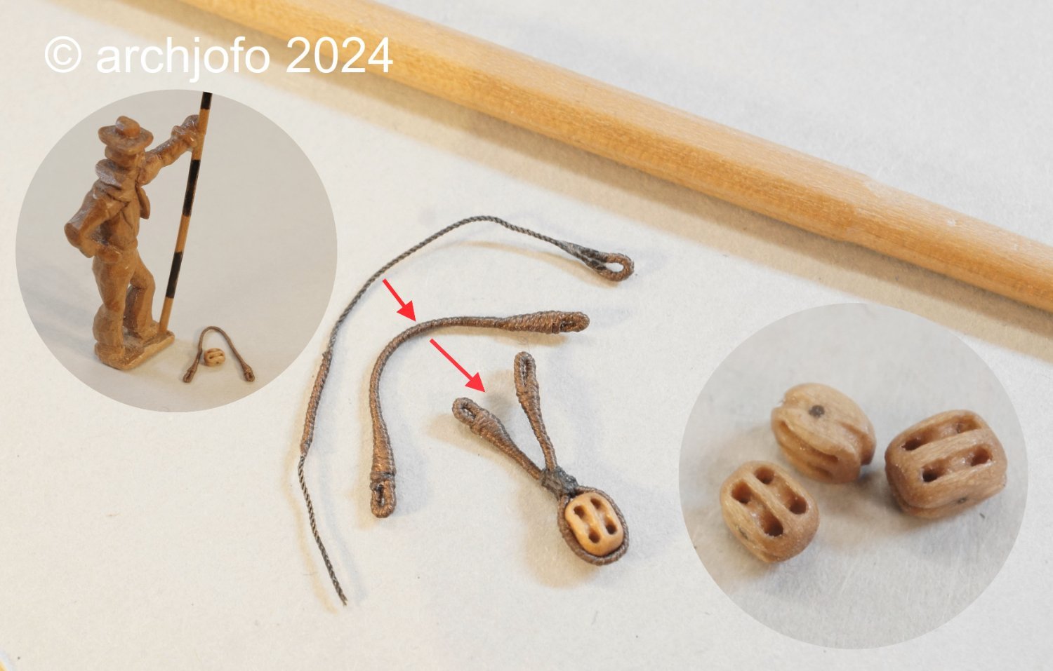
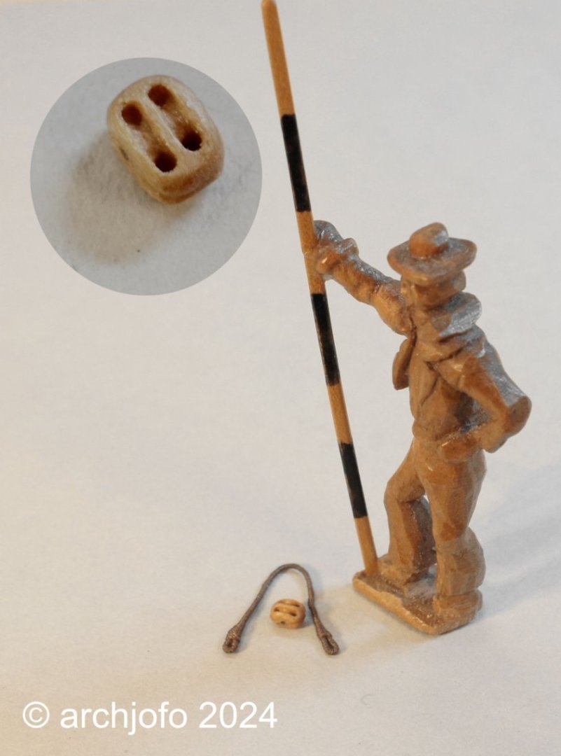
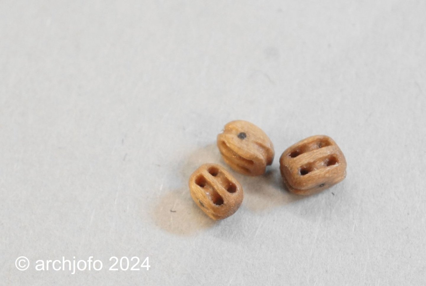
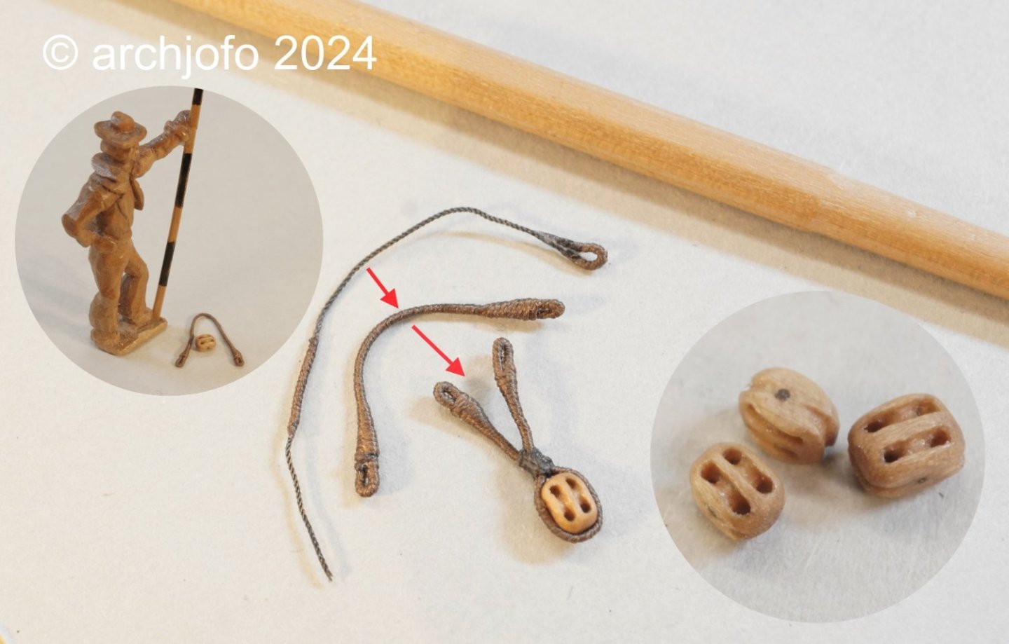
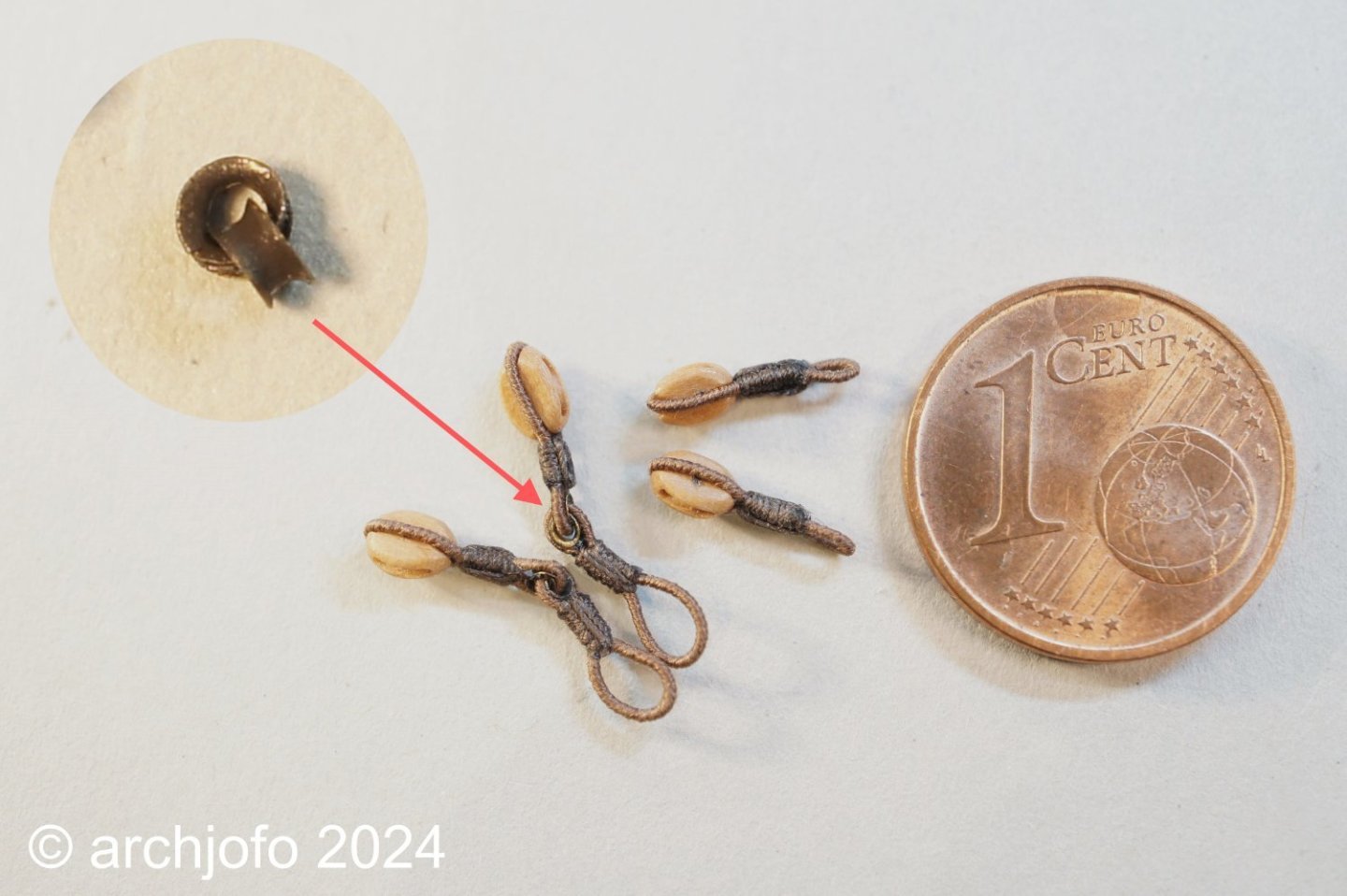
Continuation: Equipment of the fore topgallant yard – Vergue de petit perroquet As announced a long time ago, I started to equip the fore topgallant yard. In principle it is the same rigging elements and accessories as the main topgallant yard, just with reduced dimensions. In this respect, I don't want to repeat myself and let the pictures speak for themselves. The double blocks for the royal sheets and the single cluelines are also a little smaller. Here is a direct comparison of a quarter block for the main top gallant yard with those of the fore top gallant yard. Unfortunately, at this size you can already see some irregularities. In the next photo I show, among other things: an already made strop for a double block with my scale man, which I've been neglecting a bit lately. Actually a loyal companion at the model building yard for more than 10 years now. And here's another picture of the stirrups. On the one hand you can see the unraveled rope and on the other hand the finished braided plating. The sheets are connected to the cluelines in the usual way when no sails were attached. Finally, here is a picture of the entire fore topgallant yard, but still without lifts. Sequel follows …


-
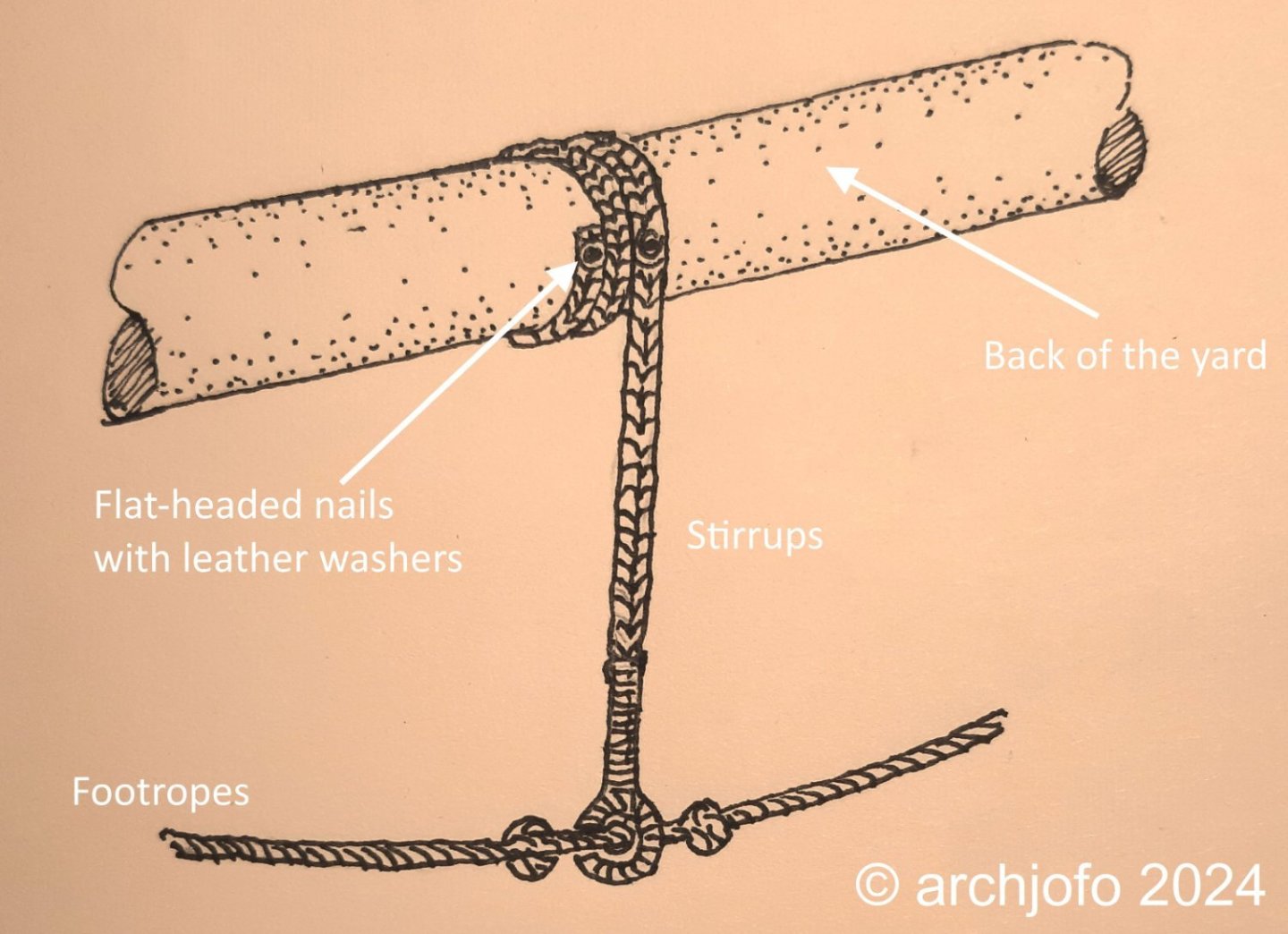
Hello, Based on Eberhard @welfalck's advice and further consideration, this seems to be the better and probably correct solution for attaching the stirrups. The reverse arrangement ensures better drainage of rainwater. I have now also found an illustration of this in "Rundhölzer, Tauwerk und Segel" by K. Schrage.
-
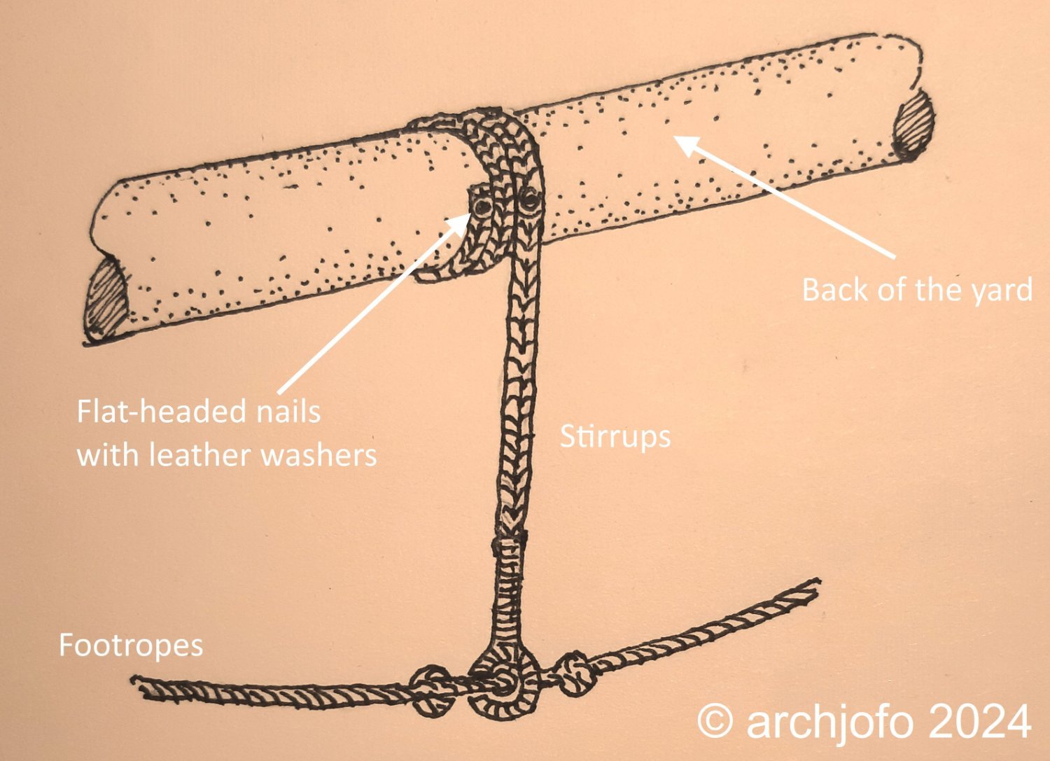
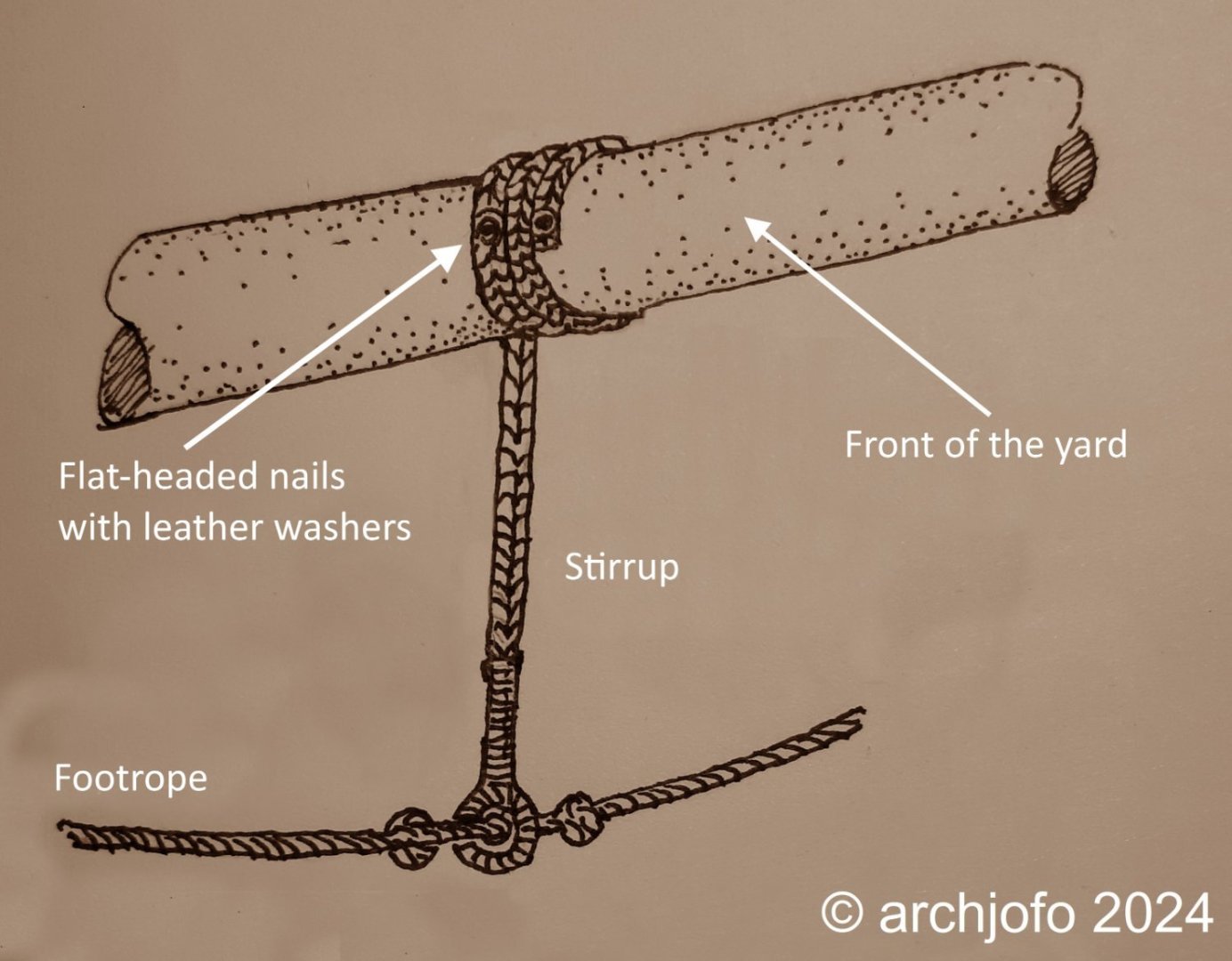
Hello dear colleagues, I wanted to provide an additional explanation about the braided stirrups. In various publications I was able to read how the braids were looped and secured around the yards, but I have not yet found a picture of it. According to these descriptions, I implemented it for my model at the main topgallant yard and now quickly made a drawing at Eberhard's @wefalck request. I think it might have looked like this: Of course I can't be absolutely sure about this.
-
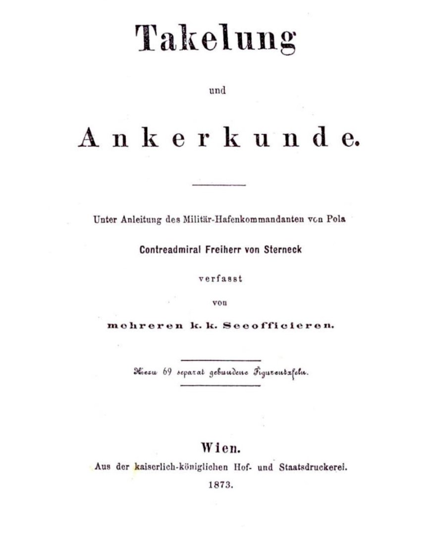
@albert Thanks for your interest and the nice comment. @giampieroricci Hello, This illustration is from the book “Takelung und Ankerkunde” by Freiherr v. Sterneck, published in 1873. Can be downloaded as a PDF from Google Books. This is not quite the time of my corvette, but in conjunction with descriptions from contemporary French specialist literature, these depictions are often a good starting point.
-
Hello Jerry, as explained earlier in my report, the topgallant yards and the royals of my model do not receive any jackstays. In the first years of jackstay use at the beginning of the 19th century, only the lower yards and topsail yards were equipped with jackstays. It was only in later years, around the middle of the 19th century, that jackstays were also used in the upper yards. I think the illustrator only turned the jackstay eyes a little so that they could be recognized as such.
-
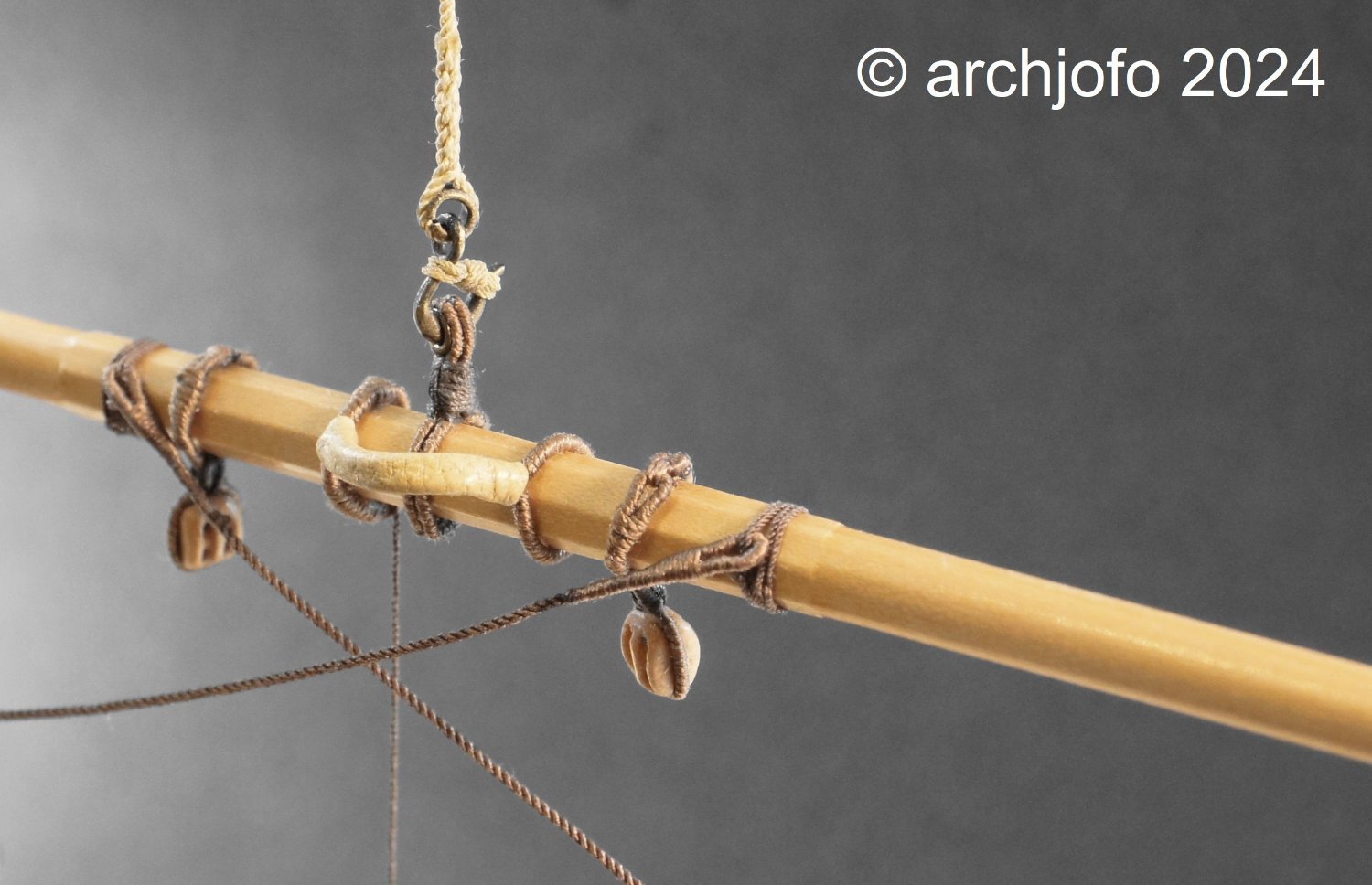
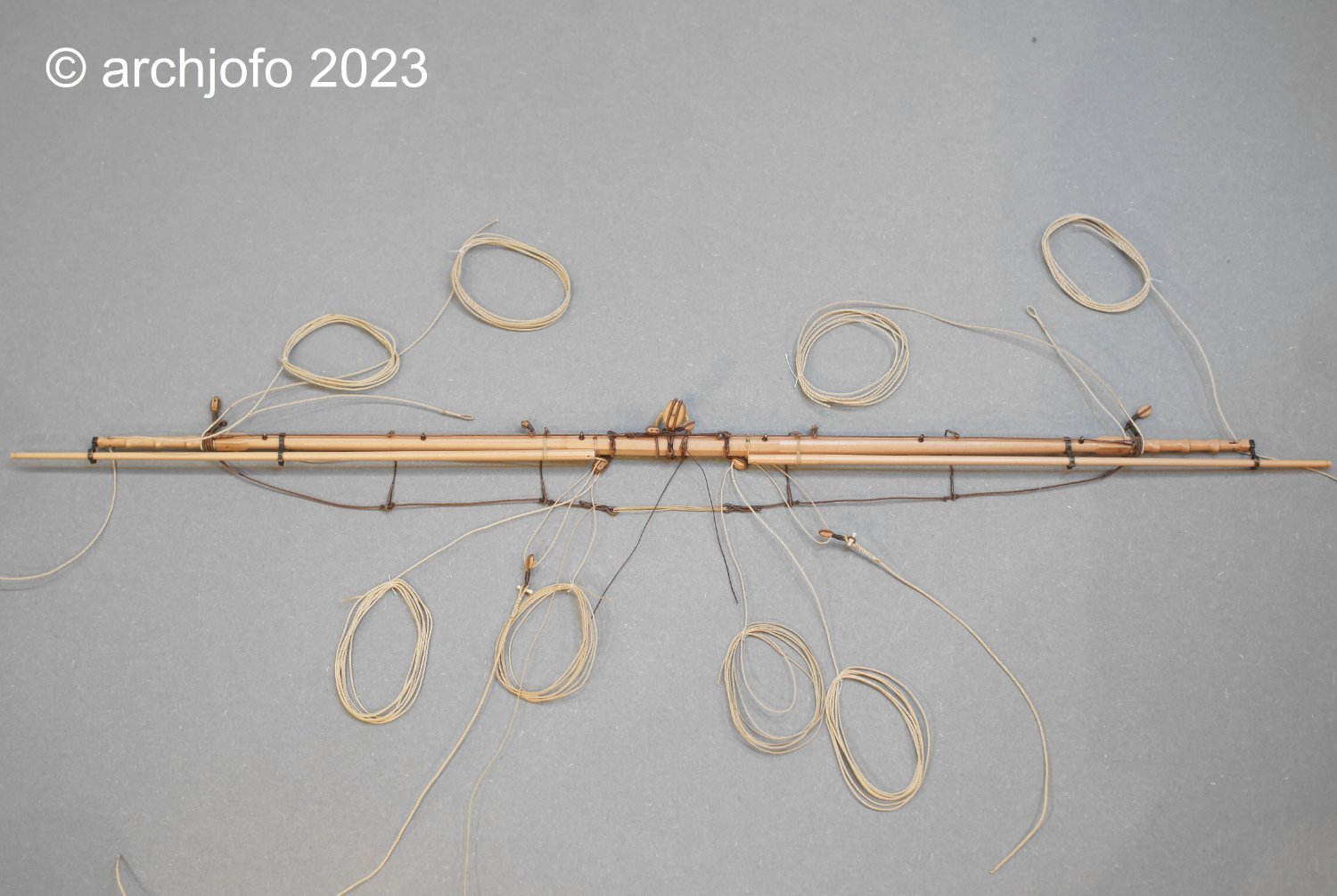
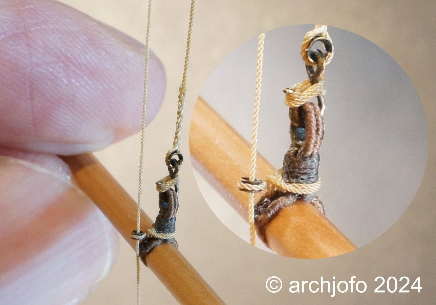
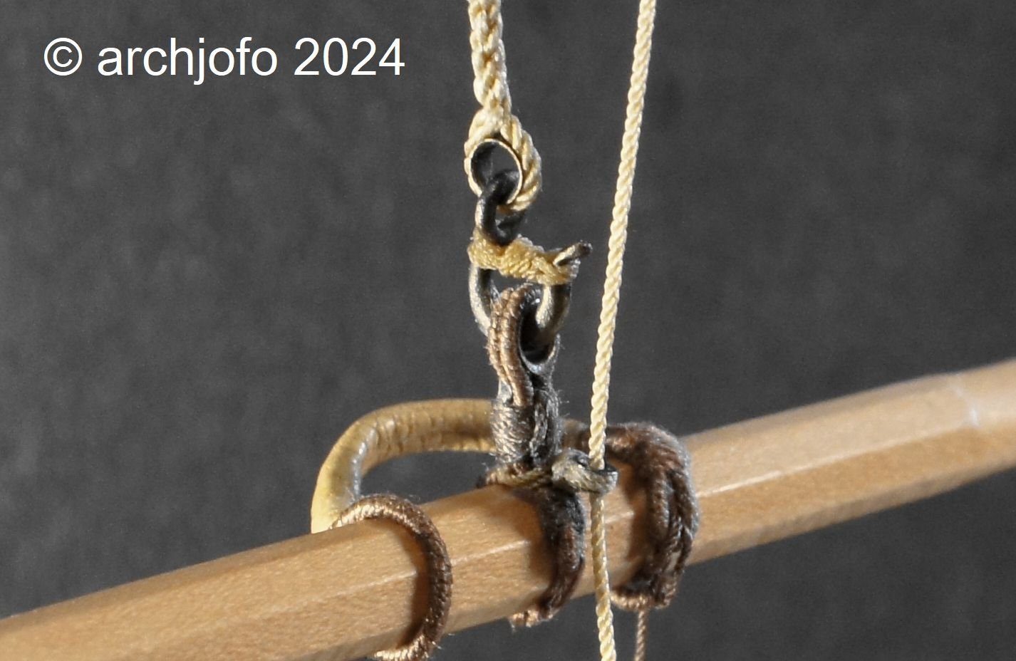
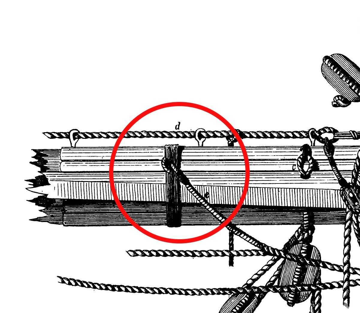
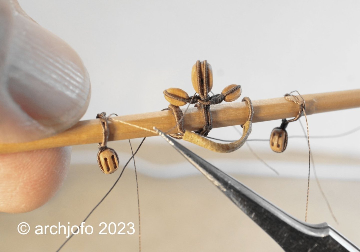
@druxey @Bruma @jdbondy @shipman @giampieroricci Hello friends, thank you very much for your interest in my build report and for the kind words. Also many thanks to all of you for the many LIKES. Continuation: Equipping the main topgallant yard - Vergue de grand perroquet Once I had clarified the details for the footropes with the stirrups, it was time for the implementation. Thanks to the corresponding preliminary work on a test piece, the stirrups were attached to the yard quickly and without any problems. Before the eye splices of the footropes could be pulled over the yardarms, the prepared grommets were first put on as chafe protection. When attaching the footropes in the center of the yard, I used the following example as a guide. Source: Freiherr v. Sterneck, "Takelung und Ankerkunde", 1873 This is what the realization for the model looks like: I have now also made the mousing to secure the hook for the tye: The simple buntlines were guided in thimbles at the topgallant yards of the French corvette. These buntlines branched out in the lower area onto two ropes, which were attached to the leeches of the sail. I therefore attached a thimble directly to the tye, as seen on the original Parisian model. The clewlines for the topgallant sails were normally connected to the clews by means of toggles. Without sails, the clewlines are connected directly to the topgallant sheets. The single-guided lifts, the braces attached directly with eye splices and the aforementioned sheets complete the equipment of the main topgallant yard. These ropes have a diameter of ø 0.25 mm and served eye splices for laying on the yardarms. The last two pictures give an overview of the main topgallant yard with all equipment elements and ropes. I will continue with the fore topgallant yard. More about that soon ...


-
Hello, the rigging with the sails looks very realistic. A really very nice model.
- 399 replies
-
- 3
-

-
- cutty sark
- revell
- (and 2 more)
-
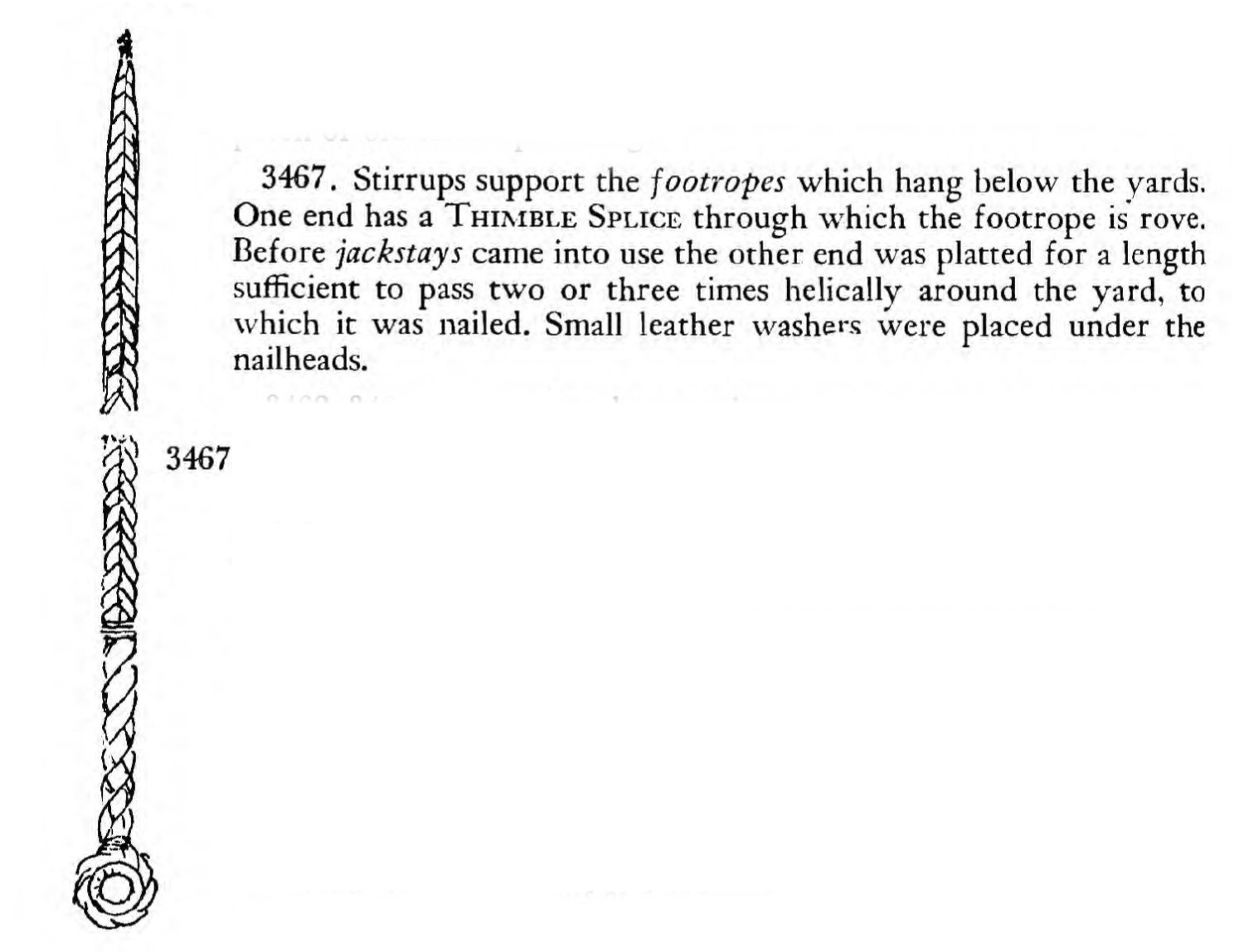
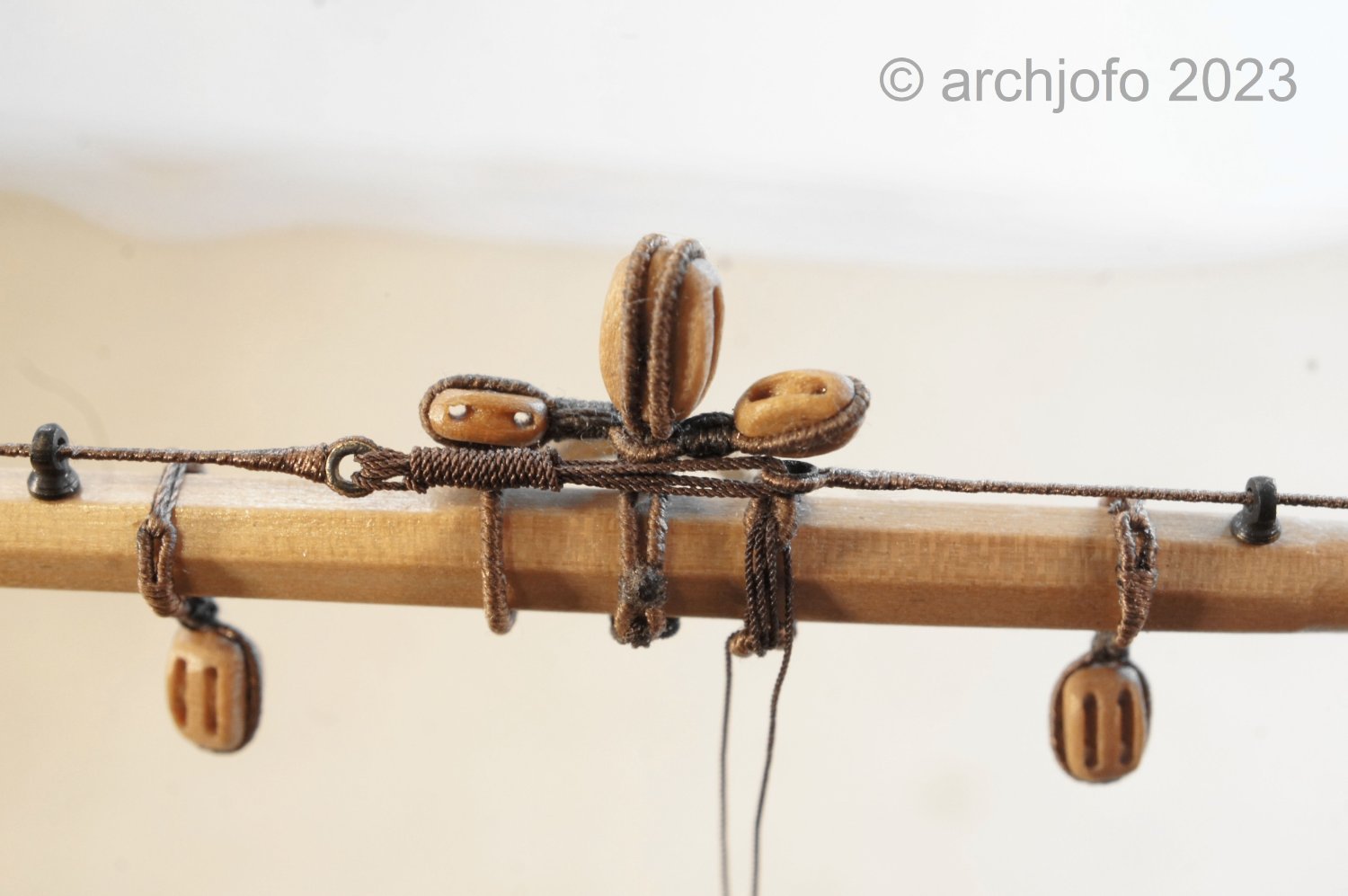
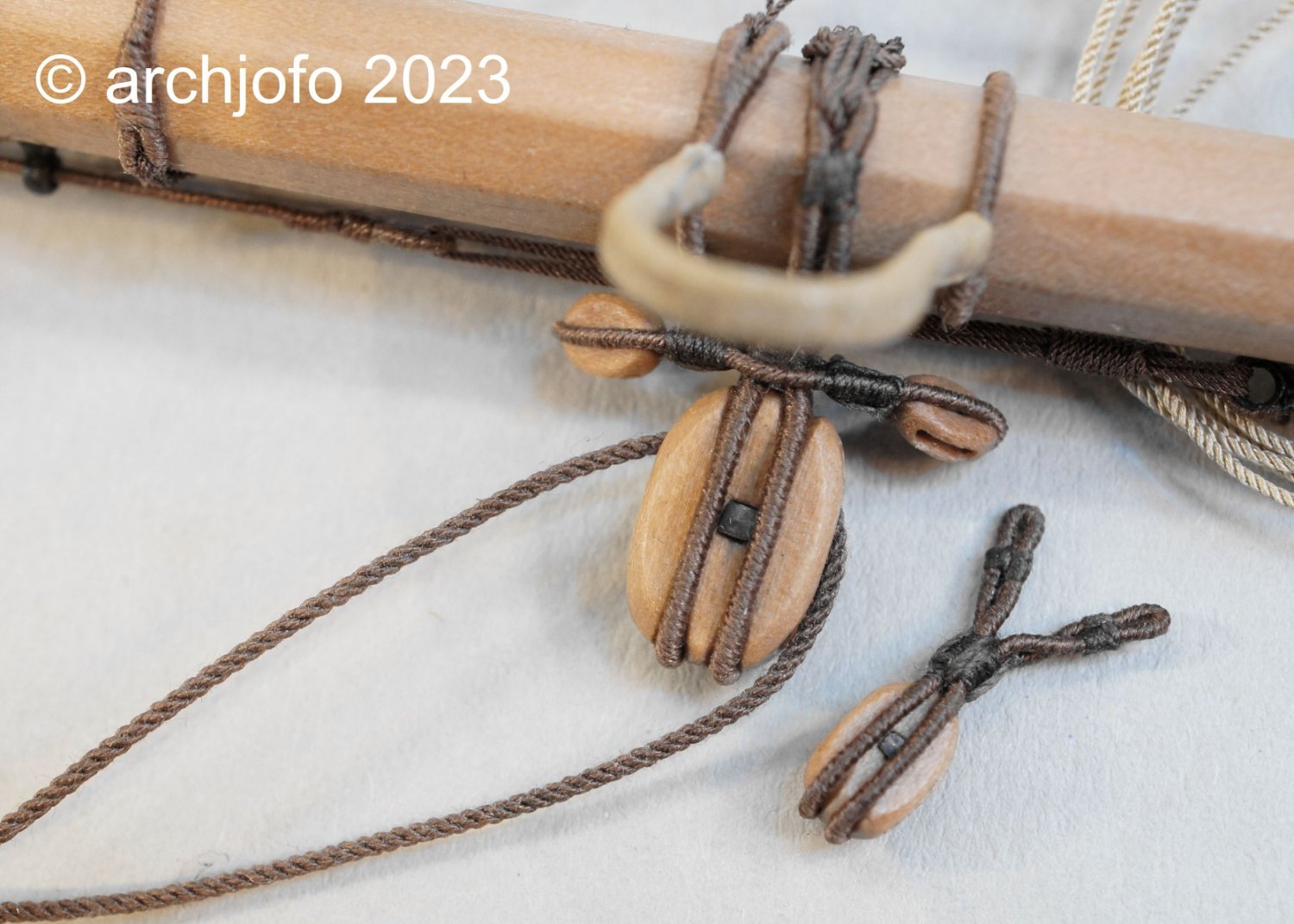
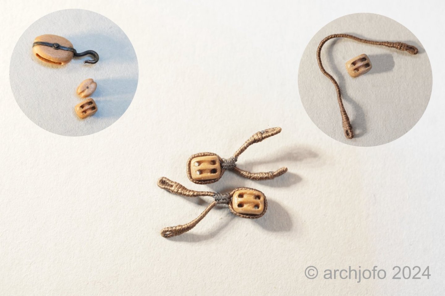
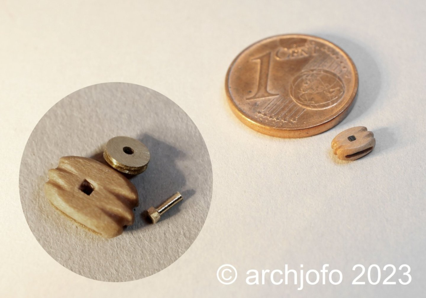
Continuation: Equipment of the main topgallant yard – Vergue de grand perroquet The next step was the production of the quarter blocks. In the first picture you can see the quarter blocks with a length of 3.0 mm that have already been provided with strops. At the top left of this picture I show these double blocks compared to a guide block that is used on the deck to redirect the topsail sheets. Here the assembly of the quarter blocks is nearing completion. Before I started making the footropes for the main topgallant yards, I tried to fundamentally clarify the execution details for the topgallant yards. In this context, I found what I was looking for in the contemporary specialist literature “Manuel de Greement” by F. A. Coste from 1829 on pages 120/121. Accordingly, the footropes of the top gallantyards of the yardarms each extended slightly beyond the center of the yard, where they were then attached. These footropes could not be tensioned with lanyards like those of the lower yards and topsail yards. Since the brams of the La Créole did not yet have a jackstays, unlike the lower yards and topsail yards, the stirrups were designed and attached in the conventional manner. This means that the ropes of the stirrups were braided and looped around the yard with two to three turns. The ends of the braids, also known as plating (in German, I don't know the English name), were fastened with flat-headed nails with leather washers. As F. A. Coste describes, the number of stirrups in the topgallant yards must be chosen depending on the yard length. For a corvette like the La Créole, one stirrup per half of the yard should be sufficient. To make the stirrups, I was able to find the following in the specialist book “The Ashley Books of Knots” by C. W. Ashley: Of course I had the ambition to implement this detail for my Corvette too. After tying in the thimble, the braid was made after unraveling the rope of the stirrup. This is how the meaning of the braid became clear to me. Since these were no longer round but flat, they could be wrapped very well and tightly around the yard and securely nailed down. Since I still had a main topgallant yard as scrap from making the yards, I was able to try out attaching the braids to it. The result can be seen in the next picture. I think that's how I'll ultimately implement it at the topgallant yards. Sequel follows …

-
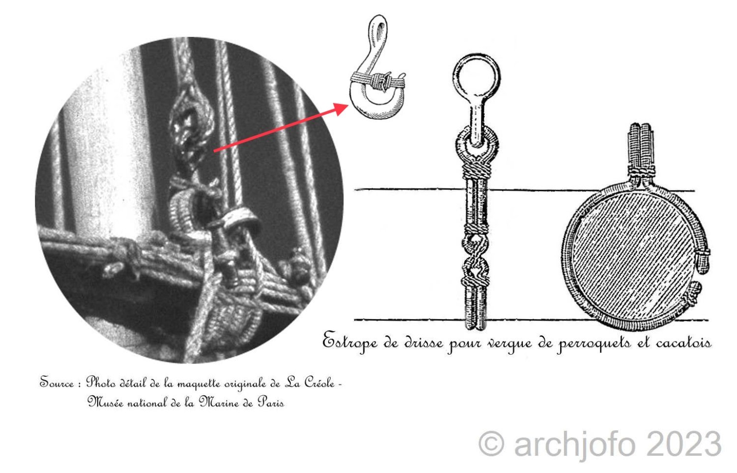
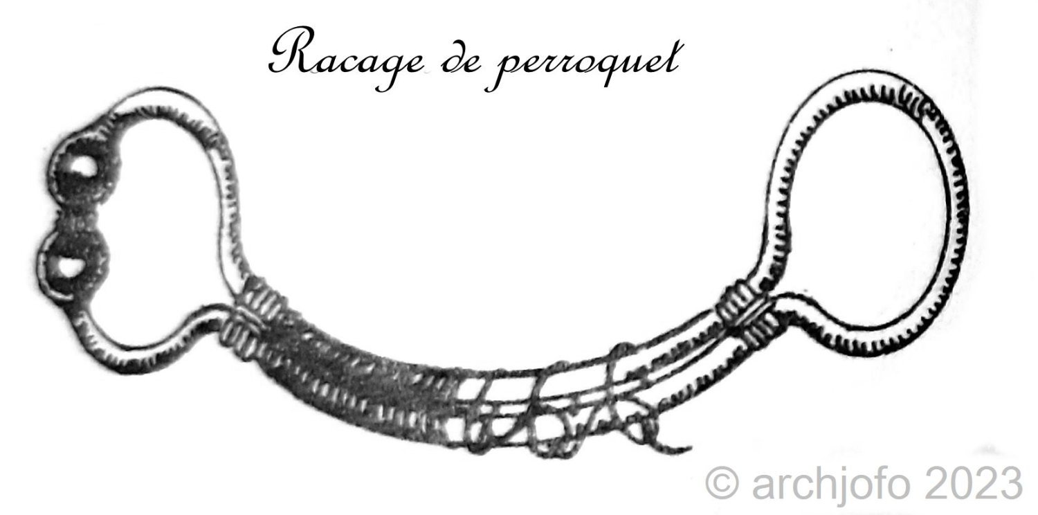
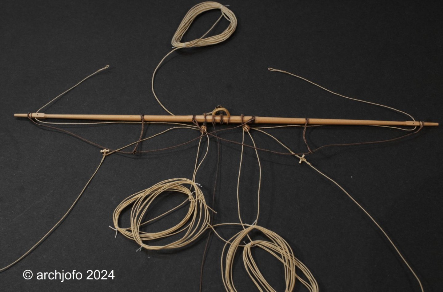
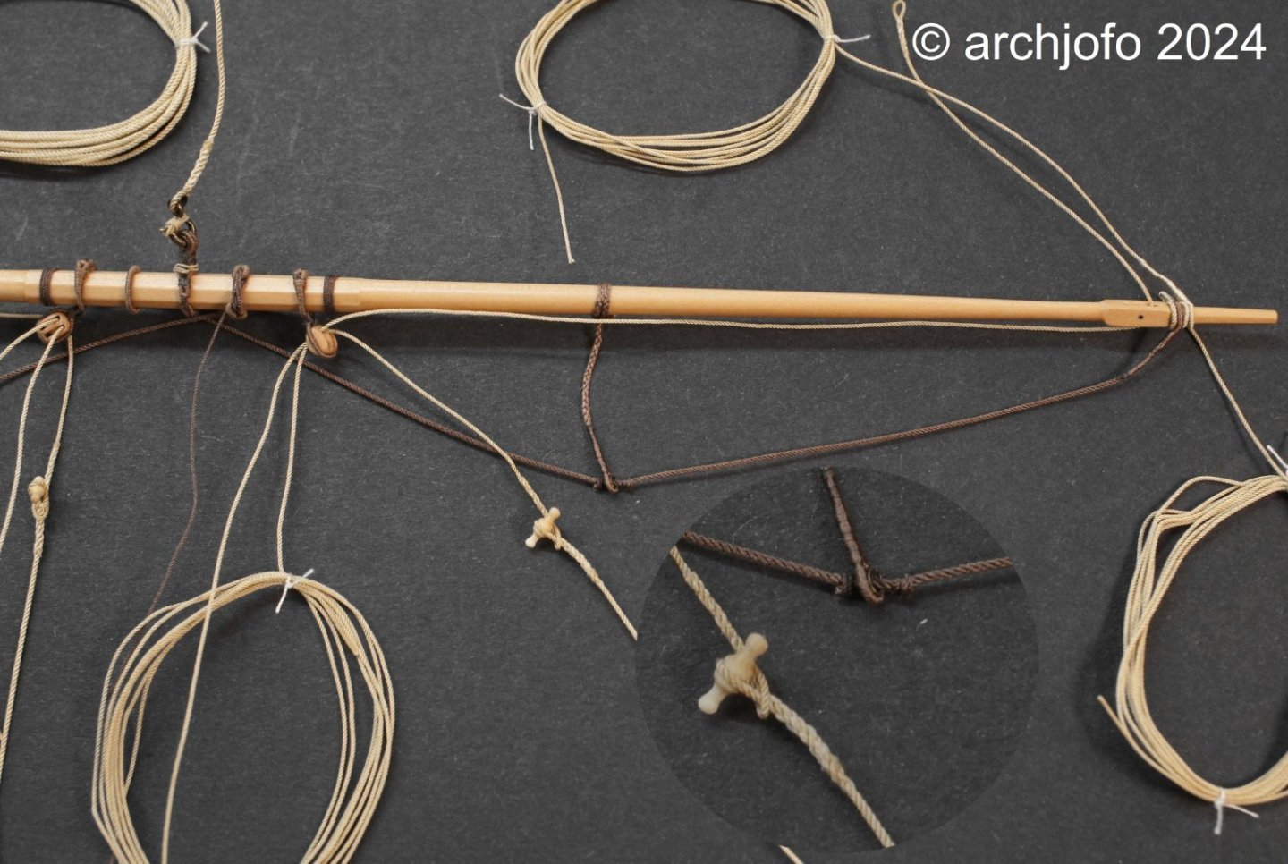
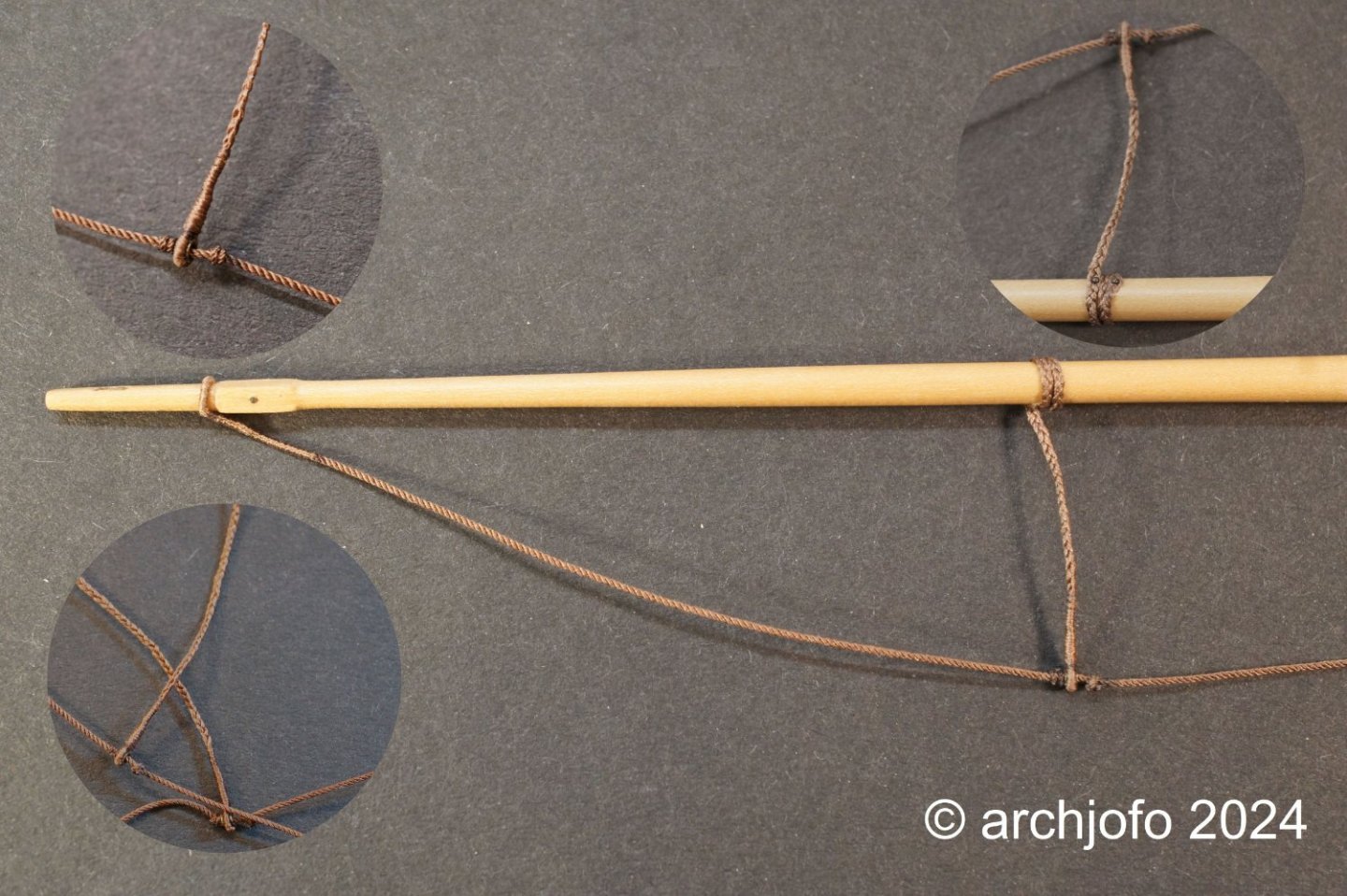
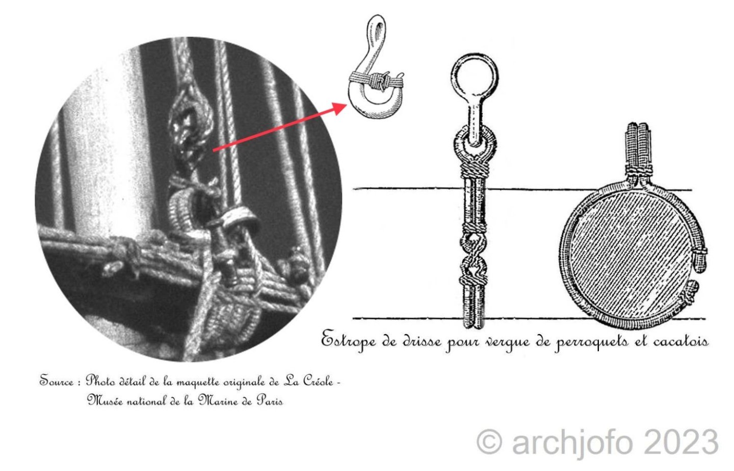
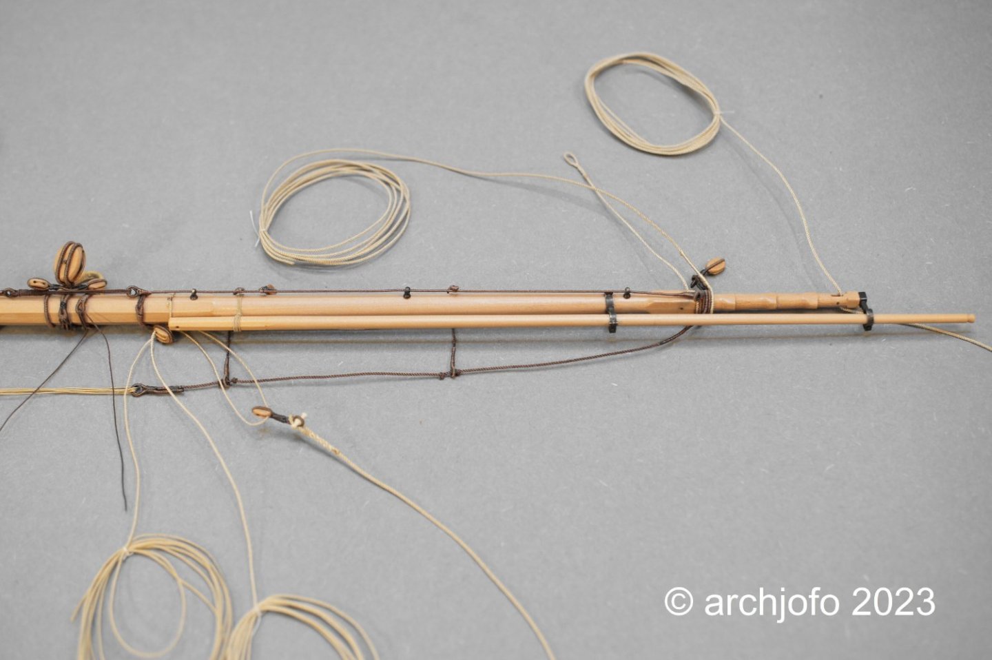
Equipment of the topgallant yards– Itague de vergue de grand perroquet In the meantime I'm working on equipping the topgallant yards. I'm slowly starting to get the feeling that the higher I get in the rigging, the less information there is about the details; be it from the monograph or from the relevant specialist literature. There is obviously less to be found on the internet. Apparently it is due to the importance or meaning of the components, as a large yard literally has more weight. Or to put it somewhat jokingly, the higher the air, the thinner the air..., of course, meant the information density... 😊 So I brought together information about the execution of the truss from a wide variety of sources, as can be seen in the following pictures. Accordingly, from my point of view, I was able to clarify the execution of the tye with the double strop for the top gallant. I think that this detail can also be used analogously for the royals. Source: Detailed photo detail of the original model Musée national de la Marine – edited / Atlas du Génie Maritime – edited The implementation for the main topgallant yard of the model then looks like this, as shown. The “mousing” as a hook lock is only attached when the yard is finally equipped. We then continued with the truss. This was made like the truss for the topsail yards with leather coating. The following drawing by K. H. Marquardt, but served. Source: Karl Heinz Marquardt, Masting and Rigging of 18th Century Ships In the last two pictures you can see the tye and the truss for the main topgallant yard, which will only be finally lashed to the topgallant mast of the model later. In the next step I will work on making the quarter blocks as double blocks with a length of 3.0 mm for the topgallant yards, which are used to guide the royal sheets and clew lines. So, see you soon….

-
I would also like to congratulate you on completing this beautiful model.
- 113 replies
-
- 3
-
-
- Cheerful
- Syren Ship Model Company
- (and 1 more)
-
Very nicely demonstrated how to mill the bevels on the knees. Thanks for showing us that.
-
@matiz @jfhealey Hello, many thanks for the nice comments, and also thanks for the LIKES. Actually, the equipment elements of the individual yards are more or less repeated again and again, except that the further up you go in the rigging, the smaller the dimensions. So I could deal with this chapter in a condensed form. But if you know me, you know that I'm merciless until the last yards ... 😁 Completion: Equipping the mizzen topsail yard - Vergue de perroquet de fouge The clew lines with the corresponding blocks, the sheet and the lifts were added to the final equipment of the mizzen topsail yard. See the following pictures: I'm still not quite sure whether the reef tackles should be simple and with a hook or with a block. I still need to do some research on this. Regardless of this, this yard will now be put to one side with the already equipped yards and work will begin on equipping the topgallant yards. To be continued ...

-
42ft Armed Longboat 1834 by Ainars - Ancre
archjofo replied to Ainars's topic in - Build logs for subjects built 1801 - 1850
Hello, absolutely perfect construction of the frame structure. This will be a top model. I also built a 1:48 scale longboat for my French corvette. If you are interested you can see it here LINK. But it is not comparable to your precision work.- 12 replies
-
- 1
-
-
- Armed Longboat
- Ancre
- (and 1 more)
-
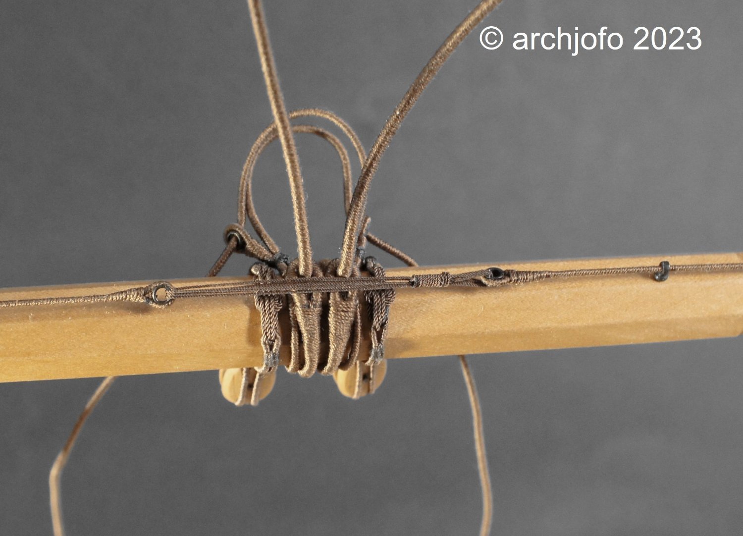
@giampieroricci @Nunnehi (Don) Thank you very much for your interest in my work and the kind words. I would also like to thank you all for the many LIKES. A happy new year 2024 to all. Continuation: Equipping the mizzen topsail yard - Vergue de perroquet de fouge The last of La Créole's topsail yards, the mizzen topsail yard, has now also been fitted with a jackstay and lashed in the middle. The next step was to make and attach the footropes with a rope ø 22 mm (model scale ø 0.46 mm). Due to the relatively short spans, one stirrup for each half of the mizzen topsail yard seemed sufficient. The next step was to make the strops for the yard tackles, which will later be attached to the yardarms. The next picture shows detailed sections of the rigging elements already mentioned. A comparison with a stirrup for the main yard is also shown. The following picture shows the finished blocks (each 3.5 mm long) for the braces and the leech lines. As with the other yards, the blocks were attached directly to the yard strops using ø 1.4 mm thimbles ("dog and bitch" connection). I continued with the strops for the lower blocks of the clew lines (l = 3.5 mm) and making the toggles to connect them to the sheets. Last but not least, a picture of the current state of the mizzen topsail yard. Finally, the clew lines, the reef tackles and the sheets are still missing for the final outfitting of the mizzen topsail yard. See you soon ...


-
How metal hooks are stropped onto block
archjofo replied to glennb17's topic in Metal Work, Soldering and Metal Fittings
@glennb17 Hello Glenn, I just saw your post today. Even though I may be late, here's my hint. I have already dealt with the question. I solved it like this based on historical drawings. LINK (please scroll down) Maybe that's a little help. -
A few quiet minutes between the holidays can be usefully filled...😀 Equipment of the mizzen topsail yard – Vergue de perroquet de fouge In the meantime I have started equipping the mizzen topsail yard of the La Créole. The first step was to make the necessary blocks and thimbles, as shown in the first picture. The tye block has a length of 5 mm and is therefore the largest block at the mizzen topsail yard. The next picture shows the size ratio of the tye block of the mizzen topsail yard to the tye block of the mizzen topsail yard. The difference is clear, as the mizzen topsail yard itself is significantly smaller and therefore lighter. In the last picture the first rigging elements are already attached, such as the tye block with the stropped blocks for the bunt lines, the truss and the quarter blocks. I cannot tell from the images available to me to what extent the mizzen topsail yard was equipped with a jackstay. I can't find any information about this in the monograph either. Nevertheless, I tend to equip the mizzen topsail yard with a jackstay. Up soon … Wish you all a happy new year!


-
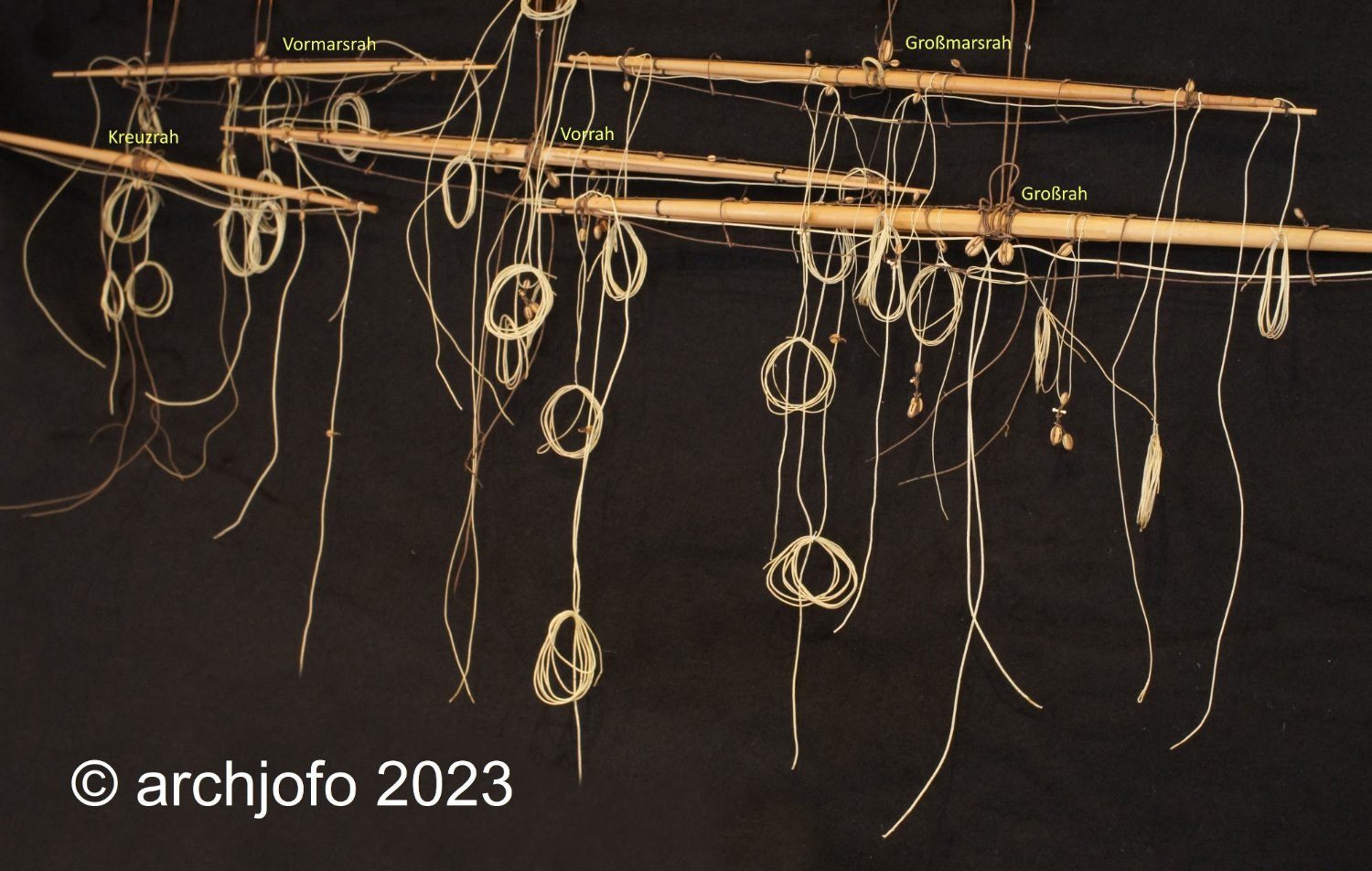
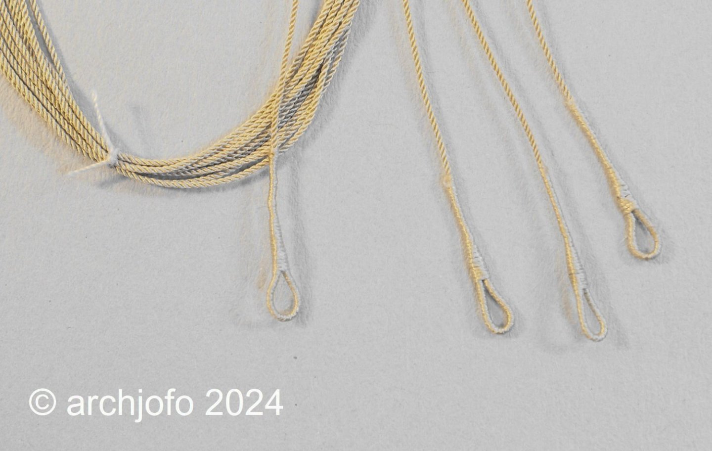
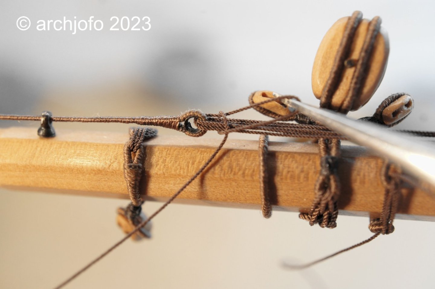
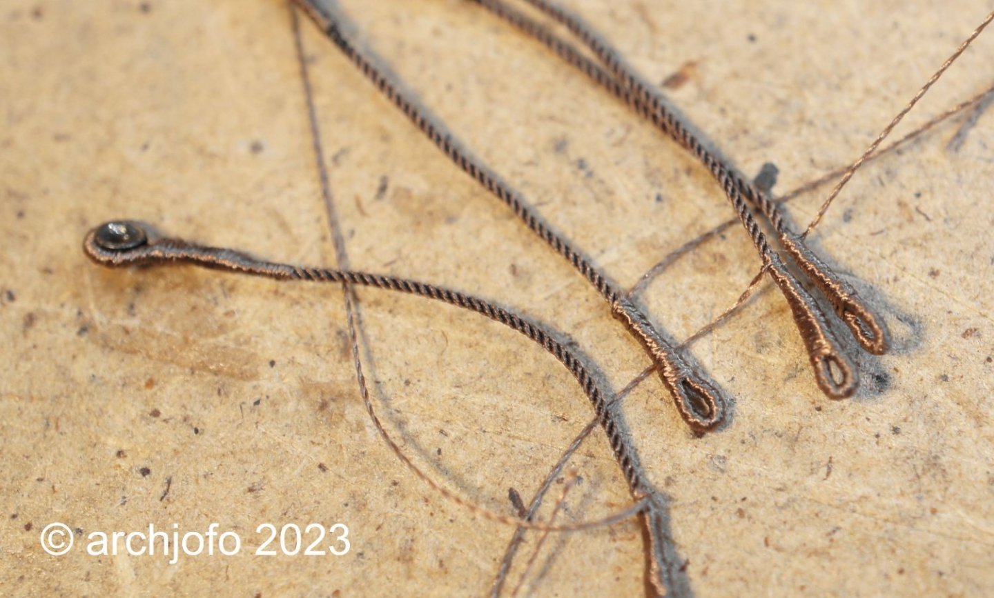
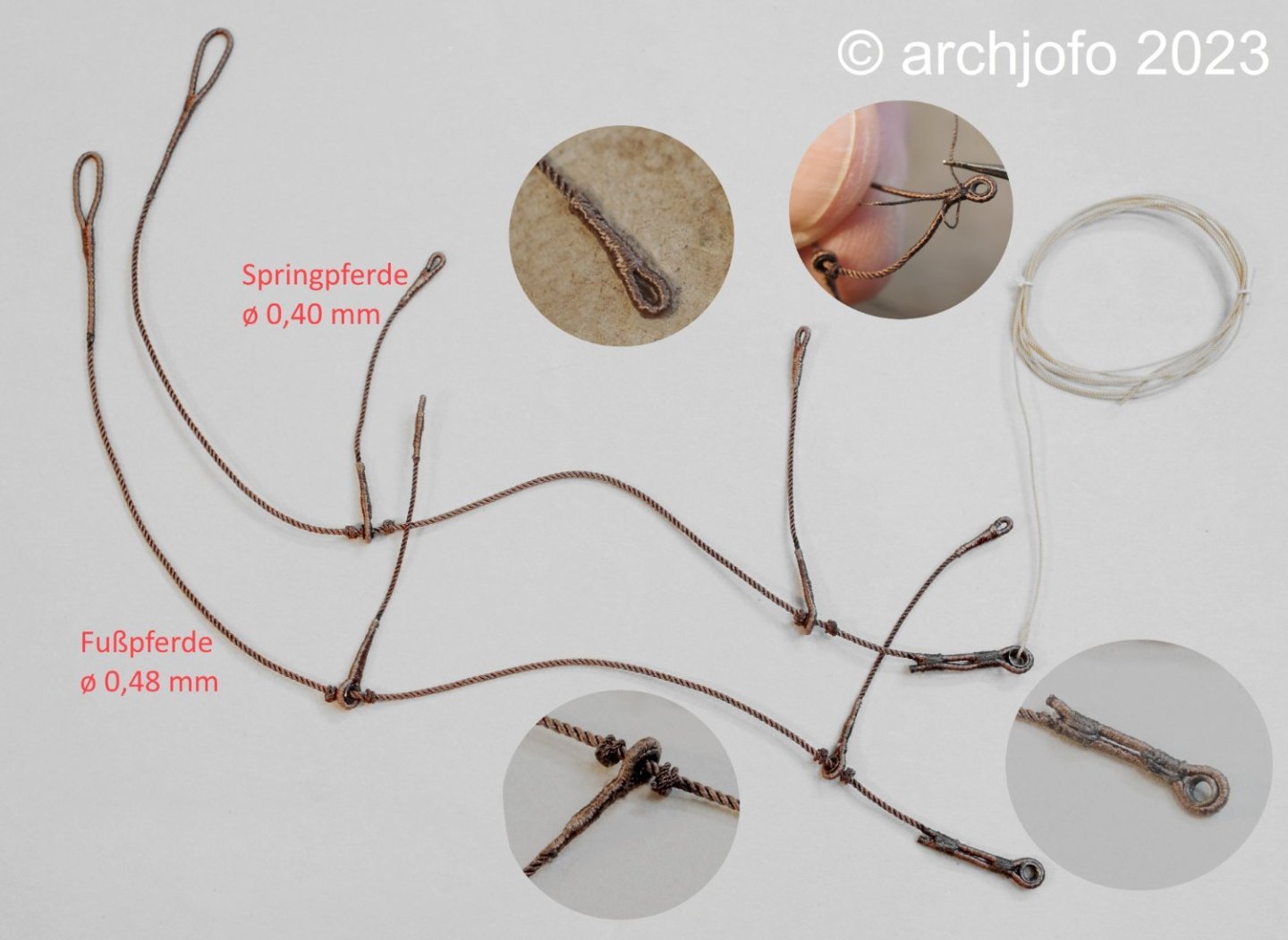
Hello, wish everyone here in the forum a . Completion: Equipping the fore topsail yard - footropes and stirrups / Marchepieds et étriers etc. By pulling in and tensioning the lanyard, the two halves of the jackstay were tensioned. The loose end of the ropge was carefully wrapped around the lanyard and tightened, as shown in various historical drawings. The footropes and stirrups for this yard were then made in the same way as for the main topsail yard, but with slightly reduced rope diameters. The following picture shows the already prepared stirrups. Thimbles are spliced into one end of them, through which the rope of the footrope will later be pulled. The other ends were formed with served eye splices, which are then lashed to the jackstay. The next picture shows the finished footropes with details. I continued with the lower blocks for clewlines l = 3.5 mm and the toggles to connect them to the topgallant sheets. As already mentioned, I made these from dogwood, a very hard and fine-grained wood, which is ideal for these small parts. The following picture shows the stropped blocks for the clewlines, one is connected to a sheet. Next to it is a block for the main braces for comparison. Here you can see the stropped blocks for the braces before they are placed on the yardarms. Here you can see how the studding sail booms are attached. The next pictures show the fore topsail yard equipped with the necessary elements for rigging. Last but not least, a picture of the yards fitted out so far. Quite a jumble... 😊 We continue with the cross yard. To be continued ...


-
@Dowmer Hi, I haven't yet done the lashing of the jackstays in the middle of the fore topsail yard. But I'll show you the detail at the main yard. As you can see, the end of the rope is wrapped around the lashing ring for a few turns and then secured. There are also various methods for this, such as this one: I hope that I have helped with this.

-
Brig Le FAVORI 1806 by KORTES - 1:55
archjofo replied to KORTES's topic in - Build logs for subjects built 1801 - 1850
Very nice detailed work !