


ianmajor
-
Posts
784 -
Joined
-
Last visited
Content Type
Profiles
Forums
Gallery
Events
Posts posted by ianmajor
-
-
Moving on from cross-eyed cannon I am trying to improve certain parts of the 30+ year old hull before fitting any of the less ocularly challenged barrels.
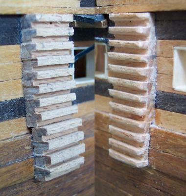
First up was the steps either side of the waist and in the heads area. Corel supply "L" shaped beech strip to make these. I used them as supplied but they were rather heavy in appearance. I would rather have replaced them with something neater. However, since they have been in place a long time my concern was that any exposed planking would look considerably lighter than the adjacent parts that have had long term exposure to the elements.
So I used a chisel and files to carve them back and to round all the edges except the tops of the treads. The photo is a before (left) and after (right) montage.
I gave the steps behind the heads the same treatment. The lowest of these steps I cut a recess to take the bowsprit.
In one of my discussions with Mike he pointed out the the Corel plan has two sets of gammoning. Lees says that most ships only had one set, the exception being the largest. I had already made provision for the two sets so the rear of the two holes I covered with extra grating. The second hole in the keel part will stay open - hopefully no-one will notice it.
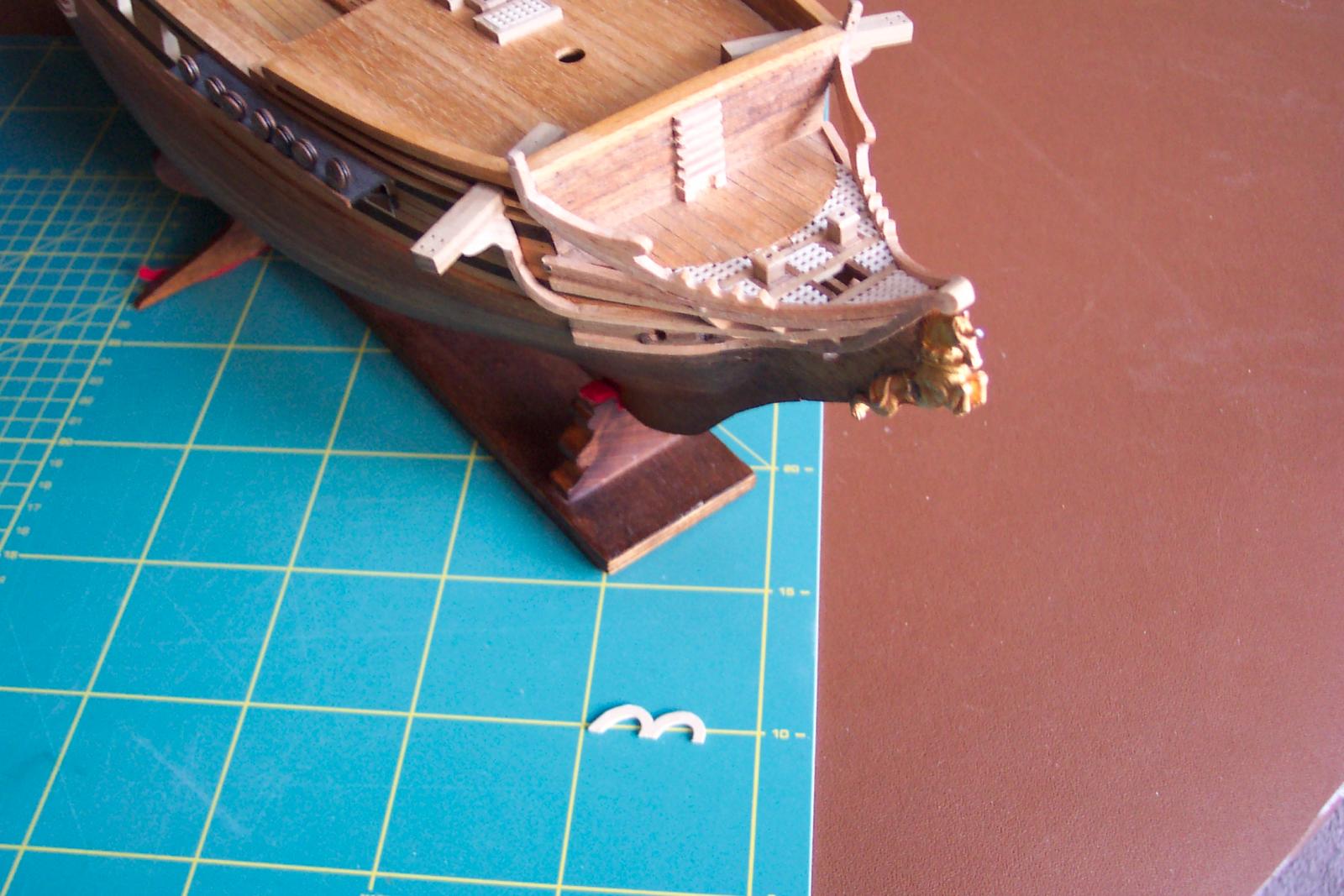
The next photo shews the trimmed steps and the extra grating fitted. It also has a couple of arches on the cutting mat waiting to go on to the gallery.........
I would love to replace the transom and galleries with something nearer the mark but this would involve major surgery. So I am going to content myself with cosmetic improvements.
The galleries being too narrow and positioned incorrectly result in the top and bottom castings being too big giving large overhangs. I trimmed the castings back which loses some of the detail. The sides of the galleries look drab anyway.
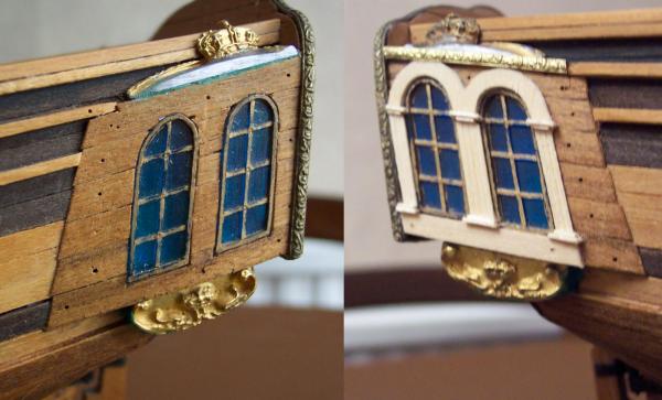
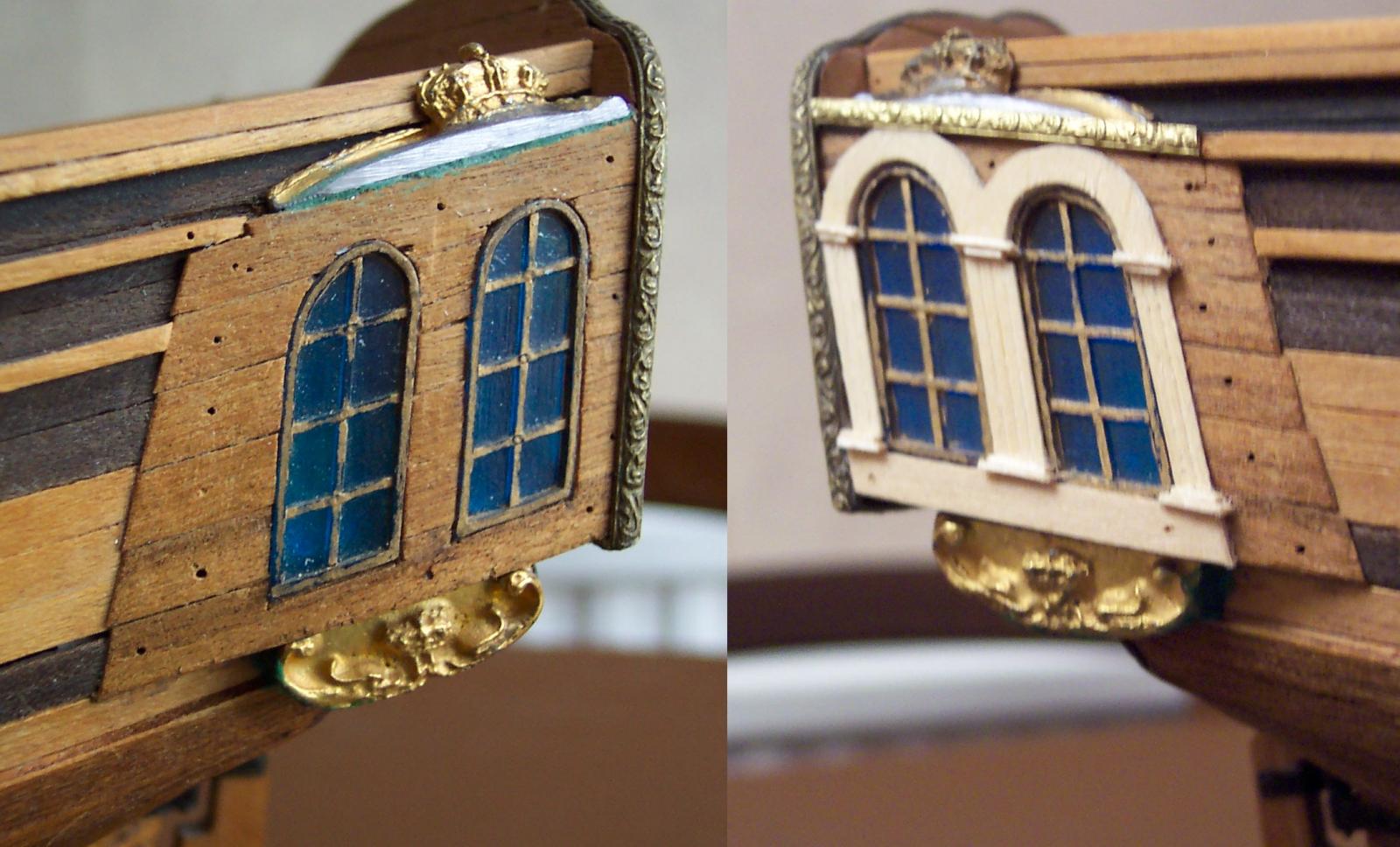
So I looked around the various galleries produced by the likes of Chuck, Dan Vadas, Remco, BE and others to get some ideas. I decided on arches over the lights/windows and columns between them. The missing detail on the top casting was replaced by some Coral decorative strip which is made of hard brass. I have a small amount of filling to do and the castings need to be painted.
Getting the shapes of the arches over the windows correct is interesting. They are a skewed elipses. To copy these I use a soft pencil on thin paper to do a sort of brass rubbing. From this I can cut out a template from the paper to use on the wood.
The next photo is another before (left) and after (right) montage. Of note is the colour of the new sill under the lights/windows and the colour of the wood between the ebony. These are both lime strip supplied with the kit. The strip between the ebony had had 4 decades of exposure the other sat in the Corel kit box for that period of time.
I am intending to do something around the rear lights/windows.
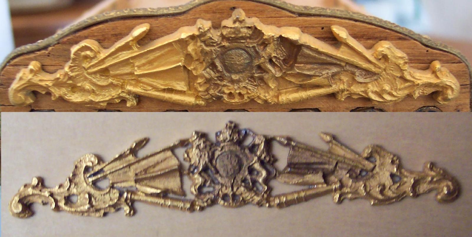
I toyed with the idea of carving new figures for the transom but I don't have any suitable wood, or skills for this. I opted on trying to improve the Corel supplied casting. This is a fairly large, guilded white metal job. It looks crude because it is so thick - 2mm or so. The detail is within the outer 1mm of this depth. To give it rigidity the individual figures have thick webbing between them.
So I prized the casting off the transom and clamped it to the milling table face down with thick card under it to protect the detail. Then I milled off about 1mm of its depth. The indication of when I had gone far enough was the webbing starting to drop out. The rest of the webbing was then easily removed. Again another before (upper) and after (lower) montage.

Now to attempt the production of matching arches for the rear lights.

- IgorSky, dafi, Landlubber Mike and 4 others
-
 7
7
-
Mike,
I think you have a good approach on the rabbet. I just checked the rear of the keel. No sign of any sanding down around the bearding line - I can see the edge of the 3 plys all around - another reason for some form of edging around the keel. I don't remember the instructions calling for sanding here - at the time I thought a bearding line was something to do with my face, so I would not have considered doing anything with it. (The ship that is not my face.
 ).
).The bulkheads I fitted so that they were in line with the top of the keel as per diagram 2. One of them (I seem to remember it was about bulkhead 3) then extended below the bottom of the keel so I took a file to bring it in to line using bits of string across the other bulkheads.
Great time with the grandkids. I have made up a pirate ship with my grand-daughter. Perhaps I should put a photo of it in my log.
-
Mike,
Excellent work.
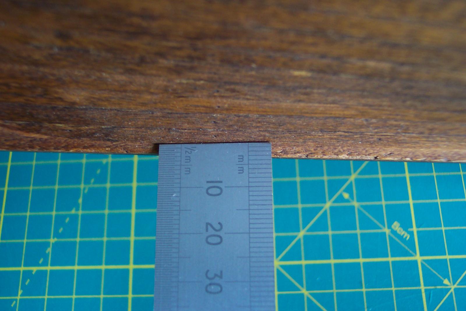
An area I had problems with around the keel was along what should be the rabbet (again not sure if this was changed in the later kits). The double planking approaches 3mm thick. The bulkheads extend down quite low so that when the planking was complete there was only about 2mm or so of keel left exposed. Tried to photograph this - hope you can see what I mean. The rule slightly overlaps the planking on the right hand side - the left side is right on the edge of the planking.
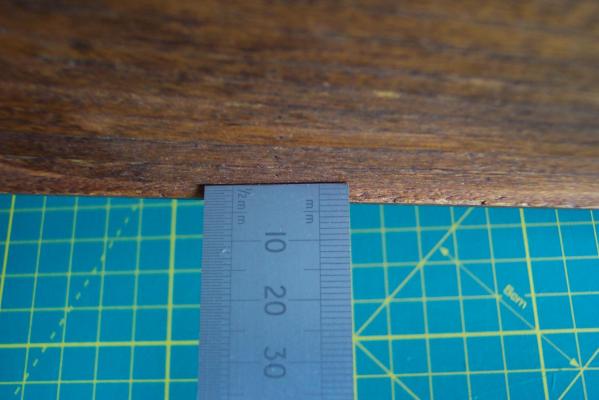
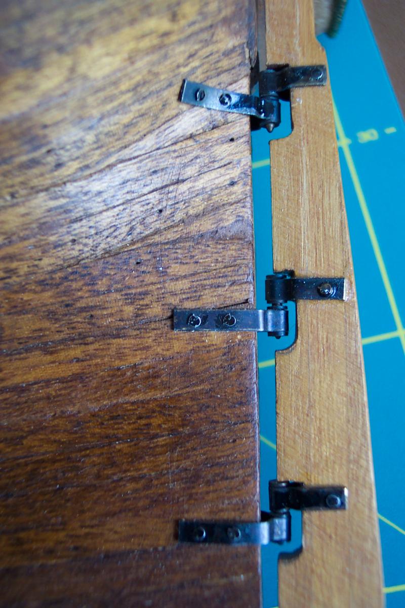
Another plus point about adding a stern post is that the gudgeons will be much easier to fix. On mine the top one fitted straight on to the flared part of the stern - a real pain (plus I guess there should be more than three of them.
) .
. -
....on constructing the counters...
If I remember correctly the counters (pre-planking) are produced with two pieces of wood moldings ie the curve shape is already in place. These are attached either side of the keel piece to bulkhead 16 just below the position of bulkhead 17.
It is possible to fit (up to) bulkhead 16 and the counter parts as per Corel but keep part 17 loose. Then you would be in a position to try out some dry run options such as making a set of "L" shaped supports to fix to these to support the transom. If they prove too difficult - no worry - off they come on goes part 17 and the construction can still be as per Corel.
-
Mike,
On the stern - I don't think there is a need to move the counter forward. If you add a stern post this would in effect produce the same result without affecting the geometry of the counter. As you pointed out, the keel part is short by about 5mm so you will simply be correcting that. It certainly would making the rabbets for the rear end of the hull planks very much easier to make.
-
Piet,
Very nice work and it continues to be a fascinating read. Following all your detail I feel as though I could almost find my way around a real submarine.
-
Mike,
I decided to create a scale rule for the Chapman diagram so that I could get some real scale lengths to check the model against. Chapman has three scales being S, E and F. Since Chapman was Swedish I decided that they were Swedish, English and French. To confirm this I looked up the old definitions for feet in these three countries. They came out as:-
Stockholm (Swedish foot) pre 1863 = 29.69cmEnglish foot from 13th century = 30.48cmFrench pied du roi pre-revolution (1795) = 32.48cm (after 1795 there was no roi to have his pied measured).I calculated the ratio between these values and they match the ratios between the three scales.So I will use the E scale for the scale rule. Of course Corel may have used the Stockholm foot.
-
Hum,
Yes. Corel does have the channels low down. The fore channels on Chapman only extend back beyond the rear edge of the fore deck bulwarks by a small amount. Corel has the extending by about one third their length beyond the bulwarks. The bulwarks on the model actually stop short of the rear edge of the fore deck so it may be just a case of extending the bulwarks a little.
This may improve the possibility of fitting a fish davit which is squeezed out in the Corel arrangement.
I have my channels higher than the Corel plan but still under the rail. I wont try to claim this was by design.

I have my measuring stick out for a look!
Great fun this.

-
....and yes Mike, you are also right. Whilst comparing with Chuck's model it became obvious that the Corel model has NO stern post. That would be easily added and look much better.
-
Mike,
The tiller arrangement has been bugging me and I have given it more thought. This would have some effect on the work around the top end of the keel piece.
I have convinced myself that the tiller would have been above the quarter deck. Below is an extract from the Chapman diagram:-
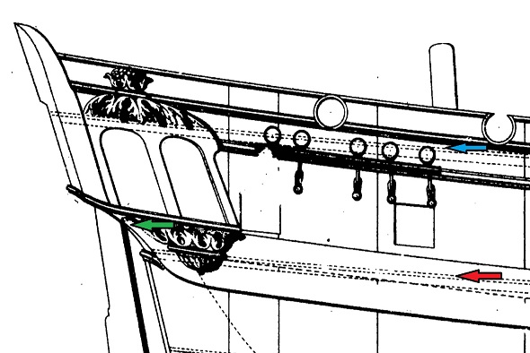
Chapman marks the deck levels by parallel pairs of dotted lines. I have added some arrows. The blue marks the quarter deck the red the upper deck. I have also marked the top of the stern post with a green arrow.
Now the tiller would sweep back and forth above the top of the stern post. If it was mounted immediately above the stern post that would put it and its sector plate in the great cabin - bit of a no no. Hence my belief that it was actually above the quarter deck. Is it time to dig out the plans of your Badger and scale them up a bit?
As you noted previously the Lyme class had very low head room on the lower deck and later ships had this headroom increased. The later frigates were also increased in size. I have compared the counter on the Unicorn and the Lyme with the slightly later frigates. The Lyme class had a single curve at the counter, the later ones had two curves, the upper one corresponding to the seat level of the great cabin. I have borrowed an image from Chuck's Winchelsea to illustrate this (I hope he doesn't mind).
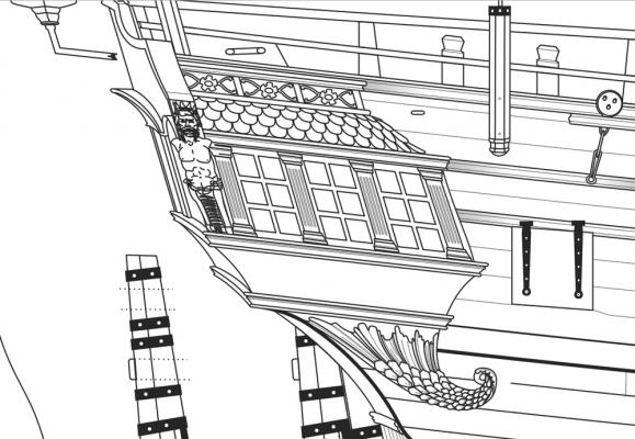
Notice its twin curves compared with the single curve on the Unicorn. On Winchelsea the tiller is able to enter below the upper deck level.
The tiller being on the quarter deck raises a few more questions.
With it and its operating ropes occupying much of the area behind the mizzen mast I can't see how cannon could have been used at the rearmost quarter deck ports.
The rudder would have passed right up through the great cabin at the rear obscuring the central window. Was there an actual window there? Was it a trompe l'oeil?
What do you think? Or am I talking b******s?
BTW Have you seen Chucks latest on his Winchelsea (link) ? He is in the process of producing the stern galleries. Very useful.
-
John,
It is great that Mike's and my discussions have benefited others. We have had plenty of input as well from ZyXuz , Ollyweb, petervisser and others. That is the great thing about this forum.
My suggestion was to make a beefed up transom which would replace bulkhead 17 rather than be attached to bulkhead 16 so there would be no narrowing of the hull. Replacing bulkhead 17 with a part that is the width of the galleries brings the galleries forward by the thickness of the bulkhead.
Ideally the transom part need to be replaced. In entry 3 of this log Mike put a link to an image of the Chapman plan (link to plan) . From that you can see the underside should curve downwards at each end. By replacing the transom part you can also get better window shape and spacing.
My Unicorn is too far advanced to make these substantial changes but I had contemplated planking over the lower parts of the windows in the way you suggested. Your prompting may make me reconsider this.
How about starting your own build log? We can then have plenty of happy times comparing and discussing the various builds.
Mike, don't feel bad about me spending time playing with the children's coloured pencils - if I wasn't doing that my wife would probably pack me off to the local day centre to make cane baskets with the other ancients.
(sorry for pinching your log space ) -
I use a small brush and touch up with a tiny amount of neat gun blue then wash off after about a minute. I don't use the brush for anything else since gun blue is rather nasty stuff.
-
Mike,
Have had a happy couple of hours doing real cut and paste with bits of paper, glue and my grandchildren's coloured pencils. Very therapeutic.
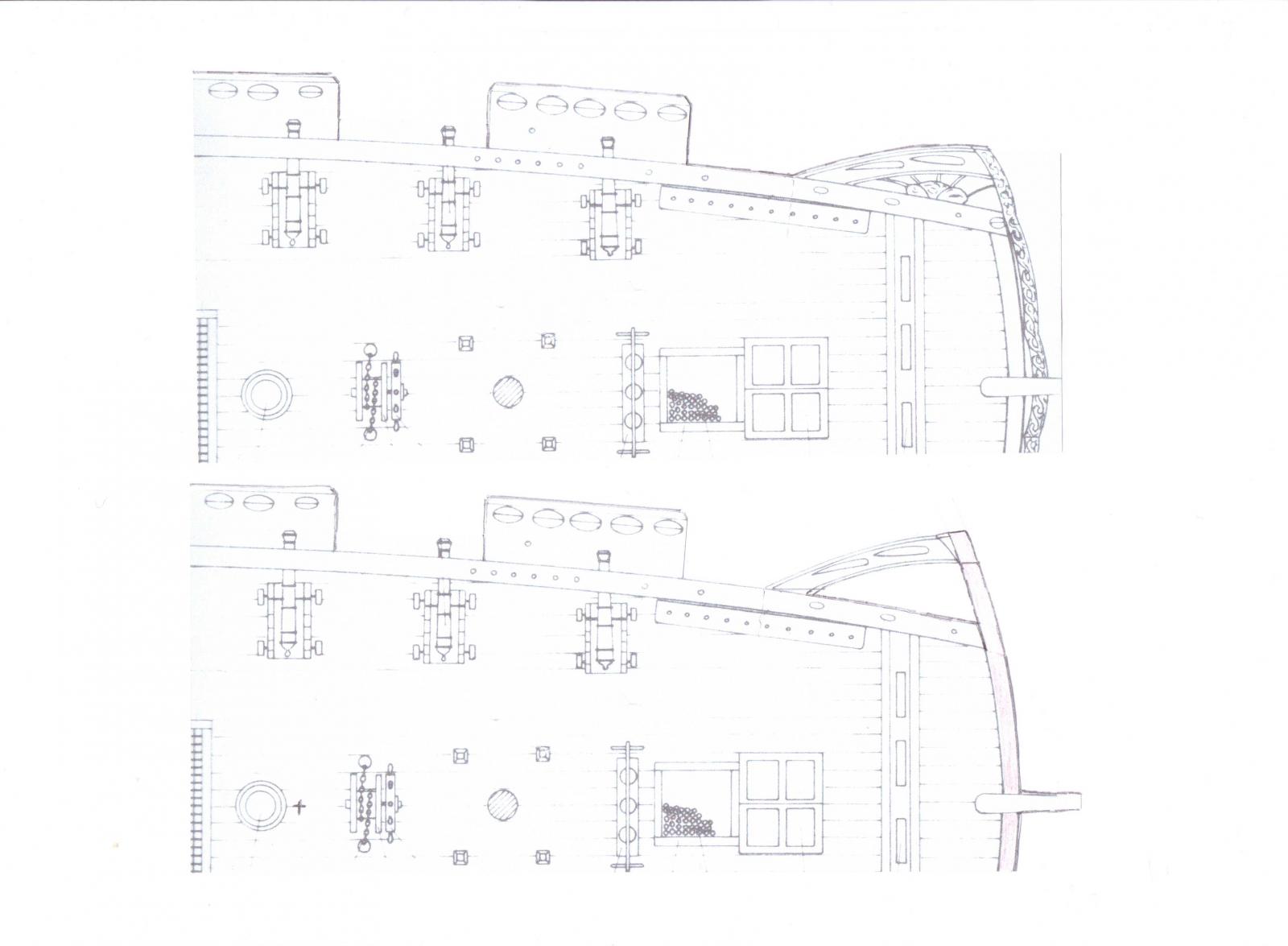
The result - two images with what I believe the galleries would look like with bulkhead 17 removed. Each have the original Corel plan at the top with a modified version below. (Click on the pictures for a clearer view).
They include the rake of the transom increased to 16 degrees. This seems to make quite a bit of difference. It is pretty close to the Chapman diagram.
Joe's Granado stern construction looks the ticket. I guess that was how your Badger was also constructed.
Another thought at the other end of the ship before I forget - the hawse holes as per Corel I think are too low. Chapman shews the ridding bitts on the upper deck (which is where I have added a set). I would therefore expect the hawse holes open in to the same deck. The Corel position would make them open in to the lower deck. I drilled mine some time ago and they now look quite silly to me.
-
Mike (I am back in waffling mode - oh dear!)
Measured up my plans and model keel. Mine show the same discrepancy - it hasn't been sorted since the early iterations of this kit
 . The length of the straight part of the keel lower edge is 468mm on diagram 1 and the model but on diagram 2 it is 463mm.
However the part of the model's keel that supports the flag lockers is the same size as that in diagram 2 but smaller than diagram 1. So you have the keel is one shape in diagram 1, a slightly different shape in diagram 2 and actuality is somewhere between the two.
A thought about how to bring the galleries further forward without actually shortening the keel. What about discarding bulkhead 17 and fixing a transom piece directly in its place. The hull planking would fix to this as would the gallery parts. This would bring the gallery forward 5mm, which along with a steeper transom angle (4mm gain) and wider galleries (2.5mm gain) would bring the lower edge of the galleries forward by 11.5mm which puts them more or less in line with Chapman.
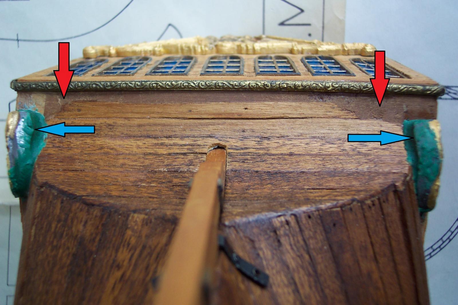
The lower edge of bulkhead 17 is wrong anyway (if you think of the geometry of a part curved in the vertical plane sitting on a part curved in the horizontal plane). It curves up when it should curve down. The lower edge of the transom part should also curve down where Corel has it straight (I think for simplicity). When I fitted my transom piece planking to the bottom of bulkhead 17 left me with a couple of hollows that I had to fill in due to this error.
In the photo the red arrows point to this filling. The blue arrows point to filler used to support the "floating" parts of the decorations.
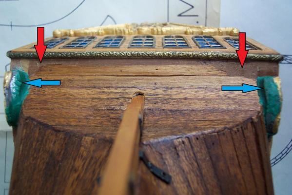
My referring to the "transom part" is probably wrong but you know the bit I mean.
I am doodling some diagrams to shew what I mean. I will upload them a bit later.
-
-
-
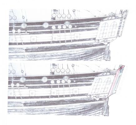
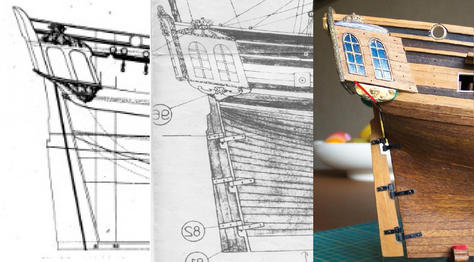
Mike,I previously did some work comparing the various diagrams to see what I could do to improve the stern of my Unicorn. I abandoned the effort due to the mass destruction that would have been required at this point in timeI just tidied these up and thought you might be interested in what I produced.First up is a composite image of the side view of the stern. The left of the image is the Chapman view, middle is Coral and right how it turned out on my ship.
 As you noted the rear edge of the gallery sides line up with the front edge of the rudder in the Chapman view. Corel has the rudder front edge lying between the gallery windows.The next thing that struck me was that the transom in the Chapman diagram was at a different angle to Corel. Measuring up using the bottom of the keel as a horizontal, the Chapman transom is 16 degrees off vertical, Corel has it only 11 degrees. This makes the Corel transom look a bit sit up and beg.With the gallories being so far back this gives the problem of overhanging lower decoration - the red line in the image on the right indicates the amount of overhang (and that with a much reduced casting!)Next up is the same comparison made on the rear of the transom.
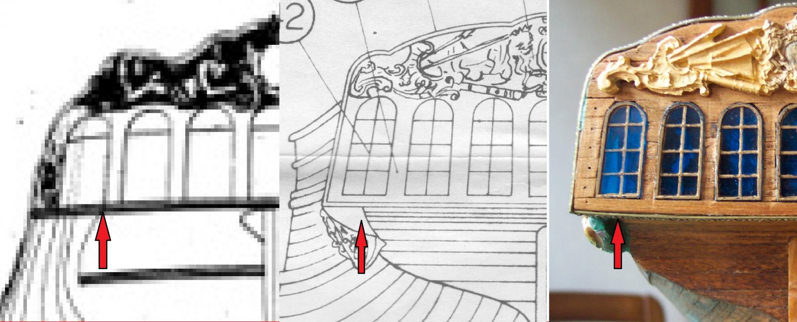
 I always felt the Corel galleries were too narrow and I think this demonstrates it.On the model it is possible to make out the rear edge of the bulkhead which bisects the gallery rear window (indicated by the red arrow). The Corel diagram is the same. The (rather pixelated) Chapman diagram shews a wider transom which obscures the hull to its side (the Corel diagram has a lot of hull showing at the side).On the model the gallery internally is just over a scale 1 foot wide. Now considering the captain's commode was in this space backing on to the rear window leads me to the view that the captain would feel a bit squeezed and rather upset when sat there.Next is a bit I got wrong that is worth noting.
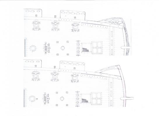
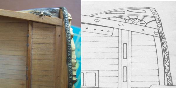 The transom should be curved. The instructions do say to shape the rear bulkhead to give this curve. As you can see in the photo my transom is pretty close to straight so that also pushed the galleries towards the rear.There was a difference between the Corel deck plan (in the photo) and the Corel plan of the keel part. The raised part at the rear of the keel which determines the length of the lockers was much shorter in the keel plan than in the deck plan as can probably be seen in the photo. The early versions of the kit had a lot of errors of this type.So I decided that:-1) The Coral transom rake is wrong (or at least doesn't agree with Chapman). Correcting the rake pushes the lower edge of the gallery sides forward. This does skew the shape of the sides.2) Each gallery is too narrow by about 6mm (ie the transom should be 12mm wider). Since the transom is curved (I worked out a radius at the top of the transom of 165mm) if the transom width is increased this also will push the gallery sides further forward.I modified an extract of the Corel plan to illustrate this. (Click on the picture to get a better view of the detail).
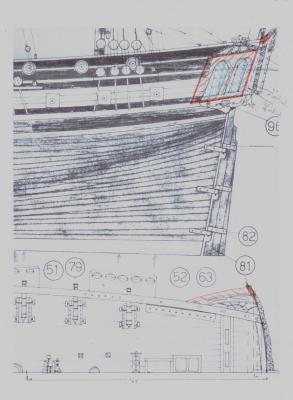 I have marked the new position of the gallery sides with red lines and hatching and the windows with blue.Changing the rake of the transom pushes the lower edge forward by 4mm. Extending the transom width pushes the sides a further 2.5mm forward. Actually with the extended transom this would probably result in the sides being lifted a couple of millimeters. All this would stop the lower decoration overhanging past the counter pane(?).However the sides are still 10mm further back than Chapman - which is not far off the length of those useless lockers.
-
Mike,
I have taken on board your wise counsel and am tackling the remaining jobs on the basic hull. In particular I am attempting to improve the appearance of the steps. For this I made a chisel with a 1mm wide blade to trim between the treads.
I also noticed the Chapman plan had 13 ports per side on the upper deck. My assumption was that the foremost was the bridle port leaving 12 gun ports.
One thing about only using 28 of the 32 guns supplied by Corel means that I won't be using these four interesting specimen....
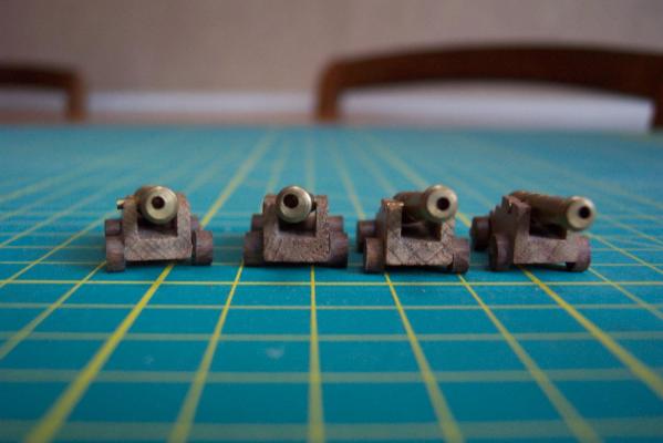
I am trying to decide whether they were some secret type of cannon that could fire around corners, thus removing the need for bow and stern chasers - or was it that 40 years ago, when my kit was produced, Corel didn't have access to a decent lathe. Hum.........
 Note - the barrels were not supplied blackened back then.
I will be fitting swivel guns in the next month or so - which perhaps will give a feel for how crowded it will get.
- Ferit, dafi, olliechristo and 4 others
-
7
-
Thanks Mike,
Good point. I have a few things to do on the basic hull. I best get those done now.
Re the cannon - I am afraid I am using the Corel supplied cannon throughout. The problem is the rings on the quarter deck are now set too high for smaller cannon and changing them would be a problem.
-
Hamilton, BE, ZyXuz and Ferit - thanks for the kind words and encouragement. It helps to keep me on track.Thanks for the likes as well.BE - I notice from your Pegasus log that you have been to deepest, darkest Herefordshire. If you cross the Malvern Hills from there you end up in the land where I was bred, born and brung up. My kids hate the place because "nothing happens there"!
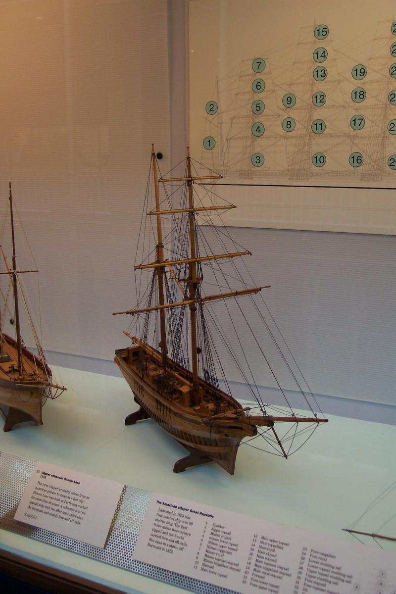
Well I have had a very nice long weekend in Edinburgh with my wife. I thoroughly recommend a visit - a lovely city with friendly residents.The National Museum of Scotland is in the centre which has amongst its exhibits a collection of boat and ship models. Most are not contemporary with the period that they represent but they are interesting none the less. I have taken some photos although the quality of them is not good. The models are in cases made with relatively small panes of glass and some have mirrors behind. When I have sorted them I will put them in to a separate log. In the meantime here is one of them that took my fancy.It is a 20th century model of the clipper schooner Bonnie Lass of 1868.
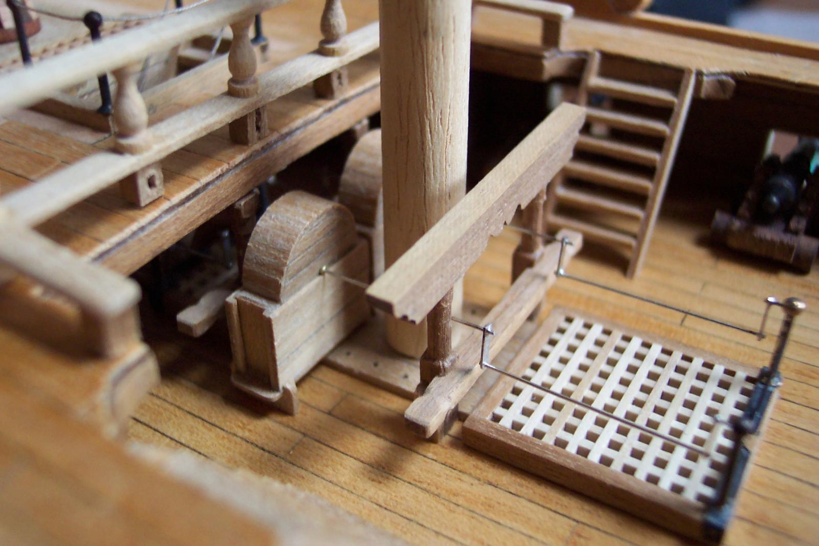
 If you want to see descriptions and official photos of the collection go to http://nms.scran.ac.uk/ and put in to the search field (top right on the page) key words "model ship" to get the ship collection or "model boat" to get the boat collection.So - on with the old wreck.I finished planking the hoods with some closure planks. Then it was time for some crank handles. I cut some short lengths of 1mm diameter brass tube, which has a 0.4mm internal bore (this stuff is great for making working hinges). Fitted through the holes in the hoods in this way looks a bit like roddings. The cranks fore and aft of the pump bodies were made from 0.4mm diameter N/S wire. This plugs in to the brass tubing nicely. The sides of the cranks were made from 1mm wide strip of N/S which I drilled with 0.5mm holes every 4mm along its length then cut the individual parts from this. Using a 0.5mm hole for the 0.4mm wire allows a small gap for solder to enter to make a better joint.I tried these out on the jig to check the fit. The cranks are yet to be blackened. I will also slice up some very small lengths of the tubing to attach the cranks to the bitt uprights for more support.I think I should have used slightly thicker material for the ends of the cranks.
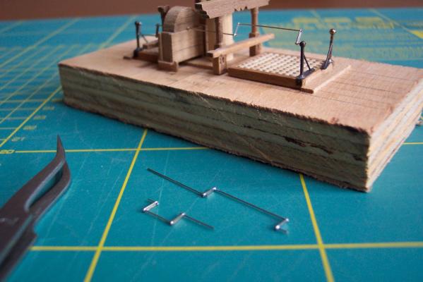 I then tried a dry assembly in the actual waist area to make sure all was well. It is getting very tight in there which will make rigging a bit tricky. Also having one of the pumps open may not be a good idea in this small space. I will have to give this some more thought.You may notice all the cranks hang downwards - this is because they are not as yet fixed so gravity is taking over.
 There are a lot of items in the waist which have not been permanently fixed in place yet. These are waiting on the canon rigging to be completed. Perhaps I should get stuck in to that now - I have put it off long enough.
 -
ZyXuz,
Very nice work. The forecastle area is looking superb.
I will be doing my belfry soon so this is very useful. I always felt the Corel belfry was on the large side.
-
Mike,
An idea that I picked up from an ex tool maker is to clamp the long sanding device in a vice or on the bench then move the item to be sanded along the top. I have some long straight files which I clamp in to my vice for this purpose. One thing to watch out for when doing this (teaching granny to suck eggs here probably
) is that the resistance from the sandpaper is backwards along the underside of the piece but your forward pressure to move the piece is along the top. This tends to give a rotating force that puts more pressure on the front edge of the piece that can, if not counteracted, result in tapering at the front of the piece.It is a great way of doing your nails at the same time.
-
Mike,
That is a nice model that you have found. From that I think slicing the Corel Unicorn body in half then thinned and stuck on the sides of the stem might just work.
I like the open bulwark on the quarter deck which is what I intend to do by adding a rail. It will not be as high above the solid part of the bulwark as it should be but to me will look better. There are a lot of nice ideas that can be gleaned from his photos.
I am not sure about his davits at the rear. He also has a dolphin striker which according to Lees did not come in to use until 1794.
Did you notice that in one photo is shows a real compass in the binnacle!
I also notice he has the tiller above the quarter deck. Nice. -
Mike,
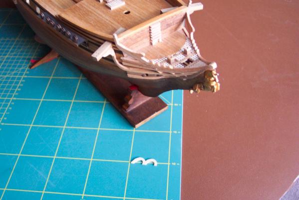
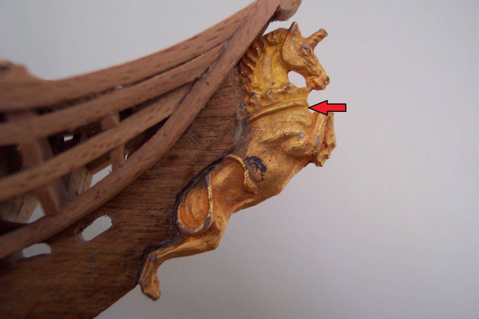
I agree with you on the headrails. I made them as per the Corel instructions with 3 x 3mm beech which (along with the Corel fanciful shape) makes them look far too clunky. The figurehead is too low and is positioned more like those on later larger ships. I did this part of the model a long time pre MSW resulting in a less than satisfactory piece of work.
I shaped the stem to fit the figurehead. A also filed of some of the detail down the rear of the figurehead. I fixed the figurehead with 2 part epoxy to ensure that it stayed in place and it also fills the slight gaps. I will paint the figurehead at a later date including covering up any exposed epoxy.
I have added a close up (groan) of what I did. The horn was snapped off when I first got the kit so I have yet to replace it.
I contemplated cutting a slot in the back of the figurehead but didn't for a couple of reasons. At that time I did not have the milling machine. A slot cut between the rear legs to suit the stem would leave the legs very thin. The figurehead neck is narrower than the stem.

I think if I was doing this part again I would:-
i) make a much finer set of rails which didn't protrude above the stem
ii) using a piercing saw cut the figurehead's head and neck off along a line below the crown (marked by the red arrow in the photo)
iii) either slot the remainder of the body or cut the body vertically in two then thin the two sides down
iv) fit the body either side of the top of the stem
v) attach the head to the top off the stem
vi) only have one slot for gammoning!
Correction of this on mine was one of the items that I decided would take the model past the point of scrap and start again.


HMS Unicorn by ianmajor - Corel - Scale 1:75, 1748 to 1771
in - Kit build logs for subjects built from 1501 - 1750
Posted
Thank you all for your likes.