


ianmajor
-
Posts
784 -
Joined
-
Last visited
Content Type
Profiles
Forums
Gallery
Events
Posts posted by ianmajor
-
-
Gosh Mike,
That has a huge amount of useful detail including position of and height of belfry and swivel gun mountings. A few hours careful examination will reap many rewards.
At first glance a couple of things intrigue me. The stove flue appears to be slightly foul of the fish davit position (assuming the span shackle that would be used was on the far side of the flue) and the hawse holes appear to be foul of one of the head timbers.
-
John,
Your galleries are fabulous. I am rather jealous of them.
 They complement a very nicely made hull.
You also have a good way to make the spectacle plate. A very neat piece of work.
BTW - it is not patience that keeps me going - just being a half wit that does it.

-
Piet,
As ever - absolutely fascinating.
-
Mike, great work. As you say the clamp is not a good looker but very functional - which at the end of the day is all that is required - and therefore it is perfect.
The rudder is a big improvement over the simplified Corel version. I like it.
One thought on the first and next couple of bulkheads. The Corel interpretation is to have them producing an outward curving bulwark above the fore deck. Looking at the Chapman diagram my interpretation is that these bulwarks should be straight up. Have a look at the line Q on the right of the rear view of the plan (which corresponds to the first Corel bulkhead) and O and L (which more or less correspond to the next two Corel bulkheads).
Shaping the first three bulkheads so that they are straight up above the foredeck level will make it look right IMHO - it will also make adding detail in this area at lot easier in the later part of construction - with which I struggled on mine.
-
I thought you might be interested in how I make the split pins. It is very easy.
I don't twist the legs together for a variety of reasons.
If you are not careful when doing the twisting one leg remains straight and the other twists around it making a very insecure loop. The act of twisting the wire fatigues it and if the legs are over twisted to get a nice tight eye the wire will fracture between the eye and the legs. This may not show up until after the eye is in use.
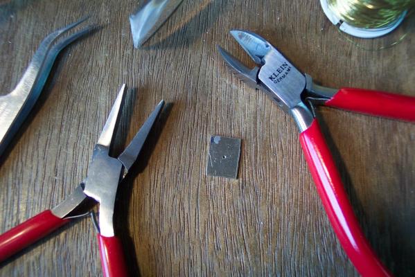
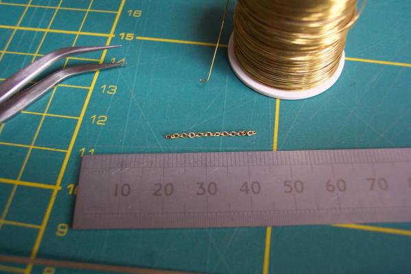
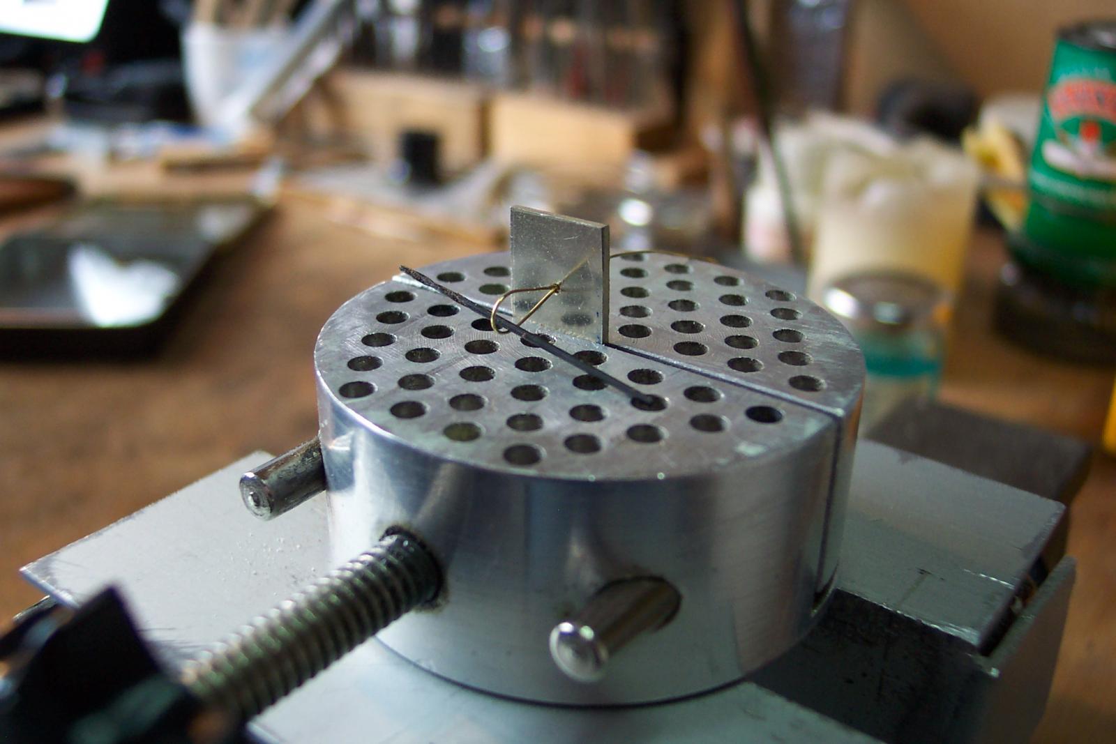
To make homemade split pins all you need is a die, some fine pliers, cutters and an old drill bit with the required diameter of the split pins eye.
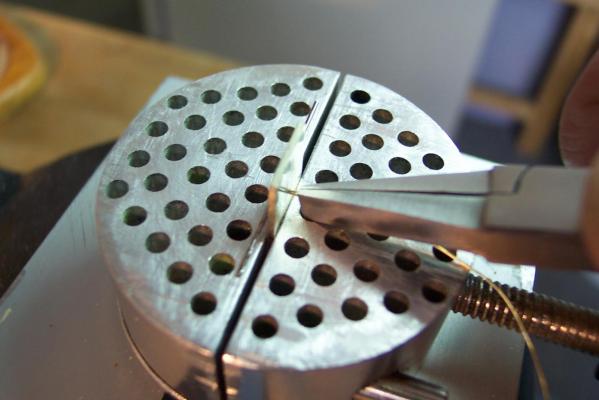
The die is a scrap piece of metal, in my case a 1mm thick piece of NS. Somewhere near the centre drill a hole which is twice the diameter of the wire that you are going to use - the wire will pass twice through this hole. On one side lightly counter sink the hole.
Clamp the die in a vice. Pass the wire through the hole from the non countersunk side. Bend the end of the wire in to a loop then pass the end of the wire back through the hole in the die. Put the drill bit in the loop of wire. If the wire is on a reel there is no need to cut it off at this stage.
(Poor photo replaced).

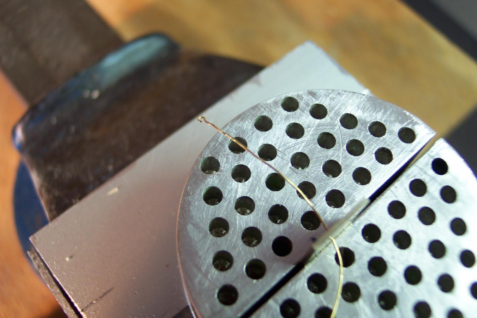
Grab hold of the two wires on the non countersunk side and pull firmly. To avoid crossing and fracturing the wire keep the drill bit horizontal and the gap between the jaws of the pliers vertical.
If you have pulled firmly enough the wire will have closed around the drill bit. You can help this by pressing the loop towards the hole with a piece of wood.
Trim the legs to length. For a split pin cut the legs a different length. This will make the legs easier to feed in to the hole in the model. With the pliers gently close the legs up parallel to each other.
If you want a hook hold one leg only on the non countersunk side of the die, waggle it side to side, then pull it sharply to one side to break it off as in the picture.

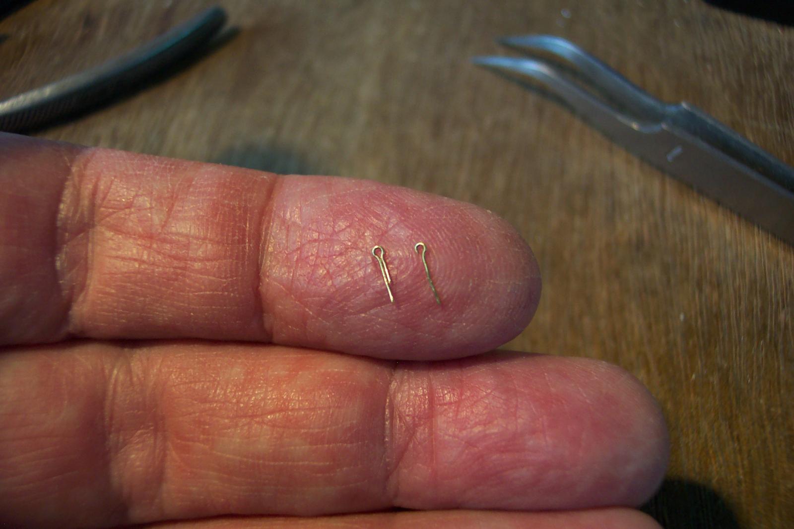
The result one split pin (slightly larger than the ones used on the chain) and one hook. Each took about 30 seconds to make.

- Ferit, dafi, Blue Ensign and 4 others
-
 7
7
-
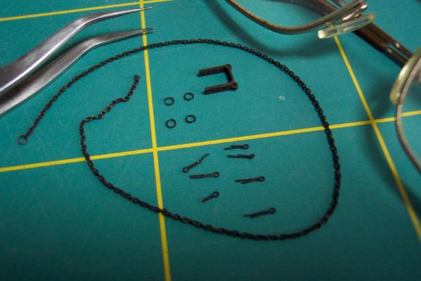
I have completed the length of chain required. In the end I produced one with about 240 links. In fact once I got me eye in it didn't take long - about 15 minutes to create 30 links and then about 15 seconds each to add a link to the chain. Need the jewelers lens to do this.
Nenad, I suggest you rope in your local knitting circle if you want to produce large quantities of chain this size.
I also produced a few homemade split pins with 0.6mm eyes and a few slightly larger round links to hook the chain to the spectacle plate.
All these items were then blackened.
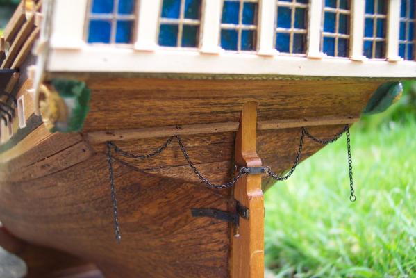
They were all then fitted in place. I put a baton across the stern in which to mount the split pins. I looked at various models and actual ships to try to decide where to position it. The incorrect stern shape and lack of stern post required somewhat of a compromise. The outer ends of the chain are just hanging for now.
- Carlmb, Piet, Landlubber Mike and 8 others
-
11
-
Mike,
Your Badger looks OK to me. I am sure Stockholm Tar would have picked you up on that point earlier if I hadn't spotted it.
I find it interesting that there seems to be a lot of effort goes in to the research of ship's structures for kits but flags don't get the same level of consideration. I saw a kit for one of King Henry VIII's ships with a Union Flag on it. Henry VIII had been dead for some 60 years before King James VI of Scotland (who also became King James I of England) instructed the navies to use the combined Scottish and English flags from 1606 on. It did not become the national flag until the act of Union of English and Scottish parliaments in 1707.
Another horror that I saw in a kit was an ensign with the Union Flag upside down in the flags first quarter. Sadly these days I think about 50% of the UK's population don't know the correct way up for the Union Flag.
 When I was at primary school the headmaster gave me the responsibility of raising the schools Union Flag on flag days. Flying it upside down would be rewarded with a beating - so I got a bit obsessive about it.
 -
John,
I see in your comments in Mike's Unicorn log that you are thinking about adding a false deck layer to raise the quarter deck level but only as far as the front of the Great Cabin (if I understand correctly). I also considered this. The only reason that I didn't was that I had already cut the port holes for the cannon on that deck so a false deck would have made them too low.
If you are going to do this I think it would be worth considering extending the leading edge of the false deck to the waist area where the deck would have stepped down on the actual ship. The challenge with this approach is to hide the leading edge of the original deck. The bulwarks would need to be raised in height but this is OK since the Chapman plan shows the Unicorn with open bulwarks. An added rail would be spot on.
I think a difficulty with the false deck leading edge being at the front of the Great Cabin is that it will occur in the midst of deck furniture such as the wheel.
-
Mike,
This is a very nice kit - very tempting.
One thing you might consider when doing your own improvements - the flags supplied are from the wrong period. Your photos shows the Union Flags with red diagonal lines. This is the form of the Union Flag after the Unification of Ireland (with the rest of the UK) in 1801 - the Parliamentary Act of Union passed in to law in 1800. The red diagonals are derived from the flag of St Patrick the patron saint of Ireland.
- FrankWouts, Landlubber Mike and egkb
-
3
-
Mike,
Your concentrating on Pegasus will remove the risk of you overtaking me on my Unicorn and putting mine to shame.
-
Mike,
I await developments with bated breath.
I think this is going to be a good read.
-
Nicely done Mike. Who need kits anyway!

-
Mike,
Yes it is indeed for the rudder chains. It is worth noting that the same shape of metal work but with plain glass in the holes was mounted vertically over the fireboxes of steam locomotives in front of the crew and was also called the spectacle plate. And of course with lenses in we stick them on our heads and call them spectacles (though now most people call them glasses). My 3 year old granddaughter told her teacher that "Everyone wears glasses except my granddad. HE wears spectacles."
If you were here I suspect it would only take me 5 minutes to teach you what you don't already know. The rest of the afternoon would be better spent wandering around the nearby Derbyshire Peaks.
BE, below some chain that I produced using the info that you pulled together in your Pegasus log. Based on 1 inch bar (scale 0.25mm) and 4 inch links (1mm) I used 28 gauge brass beading wire (0.3mm diameter) and a 1mm by 0.4mm cross section former. I used the usual method of wrapping the wire many times around the former then used a piercing saw to cut along the links to separate them. After each turn I used the pliers to gently squeeze the turn to ensure an oval shape. The result after several hours work was 2.2cm of chain (about 22 links). I need about 160 links.
To be honest it looks no better than some of the cheap jewelry that Woolworths used to sell (shame they went bankrupt).
I have only one decent pair of fine tweezers and to do a quicker more efficient job I could do with two. The small pliers are rather too large for this job.
- Piet, mtaylor, Landlubber Mike and 1 other
-
4
-
John,
Thank you for putting the information together. You appear to have a very pleasant nautical themed room there with some very interesting pictures.
The models also reveal a very skilled (and generous) model maker. I look forward to developments on your Unicorn.
-
Hello John,
Excellent to see your Unicorn in a build log. It looks lovely.
There is definitely a ship theme in your room, with the picture on the wall plus the Unicorn is sat on the display case of another ship. I can't find a reference to this other ship model. What are its details? Do tell us about the pictures as well.
-
Guys, Thank you very much for the kind words and suggestions. I think I am swaying towards the "boxwood" effect for the castings. I will have to get my paint shop organised.
Gianni, I would have liked to put a name below the lights on the stern. The problem I felt about blanking out the lowest row of panes was that the lights would then be too high with the tops above the quarter deck line. I spent a fair bit of time debating this point before I started!
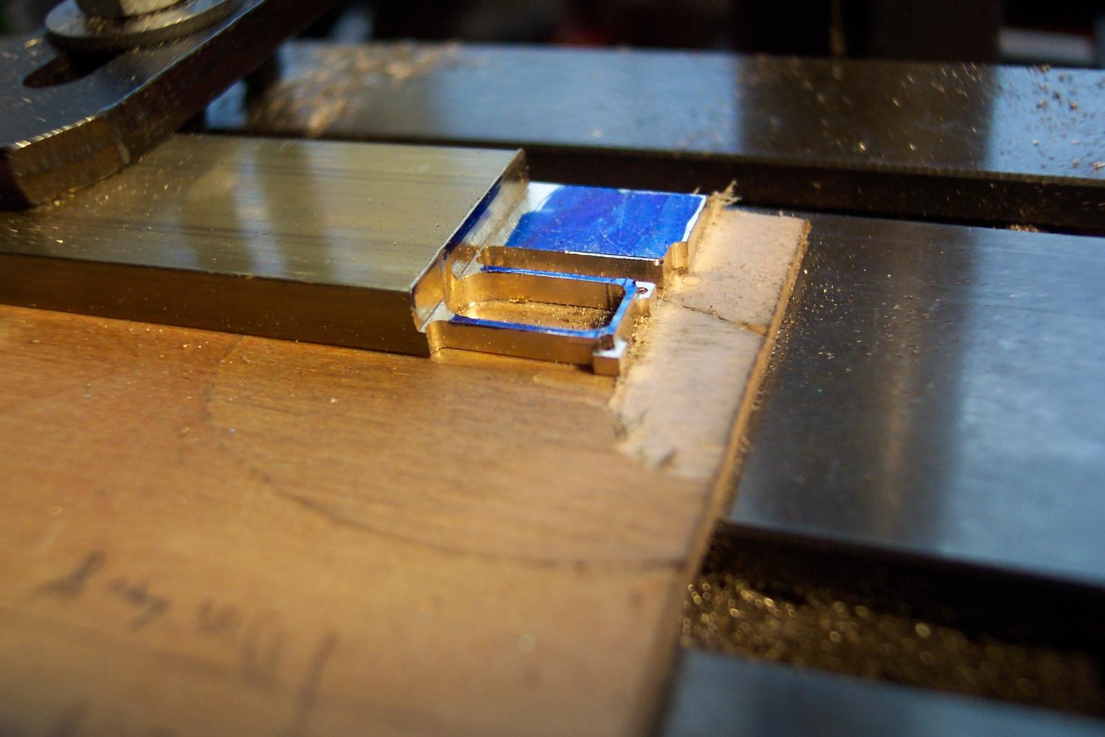
Well I have been doing a bit of milling to produce a spectacle plate for the rudder. I clamped a suitable piece of brass to the mill table. First I milled its thickness down to 2mm. This is probably too thick but the Corel hinge parts are quite wide (there are only 3 sets) so I felt this thickness would be consistent.
Next up was to run the milling bit across the end to make it square, then drilled two 0.8mm holes 6mm apart across the piece. Then with a 5mm milling bit lined up with the mid point of the two holes I cut out the central slot. The rest was shaped using a 1.5mm mill bit including squaring up the central slot. Also the eyes were thinned down. The result is in the first image.

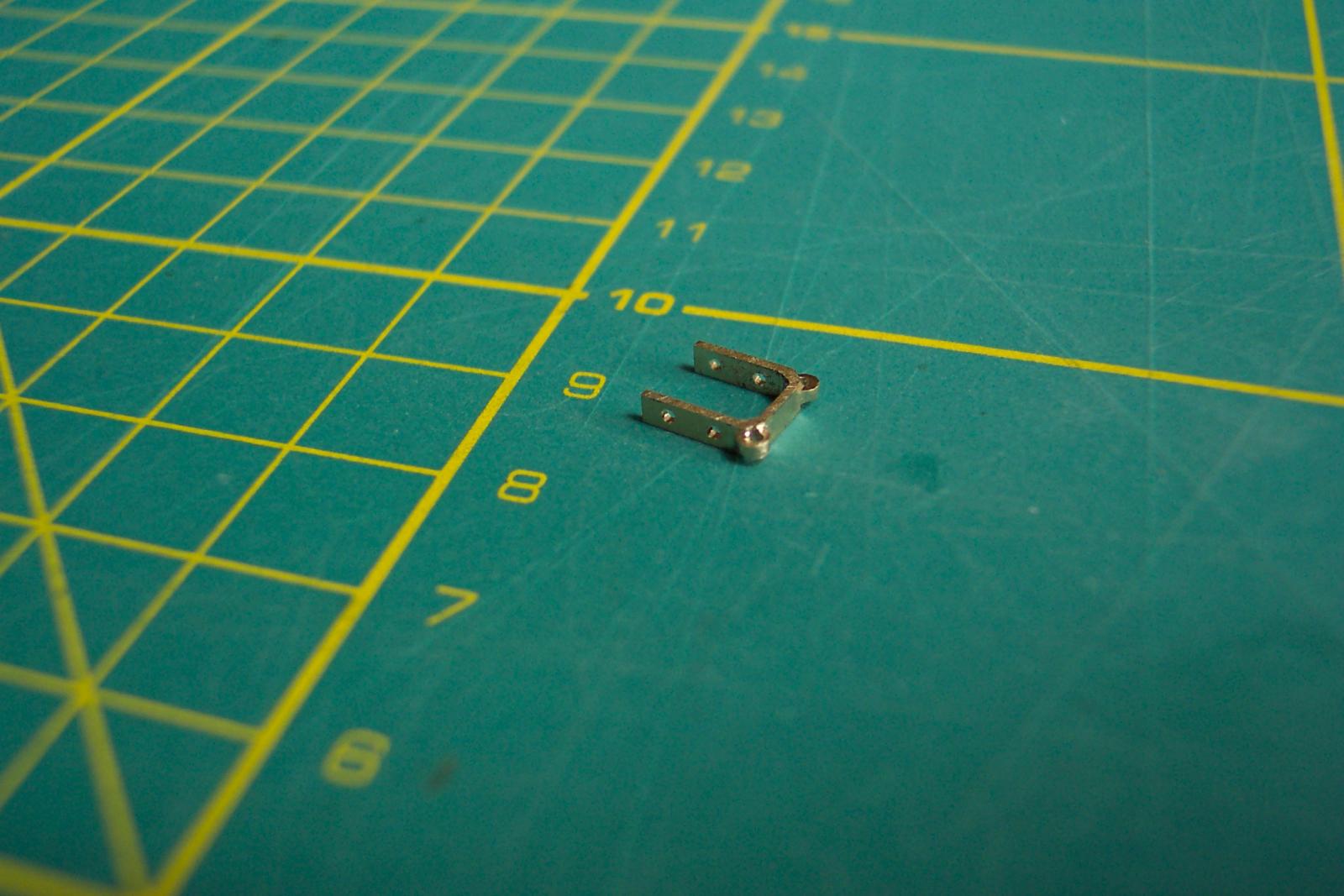
The brass was turned over and the eyes were thinned from the other side. The spectacle plate was then parted off giving 7mm long legs. Each leg had a pair 0.8mm holes drilled in them. The shape was then improved by hand filing.

Next was a test fitting to the rudder.
Before fixing this in place I will make some chain with 1mm links (BE has some useful info in this area in his Pegasus log page 56 entry 834 (link) . I am also contemplating a rudder coat. Hum.
-
Mike,
My children got my Unicorn involved in the intergalactic wars with the Daleks. A robust front end was a necessity. It took the pounding very well.
On the relationship of the hawse holes to the main wales I had a look around. Each of the models that I looked at had the centre of the hawse holes in line with the lower edge of the gun ports on that deck.
I also had a read of Flynn's thesis on the Pallas (link). I find it useful since it pulls together information from various sources. On page 36 he writes about the main wales:-
"Ships like Pallas were planked both inside and out. The first and most important part of the planking to be fitted was the main wale, a belt of heavy strakes placed between the waterline and the gun ports. Its primary function was to add longitudinal strength. The main wales ran parallel to the line of the sheer rather than the decks. The lower edge tapered towards the ends of the ship.(81) Wales were made of the very best quality oak cut 25 ft. (7.62 m.) long and 7 in. (17.8cm.) thick. The main wales on both Diana and Pandora were at or near the dead flat of the sides (Fig. 14). All sources agree that the main wales on 36- to 38-gun frigates were composed of four strakes, 38 to 43 in. (96.5-109.2 cm.) wide, and 5½ to 7 in. thick.(82)"
There are two citations in there which expand to:
(81) Falconer, Universal Dictionary, 331, Fincham, Outline of Ship Building, 29, Goodwin, Constructionand Fitting, 53, Steel, Shipwright’s Vade Mecum, 140-141 and Murray, Treatise on Ship-Building, 209.(82) Anonymous, Shipbuilder’s Repository, 268-69, Murray, Treatise on Ship-Building, 205, Goodwin,Construction and Fitting, 53, McKay and Coleman, Frigate Pandora, 69 and White, Frigate Diana, 61.
The main wales being below the gun ports suggests to me that the hawse holes will be above the main wales.
He is describing 36 - 38 gun frigates which are larger than Unicorn but I would guess the smaller dimensions he quotes for the wales would apply.
The Corel version is only to apply two fairly wide thick strakes as the main wales rather than 4, but I suspect this is one of the areas that the kit construction is simplified.
- Landlubber Mike and mtaylor
-
2
-
Mike,
The figurehead will look much better where you propose to fit it. The Corel position makes it look too delicate to me. Your position gives it a robust feel - you could have confidence to ram another (smallish) ship with it.
As a matter of interest, have you seen Dan Vadas' latest work on his Vulture? His log is currently a blow by blow description of making and fitting the headworks. Perfect timing for your design work. His description starts on log page 84, entry 1253 (link) . I think your questions will be answered there, despite the Unicorn being a beakhead and Vulture isn't.
- Landlubber Mike and mtaylor
-
2
-
Mike,
That is looking very nice.
I think your approach to the bowsprit is absolutely spot on. Unfortunately I did not take your approach and I remain concerned about attaching the bowsprit on my Unicorn in the near future, particularly when I am doing the gammoning.
-
-
Mike and John, Thanks for your input. You have me thinking. A third option that sprang to mind reading your comments was to paint the castings a sort of box wood colour - I could then pretend that I carved them myself.
 Perhaps not.
And everyone thanks for the likes.
John. In answer to your questions.
I was originally going to leave the transom and gallery detail until after I had fitted and rigged the guns on the main gun deck. I changed tack on this when Mike pointed out his experience of previously fitted guns popping out of place when attempting to do work on the hull. So I decided to finish off the exterior before rigging the cannon. The fittings on the quarter and fore deck will be finally fixed after I have rigged the cannon. My main reason for doing this is that I need to attach some beams under the edges of these decks on the leading and trailing part of the modified waist area. I can't fit them until the cannon are in place, and I can't clamp them with some of the fore/quarter deck items are in place.
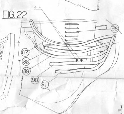
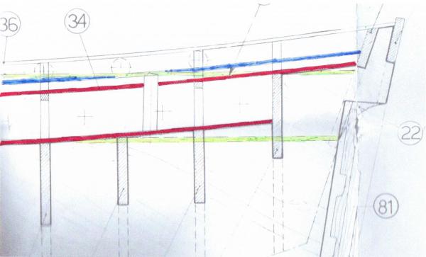
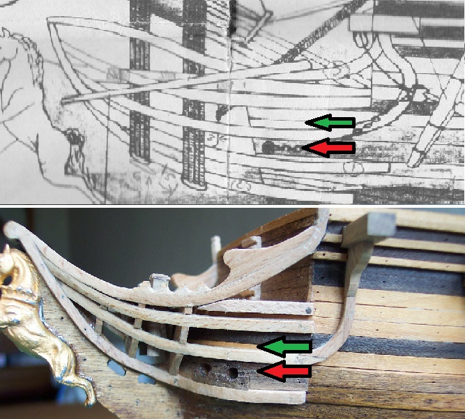
IMOH the hawse holes are too low on my model. I have drilled them as per the plans. The following images shew the model and the plans. The red arrows point to the hawse holes and the green arrows indicate the level of the upper (main gun) deck. The images also shew that the main diagram only has one hawse hole per side (and chain!) where as diag 4, correctly, shews two hawse holes.
You may also observe that I have a gaping joint to fill and that the plans are starting to look as careworn as I do.

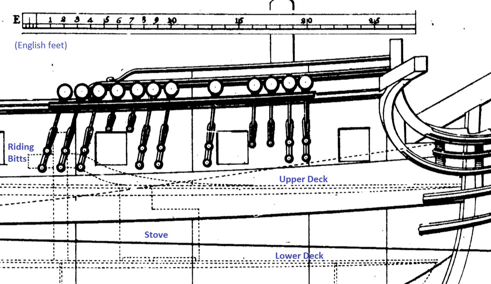
The next image is an extract from the Chapman diagram that I annotated as part of a discussion that I had with Mike. You can see the riding bitts on the upper deck although the hawse holes are not marked. (Note also the stove on the lower deck - that must have been cramped!)
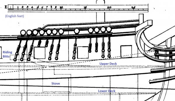
The hawse holes should open on to the same deck as the riding bitts. So on the model they should be higher - probably in line with the lower piece of ebony.
If you have a look at Chuck's Winchelsea log page 1 you will see some images of his plans. If you click on them they will open up to a slightly larger image. Look at the cross section part of the diagrams and you will see where he has the hawse holes with respect to the upper deck. The Winchelsea is a slightly larger design was based on the Lyme class.
-
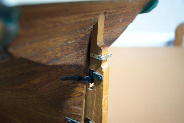
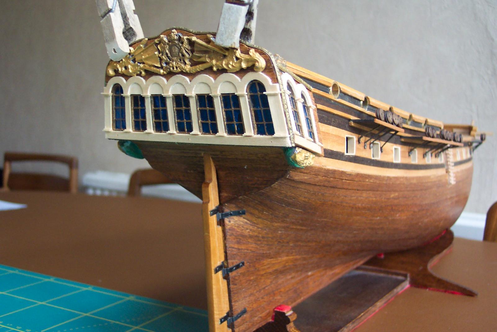
A bit of progress around the rear end. I have now added arches, pillars and sills around all the lights.
I will soon be re-attaching the thinned, rear casting. Before doing so I am trying to decide whether to paint it as per John's version above or whether to 'guild' it. Will the guilded version be more in keeping with the natural wood effect of the rest of the ship? I am not sure. Below is a photo with the casting held temporarily in place with clothes pegs. Any views on this point?

Also I think the galleries should have been mounted about 2mm lower to make the lights line up better. Something else for others to look out for.
The arches and pillars also unfortunately highlight the higgledy-piggle nature of the glazing bars on early Corel plastic casting.
- UdoK, petervisser, Mirabell61 and 12 others
-
15
-
Mike,
Nice work. I can already see the overhang at the rear is much more in line with the Chapman diagram than the Corel interpretation. Excellent!
Are you going to chop a piece out of the keel part so that you can represent some of the lower deck?
-
John,That transom looks great. I need to paint the castings. I am interested in the way you have painted the flags. I can see you have produced the Scottish Saltire on the left and the English cross of St Goerge on the right. I had been wondering what flags to paint there. Did you get that arrangement from a particular source or is it your interpretation? There would not be the red diagonal cross of St Patrick since that only appeared on British flags after the Unification of Ireland in 1801.On mine I am thinking of blocking off the upper panes as per the photo of one of the contemporary models that Mike has in his log (and comparing with ZyXuz's). The castings for my early version of this kit are different to the later ones. The lights/windows in mine are blue plastic with the frames molded in to them. The blue plastic actually goes right across the rear of the plywood that supports them.On the bulkheads in the waist area. The upward extensions of bulkheads 6 and 8 are pretty obtrusive. I have covered them with planking to camoflage them as much as possible. I will be making a 28ft pinace to sit above the waist area which will hide them a little.If I was doing this all again I would cut those extensions off so that I could have the gangboards only 2 planks wide as they should be. This would require some new knees to support them.Bulkhead extensions 4 and 10 are also visible but not quite so bad so I would possibly consider leaving those.I would certainly try to raise the quarter deck a few millimeters to get the step up from the waist area. Have a look at Dan Vadas' Vulture log entry 932 (here) for inspiration.I have discussed the raising of the quarter deck with Mike. The deck line as per Corel does not match the deck line as per Chapman. See the image below:
 This is a copy of part the Corel diagram 2. I have marked the Corel deck lines in red (the upper one is the quarter deck, the lower line is the upper deck). I have also marked the Chapman deck lines in green. As can be seen the Chapmam decks do not sweep up as much as the Corel ones. The Chapman quarter deck is also higher near to the waist.To adapt the kit to the Chapamn lines would require fairly major modifications to the keel piece and to bulkheads 12, 13 and 14. It would also affect the line of the gun ports.What about leaving the upper deck as is and changing the line of the quarter deck to match Chapman? Mike and I rejected that approach because the line of gun ports on the upper deck would no longer be parallel to the line of the gun ports on the quarter deck.If I was doing this again and opted not to alter the upper deck line, I would have raised the quarter deck uniformly along its length by a few millimeters - as per the blue line. The quarter deck ports would break through the tops of the solid bulwarks, but they do on the Chapman plan.I will be adding an open bulwark rail and supports for swivel guns on my quarter deck.It is also worth noting that the companion way that I have in front of the capstan would be better behind as per the Lyme diagram in the NMM. I have had to foreshorten the rear cranks of the pumps due to them being cramped by this companion way.
 Main thing to watch out for, if you want to do this, is the positioning of the beams strung between the bulkhead extensions.(Time for Mike to drag me back to the realms of reality - AGAIN. )
- Landlubber Mike and dafi
-
2


HMS Lyme (1748-1760) by Landlubber Mike - bash of Corel Unicorn - Scale 1:75 (CLOSED TO START SCRATCH BUILD)
in - Kit build logs for subjects built from 1501 - 1750
Posted
Very nice Mike. I love the idea of the companionway going down in to the (false) lower deck. When the ship is completed this feature will draw the viewer's eye and intrigue - where does it lead ............