HOLIDAY DONATION DRIVE - SUPPORT MSW - DO YOUR PART TO KEEP THIS GREAT FORUM GOING! (Only 53 donations so far out of 49,000 members - C'mon guys!)
×


ianmajor
-
Posts
784 -
Joined
-
Last visited
Content Type
Profiles
Forums
Gallery
Events
Everything posted by ianmajor
-
 Hello Mike, Sorry for not replying earlier - have been it bit distracted of late! The deck layout of the Venus does look similar to the Coral Unicorn offering. I always felt the kit deck was from a later period and not very British(?). How old is the Renommee kit? The Coral Unicorn is 1974 (pre Web days). I think when kits were designed in those days they were done as cheaply as possible and with the view that most people building the kit would not have easy access to the source plans/information so "would not know the difference". Or is that heresy?
 -
Hello Chuck, Drop me a PM so that we can exchange email addresses. I can then use your email address to give you access to my share. You will find the sheet you require there. However I don't think much of Corel's idea of how the headworks should go together. Even with all the instructions it is not clear and produces a poor result. I suspect all the Unicorn builders will agree with this view. I would suggest having a look at Dan Vadas' Vulture log. He gives a very good, illustrated, step by step description of how the headworks go together. The start of his log covering the head works is <here> . Using Dan's description you should be able to produce a good result without machine tools. Good luck.
-
Chuck, I have my plans scanned in on a share drive. If you drop me a PM with your email address I can give you access to them. One thing my instructions are version 1. A later version does exist but sheet 4 is unchanged I believe.
- 51 replies
-
- 2
-

-
- first build
- corel
- (and 1 more)
-
Ed, Beautiful work on the anchors and great to be able to see you next to your developing masterpiece.
- 3,618 replies
-
- 4
-
-
- young america
- clipper
- (and 1 more)
-
Piet, Rats - I take a few days away from MSW and miss your birthday. A belated best wishes and I hope to see much more of your inspirational work to come.
-
This has me interested. I also note that ggrieco is looking in at the moment. With Gehard(Vienna) building and Glenn (ggrieco) in the background I am getting some very high quality vibes!
-
Glenn, Fabulous. A piece of machinery that I would be mesmerised by when watching it turning over slowly.
-
Hello Tristan, I see from your intro that you are from lovely Devon. I hail from further up country. I don't know how far you got with your Victory but I imagine you did at least some hull planking. If you look in the "ship modeling articles and downloads" you will see useful articles on planking. Worth a look if you haven't already done so. Best of luck with this build.
-
Paul, that looks a very fine piece of work that you have done. You have identified Gill Middleton's log which I regard as one of the finest on this forum. If you have not already done so I would suggest having a look at Dafi's Victory <here> . It is based on a Heller plastic kit which may not immediately seem relevant to your wooden build but he has done a lot of research into the detail of Victory's construction which he documents here. He also creates various tableaux with figures to show how the ship was operated. If nothing else it is a fascinating read. Good luck with the rest of your build.
-
Hartmut, That is very impressive. Nice work.
-
Pat and Piet, thanks for looking in and all the likes. Piet, re hardening the mild steel - I only use mild steel for infrequently used tools that will be used on soft(ish) wood which I don't bother hardening. Perhaps I should have mentioned hardening here. For tools that require more demanding use I use tool steel which I harden and temper. Pre-empting the question on how to harden steel (not from Piet) there is a good description <here>.
-
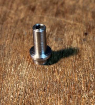
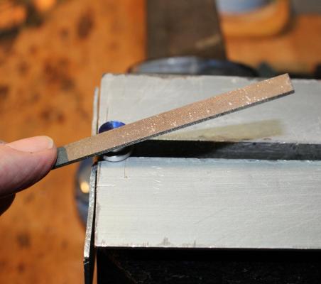
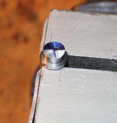
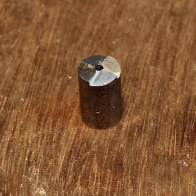
John and Mike, thanks for your replies. John looking at your suggestion I could push the "Option 1" front forward. I was looking to keep the distance between the front support and the rear scroll to be the same as the distance between the two scrolls. As you point out that is not the case with the NMM 6th rate model so pushing it forward should do the trick. An interesting thing about the NMM model is that it is not the usual Admiralty type. The NMM notes say that it is ballasted with a lead keel suggesting that it is a sailing model. I look forward to seeing how you get on with your fresh supply of pear wood. I love the smell of wood freshly cut from fruit trees. Takes me back to my Father's plum orchard. Looking back at the swivel posts I thought you might be interested in how I "turned" the circular top part. I made a rose bit to do this. They are not hard to produce, only needing a drill press, bits, files and some mild still rod to make. Below are some photos of how I did it. The first four are of an experimental one for use in a holder but show the basic process. I had a 2cm piece of 10mm diameter mild steel to hand for this. I filed the ends square then drilled deeply the centre of the end. The diameter of this hole determines the diameter of (in this case) the end of the post. I then drilled the centre of the other end with a larger bit most of the way through leaving a couple of mm's length of the smaller diameter hole. This is to stop the work binding in the hole particularly if using a rose bit to produce dowling. I then used a fine blade saw to cut a shallow cross on the small diameter hole end. The middle of the cross being the centre of the hole. This was to act as a guide to filing. Next I used a permanent marker to blue the end. Then with the rod in the vice with the small hole upper most and I filed the ends with the file at the angle shown in the next photo. The file was kept to the right of each saw cut. I continued filing each face until the blueing between the file mark and the next saw cut just disappears. The next photo shows two faces approaching this point. When all four faces have been treated this way you are ready to go. Here is the one I used on the posts. The way I used it was first to cut around the post, using a knife, at the point where the round part of the post meets the square part - this acts as a stop cut. I bevelled the end of the post very slightly then simply used the rose bit like a pencil sharpener. (Cue gasps of horror from the guys who do things properly). Actually, when I get around to it I am going to make a holder for my rose bits to go on to the tool post of my lathe. I will be able to make fairly long lengths of brass and wood doweling in a variety of sizes. Rose bits have been around a very long time. Another example of their use in MSW can found in <Garward's Montanes log> . There he makes the end of the cannon axles by putting the rose bit in the lathe chuck and mounting the axle in the tool post. Unless disaster strikes I should have a set of 26 rail supports machined up by tomorrow - that or a pile of splinters.

-
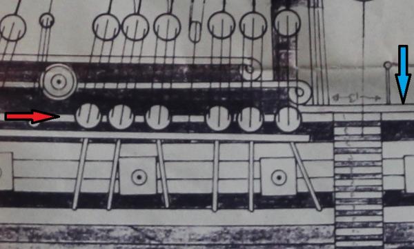
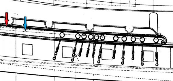
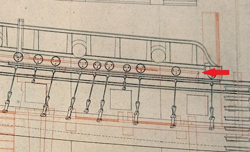
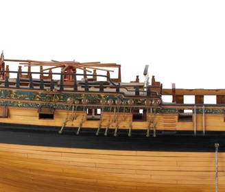
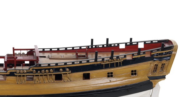
Mike/Mark, again thanks for the input. I have to admit I have put off this part of the modification for some time. I have been debating with myself at length about the best compromise. Mike, you are right about the rail in option 1 ending shy of the leading edge of the quarter deck (drat, I thought no-one would notice), this is illustrated in the two top views below. I am now hooked on using 3D modelling rather than scraps of paper for my modification plans. Option 1 top view Option 2 top view I gazed long and hard at the various plans. I had made the end of the bulwarks as per the Corel plan. This resulted in the two scrolls at the fore end of the bulwarks being very close together when compared with other plans/models. Below is an extract from the Corel plan to illustrate this. The Corel deck follows the line of the trim marked by the red arrow. The unmodified quarter deck front edge is indicated by the blue arrow. Now back to the wood cutting........ Compare this with the Chapman diagram on which the Corel kit purports to be based. Below is an extract from that plan. The vertical position of the quarter deck is marked by dotted lines. My interpretation is that the pair of lines marked by the red arrow show the thickness of the deck planking and its height along the centre line of the ship. The single dotted line marked by blue arrow is the height of the deck at the bulwarks. I measured up and the solid bulwark is about 2'6" above the deck - which seems low to me. There is no indication of a rail which I believe there should have been. It is also unclear exactly where the leading edge of the quarter deck actually is - it sort of peters out in the middle of the main mast. In the original of this plan Chapman has another ship alongside where these details are more clearly set out. Next is an extract of the Lyme plan showing leading edge of the quarter deck indicated by the red arrow. This shows the open rail terminating a roughly the same point. The above three make an interesting comparison. When in doubt, in these circumstances I consult Chuck's Winchelsea or in this case look at photos of the Winchelsea model held by the NMM. Below is an extract from one of the NMM photos the original can be found <here> . Although the rail(s) are more complex than my offering a close look reveals that the high rail stops short of the leading edge of the quarter deck. So there is a precedent to my having a "short" rail - well at least that is my excuse. Now - back to the wood cutting.......

-
Mike, Pat and S, Thanks for your input. You have helped me to decide on option 1. For the front curved part of the rail I have turned a ring of boxwood 8mm outside and 4mm inside diameter which is 3mm wide. This will be cut in to quarters to make the curve. Mike, the rail stands just over a scale 6ft above the quarter deck so would give adequate protection. It looks low because the Corel quarter deck is too low IMHO. I have pondered the gun port rings before and agree that they don't seem to add anything structurally. Many of the ships prior to the mid 18th century seemed to have had circular decoration around the gun ports even where the ports were square. I was wondering whether the rings on Unicorn/Lyme were primarily to support such decoration. None of the plans give any clues on this.
-
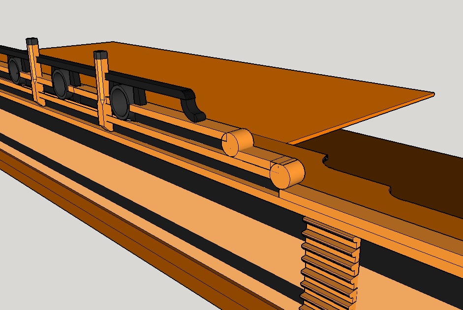
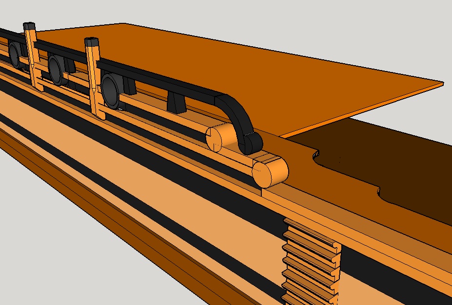
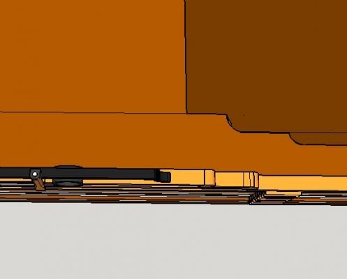
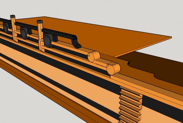
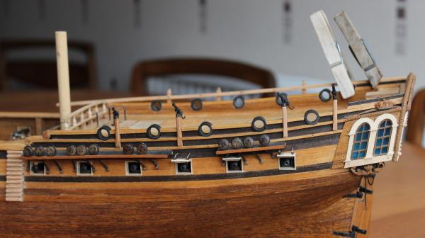
I am making steady (slow you may say) progress on the open rails. I have fitted the 8 swivel posts around the quarter deck. For the rail I had bought some 5x2mm beech strip which would make it the same width as the cap. Looking at BE's <Pegasus> and Dan Vadas' <Vulture> I realised the rail should actually be narrower. So I ripped it down to 3x2mm. Since the gap twixt cap and rail would not be as wide as Pegasus/Vulture I looked at other models for inspiration on supports and for the shape of the ends. The nearest was a contemporary model of a 24 gun sloop at the NMM which I am working towards. Below is an extract from a MNN photo the full version can be seen <here> . I cut mortices in the rail to accommodate the swivel posts and had a trial fitting. To spport the rail at the rear I have fitted a length of 2x2mm beech stained black on top of the cap. Looking at the rear of the rail in the photo I think I could attempt a tafferail which would have to sit on top of the quarter rails. If I go this route it will make it easier to mount a stern lantern. The question then comes up about the shape of the leading end of the rail. I have been following thibaultron's log on "going From a 2D Drawing to a 3D Printed Part Tutorial" <here> which inspired me to have a crack at using Sketchup to look at the rail options. After a couple of evenings playing around I came up with the following two 3D plans. The first is in the style of the 1740 24 gun sloop, the second is in the style of a reduced version of the Pegasus/Vulture rail. I think I am biased towards the first one. Any views on this? My Sketchup rendition is a bit ropey but not too bad for a first effort. My wife watching me using Sketchup for the first time reminded me that I had sworn to turn my back on technology during retirement. As a result she says my epitaph will include the phrase "A Failed Luddite". I gave me such a severe attack of the giggles that any further work that evening was abandoned.


-
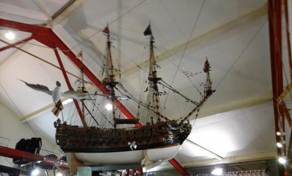
Nenad, Mark, Piet, BE and Pat thanks for the kind words and all the likes. I have been out and about recently. One journey took me to Preston (UK). The docks there have mainly lost their original industrial purpose and have now been redeveloped as a leisure marina. We usually go to the Marina Cafe/Chandler's. In there we are surrounded by boating goodies whilst having a pot of tea. Hanging from the ceiling is a model of a ship that is 7ft long...... It was given to the Cafe by the builder's daughter. According to an attached plate it is called the Elizabeth after that same daughter rather than an actual ship. It is supposed to be based on "Nelson's Victory" but the rigging suggests an earlier ship. It is very well made but has a few oddities such as the channels are too low down. Worth a look at if you are in the area.
-
Joe, That is shocking. The packaging that you describe would not survive any postal service in the world.
-
Up to your normal standard of work and research Dafi. Wonderful stuff. By the way, mentioning Bristol, have you ever visited the place? If not it is well worth a look. Apart from Brunel's SS Great Britain there are other interesting places to see. I was based there for a while and was fascinated by the "nails" that still stand in Corn Street near the docks. These were waist high pillars on which deals were struck over cargo and so on. They have given us all sorts of phrases about deals being "paid on the nail" or "nailing it".
-
Moony, I think that would be a very difficult and time consuming way of removing the ash. If the bucket was dropped I think there would be a risk that it would fall sideways and jam in the vent. There would be a lot of ash to shift so my bet would be that it would be done through a hatch. Keep up the good and interesting work.
-
Mehmet, Well done on completing the boat. Looking at your realistic weathering I find I can almost smell the sea.
- 83 replies
-
- 3
-
-
- sponge boat
- finished
- (and 1 more)
-
Glenn, I do hope you work out a way to avoid cutting any part of the wheels for the final display. To cut these masterpieces in any way would be a tragedy.
-
Piet, Be assured, my mind is boggled.