


ianmajor
-
Posts
784 -
Joined
-
Last visited
Content Type
Profiles
Forums
Gallery
Events
Posts posted by ianmajor
-
-
"The Unicorn and Lyme were a great success, and eventually twenty ships were built to this design during the next war, including five experimentally built of softwood . . . . The prototype pair followed their French model [the Tygre] quite closely, but proved too cramped internally for RN purposes, so the second pair were modified to add about a foot of headroom between decks - ironically, as this was one of the features that had made the French formula so attractive in the first place - but it meant better conditions for the men berthed on the lower deck, and increased the main battery freeboard from its barely adequate 5ft."
Mike,
That is an interesting bit of info that you found. I must admit I was previously looking at the deck headroom of ships from about 20 years later. So decided to go back to the Lymm plans held at the NMM and measure up.
I found that the height between the upper deck (the main gun deck) and the quarter deck measured out at just over 6ft. The height between the upper deck and fore deck was slightly less at about 5ft 6ins. The height between the lower deck and the upper deck (not modeled in the kit) was 5ft. In the waist area the headroom for the gunners was about 5ft. This does not include the depth of the deck beams which would lose a few more inches of headroom.
Clearly the Corel supplied windows at a scale 6ft 6ins height are wrong being taller than the height of the main cabin!

So ZyXuz's windows are excellent replacements.
- Landlubber Mike and ZyXuz
-
 2
2
-
Mike,
Fabulous work. Thanks for the detailed description.
-
ZyXuz,
That looks fabulous. A really nice job.
Re the steps from the quarter deck - have a look at page 63 of Dan Vadas' HMS Vulture log (link).. He shows how the "step down" from the quarter deck should be along with the steps (go to the bottom of the page for the steps - they are very impressive) .I believe the steps on the Unicorn would have pointed inwards as per Dan's construction.
One thought - your quarter deck looks to extend too far forward IMHO - the upward steps of the bulwarks show the extent of the quarter deck. If I understand the construction of the real ships correctly the raised part of the bulwark was made by the deck clamps which held the deck beams in place. Of course I may be totally wrong in this!
Season's Greetings and a prosperous New Year to you and your family - and happy modelling.
-
Mike,
It sounds like it is going well. I look forward to the next photos.
The Season's Greetings to you and your family, and I hope you have a prosperous New Year.
-
-
Piet,
As ever - fantastic work.
The guns remind me of when I lived in Chepstow. In Beaufort Square there is a 105mm gun from captured German submarine UB91 mounted as a static exhibit to honour the bravery of Seaman Williams RNVC ( see link ). I used to look at this gun and be amazed at how on earth such a piece of machinery could spend many hours submerged in very corrosive sea water, then work immediately on surfacing.
- Piet and harvey1847
-
2
-
ZyXuz,
Great work on the guns. The additional detail is very nicely done.
Re rigging the guns - have you seen Dafi's Victory log? From page 28 there is description of rigging his cannon, making the items used for loading cleaning the cannon and positioning the crew. It is an interesting read in its own right and covers several pages. <Link>
-
-
-
Gents,
On my casting the central part is a reasonable representation of a British Coat of Arms. Which one (or whose) I can't make out. It is similar to this government one below. See also http://en.wikipedia.org/wiki/British_coat_of_arms for more versions.

The rest of it seems to be a representation of the aftermath of the Battle of Edge Hill, with its discarded cannon barrels, pikes and droopy flags.
If the single casting was replaced by individual decorations there would be the opportunity to add stern chaser gun ports, which would look right. That would mean removing the rear, non prototypical lockers at the rear of the quarter deck.
Yes, my belief is the quarter deck is too low. The tops of the gallery windows, modeled as per the instructions, are above the level of the deck. They would give a nice view of the captains feet as he paced the deck.
-
-
-
ZyXuz,
That is a very nice modification well executed.
I was never happy with any part of the Corel stern. This looks much better.
Have you seen Ed Tosti's Naiad? There are many excellent descriptions of producing quarter galleries on the MSW forum, but Ed's is my favourite. Have a look at this which is one of many entries in his log on the subject - most inspiring.
- Landlubber Mike and ZyXuz
-
2
-
Lovely work Mike. Those sails look just right.
-
Wacko,
I can well imagine your feelings when the press let go. I had a similar experience a few years ago. Watching many hours of work crushed before your eyes is soul destroying. I didn't put a "like" against your entry because I didn't want to give the impression that I "liked" the idea of you making a mess!

Mark,
I have measured up around my mill/press, the hull just clears the quill but I fear that once the hull is clamped properly and drill bits fitted there will be no machining room. Sadly the ship, size wise, is at the upper limit of that which can be handled in my workshop. I do look wistfully at some of the guys workshops but try not to be envious since that is a mortal sin.
-
Gents,
A good place to look for brass supplies are on model railway suppliers/web sites (not to be confused with glorified toy shops). Those of us who do railway models get through loads of the stuff. I could supply the details of several UK suppliers but that would not help you.
In the US it is worth looking out for K&S products. Their web site is http://www.ksmetals.com/index.html . It is a Chicago company. If you look on this site you will see product lists and a list of suppliers - for example it includes a supplier in Houston Texas and one in Hollywood Florida. The site even includes a few "how to videos".
I have had a packet of their brass shim for ages which I use for odd detail. It contains about 10 small sheets ranging from thin to gold leaf thickness. See photo below.
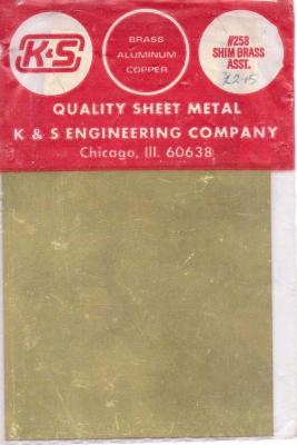
I had better add the usual disclaimer - I have no link to K&S other than as a satisfied user.
-
Mark,
I must admit I hadn't considered using a drill press to drill the main mast hole - I thought the ship would be too big to fit securely to my press/mill. I will have a look at that. The other advantage of using the press/mill is that I can set the 2 degree rearwards cant more easily than doing it by hand. Hum - got me thinking - thanks for that.
-
Peter and ZyXuz, thank you for your kind words.
Opening up the waist greatly increases the amount of interesting detail that will be visible. When I come to plant the main mast in the gun deck it will need some care in positioning it.
One concern I have is in drilling the hole in the deck to take the main mast. The drill bit will go through the thin plywood deck then in to the top edge of the plywood (very false) keel. The plywood keel is 4mm thick. Now if I use drill bits greater than 4mm diameter I think the bit (like humans) will take the path of least resistance ie down one side of the keel or the other. This will result in a seriously off centre hole. So the plan is to drill 3.5mm and to turn the lower end of the mast down to that diameter. The partners will hide the subterfuge.
Before going much further I am going to turn the masts to help in lining up the deck furniture and fittings. I have decided to replace the softwood dowel supplied in the kit with hardwood. To this end I am going to order up some walnut doweling. Does anyone have a view on which wood makes good unpainted masts?
I am still concerned about the position of the mizzen mast. Once I have a mizzen mast turned up I will post some photos to illustrate my concerns/issues.
- Landlubber Mike and ZyXuz
-
2
-
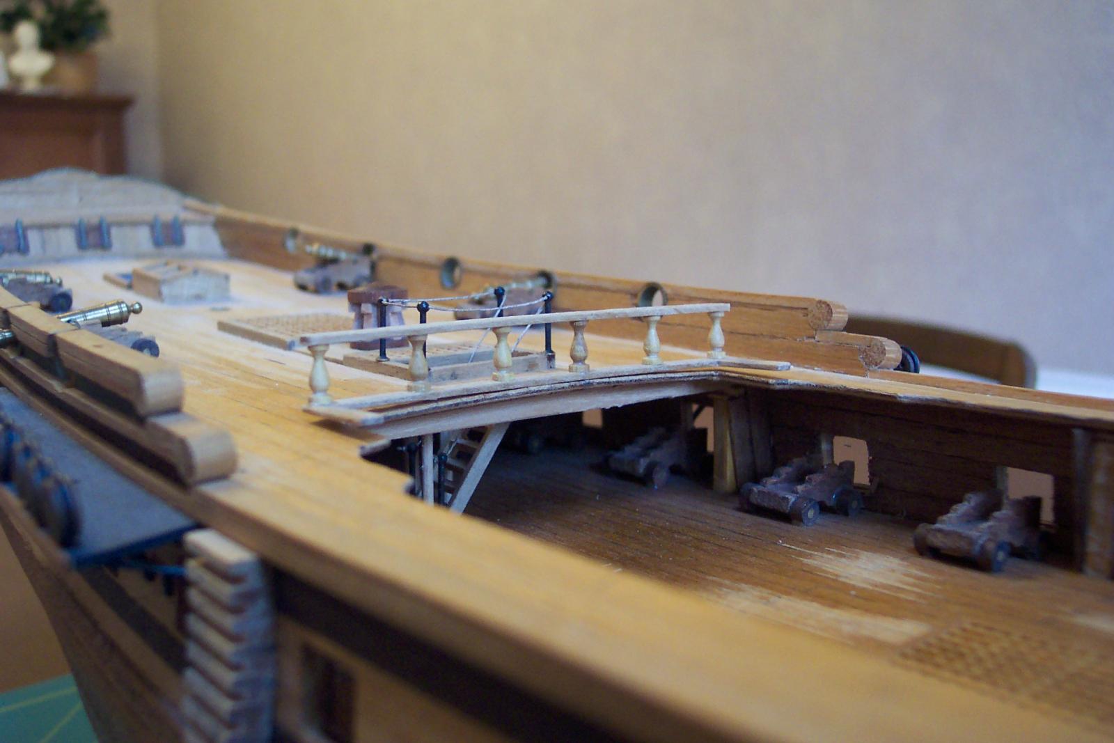
Slow progress with the internal planking I am afraid. It is very fiddly planking under the weather deck and around the cannon. It feels like I am doing ship in a bottle type activity - though this is more bottle in a ship.
I have used the mahogany strip left over from the outer deck planking which is not ideal since it tends to split very easily. I also decided to plank the bulkhead extensions that are now on view. They were shewing up as chunks of light coloured plywood amongst the cannon. These non prototypical pieces do not glare at me now they are covered in mahogany. The downside is that cladding them increases their size.
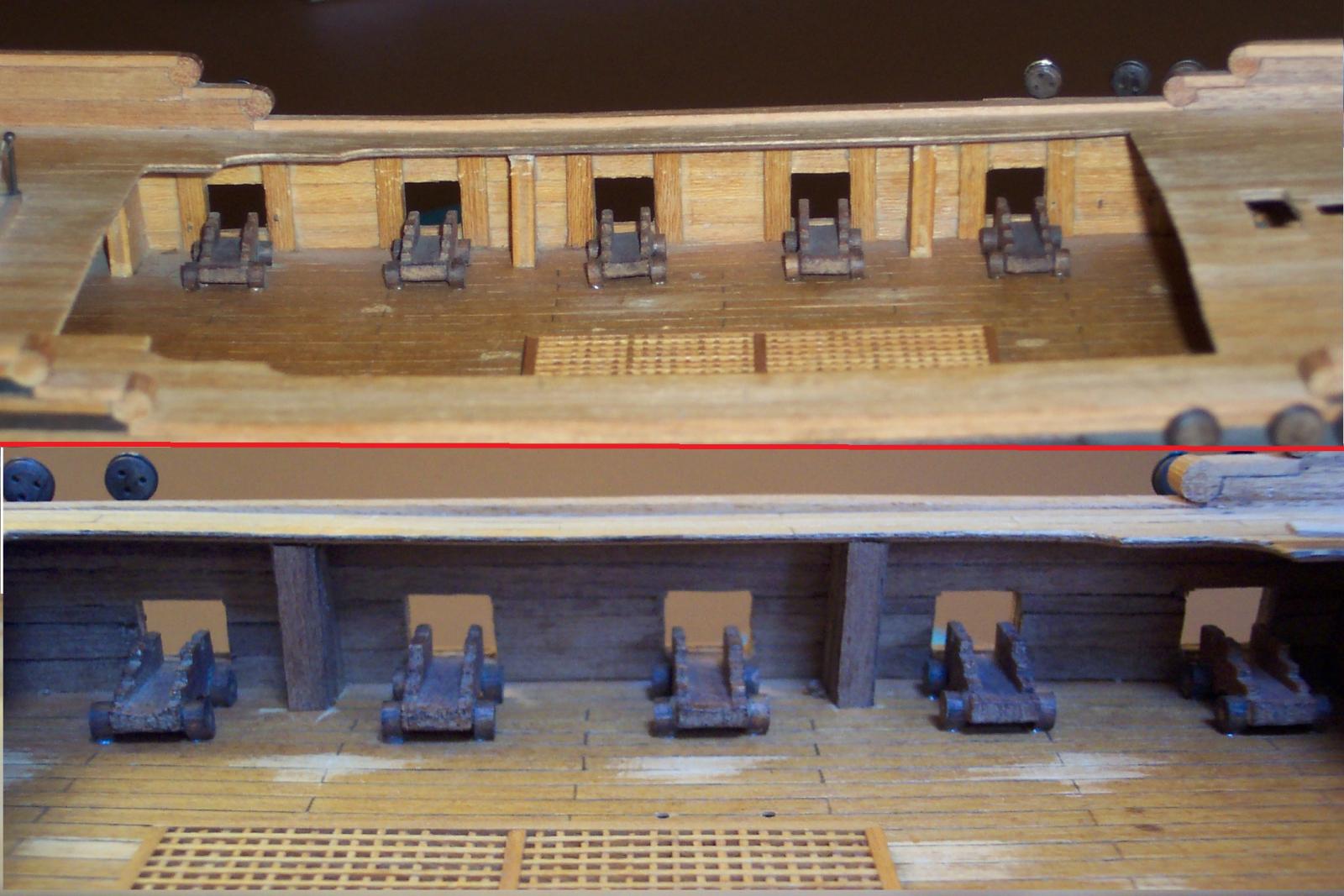
The next photo shews the before (above the red line) and after planking. The mahogany used had some very dark grain in it which unfortunately make some of the joints look as though they are gaping.
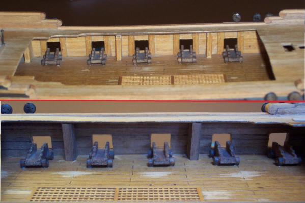
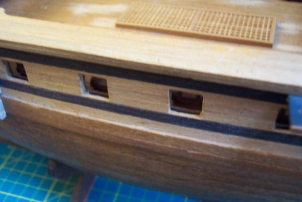
Viewed from the outside a gap can be seen between the inner and outer planking around the gun ports. So the next job will be to line the ports.
In parallel I have been producing a quarter deck rail using the pillars supplied in the kit for the now redundant rails on the old waist layout. The picture shews the partially complete rail resting in place. The rail will stand on 3mm cubes of walnut to raise it to its final height.
I haven't quite got the curvature of it right yet. The parts of the rail that point forward are alongside the steps down from the quarter deck on the real ship which won't exist on my model.
You may notice in this photo the one bulkhead had only been partially clad at that stage.

- Landlubber Mike, hamilton, IgorSky and 5 others
-
8
-
Candice,
There are some very good "how to" articles in the "Articles and Down loads" section. Click just to the right of the "MODEL SHIP World 2.0" at the top of the page. On the next page presented click on the "Articles and Downloads", then click on the "Framing and Planking". You will find all sorts of articles which will help you at this stage of your build.
In particular there is a very good article by Dirk De Bakker and Greg Brooker called "Simple Hull Planking for Beginners" ( direct link ) . It will explain all about things like rabbets (which I always thought had four legs until I read this) and other things.
There are other planking articles and hull building articles in there.
Hope this helps.
-
Freek,
The model is coming along very nicely.
I am trying to visualize the size of the model - the pencil gives me a clue. It would be great to have a rule alongside it in some of the photos to help.
Keep up the good work.
-
John,
My input - don't give it a Viking funeral. There are two ways that you can look at it. Carry on with it, make all the mistakes now so that when you do the other ships you will have much more experience to tackle them. Alternatively if you are frustrated with it put it aside for a few weeks. You may look on it more kindly then and carry on. Either way there is much to be gained from it - and it does look very nice to me.
-
Gianni,
OK. You can put your photos in your existing Unicorn log. If you are having problems drop me a PM and I will try to help.
Meanwhile back to the planking. I am not enthusiastic about planking so I am producing a quarterdeck rail at the same time. This is basically a few strips of 1mm thick walnut cut 3mm wide, some cubes of walnut 3mm square and 6 of the ornate pillars that were supplied with the kit to support the belaying pin racks. Hopefully I will have some photos of this soon.
-
Gianni,
You certainly have a lot on your plate.
I thought I saw some fresh photos of your upgrade Unicorn with full hull views. I was going to have a closer look at them but can't find them again - I don't think I was imagining things.
In particular I was looking at the area around the stern and the galleries. If I am not mistaken you have used the decorative castings on top of the galleries but not the ones underneath. Did you increase the size of the galleries to make the top castings fit?


HMS Victory by dafi - Heller - PLASTIC - To Victory and beyond ...
in - Kit build logs for subjects built from 1751 - 1800
Posted
Dafi,
I have been thinking about getting a pair of those lenses. I didn't realise that they also give new dimensions to self photography!

